EP1418078A2 - Power plant mounting apparatus - Google Patents
Power plant mounting apparatus Download PDFInfo
- Publication number
- EP1418078A2 EP1418078A2 EP03025407A EP03025407A EP1418078A2 EP 1418078 A2 EP1418078 A2 EP 1418078A2 EP 03025407 A EP03025407 A EP 03025407A EP 03025407 A EP03025407 A EP 03025407A EP 1418078 A2 EP1418078 A2 EP 1418078A2
- Authority
- EP
- European Patent Office
- Prior art keywords
- power plant
- mounting apparatus
- mount
- vehicle
- outer tube
- Prior art date
- Legal status (The legal status is an assumption and is not a legal conclusion. Google has not performed a legal analysis and makes no representation as to the accuracy of the status listed.)
- Granted
Links
Images


Classifications
-
- B—PERFORMING OPERATIONS; TRANSPORTING
- B60—VEHICLES IN GENERAL
- B60K—ARRANGEMENT OR MOUNTING OF PROPULSION UNITS OR OF TRANSMISSIONS IN VEHICLES; ARRANGEMENT OR MOUNTING OF PLURAL DIVERSE PRIME-MOVERS IN VEHICLES; AUXILIARY DRIVES FOR VEHICLES; INSTRUMENTATION OR DASHBOARDS FOR VEHICLES; ARRANGEMENTS IN CONNECTION WITH COOLING, AIR INTAKE, GAS EXHAUST OR FUEL SUPPLY OF PROPULSION UNITS IN VEHICLES
- B60K5/00—Arrangement or mounting of internal-combustion or jet-propulsion units
- B60K5/12—Arrangement of engine supports
-
- B—PERFORMING OPERATIONS; TRANSPORTING
- B62—LAND VEHICLES FOR TRAVELLING OTHERWISE THAN ON RAILS
- B62D—MOTOR VEHICLES; TRAILERS
- B62D21/00—Understructures, i.e. chassis frame on which a vehicle body may be mounted
- B62D21/11—Understructures, i.e. chassis frame on which a vehicle body may be mounted with resilient means for suspension, e.g. of wheels or engine; sub-frames for mounting engine or suspensions
Definitions
- the present invention relates to an apparatus for elastically supporting a power plant by a vehicle frame member such as a side member in a vehicle.
- the conventional power plant mounting apparatus for a vehicle is configured in a manner that a power plant 1, in which an engine and a transmission are integrally coupled to each other and laid horizontally, is supported on a vehicle body at three points, that is, at a mount member 3, at a mount member 5 and at a roll rod mount member 7.
- the power plant mounting apparatus is configured by the mount member 3 provided between the upper portion of the power plant 1 and a left side member 2 which extends in the longitudinal direction of the vehicle and has a closed section, the mount member 5 provided between the upper portion of the power plant 1 and a right side member 4 which extends in the longitudinal direction of the vehicle and has a closed section, and the roll rod mount member 7 provided so as to straddle between the lower portion of the power plant 1 and a chassis cross member 6 extending in a direction perpendicular to the longitudinal direction of the vehicle, that is, a vehicle width direction.
- the mount member 3 includes a mount bracket 10 having an almost U-shaped section. A bottom portion of the mount bracket 10 is fixed to an inner side surface of the left side member 2. Both tip ends of the mount bracket 10 protrude in the vehicle width direction.
- the mount member 3 further includes an inner tube 12 and an outer tube 13 between which an insulator 11 formed by rubber-like elastic member is provided, and a bolt 14 having both ends that are respectively engaged with the both tip ends of the mount bracket 10 in a state that the bolt penetrates through the inner tube 12 and extends in the longitudinal direction of the vehicle.
- An arm 15 of the outer tube 13 is secured to the upper portion of the power plant 1 by means of bolts.
- the mount member 5 is configured by a not-shown inner tube and an outer tube 16 between which an insulator formed by rubber-like elastic member is provided, and a not-shown bolt which is fixed to the upper portion of the power plant 1 via an arm 17 in a state that the bolt penetrates through the inner tube and extends vertically.
- the outer tube 16 is secured to the upper portion of the right side member 4 by means of a bolt.
- the roll rod mount member 7 includes a two-branched mount bracket 18 fixed to the chassis cross member 6. Both tip ends of the bracket 18 protrude in the forward direction of the vehicle.
- the roll rod mount member 7 further includes a rod 20 one end of which is coupled to the bottom portion of the power plant 1 and the other end of which is integrally formed with an outer tube 19, an insulator 21 formed by rubber-like elastic member and provided between a not-shown inner tube and the outer tube 19, and a bolt 22 having both ends that are respectively engaged with the both tip ends of the mount bracket 18 in a state that the bolt penetrates through the inner tube and extends in the vehicle width direction.
- the power plant 1 is pivotally supported at three points on the vehicle body by means of the mount member 3, the mount member 5 and the roll rod mount member 7.
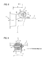
- the shaft center of the bolt 14, which acts as the point of action of a load at the time of transmitting a vibratory force of the power plant 1 and an inertial force of the power plant 1 caused by accelerating or decelerating the running of the vehicle or by the steering operation and transmitted from the power plant 1 side to the left side member 2 side, is made largely offset by a distance d in the vehicle width direction from the sectional center point Q of the left side member 2.
- the supporting rigidity of the mount member 3 for supporting the power plant 1 is degraded, and the vibration damping characteristics of the mount member 3 is not enough. Since a relatively large space is required between the power plant 1 and the left side member 2, a position for disposing the mount member 3 within the engine compartment that is already narrow may be limited.
- a roll input force as a reaction force of the wheels acts on the power plant 1 as shown by an arrow A in Fig. 9.
- the mount member 3 provided at the upper portion of the power plant 1 has a low rigidity along the axial direction (the longitudinal direction of the vehicle). Since a load is applied to the mount member 3 along the axial direction, it is difficult for the mount member 3 to surely support the roll input force.
- the mount member 3 is required to be provided with stoppers 25, 25 formed by rubber-like elastic member in order to prevent the outer tube 13 from being made metal-contact with the tip portion of the mount bracket 10, when the outer tube 13 of the mount member 3 inclines in the longitudinal direction of the vehicle due to the elastic deformation of the insulator 11 caused by the roll input force, etc.
- a roll input force directed in the direction opposite to the arrow A in Fig. 9 acts on the power plant 1 so that a disadvantage similar to that of the aforesaid case arises.
- the fixing position of the mount member 3 with respect to the left side member 2 is required to be set at the most suitable position for each kind of the power plant 1.
- the present invention has been made to solve the above problems, and therefore one object of the invention is to provide a power plant mounting structure in which a vehicle frame member elastically supports a power plant and inwhich an offset distance between a vehicle frame member and a point of action of a load transmitted from the power plant side to the vehicle frame member side is reduced.
- Another object of the invention is to provide a power plant mounting structure which occupies a small space and which surely supports a roll input force acting on a power plant.
- Still another object of the invention is to provide a power plant mounting structure in which an attachment position of a mount member with respect to a side member of a vehicle can be easily changed.
- a power plant mounting apparatus including: a vehicle frame member constituting a vehicle frame; a mount member having an elastic member and connecting a power plant and the vehicle frame member; wherein at least a part of the mount member is positioned inside the vehicle frame member; and a load applied to the vehicle frame member from the power plant is transmitted through the elastic member.
- the vehicle frame member may have a side member extending in a longitudinal direction of a vehicle
- the mount member may include a shaft portion and an outer tube between which the elastic member is disposed in an annular manner, and a shaft center of each of the shaft portion and the outer tube may extend in a vehicle width direction.
- the vehicle frame member may have a side member extending in a longitudinal direction of a vehicle
- the mount member may include a shaft portion coupled to the power plant and an outer tube between which the elastic member is disposed in an annular manner, a flange portion fixed to the outer tube may have a long hole, and the flange portion may be fixed to the side member by a bolt penetrating through the long hole.
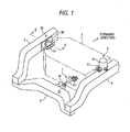
- Figs. 1 and 2 show a power plant mounting apparatus for a vehicle according to a first embodiment of the invention.
- the power plant mounting apparatus is configured in a manner that a power plant 1, in which an engine and a transmission are integrally coupled to each other and laid horizontally, is supported on a vehicle body at three points, that is, at a mount member 30, at a mount member 5 and at a roll rod mount member 7.
- the power plant mounting apparatus includes the mount member 30 provided between the upper portion of the power plant 1 and a left side member 2 which extends in the longitudinal direction of the vehicle and has a closed section, the mount member 5 provided between the upper portion of the power plant 1 and a right side member 4 which extends in the longitudinal direction of the vehicle and has a closed section, and the roll rod mount member 7 provided so as to straddle between the lower portion of the power plant 1 and a chassis cross member 6 extending at the rear side portion of the vehicle in a direction perpendicular to the longitudinal direction of the vehicle, that is, a vehicle width direction.
- Each of the left and right side members 2 and 4 has a cross section of a closed section.
- the closed section maybe a rectangular shape, circular shape, elliptic shape or other shape made of a closed curve.
- the closed section is made of a closed curve having no cot out portion.
- the mount member 30 includes a supporting member 33 having a flange 31 and a shaft portion 32 extending in the vehicle width direction, an outer tube 34 for surrounding the outer periphery of the shaft portion 32, an insulator 35 circularly disposed between the shaft portion 32 and the outer tube 34 and formed by rubber-like elastic member, and a bracket 36 of an almost flat plate-shape at which the outer tube 34 is fixed by means such as press fitting or welding.
- the flange 31 of the supporting member 33 is secured at the upper portion of the power plant 1 by means of bolts.
- the bracket 36 is secured at an inner side surface 37 of a left side member 2 by means of bolts.
- Each of the shaft portion 32 of the supporting member 33 and the outer tube 34 has a shaft center extending in almost the vehicle width direction and the center point P of the shaft portion 32 within the outer tube 34 is positioned within the left side member 2.
- 2' depicts a reinforcement attached to a surface inside the left side member 2.
- a load to be transmitted to the left side member 2 side from the power plant 1 side is buffered by the insulator 35 when transmitted from the supporting member 33 through the insulator 35, the outer tube 34 and the bracket 36 sequentially. Since the point of action of the load acting on the shaft portion 32 of the supporting member 33, that is, the center point P is positioned within the left side member 2, an offset distance D in the vehicle width direction between a sectional center point R of the left side member 2 and the center point P can be made shorter as compared with the case of the conventional apparatus.
- a bending input force and a torsional input force acting on the left side member 2 through the mount member 30 due to the load from the power plant 1 can be more reduced as compared with the conventional apparatus.
- the supporting rigidity of the mount member 30 for supporting the powerplant 1 canbe enhanced, so that the transmissionof vibration to the vehicle body and the generation of noise can be effectively suppressed.
- the mount member 30 can be easily disposed at the position within the engine compartment which is effective as to suppress the vibration and noise, etc.
- the shaft portion 32 of the supporting member 33 is positioned within the left side member 2, the space within the left side member 2 which has not been used conventionally is used for disposing the mount member 30. Thus, the space within the engine compartment can be used more effectively.
- the sectional center point R of the left side member 2 and the center point P of the load acting on the shaft portion 32 of the supporting member 33 may be made coincide to each other so that the offset distance D becomes minimum.
- known elastic member in which liquid is sealed may be used instead of the rubber-like elastic member as the insulator in the mount member.
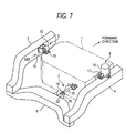
- a mount member 130 includes a supporting member 33 having a flange 31 and a shaft portion 32 extending in the vehicle width direction, an outer tube 34 for surrounding the outer periphery of the shaft portion 32, an insulator 35 circularly disposed between the shaft portion 32 and the outer tube 34 and formed by rubber-like elastic member, and a bracket 36 of an almost flat plate-shape at which the outer tube 34 is fixed by means such as press fitting or welding.
- the flange 31 of the supporting member 33 is secured at the upper portion of the power plant 1 by means of bolts.
- the bracket 36 is secured at the inner side surface 37 of the left side member 2 by means of stud bolts 38 and nuts 39.
- Each of the shaft portion 32 and the outer tube 34 of the supporting member 33 has a shaft center extending in almost the vehicle width direction. Most portion of each of the shaft portion 32, the outer tube 34 and the insulator 35 is positioned within the left side member 2.
- 2' depicts a reinforcement attached to a surface inside the left side member 2.
- the mount member 130 of this power plant mounting apparatus most portion of each of the shaft portion 32 of the supporting member, the outer tube 34 and the insulator 35 is disposed within the left side member 2.
- the mount member 3 is provided at the inner side of the left side member 2
- the distance in the vehicle width direction between the power plant 1 and the left side member 2, that is, a required space therebetween can be made small.
- the mount member 130 can be easily disposed at the position within the engine compartment which is effective as to suppress the vibration and noise, etc.
- the space within the left side member 2 which has not been used conventionally is used for disposing the mount member 130, the space within the engine compartment can be used more effectively.
- the shaft center of each of the shaft portion 32 of the supporting member 33 and the outer tube 34 extends in the vehicle width direction, and the insulator 35 is provided in an annular shape between the shaft portion 32 and the outer tube 34.
- the lower portion of the power plant 1 is coupled to the chassis cross member 6 with a sufficient intensity in the longitudinal direction of the vehicle by means of the roll rod mount 7.
- the insulator 35 disposed in the annular shape between the shaft portion 32 and the outer tube 34 can perform a stopper function for suppressing the interference between the shaft portion 32 and the outer tube 34.
- known elastic member in which liquid is sealed may be used instead of the rubber-like elastic member as the insulator in the mount member.
- a mount member 230 includes a supporting member 33 having an arm 31 and a shaft portion 32 extending in the vehicle width direction, an outer tube 34 for surrounding the outer periphery of the shaft portion 32, an insulator 35 circularly disposed between the shaft portion 32 and the outer tube 34 and formed by rubber-like elastic member, and a flange portion 36 of an almost flat plate-shape at which the outer tube 34 is integrally fixed by means such as press fitting or welding.
- the arm 31 of the supporting member 33 is secured at the upper portion of the power plant 1 by means of bolts.
- each of the shaft portion 32 and the outer tube 34 of the supporting member 33 has a shaft center extending in almost the vehicle width direction. Most portion of each of the shaft portion 32, the outer tube 34 and the insulator 35 is positioned within the left side member 2. Further, each of the long holes 40 extends straightly in the longitudinal direction of the vehicle.
- 2' depicts a reinforcement attached to an surface inside the left side member 2.
- the mount member 230 of this power plant mounting apparatus most portion of each of the shaft portion 32 of the supporting member, the outer tube 34 and the insulator 35 is disposed within the left side member 2.
- the mount member 3 is provided at the inner side of the left side member 2, the distance in the vehicle width direction between the power plant 1 and the left side member 2, that is, a required space therebetween can be made small.
- the outer tube 34 of the mount member 230 is fixed to the inner side surface 37 of the left side member 2 by means of the stud bolts 38 and the nuts 39 passing through the long holes 40 of the flange portion 36.
- the attachment position of the mount member 230 with respect to the left side member 2 can be easily changed by suitably shifting the stud bolts 38 along the long holes 40 in the longitudinal direction of the vehicle.
- the attachment position of the mount member 230 to the left side member 2 can be easily changed in the longitudinal direction of the vehicle.
- the degree of such a necessity for preparing many kinds of the left side members 2 respectively having different fixing positions of the stud bolts 38 in accordance with the change of the specification of the power plant 1 can be reduced. Therefore, it becomes possible to easily reduce the cost of the left side member 2.
- the space within the left side member 2 which has not been used conventionally is used for disposing the mount member 230, the space within the engine compartment can be used more effectively.
- each of the long holes 40 of the flange portion 36 extends linearly in the longitudinal direction of the vehicle
- the action and effects similar to those of the aforesaid embodiment can be attained when each of the long holes is arranged to extend in a suitably slanted manner linearly or in a gentle arc-shape in the longitudinal direction of the vehicle.
- known elastic member in which liquid is sealed may be used instead of the rubber-like elastic member as the insulator in the mount member.
- the center of a load acting on the vehicle frame member from the power plant is positioned within the vehicle frame member.
- the offset distance between the center of the load and the center of the vehicle frame member can be made shorter easily as compared with the conventional apparatus.
- the supporting rigidity of the mount member for supporting the power plant can be enhanced, so that the transmission of vibration to the vehicle body and the generation of noise can be effectively suppressed.
- the space necessary between the power plant and the vehicle frame member can be made relatively small, so that the degree of freedom as to the setting position of the mount member can be made easily large.
- the mount member can be likely disposed at a suitable position.
- the shaft member and the outer tube of the mount member is disposed within the side member.
- the space required for disposing the mount member between the power plant and the side member can be made relatively small.
- the degree of freedom as to the setting position of the mount member can be made easily large. Therefore, the mount member can be likely disposed at a suitable position.
- the shaft center of each of the shaft portion and the outer tube of the mount member is configured to extend in almost the vehicle width direction, and the load in the longitudinal direction of the vehicle applied to the mount member due to the roll input force acting on the power plant can be surely supported by the mount member. Accordingly, the power plant can be always supported stably by the power plant mounting apparatus.
- the shaft member and the outer tube of the mount member is disposed within the side member, and so the space required for disposing the mount member between the power plant and the side member can be made relatively small.
- the degree of freedom as to the setting position of the mount member can be made easily large.
- the mount member can be likely disposed at a suitable position.
- the flange portion is fixed to the side member by means of the bolts that penetrate through the long holes of the flange portion that are integrally formed with the outer tube.
- the attachment position of the mount member with respect to the side member can be easily and suitably changed by relatively shifting the bolts within the long holes. Accordingly, the vibration, etc., of the power plant can be effectively reduced by the mount member.
- the degree of such a necessity for preparing many kinds of the side members respectively having different fixing positions of the mount members in accordance with the change of the specification of the power plant can be reduced.
Landscapes
- Engineering & Computer Science (AREA)
- Chemical & Material Sciences (AREA)
- Combustion & Propulsion (AREA)
- Transportation (AREA)
- Mechanical Engineering (AREA)
- Arrangement Or Mounting Of Propulsion Units For Vehicles (AREA)
- Body Structure For Vehicles (AREA)
- Fittings On The Vehicle Exterior For Carrying Loads, And Devices For Holding Or Mounting Articles (AREA)
- Handcart (AREA)
Abstract
Description
Claims (22)
- A power plant mounting apparatus comprising:wherein at least a part of the mount member is positioned inside the vehicle frame member; anda vehicle frame member constituting a vehicle frame;a mount member having an elastic member and connecting a power plant and the vehicle frame member;
a load applied to the vehicle frame member from the power plant is transmitted through the elastic member. - The power plant mounting apparatus according to claim 1, wherein a point of action of the load exerted on the mount member is positioned within the vehicle frame member.
- The power plant mounting apparatus according to claim 1 or 2, wherein the vehicle frame member has a cross section of a closed section.
- The power plant mounting apparatus according to claim 1, 2, or 3, wherein the vehicle frame member comprises a side member extending in a longitudinal direction of a vehicle.
- The power plant mounting apparatus according to any of claims 1 to 4, wherein the mount member includes a shaft portion and an outer tube, and the elastic member is disposed in an annular manner between the shaft portion and the outer tube.
- The power plant mounting apparatus according to claim 5, wherein one end of the shaft portion is fixed to the power plant and the other end of the shaft portion is inserted in the outer tube fixed to the side member; and
when the load is exerted on the shaft member, a center point of the shaft portion within the outer tube serves as the point of action of the load. - The power plant mounting apparatus according to any of claims 1 to 6, further comprising a roll rod mount member that enables a chassis cross member disposed at a rear side portion of the vehicle to support the power plant;
wherein both end portions in a vehicle width direction of the power plant are supported by left and right side members, and at least one end portion of the power plant is supported by the side member via the mount member. - The power plant mounting apparatus according to any of claims 1 to 7, wherein the vehicle frame member comprises a sidemember extending in a longitudinal direction of a vehicle;
the mount member includes a shaft portion and an outer tube, and the elastic member is disposed in an annular manner between the shaft portion and the outer tube; and
a shaft center of each of the shaft portion and the outer tube substantially extends in a vehicle width direction. - The power plant mounting apparatus according to claim 8, wherein the side member has a cross section of a closed section.
- The power plant mounting apparatus according to claim 8 or 9, wherein the mount member is coupled to an upper portion of the power plant.
- The power plant mounting apparatus according to claim 8, 9, or 10, wherein the shaft portion is fixed to the power plant and the outer tube is fixed to the side member.
- The power plant mounting apparatus according to claim 11, further comprising:a second mount member that enables a side member opposite to the side member to which the mount member is connecting the power plant to elastically support the power plant; anda roll rod mount member that enables a chassis cross member disposed at a rear side portion of the vehicle to support the power plant.
- The power plant mounting apparatus according to claim 12, wherein each of the mount members is coupled to an upper portion of the power plant, and the roll rod mount member is coupled to a lower portion of the power plant.
- The power plant mounting apparatus according to claim 1, wherein the vehicle frame member comprises a side member extending in a longitudinal direction of a vehicle;
the mount member includes a shaft portion coupled to the power plant and an outer tube, and the elastic member is disposed in an annular manner between the shaft portion and the outer tube;
a flange portion fixed to the outer tube has a long hole; and
the flange portion is fixed to the side member by a bolt penetrating through the long hole. - The power plant mounting apparatus according to claim 14, wherein the long hole substantially extends in the longitudinal direction of the vehicle.
- The power plant mounting apparatus according to claim 14, wherein the long hole extends in a slanted manner with respect to a vertical direction or the longitudinal direction of the vehicle.
- The power plant mounting apparatus according to 15 or 16, wherein the bolt is a stud bolt fixed to the side member.
- The power plant mounting apparatus according to claim 17, wherein the side member has a cross section of a closed section.
- The power plant mounting apparatus according to claim 18, wherein the shaft portion is coupled to an upper portion of the power plant.
- The power plant mounting apparatus according to claim 19, further comprising:a second mount member that enables a side member opposite to the side member to which the mount member is connecting the power plant to elastically support the power plant; anda roll rod mount member that enables a chassis cross member disposed at a rear side portion of the vehicle to support the power plant.
- The power plant mounting apparatus according to claim 20, wherein the second mount member is coupled to the upper portion of the power plant, and the roll rod mount portion is coupled to a lower portion of the power plant.
- The power plant mounting apparatus according to any of claims 14 to 21, wherein the flange portion is fixed to a vertical wall of the side member.
Applications Claiming Priority (6)
| Application Number | Priority Date | Filing Date | Title |
|---|---|---|---|
| JP2002323220 | 2002-11-07 | ||
| JP2002323218 | 2002-11-07 | ||
| JP2002323221A JP3896948B2 (en) | 2002-11-07 | 2002-11-07 | Power plant mounting device |
| JP2002323221 | 2002-11-07 | ||
| JP2002323218A JP2004155323A (en) | 2002-11-07 | 2002-11-07 | Power plant mounting equipment |
| JP2002323220A JP2004155324A (en) | 2002-11-07 | 2002-11-07 | Power plant mounting equipment |
Publications (3)
| Publication Number | Publication Date |
|---|---|
| EP1418078A2 true EP1418078A2 (en) | 2004-05-12 |
| EP1418078A3 EP1418078A3 (en) | 2004-10-06 |
| EP1418078B1 EP1418078B1 (en) | 2007-02-14 |
Family
ID=32110663
Family Applications (1)
| Application Number | Title | Priority Date | Filing Date |
|---|---|---|---|
| EP03025407A Expired - Lifetime EP1418078B1 (en) | 2002-11-07 | 2003-11-05 | Power plant mounting apparatus |
Country Status (7)
| Country | Link |
|---|---|
| US (1) | US7232005B2 (en) |
| EP (1) | EP1418078B1 (en) |
| KR (1) | KR100570591B1 (en) |
| CN (1) | CN1295094C (en) |
| DE (1) | DE60311728T2 (en) |
| MY (1) | MY138489A (en) |
| TW (1) | TWI259815B (en) |
Cited By (4)
| Publication number | Priority date | Publication date | Assignee | Title |
|---|---|---|---|---|
| WO2010084258A1 (en) * | 2009-01-26 | 2010-07-29 | Peugeot Citroën Automobiles SA | Device for the lower suspension of an automobile engine |
| FR2962400A1 (en) * | 2010-07-06 | 2012-01-13 | Peugeot Citroen Automobiles Sa | Horn device for connecting front part of cradle of front structure of motor vehicle with longerons of case of motor vehicle by articulation axle, has fixing unit cooperating with adjusting units to integrate tubular element in ring |
| CN102848893A (en) * | 2011-06-28 | 2013-01-02 | 财团法人金属工业研究发展中心 | Power module fixing support of electric vehicle |
| US11345403B2 (en) * | 2019-09-30 | 2022-05-31 | Cnh Industrial America Llc | Engine mounting system for a work vehicle |
Families Citing this family (20)
| Publication number | Priority date | Publication date | Assignee | Title |
|---|---|---|---|---|
| JP4721404B2 (en) * | 2005-01-28 | 2011-07-13 | 本田技研工業株式会社 | Mount structure for vehicle power unit |
| DE102005055396A1 (en) * | 2005-11-17 | 2007-05-24 | Automotive Group Ise Innomotive Systems Europe Gmbh | Torque crossmember |
| US20070131469A1 (en) * | 2005-12-08 | 2007-06-14 | Hyo-Seok Kim | Power train mounting apparatus of vehicle |
| JP5141026B2 (en) * | 2006-02-27 | 2013-02-13 | トヨタ自動車株式会社 | In-vehicle structure of power storage pack |
| FR2904954A1 (en) * | 2006-08-16 | 2008-02-22 | Renault Sas | STRUCTURAL ELEMENT OF A MOTOR VEHICLE |
| US8118288B2 (en) * | 2007-10-01 | 2012-02-21 | Briggs & Stratton Corporation | Isolation mount system |
| JP4930576B2 (en) * | 2009-02-27 | 2012-05-16 | 日産自動車株式会社 | Motor support structure |
| US8215444B2 (en) * | 2009-07-09 | 2012-07-10 | Ford Global Technologies | Roll restrictor system for an automotive powertrain |
| JP5861302B2 (en) * | 2011-07-29 | 2016-02-16 | 日産自動車株式会社 | Vibration isolator for vehicle |
| KR101738018B1 (en) * | 2011-08-19 | 2017-05-19 | 현대자동차주식회사 | Structure of roll-rod for subframe |
| US20130105241A1 (en) * | 2011-10-26 | 2013-05-02 | Coda Automotive, Inc. | Electric vehicle powertrain suspension system |
| JP5811769B2 (en) * | 2011-10-27 | 2015-11-11 | トヨタ自動車株式会社 | Vehicle front structure |
| EP2749478B1 (en) * | 2012-01-16 | 2016-03-16 | Toyota Jidosha Kabushiki Kaisha | Structure for front section of vehicle body |
| US9340229B2 (en) * | 2012-05-21 | 2016-05-17 | Magna International Inc. | Cradle assembly for a vehicle |
| US10830302B2 (en) * | 2017-03-27 | 2020-11-10 | Hutchinson Aerospace & Industry, Inc. | Continuous framework for shock, vibration and thermal isolation and motion accommodation |
| DE102018204277A1 (en) * | 2018-03-20 | 2019-09-26 | Bayerische Motoren Werke Aktiengesellschaft | Bearing arrangement for an engine of a motor vehicle, method for its production and press-in device for pressing the bearing in the motor carrier |
| DE102019111905A1 (en) * | 2019-05-08 | 2020-11-12 | Bayerische Motoren Werke Aktiengesellschaft | Carrying device for a motor vehicle and a mounting arrangement for a drive motor on a carrier element of a motor vehicle |
| WO2022157833A1 (en) | 2021-01-19 | 2022-07-28 | 日産自動車株式会社 | Pendulum-type mount system |
| FR3124767A1 (en) * | 2021-07-02 | 2023-01-06 | Psa Automobiles Sa | SUSPENSION DEVICE FOR A MOTOR VEHICLE POWERTRAIN |
| DE102022115121A1 (en) | 2022-06-15 | 2023-12-21 | Bayerische Motoren Werke Aktiengesellschaft | Storage arrangement of a first component on a second component of a vehicle, in particular a motor vehicle, and vehicle |
Family Cites Families (22)
| Publication number | Priority date | Publication date | Assignee | Title |
|---|---|---|---|---|
| NL121798C (en) * | 1900-01-01 | |||
| BE366754A (en) * | ||||
| US1578673A (en) * | 1921-06-13 | 1926-03-30 | Int Motor Co | Cushioned support for the units of motor vehicles |
| US1828278A (en) * | 1926-05-12 | 1931-10-20 | Chrysler Corp | Dampener |
| USRE18457E (en) * | 1927-01-10 | 1932-05-10 | Vibeation dampening mounting | |
| GB494362A (en) * | 1937-06-19 | 1938-10-25 | Grave Short & Company Ltd De | Improvements relating to dispensing scales |
| DE766585C (en) * | 1941-01-03 | 1951-11-29 | Carl F W Borgward | Elastic self-aligning bearings for motor vehicle engines |
| US4031978A (en) * | 1975-05-28 | 1977-06-28 | Tayco Developments, Inc. | Energy absorber unit and energy management system |
| JPS56118524A (en) * | 1980-02-26 | 1981-09-17 | Yamaha Motor Co Ltd | Overhead camshaft v type engine for vehicle |
| JPS5940946A (en) * | 1982-09-01 | 1984-03-06 | Nissan Motor Co Ltd | Support structure of power unit in vehicle |
| US4617212A (en) * | 1985-03-01 | 1986-10-14 | Gencorp Inc. | Bushing |
| US5178230A (en) * | 1990-12-19 | 1993-01-12 | Goor Associates, Inc. | Engine mounting system |
| US5862877A (en) * | 1994-12-20 | 1999-01-26 | Cosma International Inc. | Cradle assembly |
| CN2225986Y (en) * | 1995-05-16 | 1996-05-01 | 刘建辉 | Rotary support for automobile engine |
| JP3351233B2 (en) | 1995-12-27 | 2002-11-25 | トヨタ自動車株式会社 | Powertrain support device |
| JP2002503557A (en) * | 1998-02-17 | 2002-02-05 | コスマ インターナショナル インコーポレイテッド | Self-extruded bush assembly and method of forming the same |
| JP2000120770A (en) | 1998-10-08 | 2000-04-25 | Fuji Heavy Ind Ltd | Automotive anti-vibration device |
| US6105548A (en) * | 1998-11-03 | 2000-08-22 | Briggs & Stratton Corporation | Mounting apparatus for an engine and transmission |
| CN2434170Y (en) * | 2000-09-04 | 2001-06-13 | 常柴集团江南运输机械有限公司 | Engine position regulator for three-wheel farm carrier vehicle |
| JP2002302087A (en) * | 2001-04-09 | 2002-10-15 | Yamaha Motor Co Ltd | Engine support structure for small vehicles |
| JP4026815B2 (en) * | 2002-09-06 | 2007-12-26 | 本田技研工業株式会社 | Subframe mounting structure |
| JP4184735B2 (en) * | 2002-09-06 | 2008-11-19 | 本田技研工業株式会社 | Vehicle power source mounting structure |
-
2003
- 2003-10-24 TW TW092129534A patent/TWI259815B/en not_active IP Right Cessation
- 2003-11-03 MY MYPI20034194A patent/MY138489A/en unknown
- 2003-11-05 US US10/700,665 patent/US7232005B2/en not_active Expired - Fee Related
- 2003-11-05 EP EP03025407A patent/EP1418078B1/en not_active Expired - Lifetime
- 2003-11-05 DE DE60311728T patent/DE60311728T2/en not_active Expired - Lifetime
- 2003-11-06 KR KR1020030078213A patent/KR100570591B1/en not_active Expired - Fee Related
- 2003-11-07 CN CNB2003101034810A patent/CN1295094C/en not_active Expired - Fee Related
Cited By (6)
| Publication number | Priority date | Publication date | Assignee | Title |
|---|---|---|---|---|
| WO2010084258A1 (en) * | 2009-01-26 | 2010-07-29 | Peugeot Citroën Automobiles SA | Device for the lower suspension of an automobile engine |
| FR2941409A1 (en) * | 2009-01-26 | 2010-07-30 | Peugeot Citroen Automobiles Sa | DEVICE FOR LOWER SUSPENSION OF A MOTOR VEHICLE. |
| FR2962400A1 (en) * | 2010-07-06 | 2012-01-13 | Peugeot Citroen Automobiles Sa | Horn device for connecting front part of cradle of front structure of motor vehicle with longerons of case of motor vehicle by articulation axle, has fixing unit cooperating with adjusting units to integrate tubular element in ring |
| CN102848893A (en) * | 2011-06-28 | 2013-01-02 | 财团法人金属工业研究发展中心 | Power module fixing support of electric vehicle |
| CN102848893B (en) * | 2011-06-28 | 2015-11-25 | 财团法人金属工业研究发展中心 | Power module fixing support of electric vehicle |
| US11345403B2 (en) * | 2019-09-30 | 2022-05-31 | Cnh Industrial America Llc | Engine mounting system for a work vehicle |
Also Published As
| Publication number | Publication date |
|---|---|
| TW200413194A (en) | 2004-08-01 |
| CN1498797A (en) | 2004-05-26 |
| EP1418078A3 (en) | 2004-10-06 |
| DE60311728T2 (en) | 2007-06-28 |
| US7232005B2 (en) | 2007-06-19 |
| DE60311728D1 (en) | 2007-03-29 |
| CN1295094C (en) | 2007-01-17 |
| EP1418078B1 (en) | 2007-02-14 |
| MY138489A (en) | 2009-06-30 |
| TWI259815B (en) | 2006-08-11 |
| KR20040041022A (en) | 2004-05-13 |
| KR100570591B1 (en) | 2006-04-13 |
| US20040124034A1 (en) | 2004-07-01 |
Similar Documents
| Publication | Publication Date | Title |
|---|---|---|
| EP1418078B1 (en) | Power plant mounting apparatus | |
| JPWO2015060162A1 (en) | Vehicle equipped with engine mount | |
| KR100622384B1 (en) | Bracket mounting structure of muffler hanger rod | |
| JP2020050213A (en) | Front sub-frame structure | |
| JP4841974B2 (en) | Power unit support structure | |
| JP2004155324A (en) | Power plant mounting equipment | |
| JP4049783B2 (en) | Vehicle engine mounting device | |
| CN211032154U (en) | Support structure of power unit for vehicle | |
| JP2004155323A (en) | Power plant mounting equipment | |
| KR100475889B1 (en) | Reinforcing structure of engine mounying bracket for automobile | |
| JP3896948B2 (en) | Power plant mounting device | |
| JP3228047B2 (en) | Vehicle engine mounting device | |
| KR100314523B1 (en) | Stiffness reinforcement structure of engine mount | |
| JPH08132890A (en) | Vehicle engine mounting device | |
| KR0126057Y1 (en) | Transmission mounting for a car | |
| JP5137523B2 (en) | Vibration isolator | |
| KR100802773B1 (en) | Engine mounting device of the vehicle | |
| CN108215756B (en) | Mounting device for a drive train | |
| JP6515948B2 (en) | Powertrain mounting device | |
| JPH11129768A (en) | Mount structure of power unit | |
| JPH078035U (en) | Power unit support structure for automobiles | |
| JPH08132889A (en) | Vehicle engine mounting device | |
| JPH0655839U (en) | Support structure for automobile power unit | |
| JP2007290414A (en) | Engine support structure | |
| JP4633218B2 (en) | Support structure for steering column assembly |
Legal Events
| Date | Code | Title | Description |
|---|---|---|---|
| PUAI | Public reference made under article 153(3) epc to a published international application that has entered the european phase |
Free format text: ORIGINAL CODE: 0009012 |
|
| AK | Designated contracting states |
Kind code of ref document: A2 Designated state(s): AT BE BG CH CY CZ DE DK EE ES FI FR GB GR HU IE IT LI LU MC NL PT RO SE SI SK TR |
|
| AX | Request for extension of the european patent |
Extension state: AL LT LV MK |
|
| PUAL | Search report despatched |
Free format text: ORIGINAL CODE: 0009013 |
|
| AK | Designated contracting states |
Kind code of ref document: A3 Designated state(s): AT BE BG CH CY CZ DE DK EE ES FI FR GB GR HU IE IT LI LU MC NL PT RO SE SI SK TR |
|
| AX | Request for extension of the european patent |
Extension state: AL LT LV MK |
|
| 17P | Request for examination filed |
Effective date: 20050128 |
|
| AKX | Designation fees paid |
Designated state(s): DE FR |
|
| 17Q | First examination report despatched |
Effective date: 20050705 |
|
| GRAP | Despatch of communication of intention to grant a patent |
Free format text: ORIGINAL CODE: EPIDOSNIGR1 |
|
| GRAS | Grant fee paid |
Free format text: ORIGINAL CODE: EPIDOSNIGR3 |
|
| RIN1 | Information on inventor provided before grant (corrected) |
Inventor name: MATSUDA, EIKIC/O Inventor name: KOMATSU, JUNJIC/O |
|
| GRAA | (expected) grant |
Free format text: ORIGINAL CODE: 0009210 |
|
| AK | Designated contracting states |
Kind code of ref document: B1 Designated state(s): DE FR |
|
| REF | Corresponds to: |
Ref document number: 60311728 Country of ref document: DE Date of ref document: 20070329 Kind code of ref document: P |
|
| RAP2 | Party data changed (patent owner data changed or rights of a patent transferred) |
Owner name: MITSUBISHI JIDOSHA KOGYO KABUSHIKI KAISHA |
|
| ET | Fr: translation filed | ||
| PLBE | No opposition filed within time limit |
Free format text: ORIGINAL CODE: 0009261 |
|
| STAA | Information on the status of an ep patent application or granted ep patent |
Free format text: STATUS: NO OPPOSITION FILED WITHIN TIME LIMIT |
|
| 26N | No opposition filed |
Effective date: 20071115 |
|
| REG | Reference to a national code |
Ref country code: FR Ref legal event code: PLFP Year of fee payment: 13 |
|
| PGFP | Annual fee paid to national office [announced via postgrant information from national office to epo] |
Ref country code: DE Payment date: 20151028 Year of fee payment: 13 |
|
| PGFP | Annual fee paid to national office [announced via postgrant information from national office to epo] |
Ref country code: FR Payment date: 20151008 Year of fee payment: 13 |
|
| REG | Reference to a national code |
Ref country code: DE Ref legal event code: R119 Ref document number: 60311728 Country of ref document: DE |
|
| REG | Reference to a national code |
Ref country code: FR Ref legal event code: ST Effective date: 20170731 |
|
| PG25 | Lapsed in a contracting state [announced via postgrant information from national office to epo] |
Ref country code: FR Free format text: LAPSE BECAUSE OF NON-PAYMENT OF DUE FEES Effective date: 20161130 |
|
| PG25 | Lapsed in a contracting state [announced via postgrant information from national office to epo] |
Ref country code: DE Free format text: LAPSE BECAUSE OF NON-PAYMENT OF DUE FEES Effective date: 20170601 |