EP1418075A2 - Side door structure of vehicle - Google Patents
Side door structure of vehicle Download PDFInfo
- Publication number
- EP1418075A2 EP1418075A2 EP03025360A EP03025360A EP1418075A2 EP 1418075 A2 EP1418075 A2 EP 1418075A2 EP 03025360 A EP03025360 A EP 03025360A EP 03025360 A EP03025360 A EP 03025360A EP 1418075 A2 EP1418075 A2 EP 1418075A2
- Authority
- EP
- European Patent Office
- Prior art keywords
- door
- checker
- holder
- clamping member
- front door
- Prior art date
- Legal status (The legal status is an assumption and is not a legal conclusion. Google has not performed a legal analysis and makes no representation as to the accuracy of the status listed.)
- Granted
Links
- 238000010586 diagram Methods 0.000 description 7
- 230000002452 interceptive effect Effects 0.000 description 7
- 238000010276 construction Methods 0.000 description 5
- 230000000452 restraining effect Effects 0.000 description 5
- 230000009471 action Effects 0.000 description 2
- 230000005484 gravity Effects 0.000 description 2
- 238000012986 modification Methods 0.000 description 2
- 230000004048 modification Effects 0.000 description 2
- 230000002093 peripheral effect Effects 0.000 description 2
- 230000000717 retained effect Effects 0.000 description 2
- 229910000831 Steel Inorganic materials 0.000 description 1
- 238000000034 method Methods 0.000 description 1
- 230000008569 process Effects 0.000 description 1
- 239000007787 solid Substances 0.000 description 1
- 239000010959 steel Substances 0.000 description 1
- 229920003002 synthetic resin Polymers 0.000 description 1
- 239000000057 synthetic resin Substances 0.000 description 1
Images


Classifications
-
- E—FIXED CONSTRUCTIONS
- E05—LOCKS; KEYS; WINDOW OR DOOR FITTINGS; SAFES
- E05C—BOLTS OR FASTENING DEVICES FOR WINGS, SPECIALLY FOR DOORS OR WINDOWS
- E05C17/00—Devices for holding wings open; Devices for limiting opening of wings or for holding wings open by a movable member extending between frame and wing; Braking devices, stops or buffers, combined therewith
- E05C17/02—Devices for holding wings open; Devices for limiting opening of wings or for holding wings open by a movable member extending between frame and wing; Braking devices, stops or buffers, combined therewith by mechanical means
- E05C17/04—Devices for holding wings open; Devices for limiting opening of wings or for holding wings open by a movable member extending between frame and wing; Braking devices, stops or buffers, combined therewith by mechanical means with a movable bar or equivalent member extending between frame and wing
- E05C17/12—Devices for holding wings open; Devices for limiting opening of wings or for holding wings open by a movable member extending between frame and wing; Braking devices, stops or buffers, combined therewith by mechanical means with a movable bar or equivalent member extending between frame and wing consisting of a single rod
- E05C17/20—Devices for holding wings open; Devices for limiting opening of wings or for holding wings open by a movable member extending between frame and wing; Braking devices, stops or buffers, combined therewith by mechanical means with a movable bar or equivalent member extending between frame and wing consisting of a single rod sliding through a guide
- E05C17/203—Devices for holding wings open; Devices for limiting opening of wings or for holding wings open by a movable member extending between frame and wing; Braking devices, stops or buffers, combined therewith by mechanical means with a movable bar or equivalent member extending between frame and wing consisting of a single rod sliding through a guide concealed, e.g. for vehicles
- E05C17/206—Devices for holding wings open; Devices for limiting opening of wings or for holding wings open by a movable member extending between frame and wing; Braking devices, stops or buffers, combined therewith by mechanical means with a movable bar or equivalent member extending between frame and wing consisting of a single rod sliding through a guide concealed, e.g. for vehicles with elastomeric springs to hold wing open
-
- B—PERFORMING OPERATIONS; TRANSPORTING
- B60—VEHICLES IN GENERAL
- B60J—WINDOWS, WINDSCREENS, NON-FIXED ROOFS, DOORS, OR SIMILAR DEVICES FOR VEHICLES; REMOVABLE EXTERNAL PROTECTIVE COVERINGS SPECIALLY ADAPTED FOR VEHICLES
- B60J5/00—Doors
- B60J5/04—Doors arranged at the vehicle sides
- B60J5/047—Doors arranged at the vehicle sides characterised by the opening or closing movement
- B60J5/0477—Doors arranged at the vehicle sides characterised by the opening or closing movement with two doors opening in opposite direction
- B60J5/0479—Doors arranged at the vehicle sides characterised by the opening or closing movement with two doors opening in opposite direction without B-pillar or releasable B-pillar, i.e. the pillar is moving with door
Definitions
- the present invention relates to a side door structure applicable to a vehicle body of which side openings are covered by front doors swingably supported by door hinges located at the front of the front doors and by rear doors swingably supported by door hinges located at the rear of the rear doors.
- the two-way opening side door structure of the vehicle disclosed in the above-cited Japanese Unexamined Patent Publication No. 2001-138864 is built as follows.
- an occupant When opening a rear door 4a, an occupant first undoes a door lock of a front door 2a and opens the front door 2a to a specific angle as shown by imaginary lines in FIG. 14 to release the front and rear doors 2a, 4a from their interlocked state. Then, the occupant swings the rear door 4a from a closed position to an open position.
- upper portions of side doors (front and rear) of the vehicle are inwardly inclined as viewed from the front of the vehicle so that upper ends of the side doors are located more or less inward toward a center line of the vehicle body largely for design-related reasons.
- front and rear doors 2a, 4a of which upper portions are inwardly inclined are swingably supported by vertically mounted hinge pins 17a and 12a, respectively, as shown in FIG. 14, a rearmost part of the upper end of the front door 2a swings slightly rearward whereas a forwardmost part of the upper end of the rear door 4a swings slightly frontward in an initial stage of opening the respective doors 2a, 4a.
- front and rear doors 2a, 4a are installed in such a manner that a rear end of the front door 2a and a front end of the rear door 4a overlap each other by a specific distance OL. Therefore, a swing trajectory of the rear end of the front door 2a and a swing trajectory of the front end of the rear door 4a produced as the respective doors 2a, 4a are opened and closed inevitably overlap over a large area "A" as illustrated (hatched in FIG. 14).
- the front end of the rear door 4a is apt to interfere with the rear end of the front door 2a when the rear door 4a is opened and, therefore, the occupant has to open the rear door 4a after widely opening the front door 2a to prevent this interference between the front and rear doors 2a, 4a.
- the conventional two-way opening side door structure has this problem concerning operational ease.
- This invention is intended to solve the aforementioned problem concerning operational ease of a two-way opening side door structure. Accordingly, it is an object of the invention to provide a two-way opening side door structure of a vehicle capable of holding a rear door at a specific angle in a stable fashion with a simple construction.
- a side door structure of the invention is applicable to a vehicle of which side openings are covered by a front door swingably supported by a door hinge located at the front of the front door and by a rear door swingably supported by a door hinge located at the rear of the rear door.
- the side door structure includes a door checker for holding the front door at an open position situated on the outside of but close to a swing trajectory of the rear door.
- the door checker of this side door structure holds the front door at the open position situated slightly on the outside of the swing trajectory of the rear door. This structure effectively prevents a front end of the rear door from interfering with a rear end of the front door when an occupant opens the rear door.
- FIGS. 1 and 2 are diagrams showing a side door structure of a vehicle according to a specific embodiment of the invention.
- the side door structure includes left and right front doors 2 each supported by a pair of upper and lower door hinges 1 located at their front ends and left and right rear doors 4 each supported by a pair of upper and lower door hinges 3 located at their rear ends.
- the front and rear doors 2, 4 covering front and rear openings formed in both side walls of a vehicle body can be swung about the respective door hinges 1, 3 between their closed and open positions.
- the side door structure of the embodiment is a two-way opening side door structure in which the front doors 2 are opened frontward and the rear doors 4 are opened rearward.
- the front door 2 on each side of the vehicle is retained in the closed position as it is interlocked with the rear door 4 by a door lock 5 which includes a door latch 51 provided at a rear end of the front door 2 and a striker 52 provided at a front end of the rear door 4.
- the rear door 4 on each side of the vehicle is retained in the closed position by a pair of upper and lower door locks 6, 7 provided between the rear door 4 and the vehicle body.
- a door checker 8 at a lower front position of the front door 2 for holding the front door 2 at a fixed position when it has reached a specific opening angle.
- a door checker 9 at a lower rear position of the rear door 4 for holding the rear door 4 at a fixed position when it has reached a specific opening angle.
- the door hinges 3 supporting the rear door 4 each include a metallic hinge leaf 10 affixed to a rear wall surface of the rear door 4, a metallic hinge leaf 11 affixed to a rear side of a peripheral surface of the rear opening formed in the vehicle body, and a hinge pin 12 joining the hinge leaves 10, 11.
- a vehicle occupant can open and close the rear door 4 while holding an inner door handle 14 located a specific distance rearward from the front end of the rear door 4.
- the rear door 4 swings between its closed and open positions about the hinge pins 12 of the upper and lower door hinges 3.
- the upper and lower door hinges 3 are mounted in such a way that an axis line 120 of each hinge pin 12 is inclined sideways as viewed from the front of the vehicle so that an upper end of each hinge pin 12 is located slightly inward toward a center line of the vehicle body as shown in FIG. 3 and the axis line 120 of each hinge pin 12 is inclined so that the upper end of each hinge pin 12 is located slightly to the rear of the vehicle body in side view as shown in FIG. 1.
- the door hinges 1 supporting the front door 2 each include a metallic hinge leaf 15 affixed to a front wall surface of the front door 2, a metallic hinge leaf 16 affixed to a frontal part of a peripheral surface of the front opening formed in the vehicle body, and a hinge pin 17 joining the hinge leaves 15, 16.
- the front door 2 swings between its closed and open positions about the hinge pins 17 of the upper and lower door hinges 1.
- the upper and lower door hinges 1 supporting the front door 2 are mounted in such a way that an axis line 170 of each hinge pin 17 is inclined sideways as viewed from the front of the vehicle so that an upper end of each hinge pin 17 is located slightly inward toward the center line of the vehicle body and the hinge pin 170 of each hinge pin 17 is oriented generally vertically in side view as shown in FIG. 1.
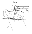
- the door checker 8 for the front door 2 includes a bracket 18 attached to the vehicle body at a position facing the front wall surface of the front door 2, a checker plate 20 supported swingably about a support pin 19 fitted in the bracket 18, and a boxlike holder 21 affixed inside a frontal part of the front door 2 as shown in FIG. 4.
- the holder 21 contains a pair of upper and lower clamping parts 22 and a pair of elastic members 23 forcing the upper and lower clamping parts 22 toward each other as shown in FIG. 5.
- the checker plate 20 has a core 24 made of a steel plate, for example, a sheathing 25 made of synthetic resin covering the core 24 and a stopper 26 provided at an extreme end of the checker plate 20.
- a core 24 made of a steel plate, for example, a sheathing 25 made of synthetic resin covering the core 24 and a stopper 26 provided at an extreme end of the checker plate 20.
- the upper and lower clamping parts 22 grasp the checker plate 20 from both top and bottom sides of the checker plate 20 due to biasing forces exerted by the elastic members 23.
- the thickness of the checker plate 20 is varied along a longitudinal direction of the checker plate 20 so that there are formed alternate protruding portions (protuberances) 27a, 27b, 27c and narrowed portions (recesses) 28a, 28b, 28c on the top and bottom sides of checker plate 20.
- the holder 21 slides along the length of the checker plate 20.
- the amount of friction of sliding exerted by the upper and lower clamping parts 22 on top and bottom surfaces of the checker plate 20 due to the biasing forces of the elastic members 23 varies with the opening angle of the front door 2.
- the support pin 19 of the door checker 8 is located at a position offset inward toward the center line of the vehicle body by a specific distance from the location of the hinge pin 17 as shown in the plan view of FIG. 4. Therefore, as the occupant swings the front door 2 about the hinge pins 17 from the closed position shown by solid lines in FIG. 4 to the open position shown by dot-and-dash lines, and vice versa, the holder 21 moves together with the front door 2 and the checker plate 20 swings about the support pin 19 as shown by solid and dot-and-dash lines.
- the holder 21 shifts sliding along the length of the checker plate 20 when the occupant swings the front door 2.
- the upper and lower clamping parts 22 contained in the holder 21 slide over the protuberances 27a, 27b, 27c toward the successive recesses 28a, 28b, 28c formed on the top and bottom surfaces of the checker plate 20.
- sloping surfaces of the individual recesses 28a, 28b, 28c force the upper and lower clamping parts 22 upward and downward, compressing the upper and lower elastic members 23, respectively. Consequently, there occurs friction of sliding corresponding to the biasing forces exerted by the elastic members 23.
- the biasing forces of the elastic members 23 act in directions in which the upper and lower clamping parts 22 are caused to drop into the individual recesses 28a, 28b, 28c.
- the door checker 9 for the rear door 4 includes a bracket 18 attached to the vehicle body at a position facing the rear wall surface of the rear door 4, a checker plate 20 supported swingably about a support pin 19 fitted in the bracket 18, and a boxlike holder 21 affixed inside a rear part of the rear door 4 as shown in FIG. 6.
- the holder 21 contains a pair of upper and lower clamping parts 22 and a pair of elastic members 23 forcing the upper and lower clamping parts 22 toward each other as shown in FIG. 7.
- the checker plate 20 of the door checker 9 for the rear door 4 differs from the checker plate 20 of the door checker 8 for the front door 2 mainly in that a pair of protuberances 27c (upper and lower) formed close to an extreme end of the checker plate 20 widens toward a stopper 26 forming a large-diameter portion 29 at a terminal part of the checker plate 20 without forming any recesses 28c.
- the checker plate 20 of the door checker 9 for the rear door 4 is otherwise constructed generally in the same fashion as the checker plate 20 of the door checker 8 for the front door 2. Also, the door checker 9 for the rear door 4 functions in a similar way as the door checker 8 for the front door 2.
- the occupant If an occupant on a rear seat intends to open the rear door 4 from the closed position, the occupant first undoes the door lock 5 to unlock the front door 2 and opens the front door 2 to a specific angle. Then, after releasing the upper and lower door locks 6, 7 of the rear door 4, the occupant opens the rear door 4 while holding the inner door handle 14 such that the front end of the rear door 4 swings outward from the vehicle body.
- the door checker 8 for the front door 2 is constructed such that when the front door 2 reaches a position of its minimum opening angle ⁇ 1 located slightly on the outside of a swing trajectory ⁇ of the front end of the rear door 4, the clamping parts 22 of the door checker 8 reach the location of the first recesses 28a (among the first to third recesses 28a, 28b, 28c) formed on the checker plate 20 of the door checker 8 closest to the support pin 19, whereby the front door 2 is held at the minimum opening angle ⁇ 1 as shown in FIG. 8.
- the front door 2 When the front door 2 is further opened and the clamping parts 22 reach the location of the second recesses 28b situated at about the middle of the length of the checker plate 20, the front door 2 is held at its medium opening angle ⁇ 2 which is convenient for a front seat occupant to get into and out of the vehicle. Then, when the front door 2 is further opened and the clamping parts 22 reach the location of the third recesses 28c situated near the extreme end of the checker plate 20, the front door 2 is held at its maximum opening angle ⁇ 3.
- the door checker 9 for the rear door 4 is constructed such that when the rear door 4 reaches a position of its minimum opening angle located slightly on the outside of a swing trajectory ⁇ of the rear end of the front door 2, the clamping parts 22 of the door checker 9 reach the location of the first recesses 28a formed on the checker plate 20 of the door checker 9 closest to the support pin 19, whereby the rear door 4 is held at the minimum opening angle.
- the rear door 4 is further opened and the clamping parts 22 reach the location of the second recesses 28b formed on the checker plate 20, the rear door 4 is held at its medium opening angle which is convenient for a rear seat occupant to get into and out of the vehicle.
- the rear door 4 is further opened and the clamping parts 22 reach the location of the large-diameter portion 29 situated near the extreme end of the checker plate 20, the rear door 4 is held at its maximum opening angle.
- the aforementioned side door structure in which the openings formed in each side wall of the vehicle body are covered by the front door 2 swingably supported by the upper and lower door hinges 1 located at the front end of the front door 2 and by the rear door 4 swingably supported by the upper and lower door hinges 3 located at the rear end of the rear door 4, is provided with the door checker 8 for holding the front door 2 in its open position which is located on the outside of but close to the swing trajectory ⁇ of the front end of the rear door 4 as shown in FIG. 8.
- This structure is advantageous in that the rear door 4 can be opened with ease and safety.
- the rear door 4 Before opening the rear door 4, the occupant slightly opens the front door 2 up to a point where the door checker 8 holds the front door 2 outside but close to the swing trajectory ⁇ of the front end of the rear door 4. As a result, the rear door 4 can be opened without interfering with the rear end of the front door 2. Therefore, the rear seat occupant can open the rear door 4 with ease and safety without the need to take such intricate and painstaking action as stretching out to the front door 2 and opening it unnecessarily widely when getting out of the vehicle.
- the door checker 8 holds the front door 2 at three (first to third) positions.
- the first front door hold position at the minimum opening angle ⁇ 1 where the door checker 8 holds the front door 2 when the clamping parts 22 have reached the location of the first recesses 28a formed on the checker plate 20 of the door checker 8 closest to the support pin 19 is located on the outside of but close to the swing trajectory ⁇ of the front end of the rear door 4.
- the door checker 8 holds the front door 2 at the position corresponding to the minimum opening angle ⁇ 1 when the occupant slightly opens the front door 2 before opening the rear door 4. This arrangement enables the occupant to open the rear door 4 without causing the front end of the rear door 4 to interfere with the rear end of the front door 2.
- the second front door hold position where the door checker 8 holds the front door 2 when the clamping parts 22 have reached the location of the second recesses 28b at about the middle of the length of the checker plate 20 is located at a position corresponding to the medium opening angle ⁇ 2 convenient for the front seat occupant to get into and out of the vehicle
- the third front door hold position where the door checker 8 holds the front door 2 when the clamping parts 22 have reached the location of the third recesses 28c near the extreme end of the checker plate 20 is located at a position corresponding to the maximum opening angle ⁇ 3.
- This arrangement is advantageous in that the front seat occupant can easily get into and out of the vehicle with the front door 2 held at the medium opening angle ⁇ 2 of the front door 2 and luggage can be easily loaded into and unloaded from the vehicle interior with the front door 2 held at the maximum opening angle ⁇ 3.
- the door checker 8 holds the front door 2 at the three hold positions in this embodiment
- the invention is not limited thereto but may be modified in various ways.
- three or more front door hold positions may be provided on the outside of the minimum opening angle ⁇ 1 or only one front door hold position may be provided on the outside of the minimum opening angle ⁇ 1.
- the position of the minimum opening angle at which the door checker 9 holds the rear door 4 when the clamping parts 22 have reached the location of the first recesses 28a formed on the checker plate 20 of the door checker 9 closest to the support pin 19 is located slightly on the outside of the swing trajectory ⁇ of the rear end of the front door 2.
- This arrangement is advantageous in that it effectively prevents the front door 2 from interfering with the rear door 4 when the occupant opens and closes the front door 2 with the rear door 4 held at its minimum opening angle.
- a rear door hold position where the door checker 9 holds the rear door 4 when the clamping parts 22 have reached the location of the second recesses 28b formed on the checker plate 20 is located at a position corresponding to the medium opening angle convenient for the rear seat occupant to get into and out of the vehicle.
- This arrangement permits the rear seat occupant to easily get into and out of the vehicle with the rear door 4 held at the medium opening angle.
- a rear door hold position where the door checker 9 holds the rear door 4 when the clamping parts 22 have reached the location of the large-diameter portion 29 formed near the extreme end of the checker plate 20 is located at a position corresponding to the maximum opening angle of the rear door 4. This is advantageous in that the luggage can be easily loaded into and unloaded from the vehicle interior with the rear door 4 opened up to the maximum opening angle.
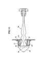
- the clamping parts 22 of the door checker 9 are situated on the large-diameter portion 29 as shown in FIG. 10, the elastic members 23 are compressed so much that a large amount of elastic strain energy is stored in the elastic members 23. Therefore, if the rear door 4 is moved from the maximum opening angle in its closing direction even by a small amount, the clamping parts 22 slide along sloping surfaces of the protuberances 27c, which widen toward the extreme end of the checker plate 20, thereby producing a large amount of assisting force to bias the rear door 4 in the closing direction.
- the rear seat occupant can close the rear door 4 from its maximum opening angle relatively easily, although it is generally rather difficult for reasons related to the human physical structure for the rear seat occupant to apply a large force to the rear door 4 in its closing direction when closing it from the maximum opening angle by holding the inner door handle 14.
- the inner door handle 14 used for opening and closing the rear door 4 is located a specific distance W to the rear of the vehicle body from the front end of the rear door 4.
- This arrangement is advantageous for the rear seat occupant when closing the rear door 4 from its maximum open position shown in FIG. 10. Specifically, the rear seat occupant can easily swing the rear door 4 from the open position to the closed position while holding the inner door handle 14 in a natural posture without the need to stretch the arm for gripping the inner door handle 14.
- the door checker 9 is located below the door hinges 3 swingably supporting the rear door 4 in the embodiment.
- This arrangement makes it possible to determine the location of the door checker 9 with a large degree of freedom, so that the door checker 9 can be installed at a proper position.
- a door checker is generally located between upper and lower door hinges fixed to the rear end of the rear door, this ordinary arrangement provides a considerably limited degree of freedom in the location of the door checker due to limitations in space available between the upper and lower door hinges.
- a sufficient space is available below the door hinges 3, so that the arrangement of the embodiment makes it possible to install the door checker 9 with a sufficiently large degree of freedom in its location.
- the checker plate 20 having an increased overall length, and thus having a large moving stroke, can be installed in the aforementioned space below the door hinges 3 of the rear door 4. This is advantageous in that the maximum opening angle of the rear door 4 restricted by the door checker 9 can be increased.
- the hinge pin 12 of each door hinge 3 affixed to the rear door 4 is inclined as viewed from the front of the vehicle so that the upper end of the hinge pin 12 is located slightly inward toward the center line of the vehicle body, and the hinge pin 12 of each door hinge 3 is inclined so that the upper end of the hinge pin 12 is located slightly to the rear of the vehicle body in side view.
- This arrangement is advantageous in that the rear door 4 can be opened with a small force while avoiding interference between the front end of the rear door 4 and the rear end of the front door 2 and held at an open position of a specific opening angle by means of the door checker 9 which exerts a small restraining force on the rear door 4.
- each door hinge 3 of the rear door 4 is inclined such that the upper end of the hinge pin 12 is located slightly inward toward the center line of the vehicle body as stated above, it is possible to prevent an upper portion of the rear door 4 from being greatly shifted towards inward from the axis line 120 of the hinge pin 12. Also, when swinging the rear door 4 from the closed position to the open position about the hinge pins 12, it is possible to prevent the front end of the rear door 4 from shifting frontward too much. Compared to the earlier-mentioned example of the conventional side door structure shown in FIG.
- each door hinge 3 of the rear door 4 is inclined so that the upper end of the hinge pin 12 is located slightly to the rear of the vehicle body in side view, it is possible to reduce the length L of an arm of moment acting on the rear door 4 in its closing direction about the axis line 120 of the hinge pins 12 passing through the center of gravity G of the rear door 4 due to its own weight M, compared to a case where the hinge pin 12 of each door hinge 3 is vertically mounted in side view. This makes it possible to effectively reduce a swinging force needed in an initial stage of opening the rear door 4.
- FIG. 11 shows the side door structure as viewed along the axial direction of the hinge pins 12, that is, as if cut by a plane intersecting the axis line 120 of the hinge pins 12 at right angles thereto.
- the axis line 120 of the hinge pins 12 is offset so much from the location of the door checker 9 that a sufficient distance S can be ensured between the locations of the hinge pins 12 and the location of the door checker 9 as viewed along the axis line 120. It is therefore possible to obtain a large resisting moment which is given as the product of the restraining force exerted by the door checker 9 when the rear door 4 is opened or closed and the aforementioned distance S. Consequently, the door checker 9 can hold the rear door 4 at specific opening angles in a stable fashion even when the restraining force exerted by the door checker 9 is small.
- FIG. 13 is a side view showing an alternative side door structure in one varied form of the foregoing embodiment.
- This variation of the embodiment applied to a vehicle in which rear doors 4 are located at the front of wheel arches (curved exterior portions of left and right tire houses) 30 for rear wheels, is constructed such that a door checker 9 for each rear door 4 is located at a position offset frontward from the locations of hinge pins 12 of door hinges 3.
- This structure is advantageous in that the door checker 9 can be installed at a proper position and effectively produce a specific resisting moment during the opening of the rear door 4 while avoiding interference between the wheel arch 30 and the door checker 9.
- a side door structure of the invention is applicable to a vehicle of which side openings are covered by a front door swingably supported by a door hinge located at the front of the front door and by a rear door swingably supported by a door hinge located at the rear of the rear door.
- the side door structure includes a door checker for holding the front door at an open position situated on the outside of but close to a swing trajectory of the rear door.
- the door checker of this side door structure holds the front door at the open position situated slightly on the outside of the swing trajectory of the rear door. This structure effectively prevents a front end of the rear door from interfering with a rear end of the front door when an occupant opens the rear door.
- the side door structure may be such that the door checker can hold the front door at multiple open positions, and the open position where the front door is held at a minimum opening angle is situated on the outside of but close to the swing trajectory of the rear door.
- the side door structure thus configured can hold the front door at the open position of the aforementioned minimum opening angle situated slightly on the outside of the swing trajectory of the rear door, it is possible to effectively prevent the front end of the rear door from interfering with the rear end of the front door when the occupant opens the rear door.
- the side door structure may be such that the door checker can hold the front door at least at two open positions situated at opening angles larger than the minimum opening angle.
- the side door structure thus configured can hold the front door at the open position of the aforementioned minimum opening angle, it is possible to effectively prevent the front end of the rear door from interfering with the rear end of the front door when the occupant opens the rear door.
- the side door structure can hold the front door at the opening angles larger than the minimum opening angle, a front seat occupant can easily get into and out of the vehicle and luggage can be easily loaded into and unloaded from the vehicle interior.
- the side door structure further includes a door checker for holding the rear door at an open position situated on the outside of but close to a swing trajectory of the front door.
- the door checker for the rear door of this side door structure holds the rear door at the open position situated slightly on the outside of the swing trajectory of the front door. This structure effectively prevents the rear end of the front door from interfering with the front end of the rear door when the occupant opens the front door.
- the door checker for the front door holds it at the aforementioned open position situated slightly on the outside of the swing trajectory of the rear door before the occupant opens the rear door.
- the side door structure of the invention enables the occupant to open the rear door with ease and safety without causing the front end of the rear door to interfere with the rear end of the front door.
Abstract
Description
- The present invention relates to a side door structure applicable to a vehicle body of which side openings are covered by front doors swingably supported by door hinges located at the front of the front doors and by rear doors swingably supported by door hinges located at the rear of the rear doors.
- There exists a conventionally known side door structure of a vehicle of which front doors and rear doors covering side openings in a vehicle body are opened frontward and rearward, respectively, as described in Japanese Unexamined Patent Publication No. 2001-138864, for example. In this side door structure (hereinafter referred to as the two-way opening side door structure), the front doors are swingably supported by door hinges located at the front of the front doors and the rear doors are swingably supported by door hinges located at the rear of the rear doors so that they can be opened frontward and rearward, respectively.
- The two-way opening side door structure of the vehicle disclosed in the above-cited Japanese Unexamined Patent Publication No. 2001-138864 is built as follows. When opening a
rear door 4a, an occupant first undoes a door lock of afront door 2a and opens thefront door 2a to a specific angle as shown by imaginary lines in FIG. 14 to release the front andrear doors rear door 4a from a closed position to an open position. - Generally, upper portions of side doors (front and rear) of the vehicle are inwardly inclined as viewed from the front of the vehicle so that upper ends of the side doors are located more or less inward toward a center line of the vehicle body largely for design-related reasons. When the front and
rear doors hinge pins front door 2a swings slightly rearward whereas a forwardmost part of the upper end of therear door 4a swings slightly frontward in an initial stage of opening therespective doors rear doors hinge pins - In addition, the front and
rear doors front door 2a and a front end of therear door 4a overlap each other by a specific distance OL. Therefore, a swing trajectory of the rear end of thefront door 2a and a swing trajectory of the front end of therear door 4a produced as therespective doors - In this structure, the front end of the
rear door 4a is apt to interfere with the rear end of thefront door 2a when therear door 4a is opened and, therefore, the occupant has to open therear door 4a after widely opening thefront door 2a to prevent this interference between the front andrear doors - This invention is intended to solve the aforementioned problem concerning operational ease of a two-way opening side door structure. Accordingly, it is an object of the invention to provide a two-way opening side door structure of a vehicle capable of holding a rear door at a specific angle in a stable fashion with a simple construction.
- A side door structure of the invention is applicable to a vehicle of which side openings are covered by a front door swingably supported by a door hinge located at the front of the front door and by a rear door swingably supported by a door hinge located at the rear of the rear door. The side door structure includes a door checker for holding the front door at an open position situated on the outside of but close to a swing trajectory of the rear door.
- The door checker of this side door structure holds the front door at the open position situated slightly on the outside of the swing trajectory of the rear door. This structure effectively prevents a front end of the rear door from interfering with a rear end of the front door when an occupant opens the rear door.
- These and other objects, features and advantages of the invention will become more apparent upon reading the following detailed description along with the accompanying drawings.
-
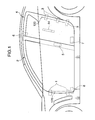
- FIG. 1 is a side view showing a side door structure of a vehicle according to a specific embodiment of the invention;
- FIG. 2 is a plan view showing the side door structure of FIG. 1;
- FIG. 3 is an explanatory diagram showing how a rear door is supported as viewed from the front of the vehicle;
- FIG. 4 is a sectional plan view showing a specific construction of a door checker for a front door;
- FIG. 5 is a sectional side view showing the construction of the door checker for the front door;
- FIG. 6 is a sectional plan view showing a specific construction of a door checker for the rear door;
- FIG. 7 is a sectional side view showing the construction of the door checker for the rear door;
- FIG. 8 is an explanatory diagram showing how the front door swings as it is opened and closed;
- FIG. 9 is an explanatory diagram showing a state in which the rear door is opened to its maximum opening angle;
- FIG. 10 is an explanatory diagram showing a state of the door checker for the rear door as it is opened to the maximum opening angle;
- FIG. 11 is an explanatory diagram showing how the front door and the rear door swing when opened and closed;
- FIG. 12 is an explanatory side view of the front door and the rear door;
- FIG. 13 is a side view particularly showing an alternative rear door structure in one varied form of the embodiment; and
- FIG. 14 is an explanatory diagram showing an example of a conventional side door structure of a vehicle.
-
- FIGS. 1 and 2 are diagrams showing a side door structure of a vehicle according to a specific embodiment of the invention. The side door structure includes left and right
front doors 2 each supported by a pair of upper andlower door hinges 1 located at their front ends and left and rightrear doors 4 each supported by a pair of upper andlower door hinges 3 located at their rear ends. The front andrear doors respective door hinges front doors 2 are opened frontward and therear doors 4 are opened rearward. - The
front door 2 on each side of the vehicle is retained in the closed position as it is interlocked with therear door 4 by adoor lock 5 which includes adoor latch 51 provided at a rear end of thefront door 2 and astriker 52 provided at a front end of therear door 4. On the other hand, therear door 4 on each side of the vehicle is retained in the closed position by a pair of upper andlower door locks rear door 4 and the vehicle body. There is provided adoor checker 8 at a lower front position of thefront door 2 for holding thefront door 2 at a fixed position when it has reached a specific opening angle. Likewise, there is provided adoor checker 9 at a lower rear position of therear door 4 for holding therear door 4 at a fixed position when it has reached a specific opening angle. - The
door hinges 3 supporting therear door 4 each include ametallic hinge leaf 10 affixed to a rear wall surface of therear door 4, ametallic hinge leaf 11 affixed to a rear side of a peripheral surface of the rear opening formed in the vehicle body, and ahinge pin 12 joining thehinge leaves rear door 4 while holding aninner door handle 14 located a specific distance rearward from the front end of therear door 4. Therear door 4 swings between its closed and open positions about thehinge pins 12 of the upper andlower door hinges 3. The upper andlower door hinges 3 are mounted in such a way that anaxis line 120 of eachhinge pin 12 is inclined sideways as viewed from the front of the vehicle so that an upper end of eachhinge pin 12 is located slightly inward toward a center line of the vehicle body as shown in FIG. 3 and theaxis line 120 of eachhinge pin 12 is inclined so that the upper end of eachhinge pin 12 is located slightly to the rear of the vehicle body in side view as shown in FIG. 1. - Likewise, the
door hinges 1 supporting thefront door 2 each include ametallic hinge leaf 15 affixed to a front wall surface of thefront door 2, ametallic hinge leaf 16 affixed to a frontal part of a peripheral surface of the front opening formed in the vehicle body, and ahinge pin 17 joining thehinge leaves front door 2 swings between its closed and open positions about thehinge pins 17 of the upper andlower door hinges 1. Like thedoor hinges 3 of therear door 4, the upper andlower door hinges 1 supporting thefront door 2 are mounted in such a way that anaxis line 170 of eachhinge pin 17 is inclined sideways as viewed from the front of the vehicle so that an upper end of eachhinge pin 17 is located slightly inward toward the center line of the vehicle body and thehinge pin 170 of eachhinge pin 17 is oriented generally vertically in side view as shown in FIG. 1. - The
door checker 8 for thefront door 2 includes abracket 18 attached to the vehicle body at a position facing the front wall surface of thefront door 2, achecker plate 20 supported swingably about asupport pin 19 fitted in thebracket 18, and aboxlike holder 21 affixed inside a frontal part of thefront door 2 as shown in FIG. 4. Theholder 21 contains a pair of upper andlower clamping parts 22 and a pair ofelastic members 23 forcing the upper andlower clamping parts 22 toward each other as shown in FIG. 5. - The
checker plate 20 has acore 24 made of a steel plate, for example, a sheathing 25 made of synthetic resin covering thecore 24 and astopper 26 provided at an extreme end of thechecker plate 20. When thechecker plate 20 is set in position through a hole in theholder 21 as illustrated, the upper andlower clamping parts 22 grasp thechecker plate 20 from both top and bottom sides of thechecker plate 20 due to biasing forces exerted by theelastic members 23. The thickness of thechecker plate 20 is varied along a longitudinal direction of thechecker plate 20 so that there are formed alternate protruding portions (protuberances) 27a, 27b, 27c and narrowed portions (recesses) 28a, 28b, 28c on the top and bottom sides ofchecker plate 20. - As the occupant opens or closes the
front door 2, theholder 21 slides along the length of thechecker plate 20. In thedoor checker 8 constructed as described above, the amount of friction of sliding exerted by the upper andlower clamping parts 22 on top and bottom surfaces of thechecker plate 20 due to the biasing forces of theelastic members 23 varies with the opening angle of thefront door 2. - The
support pin 19 of thedoor checker 8 is located at a position offset inward toward the center line of the vehicle body by a specific distance from the location of thehinge pin 17 as shown in the plan view of FIG. 4. Therefore, as the occupant swings thefront door 2 about thehinge pins 17 from the closed position shown by solid lines in FIG. 4 to the open position shown by dot-and-dash lines, and vice versa, theholder 21 moves together with thefront door 2 and thechecker plate 20 swings about thesupport pin 19 as shown by solid and dot-and-dash lines. Since a supporting point (or an axis line of the support pin 19) about which thechecker plate 20 swings is offset from a supporting point (or an axis line of the hinge pin 17) about which thefront door 2 swings as described above, theholder 21 shifts sliding along the length of thechecker plate 20 when the occupant swings thefront door 2. - When the
holder 21 slides along thechecker plate 20, the upper andlower clamping parts 22 contained in theholder 21 slide over theprotuberances successive recesses checker plate 20. During this sliding process, sloping surfaces of theindividual recesses lower clamping parts 22 upward and downward, compressing the upper and lowerelastic members 23, respectively. Consequently, there occurs friction of sliding corresponding to the biasing forces exerted by theelastic members 23. The biasing forces of theelastic members 23 act in directions in which the upper andlower clamping parts 22 are caused to drop into theindividual recesses parts 22 have dropped into any pair of theserecesses front door 2 is not pushed further outward in its opening action, the upper andlower clamping parts 22 pushed by theelastic members 23 exert a particular restraining force on thechecker plate 20, so that thefront door 2 is kept at an opening angle corresponding to which recesses 28a, 28b, 28c the clampingparts 22 have dropped in. - Likewise, the
door checker 9 for therear door 4 includes abracket 18 attached to the vehicle body at a position facing the rear wall surface of therear door 4, achecker plate 20 supported swingably about asupport pin 19 fitted in thebracket 18, and aboxlike holder 21 affixed inside a rear part of therear door 4 as shown in FIG. 6. Theholder 21 contains a pair of upper andlower clamping parts 22 and a pair ofelastic members 23 forcing the upper andlower clamping parts 22 toward each other as shown in FIG. 7. - The
checker plate 20 of thedoor checker 9 for therear door 4 differs from thechecker plate 20 of thedoor checker 8 for thefront door 2 mainly in that a pair ofprotuberances 27c (upper and lower) formed close to an extreme end of thechecker plate 20 widens toward astopper 26 forming a large-diameter portion 29 at a terminal part of thechecker plate 20 without forming anyrecesses 28c. Thechecker plate 20 of thedoor checker 9 for therear door 4 is otherwise constructed generally in the same fashion as thechecker plate 20 of thedoor checker 8 for thefront door 2. Also, thedoor checker 9 for therear door 4 functions in a similar way as thedoor checker 8 for thefront door 2. - If an occupant on a rear seat intends to open the
rear door 4 from the closed position, the occupant first undoes thedoor lock 5 to unlock thefront door 2 and opens thefront door 2 to a specific angle. Then, after releasing the upper andlower door locks rear door 4, the occupant opens therear door 4 while holding theinner door handle 14 such that the front end of therear door 4 swings outward from the vehicle body. - When the front and
rear doors doors door checkers respective doors - More specifically, the
door checker 8 for thefront door 2 is constructed such that when thefront door 2 reaches a position of its minimum opening angle 1 located slightly on the outside of a swing trajectory α of the front end of therear door 4, the clampingparts 22 of thedoor checker 8 reach the location of thefirst recesses 28a (among the first tothird recesses checker plate 20 of thedoor checker 8 closest to thesupport pin 19, whereby thefront door 2 is held at the minimum opening angle 1 as shown in FIG. 8. When thefront door 2 is further opened and the clampingparts 22 reach the location of thesecond recesses 28b situated at about the middle of the length of thechecker plate 20, thefront door 2 is held at its medium opening angle 2 which is convenient for a front seat occupant to get into and out of the vehicle. Then, when thefront door 2 is further opened and the clampingparts 22 reach the location of thethird recesses 28c situated near the extreme end of thechecker plate 20, thefront door 2 is held at its maximum opening angle 3. - On the other hand, the
door checker 9 for therear door 4 is constructed such that when therear door 4 reaches a position of its minimum opening angle located slightly on the outside of a swing trajectory β of the rear end of thefront door 2, the clampingparts 22 of thedoor checker 9 reach the location of thefirst recesses 28a formed on thechecker plate 20 of thedoor checker 9 closest to thesupport pin 19, whereby therear door 4 is held at the minimum opening angle. When therear door 4 is further opened and the clampingparts 22 reach the location of thesecond recesses 28b formed on thechecker plate 20, therear door 4 is held at its medium opening angle which is convenient for a rear seat occupant to get into and out of the vehicle. Then, when therear door 4 is further opened and the clampingparts 22 reach the location of the large-diameter portion 29 situated near the extreme end of thechecker plate 20, therear door 4 is held at its maximum opening angle. - The aforementioned side door structure, in which the openings formed in each side wall of the vehicle body are covered by the
front door 2 swingably supported by the upper and lower door hinges 1 located at the front end of thefront door 2 and by therear door 4 swingably supported by the upper and lower door hinges 3 located at the rear end of therear door 4, is provided with thedoor checker 8 for holding thefront door 2 in its open position which is located on the outside of but close to the swing trajectory α of the front end of therear door 4 as shown in FIG. 8. This structure is advantageous in that therear door 4 can be opened with ease and safety. - Before opening the
rear door 4, the occupant slightly opens thefront door 2 up to a point where thedoor checker 8 holds thefront door 2 outside but close to the swing trajectory α of the front end of therear door 4. As a result, therear door 4 can be opened without interfering with the rear end of thefront door 2. Therefore, the rear seat occupant can open therear door 4 with ease and safety without the need to take such intricate and painstaking action as stretching out to thefront door 2 and opening it unnecessarily widely when getting out of the vehicle. - In the present embodiment, the
door checker 8 holds thefront door 2 at three (first to third) positions. The first front door hold position at the minimum opening angle 1 where thedoor checker 8 holds thefront door 2 when the clampingparts 22 have reached the location of thefirst recesses 28a formed on thechecker plate 20 of thedoor checker 8 closest to thesupport pin 19 is located on the outside of but close to the swing trajectory α of the front end of therear door 4. In this structure, thedoor checker 8 holds thefront door 2 at the position corresponding to the minimum opening angle 1 when the occupant slightly opens thefront door 2 before opening therear door 4. This arrangement enables the occupant to open therear door 4 without causing the front end of therear door 4 to interfere with the rear end of thefront door 2. - The second front door hold position where the
door checker 8 holds thefront door 2 when the clampingparts 22 have reached the location of thesecond recesses 28b at about the middle of the length of thechecker plate 20 is located at a position corresponding to the medium opening angle 2 convenient for the front seat occupant to get into and out of the vehicle, and the third front door hold position where thedoor checker 8 holds thefront door 2 when the clampingparts 22 have reached the location of thethird recesses 28c near the extreme end of thechecker plate 20 is located at a position corresponding to the maximum opening angle 3. This arrangement is advantageous in that the front seat occupant can easily get into and out of the vehicle with thefront door 2 held at the medium opening angle 2 of thefront door 2 and luggage can be easily loaded into and unloaded from the vehicle interior with thefront door 2 held at the maximum opening angle 3. - While the
door checker 8 holds thefront door 2 at the three hold positions in this embodiment, the invention is not limited thereto but may be modified in various ways. For example, three or more front door hold positions may be provided on the outside of the minimum opening angle 1 or only one front door hold position may be provided on the outside of the minimum opening angle 1. - In the aforementioned embodiment of the invention, the position of the minimum opening angle at which the
door checker 9 holds therear door 4 when the clampingparts 22 have reached the location of thefirst recesses 28a formed on thechecker plate 20 of thedoor checker 9 closest to thesupport pin 19 is located slightly on the outside of the swing trajectory β of the rear end of thefront door 2. This arrangement is advantageous in that it effectively prevents thefront door 2 from interfering with therear door 4 when the occupant opens and closes thefront door 2 with therear door 4 held at its minimum opening angle. - According to the embodiment, a rear door hold position where the
door checker 9 holds therear door 4 when the clampingparts 22 have reached the location of thesecond recesses 28b formed on thechecker plate 20 is located at a position corresponding to the medium opening angle convenient for the rear seat occupant to get into and out of the vehicle. This arrangement permits the rear seat occupant to easily get into and out of the vehicle with therear door 4 held at the medium opening angle. In addition, a rear door hold position where thedoor checker 9 holds therear door 4 when the clampingparts 22 have reached the location of the large-diameter portion 29 formed near the extreme end of thechecker plate 20 is located at a position corresponding to the maximum opening angle of therear door 4. This is advantageous in that the luggage can be easily loaded into and unloaded from the vehicle interior with therear door 4 opened up to the maximum opening angle. - As illustrated in the foregoing discussion of the embodiment, there is formed the large-
diameter portion 29 near the extreme end of thechecker plate 20 of thedoor checker 9 for therear door 4 and, when therear door 4 has reached its maximum opening angle shown in FIG. 9, the clampingparts 22 contained in theholder 21 slide onto the large-diameter portion 29 of thechecker plate 20 as shown in FIG. 10, whereby and thedoor checker 9 holds therear door 4 at the maximum opening angle. This arrangement is advantageous in that the occupant can easily close therear door 4 from its maximum opening angle. - More specifically, when the clamping
parts 22 of thedoor checker 9 are situated on the large-diameter portion 29 as shown in FIG. 10, theelastic members 23 are compressed so much that a large amount of elastic strain energy is stored in theelastic members 23. Therefore, if therear door 4 is moved from the maximum opening angle in its closing direction even by a small amount, the clampingparts 22 slide along sloping surfaces of theprotuberances 27c, which widen toward the extreme end of thechecker plate 20, thereby producing a large amount of assisting force to bias therear door 4 in the closing direction. Therefore, the rear seat occupant can close therear door 4 from its maximum opening angle relatively easily, although it is generally rather difficult for reasons related to the human physical structure for the rear seat occupant to apply a large force to therear door 4 in its closing direction when closing it from the maximum opening angle by holding theinner door handle 14. - According to the embodiment, the
inner door handle 14 used for opening and closing therear door 4 is located a specific distance W to the rear of the vehicle body from the front end of therear door 4. This arrangement is advantageous for the rear seat occupant when closing therear door 4 from its maximum open position shown in FIG. 10. Specifically, the rear seat occupant can easily swing therear door 4 from the open position to the closed position while holding theinner door handle 14 in a natural posture without the need to stretch the arm for gripping theinner door handle 14. - Also, the
door checker 9 is located below the door hinges 3 swingably supporting therear door 4 in the embodiment. This arrangement makes it possible to determine the location of thedoor checker 9 with a large degree of freedom, so that thedoor checker 9 can be installed at a proper position. Specifically, while a door checker is generally located between upper and lower door hinges fixed to the rear end of the rear door, this ordinary arrangement provides a considerably limited degree of freedom in the location of the door checker due to limitations in space available between the upper and lower door hinges. By comparison, a sufficient space is available below the door hinges 3, so that the arrangement of the embodiment makes it possible to install thedoor checker 9 with a sufficiently large degree of freedom in its location. Also, thechecker plate 20 having an increased overall length, and thus having a large moving stroke, can be installed in the aforementioned space below the door hinges 3 of therear door 4. This is advantageous in that the maximum opening angle of therear door 4 restricted by thedoor checker 9 can be increased. - In this embodiment, the
hinge pin 12 of eachdoor hinge 3 affixed to therear door 4 is inclined as viewed from the front of the vehicle so that the upper end of thehinge pin 12 is located slightly inward toward the center line of the vehicle body, and thehinge pin 12 of eachdoor hinge 3 is inclined so that the upper end of thehinge pin 12 is located slightly to the rear of the vehicle body in side view. This arrangement is advantageous in that therear door 4 can be opened with a small force while avoiding interference between the front end of therear door 4 and the rear end of thefront door 2 and held at an open position of a specific opening angle by means of thedoor checker 9 which exerts a small restraining force on therear door 4. - Since the
hinge pin 12 of eachdoor hinge 3 of therear door 4 is inclined such that the upper end of thehinge pin 12 is located slightly inward toward the center line of the vehicle body as stated above, it is possible to prevent an upper portion of therear door 4 from being greatly shifted towards inward from theaxis line 120 of thehinge pin 12. Also, when swinging therear door 4 from the closed position to the open position about the hinge pins 12, it is possible to prevent the front end of therear door 4 from shifting frontward too much. Compared to the earlier-mentioned example of the conventional side door structure shown in FIG. 14, in which the hinge pins 12a are mounted in a vertical position as viewed from the side of the vehicle, it is possible to significantly decrease an area "A" of overlap between the rear end of thefront door 2 and the front end of therear door 4 as viewed along an axial direction of the hinge pins 12 which are inclined as stated above, as shown in FIG. 11. This arrangement effectively prevents interference between thefront door 2 and therear door 4. - Also, since the
hinge pin 12 of eachdoor hinge 3 of therear door 4 is inclined so that the upper end of thehinge pin 12 is located slightly to the rear of the vehicle body in side view, it is possible to reduce the length L of an arm of moment acting on therear door 4 in its closing direction about theaxis line 120 of the hinge pins 12 passing through the center of gravity G of therear door 4 due to its own weight M, compared to a case where thehinge pin 12 of eachdoor hinge 3 is vertically mounted in side view. This makes it possible to effectively reduce a swinging force needed in an initial stage of opening therear door 4. Moreover, since the moment acting on therear door 4 in its closing direction becomes zero at a point where therear door 4 is opened to a specific angle which is smaller than 90 degrees and an acting direction of the weight M of therear door 4 matches a direction of inclination of thehinge pin 12 of eachdoor hinge 3 as shown in FIG. 11, it is also possible to effectively reduce a swinging force needed in a final stage of opening therear door 4. While the own weight M of therear door 4 passing through its center of gravity G acts in a vertical direction, a line showing the direction in which the weight M of therear door 4 acts is inclined as illustrated in FIG. 11. This is because FIG. 11 shows the side door structure as viewed along the axial direction of the hinge pins 12, that is, as if cut by a plane intersecting theaxis line 120 of the hinge pins 12 at right angles thereto. - When the
door checker 9 is located more inward toward the center line of the vehicle body than the hinge pins 12 which are inclined such that their upper ends are located slightly inward toward the center line of the vehicle body as shown in FIG. 3, theaxis line 120 of the hinge pins 12 is offset so much from the location of thedoor checker 9 that a sufficient distance S can be ensured between the locations of the hinge pins 12 and the location of thedoor checker 9 as viewed along theaxis line 120. It is therefore possible to obtain a large resisting moment which is given as the product of the restraining force exerted by thedoor checker 9 when therear door 4 is opened or closed and the aforementioned distance S. Consequently, thedoor checker 9 can hold therear door 4 at specific opening angles in a stable fashion even when the restraining force exerted by thedoor checker 9 is small. - FIG. 13 is a side view showing an alternative side door structure in one varied form of the foregoing embodiment. This variation of the embodiment, applied to a vehicle in which
rear doors 4 are located at the front of wheel arches (curved exterior portions of left and right tire houses) 30 for rear wheels, is constructed such that adoor checker 9 for eachrear door 4 is located at a position offset frontward from the locations of hinge pins 12 of door hinges 3. This structure is advantageous in that thedoor checker 9 can be installed at a proper position and effectively produce a specific resisting moment during the opening of therear door 4 while avoiding interference between thewheel arch 30 and thedoor checker 9. - In summary, a side door structure of the invention is applicable to a vehicle of which side openings are covered by a front door swingably supported by a door hinge located at the front of the front door and by a rear door swingably supported by a door hinge located at the rear of the rear door. The side door structure includes a door checker for holding the front door at an open position situated on the outside of but close to a swing trajectory of the rear door.
- The door checker of this side door structure holds the front door at the open position situated slightly on the outside of the swing trajectory of the rear door. This structure effectively prevents a front end of the rear door from interfering with a rear end of the front door when an occupant opens the rear door.
- According to one feature of the invention, the side door structure may be such that the door checker can hold the front door at multiple open positions, and the open position where the front door is held at a minimum opening angle is situated on the outside of but close to the swing trajectory of the rear door.
- As the side door structure thus configured can hold the front door at the open position of the aforementioned minimum opening angle situated slightly on the outside of the swing trajectory of the rear door, it is possible to effectively prevent the front end of the rear door from interfering with the rear end of the front door when the occupant opens the rear door.
- According to another feature of the invention, the side door structure may be such that the door checker can hold the front door at least at two open positions situated at opening angles larger than the minimum opening angle.
- As the side door structure thus configured can hold the front door at the open position of the aforementioned minimum opening angle, it is possible to effectively prevent the front end of the rear door from interfering with the rear end of the front door when the occupant opens the rear door. In addition, since the side door structure can hold the front door at the opening angles larger than the minimum opening angle, a front seat occupant can easily get into and out of the vehicle and luggage can be easily loaded into and unloaded from the vehicle interior.
- According to still another feature of the invention, the side door structure further includes a door checker for holding the rear door at an open position situated on the outside of but close to a swing trajectory of the front door.
- The door checker for the rear door of this side door structure holds the rear door at the open position situated slightly on the outside of the swing trajectory of the front door. This structure effectively prevents the rear end of the front door from interfering with the front end of the rear door when the occupant opens the front door.
- Overall, the door checker for the front door holds it at the aforementioned open position situated slightly on the outside of the swing trajectory of the rear door before the occupant opens the rear door. Thus, the side door structure of the invention enables the occupant to open the rear door with ease and safety without causing the front end of the rear door to interfere with the rear end of the front door.
- Although the present invention has been fully described by way of example with reference to the accompanying drawings, it is to be understood that various changes and modifications will be apparent to those skilled in the art. Therefore, unless otherwise such changes and modifications depart from the scope of the present invention hereinafter defined, they should be construed as being included therein.
Claims (10)
- A side door structure of a vehicle of which side openings are covered by a front door (2) swingably supported by a door hinge (1) located at the front of the front door (2) and by a rear door (4) swingably supported by a door hinge (3) located at the rear of the rear door (4), said side door structure comprising:a front door checker (8) for holding the front door (2) at an open position situated on the outside of but close to a swing trajectory of the rear door (4).
- The side door structure according to claim 1, wherein the front door checker (8) can hold the front door (2) at multiple open positions, and the open position where the front door (2) is held at a minimum opening angle is situated on the outside of but close to the swing trajectory of the rear door (4).
- The side door structure according to claim 2, wherein the front door checker (8) can hold the front door (2) at least at two open positions situated at opening angles larger than the minimum opening angle.
- The side door structure according to one of claims 1 to 3 further comprising:a rear door checker (9) for holding the rear door (4) at an open position situated on the outside of but close to a swing trajectory of the front door (2).
- The side door structure according to one of the preceding claims, wherein the front door checker (8) includes a bracket (18) fixed to a vehicle body; a holder (21) fixed inside a frontal part of the front door (2); and a front checker plate (20) having one end pivotally mounted on the bracket (18) and the other end (26) and a main body extending between said one end and the other end, extending through an opening formed in the holder (21).
- The side door structure according to one of the preceding claims, wherein said main body portion of the front checker plate (20) has a plurality of protruding portions (27a, 27b) and a plurality of recessed portions (28a, 28b, 28c) along the extending direction of the main body and a clamping member (22) is provided in the holder (21) such that said clamping member (22) has a portion which is in press-contact with the main body of the front checker plate (20).
- The side door structure according to one of the preceding claims, wherein the clamping member (22) is provided at an upper and a lower portions in the holder (21), an elastic member (23) is interposed between the top inner wall of the holder (21) and the upper clamping member(22) and between the bottom inner wall of the holder (21) and the lower clamping member (22) such that said main body of the front checker plate (20) is interposed between the upper clamping member (22) and the lower clamping member (22).
- The side door structure according to one of the preceding claims, wherein the rear door checker (9) includes a bracket (18) fixed to a vehicle body; a holder (21) fixed inside a rear part of the rear door (4); and a rear checker plate (20) having one end pivotally mounted on the bracket (18) and the other end (26) and a main body extending between said one end and the other end, extending I through an opening formed in the holder (21).
- The side door structure according to one of the preceding claims, wherein said main body portion of the rear checker plate (20) has a plurality of protruding portions (27a, 27b, 27c) and a plurality of recessed portions (28a, 28b) along the extending direction of the main body and a clamping member (22) is provided in the holder (21) such that said clamping member (22) has a portion which is in press-contact with the main body of the rear checker plate (20).
- The side door structure according to one of the preceding claims, wherein the clamping member (22) is provided at an upper and a lower portions in the holder (21), an elastic member (23) is interposed between the top inner wall of the holder (21) and the upper clamping member (22) and between the bottom inner wall of the holder (21) and the lower clamping member (22) such that said main body of the rear checker plate (20) is interposed between the upper clamping member (22) and the lower clamping member (22).
Applications Claiming Priority (2)
| Application Number | Priority Date | Filing Date | Title |
|---|---|---|---|
| JP2002321644A JP4165188B2 (en) | 2002-11-05 | 2002-11-05 | Vehicle side door structure |
| JP2002321644 | 2002-11-05 |
Publications (3)
| Publication Number | Publication Date |
|---|---|
| EP1418075A2 true EP1418075A2 (en) | 2004-05-12 |
| EP1418075A3 EP1418075A3 (en) | 2007-05-30 |
| EP1418075B1 EP1418075B1 (en) | 2008-09-24 |
Family
ID=32105435
Family Applications (1)
| Application Number | Title | Priority Date | Filing Date |
|---|---|---|---|
| EP03025360A Expired - Lifetime EP1418075B1 (en) | 2002-11-05 | 2003-11-04 | Side door structure of vehicle |
Country Status (5)
| Country | Link |
|---|---|
| US (1) | US6966600B2 (en) |
| EP (1) | EP1418075B1 (en) |
| JP (1) | JP4165188B2 (en) |
| CN (1) | CN100537285C (en) |
| DE (1) | DE60323720D1 (en) |
Cited By (2)
| Publication number | Priority date | Publication date | Assignee | Title |
|---|---|---|---|---|
| US6979046B2 (en) | 2002-11-05 | 2005-12-27 | Mazda Motor Corporation | Side door structure of vehicle and method of designing the side door structure |
| CZ305204B6 (en) * | 2009-08-25 | 2015-06-10 | Edscha Automotive Kamenice S.R.O. | Door balancer for motor vehicles |
Families Citing this family (13)
| Publication number | Priority date | Publication date | Assignee | Title |
|---|---|---|---|---|
| JP4381889B2 (en) * | 2004-05-26 | 2009-12-09 | 三井金属鉱業株式会社 | Door equipment |
| US7488029B2 (en) * | 2005-12-16 | 2009-02-10 | Ford Global Technologies, Llc | Independently opening doors for an automotive door opening |
| US20090300877A1 (en) * | 2008-06-09 | 2009-12-10 | Wood Matthew J | Device and method of mechanically dampening a hold open rod |
| US8615846B2 (en) * | 2008-06-09 | 2013-12-31 | Marathonnorco Aerospace, Inc. | Mechanically dampening hold open rod |
| DE102010003755A1 (en) * | 2010-04-08 | 2011-10-13 | Bayerische Motoren Werke Aktiengesellschaft | motor vehicle |
| US20120049579A1 (en) * | 2010-09-01 | 2012-03-01 | Gm Global Technology Operations, Inc. | Articulating door hinge |
| US9061569B2 (en) * | 2011-12-21 | 2015-06-23 | Arctic Cat Inc. | Door for recreational off-highway vehicle |
| JP6007745B2 (en) * | 2012-11-20 | 2016-10-12 | アイシン精機株式会社 | Door drive device |
| DE102015214086B4 (en) * | 2015-07-24 | 2023-07-27 | Bayerische Motoren Werke Aktiengesellschaft | Door system for a passenger car with at least two rows of seats |
| US9869119B2 (en) * | 2016-02-29 | 2018-01-16 | Faraday&Future Inc. | Systems and methods for operating vehicle doors |
| JP2019183477A (en) * | 2018-04-09 | 2019-10-24 | トヨタ自動車株式会社 | Side door mounting structure |
| RU2691556C1 (en) * | 2018-08-27 | 2019-06-14 | Николай Николаевич Леухин | Car door opening system (versions) and method of its application |
| GB2577916B (en) * | 2018-10-10 | 2020-10-14 | Ford Global Tech Llc | A door check mechanism |
Citations (1)
| Publication number | Priority date | Publication date | Assignee | Title |
|---|---|---|---|---|
| JP2001138864A (en) | 1999-11-11 | 2001-05-22 | Toyota Autom Loom Works Ltd | Seat belt device of automobile |
Family Cites Families (10)
| Publication number | Priority date | Publication date | Assignee | Title |
|---|---|---|---|---|
| US2043976A (en) * | 1935-02-28 | 1936-06-09 | Rudolph I Schonitzer | Combined door-holding and door-checking device |
| US2915777A (en) * | 1955-09-09 | 1959-12-08 | Lisle W Menzimer | Door holding device |
| US2915778A (en) * | 1956-01-26 | 1959-12-08 | Lisle W Menzimer | Door holding device |
| US2880029A (en) * | 1957-01-23 | 1959-03-31 | Lisle W Menzimer | Door check |
| DE3537304A1 (en) * | 1985-10-19 | 1987-04-23 | Porsche Ag | STRUCTURE FOR CARS |
| US4930836A (en) * | 1988-06-24 | 1990-06-05 | Ford Motor Company | Door assembly for pick-up trucks |
| JP4622094B2 (en) * | 2000-12-14 | 2011-02-02 | マツダ株式会社 | Opening and closing structure of vehicle |
| KR20030016658A (en) * | 2001-08-21 | 2003-03-03 | 현대자동차주식회사 | door checker structure for an automotive vehicle |
| JP3585873B2 (en) * | 2001-08-31 | 2004-11-04 | 理研化機工業株式会社 | Door checker check plate support structure |
| JP3542343B2 (en) * | 2001-10-16 | 2004-07-14 | 理研化機工業株式会社 | Car door checker |
-
2002
- 2002-11-05 JP JP2002321644A patent/JP4165188B2/en not_active Expired - Lifetime
-
2003
- 2003-11-04 CN CNB2003101142552A patent/CN100537285C/en not_active Expired - Lifetime
- 2003-11-04 DE DE60323720T patent/DE60323720D1/en not_active Expired - Lifetime
- 2003-11-04 EP EP03025360A patent/EP1418075B1/en not_active Expired - Lifetime
- 2003-11-05 US US10/700,464 patent/US6966600B2/en not_active Expired - Lifetime
Patent Citations (1)
| Publication number | Priority date | Publication date | Assignee | Title |
|---|---|---|---|---|
| JP2001138864A (en) | 1999-11-11 | 2001-05-22 | Toyota Autom Loom Works Ltd | Seat belt device of automobile |
Cited By (2)
| Publication number | Priority date | Publication date | Assignee | Title |
|---|---|---|---|---|
| US6979046B2 (en) | 2002-11-05 | 2005-12-27 | Mazda Motor Corporation | Side door structure of vehicle and method of designing the side door structure |
| CZ305204B6 (en) * | 2009-08-25 | 2015-06-10 | Edscha Automotive Kamenice S.R.O. | Door balancer for motor vehicles |
Also Published As
| Publication number | Publication date |
|---|---|
| CN1526578A (en) | 2004-09-08 |
| DE60323720D1 (en) | 2008-11-06 |
| EP1418075A3 (en) | 2007-05-30 |
| JP4165188B2 (en) | 2008-10-15 |
| EP1418075B1 (en) | 2008-09-24 |
| JP2004155275A (en) | 2004-06-03 |
| US6966600B2 (en) | 2005-11-22 |
| CN100537285C (en) | 2009-09-09 |
| US20040088823A1 (en) | 2004-05-13 |
Similar Documents
| Publication | Publication Date | Title |
|---|---|---|
| EP1418075B1 (en) | Side door structure of vehicle | |
| US10815705B2 (en) | Vehicle door handle | |
| JP3935020B2 (en) | Lid opening / closing mechanism and vehicle storage device | |
| US6942277B2 (en) | Vehicle door hinge assembly | |
| US6318782B1 (en) | Opening/closing rear component structure of a vehicle | |
| US7918492B2 (en) | Vehicle door belt and cam articulating mechanism | |
| US20060061135A1 (en) | Vehicle door with pivot arm | |
| JP2005088885A (en) | Floor carrier provided with door provided with double hinge mechanism and side frame opening | |
| US20070294860A1 (en) | Vehicle door hinge | |
| EP1405746A3 (en) | Vehicle side-door structure | |
| US6974177B2 (en) | Dual-axis door hinge assembly for vehicles | |
| US6979046B2 (en) | Side door structure of vehicle and method of designing the side door structure | |
| KR20030086806A (en) | 2-way open type console box cover structure for automobile | |
| CN103802893B (en) | Swing type rear baffle detector assembly | |
| WO2003086794A3 (en) | Decklid mechanism for vehicle with retractable top | |
| CN103534428A (en) | Cable connection structure for movable member | |
| JP4376271B2 (en) | Overhead console device | |
| EP1418074B1 (en) | Side door structure of vehicle | |
| JP4304422B2 (en) | Vehicle side door structure | |
| JPS6125572B2 (en) | ||
| JP4073642B2 (en) | Locking device for upper and lower doors for vehicles | |
| JP4165187B2 (en) | Vehicle side door structure | |
| JP2019010937A (en) | Vehicle console device having double door | |
| JP4165189B2 (en) | Vehicle side door structure | |
| KR100857707B1 (en) | Device for opening and closing a covering shelf of vehicle |
Legal Events
| Date | Code | Title | Description |
|---|---|---|---|
| PUAI | Public reference made under article 153(3) epc to a published international application that has entered the european phase |
Free format text: ORIGINAL CODE: 0009012 |
|
| AK | Designated contracting states |
Kind code of ref document: A2 Designated state(s): AT BE BG CH CY CZ DE DK EE ES FI FR GB GR HU IE IT LI LU MC NL PT RO SE SI SK TR |
|
| AX | Request for extension of the european patent |
Extension state: AL LT LV MK |
|
| PUAL | Search report despatched |
Free format text: ORIGINAL CODE: 0009013 |
|
| AK | Designated contracting states |
Kind code of ref document: A3 Designated state(s): AT BE BG CH CY CZ DE DK EE ES FI FR GB GR HU IE IT LI LU MC NL PT RO SE SI SK TR |
|
| AX | Request for extension of the european patent |
Extension state: AL LT LV MK |
|
| RIC1 | Information provided on ipc code assigned before grant |
Ipc: E05C 17/20 20060101ALI20070420BHEP Ipc: B60J 5/04 20060101AFI20040302BHEP Ipc: E05F 1/06 20060101ALI20070420BHEP |
|
| 17P | Request for examination filed |
Effective date: 20070920 |
|
| AKX | Designation fees paid |
Designated state(s): DE |
|
| GRAP | Despatch of communication of intention to grant a patent |
Free format text: ORIGINAL CODE: EPIDOSNIGR1 |
|
| GRAS | Grant fee paid |
Free format text: ORIGINAL CODE: EPIDOSNIGR3 |
|
| GRAA | (expected) grant |
Free format text: ORIGINAL CODE: 0009210 |
|
| AK | Designated contracting states |
Kind code of ref document: B1 Designated state(s): DE |
|
| REF | Corresponds to: |
Ref document number: 60323720 Country of ref document: DE Date of ref document: 20081106 Kind code of ref document: P |
|
| PLBE | No opposition filed within time limit |
Free format text: ORIGINAL CODE: 0009261 |
|
| STAA | Information on the status of an ep patent application or granted ep patent |
Free format text: STATUS: NO OPPOSITION FILED WITHIN TIME LIMIT |
|
| 26N | No opposition filed |
Effective date: 20090625 |
|
| PGFP | Annual fee paid to national office [announced via postgrant information from national office to epo] |
Ref country code: DE Payment date: 20220930 Year of fee payment: 20 |
|
| REG | Reference to a national code |
Ref country code: DE Ref legal event code: R071 Ref document number: 60323720 Country of ref document: DE |