EP1418072A1 - Guide system for guiding window glass of vehicle - Google Patents
Guide system for guiding window glass of vehicle Download PDFInfo
- Publication number
- EP1418072A1 EP1418072A1 EP03256029A EP03256029A EP1418072A1 EP 1418072 A1 EP1418072 A1 EP 1418072A1 EP 03256029 A EP03256029 A EP 03256029A EP 03256029 A EP03256029 A EP 03256029A EP 1418072 A1 EP1418072 A1 EP 1418072A1
- Authority
- EP
- European Patent Office
- Prior art keywords
- guide
- guide rail
- vehicle
- slider
- base
- Prior art date
- Legal status (The legal status is an assumption and is not a legal conclusion. Google has not performed a legal analysis and makes no representation as to the accuracy of the status listed.)
- Granted
Links
- 239000005357 flat glass Substances 0.000 title claims abstract description 38
- 210000000078 claw Anatomy 0.000 claims description 10
- 230000000694 effects Effects 0.000 description 11
- 230000003028 elevating effect Effects 0.000 description 6
- 239000011521 glass Substances 0.000 description 3
- 238000009434 installation Methods 0.000 description 2
- 239000003381 stabilizer Substances 0.000 description 2
- 230000001151 other effect Effects 0.000 description 1
Images


Classifications
-
- B—PERFORMING OPERATIONS; TRANSPORTING
- B60—VEHICLES IN GENERAL
- B60J—WINDOWS, WINDSCREENS, NON-FIXED ROOFS, DOORS, OR SIMILAR DEVICES FOR VEHICLES; REMOVABLE EXTERNAL PROTECTIVE COVERINGS SPECIALLY ADAPTED FOR VEHICLES
- B60J1/00—Windows; Windscreens; Accessories therefor
- B60J1/08—Windows; Windscreens; Accessories therefor arranged at vehicle sides
- B60J1/12—Windows; Windscreens; Accessories therefor arranged at vehicle sides adjustable
- B60J1/16—Windows; Windscreens; Accessories therefor arranged at vehicle sides adjustable slidable
- B60J1/17—Windows; Windscreens; Accessories therefor arranged at vehicle sides adjustable slidable vertically
Definitions
- the present invention relates to a guide system for guiding a window glass of a vehicle, particularly to the guide system for effectively eliminating a play between the glass and a guide rail.
- a conventional guide includes a main member of a guide rail sliding in a groove with a roughly C-shaped cross section, and a shaft rotatably supported on the main guide member and projected from an open portion of a guide rail for holding a window glass (for example, refer to the following references No. 1 to No. 5).
- a pair of the guide rails is disposed in front and rear sides of a door.
- the front guide rail has an opening facing a glass surface
- the rear guide rail has an opening facing the front of the vehicle (for example, refer to the following reference No. 6).
- the rattles inside the guide rail are absorbed by elasticity against a force in an axial direction of the shaft.
- the direction of the force exerted on the shaft changes in a 90 degrees different direction. Therefore, when the conventional guide is mounted on the guide rail with the opening facing the front of the vehicle, the force is exerted in a direction perpendicular to the shaft, thereby causing a risk wherein the guide moves with the rattle in a width direction of the guide rail.
- An object of the first aspect of the invention is to provide a guide suitable for a guide rail with an opening facing at least one of the front and backside of the vehicle.
- an object is as follows.
- the object of the second aspect of the present invention is to provide a guide in which projections of the guide elastically abut against a bottom of the guide rail, thereby absorbing the rattles in a vertical direction of the guide rail.
- an object is as follows.
- the object of the third aspect of the invention is to provide a guide having an elastic member for supporting an elastic force of the projections.
- an object is as follows.
- the object of the fourth aspect of the invention is to provide a guide wherein a notch engages a claw, thereby simplifying an assembly of the guide, and also it is possible to control a sliding amount of a slider relative to the base.
- an object is as follows.
- the object of the fifth aspect of the invention is to provide a guide suitable for a guide rail with an opening facing the front of the vehicle.
- an object is as follows.
- the object of the sixth aspect of the invention is to provide a guide wherein a shaft is rotated in upper and lower directions of the window glass to smoothly raise and lower the window glass. For example, even when the guide rail is slightly curved relative to a moving direction of the vehicle, the shaft is rotated in the upper and lower directions of the window glass, thereby absorbing the curve of the guide rail.
- the rotation of the shaft in the width direction of the vehicle is limited so as not to hinder the function of the guide for preventing and absorbing the rattles of the window glass.
- a guide rail (for example, a backside guide rail) includes the following structure.
- At least one of the base and the slider has a projection elastically projecting toward the inner surface of the inner back wall of the guide rail (for example, the backside guide rail).
- the projection is urged in a direction that the projection projects toward the inner surface of the inner back wall of the guide rail (for example, the backside guide rail) with the elastic member (for example, the first elastic member).
- the characteristics are as follows.
- one of the base and the slider includes a depression.
- the other of the base and the slider includes a claw for connecting the base to the slider when the claw elastically fits into the depression.
- the depression is provided with a stopper at one end thereof for controlling the slider to move toward the outside of the vehicle by abutting against the claw.
- the guide rail for example, the backside guide rail
- the guide rail has the open portion facing the front of the vehicle.
- the characteristics are as follows.
- the shaft is held by the base and mounted to be rotatable only in the upper and lower directions of the window glass.
- Figs. 1-11 show embodiments of the present invention, respectively.
- Fig. 1 is a partial cross sectional view showing a device for raising and lowering a window glass of a vehicle
- Fig. 2 is a side view of a door
- Fig. 3 is a partial cross sectional view showing an installation state of the window glass
- Fig. 4 is a cross sectional view of a backside guide rail
- Fig. 5 is an exploded perspective view of a guide
- Fig. 6 is a plan view of the guide
- Fig. 7 is a side view of the guide
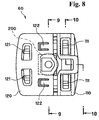
- Fig. 8 is a bottom view of the guide
- Fig. 9 is a cross sectional view taken along 9-9 line in Fig. 8
- Fig. 10 is a cross sectional view taken along 10-10 line in Fig. 8
- Fig. 11 is a cross sectional view showing the installation state of the guide.
- Figs. 1-2 10 denotes the guide for raising and lowering a window glass 20 of the vehicle.
- the elevator device 10 is disposed, for example, on the door 30, and connected to a window regulator (not shown in the figure). Incidentally, the elevator device 10 is not limited to the door 30.
- the elevator device 10 mainly includes the following configuration as shown in Figs. 1-2.
- the door 30 mainly includes the following parts.
- the parts of the door 30 are not limited to the following (1)-(2).
- a pair of the guide rails 40, 50 is disposed at the front and back sides of the door 30.
- the guide rail 40 located at the front side of the door 30 has an opening facing the backside of the vehicle, although it is not shown in the figure.
- the window glass 20 is mounted on the front side guide rail 40 for elevating and lowering through the existing guide, though it is not shown in the figure.
- the guide rail 50 at the backside of the door 30 has an open portion 56 facing the front side of the vehicle, as described later.
- the backside guide rail 50 is located between the outer panel 31 and the inner panel 32, and fixed to the inner panel 32 side.
- the backside guide rail 50 is inclined relative to a moving direction of the vehicle, or is slightly curved. More specifically, the backside guide rail 50 mainly includes the following configuration, as shown in Fig. 4.
- the configuration of the backside guide rail 50 is not limited to the following structure: (1)-(4).
- the guide 60 is mounted and slidable in the backside guide rail 50 between the front and back guide rails 40, 50, and is connected to the bracket 70, as shown in Fig. 1.
- the guide 60 as shown in Figs. 5, 7, mainly includes the following parts.
- the bracket 70 fixes the window glass 20 to the shaft 200, and is curved in an L-shape.
- the main guide member 100 is mounted and slidable in the backside guide rail 50.
- the main guide member 100 mainly includes the following parts.
- the shaft 200 fixes the window glass 20 projecting from the open portion 56 of the backside guide rail 50.
- the shaft 200 as shown in Fig. 9, is held by the base 110, and mounted to be rotatable only in a direction that the window glass 20 is elevated.
- the shaft 200 as shown in Fig. 5, mainly includes the following parts.
- the base 110 as shown in Figs. 5, 11, is one side of parts divided in the width direction of the vehicle, and contacts the inner face of the inner sidewall 52.
- the base 110 as shown in Figs. 5-11, mainly includes the following parts. Incidentally, the parts of the base 110 are not limited to the following (1)-(3).
- the slider 120 as shown in Figs. 5, 11, is the other parts divided in the widthwise direction of the vehicle, and contacts the outer sidewall 53. Also, the slider 120 is held by the base 110 and can slide in the width direction of the vehicle.
- the slider 120 as shown in Figs. 5-11, mainly includes the following parts. Incidentally, the parts of the slider 120 are not limited to the following structure: (1)-(3).
- the shaft connection 160 as shown in Fig. 9, mainly includes the following parts.
- the parts of the shaft connection 160 are not limited to the following structure: (1)-(3).
- the right-and-left movement of the main shaft member 210, as shown in Fig. 6, is also controlled by abutting against the right and left walls of the guide frame 163.
- the first elastic member 130 as shown in Fig. 11, is located between the base 110 and the slider 120, and presses the slider 120 toward the outside direction of the vehicle.
- the first elastic member 130 as shown in Fig. 5, is located across the two projections 121 of the slider 120, and although it is not shown in the figure, the first elastic member 130 urges each projection 121 in the projecting direction toward the inner surface of the inner back wall 51 of the backside guide rail 50.
- Each of the second elastic members 140 is located inside the two projections 111 of the base 110, respectively, and urges each of the projections 111 in the projecting direction toward the inner surface of the inner back wall 51 of the backside guide rail 50.
- the guide 60 with the above-mentioned configuration operates as follows.
- a reaction force F2 is exerted on the shaft 200 of the guide 60 through the bracket 70 with the stabilizer 90 as a rotational center by a reaction force (F1) of the weatherstrip 80.
- F1 reaction force of the weatherstrip 80.
- the reaction force (F1) of the weatherstrip 80 is not exerted upon, for example, opening the door 30, the reaction force F3 in the opposite direction of the F2 is exerted by the window glass 20 own weight, and the base 110 moves closer toward the slider 120. At this time, the slider 120 is stuck to the inner surface of the outer vehicle sidewall 53 of the backside guide rail 50. Accordingly, the first elastic member 130 is compressed between the base 110 and the slider 120, and a resilient restoration force of the first elastic member 130 absorbs rattles by a play of the main guide member 100 of the guide 60 inside the backside guide rail 50.
- the projections 111 of the base 110 and the projections 121 of the slider 120 are pressed toward the inner surface of the inner back wall 51 of the backside guide rail 50.
- the resilient restoration forces of the projections 111, 121 absorb the rattles of the main guide member 100 of the guide 60 inside the backside guide rail 50.
- the second elastic members 140 are pressed by the projections 111 of the base 110, and the resilient restoration forces of the second elastic members 140 are exerted as well.
- the first elastic member 130 is pressed by the projections 121 of the slider 120, and the resilient restoration force of the first elastic member 130 is also exerted.
- the present invention with the above-mentioned configurations has the following effects. According to the first aspect of the invention, the following effect is obtained.
- the present invention can provide the guide suitable for the guide rail with the opening facing at least the front or back of the vehicle. That is, the guide is divided in the widthwise direction of the vehicle and the shaft is directly connected to the base side. Therefore, when the force is exerted on the base side, it is possible to prevent the rattles. On the other hand, when the force is exerted on the slider side through the shaft, the rattles can be absorbed with the elastic member disposed between the base and the slider.
- an effect in addition to the effect of the first aspect of the invention described above, an effect can be obtained as follows.
- the guide having the elastic member for supporting the elastic force of the projections.
- the other effect in addition to any one of the effects of the first to third aspects of the invention described above, the other effect can be obtained as follows.
- the guide wherein the shaft is rotated in the elevating direction of the window glass to smoothly elevate the window glass.
- the shaft is rotated in the elevating direction of the window glass, thereby absorbing the curve of the guide rail.
- the rotation of the shaft in the widthwise direction of the vehicle is limited so as not to hinder the function of the guide for preventing and absorbing the rattles of the window glass.
Landscapes
- Engineering & Computer Science (AREA)
- Mechanical Engineering (AREA)
- Window Of Vehicle (AREA)
Abstract
Description
- The present invention relates to a guide system for guiding a window glass of a vehicle, particularly to the guide system for effectively eliminating a play between the glass and a guide rail.
- A conventional guide includes a main member of a guide rail sliding in a groove with a roughly C-shaped cross section, and a shaft rotatably supported on the main guide member and projected from an open portion of a guide rail for holding a window glass (for example, refer to the following references No. 1 to No. 5).
- Also, as a conventional attachment structure of the guide rail, a pair of the guide rails is disposed in front and rear sides of a door. In the guide rails, the front guide rail has an opening facing a glass surface, and the rear guide rail has an opening facing the front of the vehicle (for example, refer to the following reference No. 6).
- Reference No. 1 Japanese Utility Model Publication (Jikkai) No. 01-170775 (Fig.1)
- Reference No. 2 Japanese Patent Publication (Tokkohei) No. 04-60190 (Fig.1)
- Reference No. 3 Japanese Utility Model Publication (Jikkai) No. 04-124510 (Fig. 2)
- Reference No. 4 Japanese Patent Publication (Kokai) No. 05-280246 (Fig. 1)
- Reference No. 5 Japanese Patent Publication (Kokai) No. 07-52645 (Figs. 1 and 2)
- Reference No. 6 Japanese Patent Publication (Kokai) No. 2001-270329 (Fig. 1 and 2)
-
- However, the above-mentioned conventional guides are mounted on the guide rails with the openings facing the glass surface. When the guide is mounted on the guide rail with the opening facing the front of the vehicle, there is a problem in which it is easy to rattle or make noises by a play therebetween.
- In other words, in the conventional guide, the rattles inside the guide rail are absorbed by elasticity against a force in an axial direction of the shaft. On the other hand, if the opening faces the front of the vehicle, the direction of the force exerted on the shaft changes in a 90 degrees different direction. Therefore, when the conventional guide is mounted on the guide rail with the opening facing the front of the vehicle, the force is exerted in a direction perpendicular to the shaft, thereby causing a risk wherein the guide moves with the rattle in a width direction of the guide rail.
- Accordingly, in view of the above-mentioned problem associated with the conventional technology, the present invention has been made, and an object of the present invention is as follows. An object of the first aspect of the invention is to provide a guide suitable for a guide rail with an opening facing at least one of the front and backside of the vehicle.
- That is, the guide is divided in the width direction of the vehicle and a shaft is directly connected to a base side. Therefore, when a force is exerted on the base side, it is possible to prevent the rattles. On the other hand, when the force is exerted on a slider side through the shaft, the rattles can be absorbed by an elastic member disposed between the base and the slider. According to the second aspect, in addition to the object of the first aspect of the invention described above, an object is as follows.
- The object of the second aspect of the present invention is to provide a guide in which projections of the guide elastically abut against a bottom of the guide rail, thereby absorbing the rattles in a vertical direction of the guide rail. According to the third aspect, in addition to the object of the second aspect of the invention described above, an object is as follows.
- The object of the third aspect of the invention is to provide a guide having an elastic member for supporting an elastic force of the projections. According to the fourth aspect, in addition to any one of the objects of the first to third aspects of the invention described above, an object is as follows.
- The object of the fourth aspect of the invention is to provide a guide wherein a notch engages a claw, thereby simplifying an assembly of the guide, and also it is possible to control a sliding amount of a slider relative to the base. According to the fifth aspect, in addition to any one of the objects of the first to fourth aspects of the invention described above, an object is as follows.
- The object of the fifth aspect of the invention is to provide a guide suitable for a guide rail with an opening facing the front of the vehicle. According to the sixth aspect, in addition to any one of the objects of the first to fifth aspects of the invention described above, an object is as follows.
- The object of the sixth aspect of the invention is to provide a guide wherein a shaft is rotated in upper and lower directions of the window glass to smoothly raise and lower the window glass. For example, even when the guide rail is slightly curved relative to a moving direction of the vehicle, the shaft is rotated in the upper and lower directions of the window glass, thereby absorbing the curve of the guide rail.
- Incidentally, the rotation of the shaft in the width direction of the vehicle is limited so as not to hinder the function of the guide for preventing and absorbing the rattles of the window glass.
- Further objects and advantages of the invention will be apparent from the following description of the invention.
- The present invention has been made in order to achieve the above-mentioned objects, and characteristics of the invention will be explained.
- According to the first aspect of the invention, a guide rail (for example, a backside guide rail) includes the following structure.
- (1) Inner back wall
- (2) A pair of sidewalls extending from the inner back wall
- (3) Open portion facing the inner back wall. The open portion of the guide rail may face at least one of front and rear directions of a vehicle (for example, a backside guide rail). The guide for raising and lowering a window glass of the vehicle is mounted to be slidable inside the guide rail (for example, the backside guide rail), and includes the following structure.
- (4) Shaft The shaft is fixed to the window glass projecting from the open portion. More specifically, the shaft is fixed to the window glass through a bracket.The shaft may be directly fixed to the window glass without the bracket. The guide includes the following structure.
- (5) Base The base is one part of a component divided in the width direction of the vehicle, and contacts an inner surface of a sidewall of the pair of the sidewalls at an inside of the vehicle (for example, an inner vehicle sidewall).
- (6) Slider The slider is the other part of the component divided in the width direction of the vehicle, and contacts an inner surface of the sidewall of the pair of the sidewalls at an outside of the vehicle (for example, an outer vehicle sidewall). Also, the slider is held by the base and can slide in the width direction of the vehicle.
- (7) Elastic member (for example, the first elastic member) The elastic member (for example, the first elastic member) is located between the base and the slider, and presses the slider toward the outside of the vehicle. According to the second aspect of the invention, in addition to the characteristics of the first aspect of the invention, the characteristics are as follows.
-
- At least one of the base and the slider has a projection elastically projecting toward the inner surface of the inner back wall of the guide rail (for example, the backside guide rail). According to the third aspect of the invention, in addition to the characteristics of the second aspect of the invention, a characteristic is as follows.
- The projection is urged in a direction that the projection projects toward the inner surface of the inner back wall of the guide rail (for example, the backside guide rail) with the elastic member (for example, the first elastic member). According to the fourth aspect of the invention, in addition to any one of the characteristics of the first to third aspects of the invention, the characteristics are as follows.
- First, one of the base and the slider includes a depression. Second, the other of the base and the slider includes a claw for connecting the base to the slider when the claw elastically fits into the depression.
- Third, the depression is provided with a stopper at one end thereof for controlling the slider to move toward the outside of the vehicle by abutting against the claw. According to the fifth aspect of the invention, in addition to any one of the characteristics of the first to fourth aspects of the invention, the characteristics are as follows.
- That is, the guide rail (for example, the backside guide rail) has the open portion facing the front of the vehicle. According to the sixth aspect of the invention, in addition to any one of the characteristics of the first to fifth aspects of the invention, the characteristics are as follows.
- That is, the shaft is held by the base and mounted to be rotatable only in the upper and lower directions of the window glass.
-
- Fig. 1 is a partial cross sectional view showing a device for raising and lowering a window glass of a vehicle;
- Fig. 2 is a side view of a door;
- Fig. 3 is a partial cross sectional view showing a mounting state of the window glass;
- Fig. 4 is a cross sectional view of a backside guide rail;
- Fig. 5 is an exploded perspective view of a guide;
- Fig. 6 is a plan view of the guide;
- Fig. 7 is a side view of the guide;
- Fig. 8 is a bottom view of the guide;
- Fig. 9 is a cross sectional view taken along 9-9 line in Fig. 8;
- Fig. 10 is a cross sectional view taken along 10-10 line in Fig. 8; and
- Fig. 11 is a cross sectional view showing a mounting state of the guide.
-
- Figs. 1-11 show embodiments of the present invention, respectively. Fig. 1 is a partial cross sectional view showing a device for raising and lowering a window glass of a vehicle, Fig. 2 is a side view of a door, Fig. 3 is a partial cross sectional view showing an installation state of the window glass, Fig. 4 is a cross sectional view of a backside guide rail, Fig. 5 is an exploded perspective view of a guide, Fig. 6 is a plan view of the guide, Fig. 7 is a side view of the guide, Fig. 8 is a bottom view of the guide, Fig. 9 is a cross sectional view taken along 9-9 line in Fig. 8, Fig. 10 is a cross sectional view taken along 10-10 line in Fig. 8, and Fig. 11 is a cross sectional view showing the installation state of the guide.
- In Figs. 1-2, 10 denotes the guide for raising and lowering a
window glass 20 of the vehicle. - The
elevator device 10 is disposed, for example, on thedoor 30, and connected to a window regulator (not shown in the figure). Incidentally, theelevator device 10 is not limited to thedoor 30. Theelevator device 10 mainly includes the following configuration as shown in Figs. 1-2. - (1)
Guide rails - (2)
Guide 60 - (3)
Bracket 70
Incidentally, the -
- Within upper and lower limits of the
window glass 20, as shown in Fig. 3, the following parts are disposed. - (1)
Weatherstrip 80 - (2)
Stabilizer 90 Incidentally, the parts disposed at the elevator position of thewindow glass 20 are not limited to the above-mentioned structure: (1)-(2). -
- As shown in Fig. 1, the
door 30 mainly includes the following parts. - Incidentally, the parts of the
door 30 are not limited to the following (1)-(2). - (1)
Outer panel 31 Theouter panel 31 is located at the outside of the vehicle. - (2)
Inner panel 32 Theinner panel 32 is located at the inside of the vehicle. -
- As shown in Fig. 2, a pair of the guide rails 40, 50 is disposed at the front and back sides of the
door 30. - The
guide rail 40 located at the front side of thedoor 30 has an opening facing the backside of the vehicle, although it is not shown in the figure. Thewindow glass 20 is mounted on the frontside guide rail 40 for elevating and lowering through the existing guide, though it is not shown in the figure. Theguide rail 50 at the backside of thedoor 30 has anopen portion 56 facing the front side of the vehicle, as described later. - The
backside guide rail 50, as shown in Fig. 1, is located between theouter panel 31 and theinner panel 32, and fixed to theinner panel 32 side. Incidentally, thebackside guide rail 50 is inclined relative to a moving direction of the vehicle, or is slightly curved. More specifically, thebackside guide rail 50 mainly includes the following configuration, as shown in Fig. 4. - Incidentally, the configuration of the
backside guide rail 50 is not limited to the following structure: (1)-(4). - (1)
Inner back wall 51 - (2) Sidewalls 52, 53
A pair of the
sidewalls sidewalls inner sidewall 52 at the inside of the vehicle and theouter sidewall 53 at the outside thereof. - (3)
Top wall 54, 55 A pair of thetop walls sidewalls - (4)
Open portion 56 Theopen portion 56, as shown in Fig. 4, faces theinner back wall 51, and located between thetop walls -
- The
guide 60 is mounted and slidable in thebackside guide rail 50 between the front andback guide rails bracket 70, as shown in Fig. 1. - More specifically, the
guide 60, as shown in Figs. 5, 7, mainly includes the following parts. - (1) Guide
main member 100 - (2)
Shaft 200 Incidentally, the parts of theguide 60 are not limited to the above-mentioned structure: (1)-(2). -
- The
bracket 70, as shown in Fig. 1, fixes thewindow glass 20 to theshaft 200, and is curved in an L-shape. - The
main guide member 100 is mounted and slidable in thebackside guide rail 50. - More specifically, the
main guide member 100, as shown in Fig. 5, mainly includes the following parts. - (1)
Base 110 - (2)
Slider 120 - (3)
Elastic members
Incidentally, the parts of the guide -
- The
shaft 200, as shown in Figs. 1, 5, fixes thewindow glass 20 projecting from theopen portion 56 of thebackside guide rail 50. - Additionally, the
shaft 200, as shown in Fig. 9, is held by thebase 110, and mounted to be rotatable only in a direction that thewindow glass 20 is elevated. Theshaft 200, as shown in Fig. 5, mainly includes the following parts. - (1) Shaft
main member 210 - (2)
Round head portion 220
Incidentally, the -
- The
base 110, as shown in Figs. 5, 11, is one side of parts divided in the width direction of the vehicle, and contacts the inner face of theinner sidewall 52. - The
base 110, as shown in Figs. 5-11, mainly includes the following parts. Incidentally, the parts of the base 110 are not limited to the following (1)-(3). - (1) Shaft
direct connection 160 The shaftdirect connection 160, as shown in Fig. 9, is provided for mounting theshaft 200 to be rotatable only in the elevating direction of thewindow glass 20. - (2)
Projections 111 The pair ofprojections 111, as shown in Figs. 5, 11, is located at upper and lower sides, and elastically projects toward the inner surface of theinner back wall 51 of thebackside guide rail 50. - (3) Concaves 112
The pair of
concaves 112, as shown in Figs. 5, 9, is located at upper and lower sides, and is elongated along the sliding direction of theslider 120, i.e. a widthwise direction of the vehicle. -
- The
slider 120, as shown in Figs. 5, 11, is the other parts divided in the widthwise direction of the vehicle, and contacts theouter sidewall 53. Also, theslider 120 is held by thebase 110 and can slide in the width direction of the vehicle. - The
slider 120, as shown in Figs. 5-11, mainly includes the following parts. Incidentally, the parts of theslider 120 are not limited to the following structure: (1)-(3). - (1)
Projections 121 The pair ofprojections 121, as shown in Figs. 5, 11, is located at upper and lower sides, and elastically projects toward the inner surface of theinner back wall 51 of thebackside guide rail 50. - (2)
Claws 122 Theclaws 122, as shown in Figs. 5, 9, connect thebase 110 and theslider 120 by elastically fitting into theconcaves 112. Eachclaw 122 controls movement of theslider 120 in a direction toward the outside of the vehicle by abutting against thestopper 113 at one end of each concave 112 in a longitudinal direction. -
- The
elastic members - (1) One of first
elastic member 130 - (2) Two of second
elastic members 140
Incidentally, the types of -
- The
shaft connection 160, as shown in Fig. 9, mainly includes the following parts. - Incidentally, the parts of the
shaft connection 160 are not limited to the following structure: (1)-(3). - (1)
Bearing 161 Thebearing 161, as shown in Fig. 9, supports theball head portion 220 to be rotatable in the elevating direction of thewindow glass 20. - (2)
Bulge 162 Thebulge 162, as shown in Fig. 9, projects inwardly with a circular shape toward thebearing 161, and prevents theball head portion 220 from disengaging out of thebearing 161. - (3)
Guide frame 163 Theguide frame 163, as shown in Figs. 6, 9, surrounds a moving range of themain shaft member 210 in a quadrangular shape, and is elongated along the sliding direction of theslider 120, i.e. the vertical direction. Themain shaft member 210, as shown in Fig. 9, is controlled in the range of the vertical movement by abutting against the upper and lower walls of theguide frame 163. -
- The right-and-left movement of the
main shaft member 210, as shown in Fig. 6, is also controlled by abutting against the right and left walls of theguide frame 163. - The first
elastic member 130, as shown in Fig. 11, is located between the base 110 and theslider 120, and presses theslider 120 toward the outside direction of the vehicle. - Also, the first
elastic member 130, as shown in Fig. 5, is located across the twoprojections 121 of theslider 120, and although it is not shown in the figure, the firstelastic member 130 urges eachprojection 121 in the projecting direction toward the inner surface of theinner back wall 51 of thebackside guide rail 50. - There are two second
elastic members 140, as shown in Figs. 5 and 10. Each of the secondelastic members 140 is located inside the twoprojections 111 of thebase 110, respectively, and urges each of theprojections 111 in the projecting direction toward the inner surface of theinner back wall 51 of thebackside guide rail 50. - The
guide 60 with the above-mentioned configuration operates as follows. - First, at the highest elevating position of the
window glass 20, as shown in Fig. 3, a reaction force F2 is exerted on theshaft 200 of theguide 60 through thebracket 70 with thestabilizer 90 as a rotational center by a reaction force (F1) of theweatherstrip 80. At this time, since theshaft 200 is directly connected to thebase 110, the base 110 directly contacts the inner surface of theinner sidewall 52 of thebackside guide rail 50, so that themain guide member 100 of theguide 60 is prevented from moving inside thebackside guide rail 50. - On the other hand, when the reaction force (F1) of the
weatherstrip 80 is not exerted upon, for example, opening thedoor 30, the reaction force F3 in the opposite direction of the F2 is exerted by thewindow glass 20 own weight, and the base 110 moves closer toward theslider 120. At this time, theslider 120 is stuck to the inner surface of theouter vehicle sidewall 53 of thebackside guide rail 50. Accordingly, the firstelastic member 130 is compressed between the base 110 and theslider 120, and a resilient restoration force of the firstelastic member 130 absorbs rattles by a play of themain guide member 100 of theguide 60 inside thebackside guide rail 50. - On the other hand, when a force is exerted in the axial direction of the
shaft 200 by a vibration or an inertia of the vehicle, theprojections 111 of thebase 110 and theprojections 121 of theslider 120 are pressed toward the inner surface of theinner back wall 51 of thebackside guide rail 50. At this time, the resilient restoration forces of theprojections main guide member 100 of theguide 60 inside thebackside guide rail 50. - Also, the second
elastic members 140 are pressed by theprojections 111 of thebase 110, and the resilient restoration forces of the secondelastic members 140 are exerted as well. Similarly, the firstelastic member 130 is pressed by theprojections 121 of theslider 120, and the resilient restoration force of the firstelastic member 130 is also exerted. - The present invention with the above-mentioned configurations has the following effects. According to the first aspect of the invention, the following effect is obtained.
- In the first aspect, the present invention can provide the guide suitable for the guide rail with the opening facing at least the front or back of the vehicle. That is, the guide is divided in the widthwise direction of the vehicle and the shaft is directly connected to the base side. Therefore, when the force is exerted on the base side, it is possible to prevent the rattles. On the other hand, when the force is exerted on the slider side through the shaft, the rattles can be absorbed with the elastic member disposed between the base and the slider. According to the second aspect, in addition to the effect of the first aspect of the invention described above, an effect can be obtained as follows.
- That is, according to the second aspect of the invention, it is possible to provide the guide in which the projections of the guide elastically abut against the bottom of the guide rail, thereby absorbing the rattles in a vertical direction of the guide rail. According to the third aspect, in addition to the effect of the second aspect of the invention described above, further effect can be obtained as follows.
- That is, according to the third aspect of the invention, it is possible to provide the guide having the elastic member for supporting the elastic force of the projections. According to the fourth aspect, in addition to any one of the effects of the first to third aspects of the invention described above, the other effect can be obtained as follows.
- That is, according to the fourth aspect of the invention, it is possible to provide the guide wherein the concave engages the claw, thereby simplifying the assembly of the guide, and also it is possible to control the sliding amount of the slider relative to the base. According to the fifth aspect, in addition to any one of the effects of the first to fourth aspects of the invention described above, further effect can be obtained as follows.
- That is, according to the fifth aspect of the invention, it is possible to provide the guide suitable for the guide rail with the opening facing the front of the vehicle. According to the sixth aspect, in addition to any one of the effects of the first to fifth aspects of the invention described above, further effect can be obtained as follows.
- That is, according to the sixth aspect of the invention, it is possible to provide the guide wherein the shaft is rotated in the elevating direction of the window glass to smoothly elevate the window glass. For example, even when the guide rail is slightly curved relative to the moving direction of the vehicle, the shaft is rotated in the elevating direction of the window glass, thereby absorbing the curve of the guide rail.
- Incidentally, the rotation of the shaft in the widthwise direction of the vehicle is limited so as not to hinder the function of the guide for preventing and absorbing the rattles of the window glass.
Claims (9)
- A guide system for guiding a window glass of a vehicle, comprising:wherein said guide rail is arranged such that the opening faces a length direction of the vehicle, anda guide rail having a back wall, a pair of side walls extending from the back wall, and an opening between the side walls; anda guide slidably disposed in the guide rail and having a shaft to be attached to the window glass,
said guide further includes a base slidably inserted in the guide rail, a slider attached to the base and slidably inserted in the guide rail for holding the shaft together with the base, and an elastic member disposed between the base and the slider for pushing the slider in one side of the side walls. - A guide system according to claim 1, wherein at least one of said base and said slider includes a projection projecting toward the back wall of the guide rail.
- A guide system according to claim 2, wherein said elastic member pushes the projection toward the back wall of the guide rail.
- A guide system according to any one of claims 1 to 3, wherein one of said base and said slider includes a concave and a stopper, and the other of said base and said slider includes a claw for engaging the concave to connect the base to the slider, said stopper restricting the slider when the claw engages the concave and abuts against the stopper.
- A guide system according to any one of claims 1 to 4, wherein said opening of guide rail faces a front side of the vehicle.
- A guide system according to any one of claims 1 to 5, wherein said shaft is rotatable only in a direction that the window glass moves.
- A guide system according to any one of claims 1 to 6, wherein said base is situated in the guide rail at an inner side of the vehicle, and said slider is situated in the guide rail at an outer side of the vehicle.
- A guide system according to any one of claims 1 to 7, wherein said elastic member pushes the slider toward the outer side of the vehicle.
- A guide system according to any one of claims 1 to 8, as described in the specification and shown in the drawings.
Applications Claiming Priority (2)
| Application Number | Priority Date | Filing Date | Title |
|---|---|---|---|
| JP2002319816 | 2002-11-01 | ||
| JP2002319816A JP3953410B2 (en) | 2002-11-01 | 2002-11-01 | Guide for raising and lowering window glass for vehicles |
Publications (2)
| Publication Number | Publication Date |
|---|---|
| EP1418072A1 true EP1418072A1 (en) | 2004-05-12 |
| EP1418072B1 EP1418072B1 (en) | 2012-01-11 |
Family
ID=32105407
Family Applications (1)
| Application Number | Title | Priority Date | Filing Date |
|---|---|---|---|
| EP03256029A Expired - Lifetime EP1418072B1 (en) | 2002-11-01 | 2003-09-25 | Guide system for guiding window glass of vehicle |
Country Status (3)
| Country | Link |
|---|---|
| US (1) | US6938374B2 (en) |
| EP (1) | EP1418072B1 (en) |
| JP (1) | JP3953410B2 (en) |
Families Citing this family (11)
| Publication number | Priority date | Publication date | Assignee | Title |
|---|---|---|---|---|
| DE202004010955U1 (en) * | 2004-07-13 | 2005-11-24 | Brose Fahrzeugteile Gmbh & Co. Kommanditgesellschaft, Coburg | Railway-controlled window lift for a motor vehicle |
| DE102006030650A1 (en) * | 2006-07-03 | 2008-01-10 | Arvinmeritor Gmbh | Aggregate carrier for mounting e.g. door of motor vehicle, has retainer provided for guiding window glass, if window glass is arranged in lowered position, where retainer is arranged at projecting arm |
| FR2941510A1 (en) * | 2009-01-26 | 2010-07-30 | Arvinmeritor Light Vehicle Sys | Cable winding drum for use in window regulator of door of motor vehicle, has tracks for winding strands of cable, where each track has variable winding diameter, and one of tracks has turns alternated with turns of other track |
| DE102010029065B4 (en) * | 2010-05-18 | 2023-10-26 | Ford Global Technologies, Llc | Door edge protection device |
| DE102010031013A1 (en) | 2010-07-06 | 2012-01-12 | Brose Fahrzeugteile Gmbh & Co. Kommanditgesellschaft, Hallstadt | Automotive windows |
| US20150256048A1 (en) * | 2012-09-26 | 2015-09-10 | Hi-Lex Corporation | Opening/closing body operation device |
| DE102015222472A1 (en) | 2015-11-13 | 2017-05-18 | Brose Fahrzeugteile Gmbh & Co. Kommanditgesellschaft, Bamberg | Window regulator assembly with clip-on guide elements for a flush-mounted pane concept and assembly method |
| DE102016200475B3 (en) | 2016-01-15 | 2016-12-15 | Brose Fahrzeugteile Gmbh & Co. Kommanditgesellschaft, Bamberg | Vehicle door assembly with insertion areas on frame-side guide elements for a flush-mounted window concept and assembly method |
| DE102016201106A1 (en) * | 2016-01-26 | 2017-07-27 | Brose Fahrzeugteile Gmbh & Co. Kommanditgesellschaft, Bamberg | Window regulator assembly with multi-part window guide element for a flush-mounted window concept and assembly method |
| US20220063812A1 (en) * | 2020-09-03 | 2022-03-03 | Tia A. Ryan | Protective shield system for public transportation |
| US20240300303A1 (en) * | 2023-03-09 | 2024-09-12 | One Piece Products | Automotive door window conversion kit and method |
Citations (6)
| Publication number | Priority date | Publication date | Assignee | Title |
|---|---|---|---|---|
| US4782629A (en) * | 1985-09-26 | 1988-11-08 | Aisin Seiki Kabushiki Kaisha | Automobile window glass assembly |
| JPH06137023A (en) * | 1992-10-28 | 1994-05-17 | Toyota Motor Corp | Guide roller for guide device |
| JPH07217310A (en) * | 1994-02-01 | 1995-08-15 | Nifco Inc | Guide roller |
| JPH09242416A (en) * | 1996-03-07 | 1997-09-16 | Oi Seisakusho Co Ltd | Wind regulator device stopper structure |
| JPH10227176A (en) * | 1996-12-13 | 1998-08-25 | Aoyama Seisakusho Co Ltd | Guide slider for window lifting mechanism |
| JP2000017946A (en) * | 1998-07-03 | 2000-01-18 | Ansei:Kk | Window regulator device |
Family Cites Families (5)
| Publication number | Priority date | Publication date | Assignee | Title |
|---|---|---|---|---|
| US3466802A (en) * | 1968-06-17 | 1969-09-16 | Gen Motors Corp | Slidable guide assembly |
| US4829630A (en) * | 1987-10-02 | 1989-05-16 | Consolidated Industrial Corporation | Window slider |
| US6055778A (en) * | 1997-12-01 | 2000-05-02 | Aoyama Seisakusho Co., Ltd. | Guide slider for window regulator |
| JP4005737B2 (en) * | 1999-03-01 | 2007-11-14 | 株式会社ニフコ | Wind glass slider |
| CN1229242C (en) * | 2000-09-27 | 2005-11-30 | 因蒂尔汽车封闭装置公司 | Slider unit for window regulator slot |
-
2002
- 2002-11-01 JP JP2002319816A patent/JP3953410B2/en not_active Expired - Fee Related
-
2003
- 2003-09-16 US US10/662,349 patent/US6938374B2/en not_active Expired - Fee Related
- 2003-09-25 EP EP03256029A patent/EP1418072B1/en not_active Expired - Lifetime
Patent Citations (6)
| Publication number | Priority date | Publication date | Assignee | Title |
|---|---|---|---|---|
| US4782629A (en) * | 1985-09-26 | 1988-11-08 | Aisin Seiki Kabushiki Kaisha | Automobile window glass assembly |
| JPH06137023A (en) * | 1992-10-28 | 1994-05-17 | Toyota Motor Corp | Guide roller for guide device |
| JPH07217310A (en) * | 1994-02-01 | 1995-08-15 | Nifco Inc | Guide roller |
| JPH09242416A (en) * | 1996-03-07 | 1997-09-16 | Oi Seisakusho Co Ltd | Wind regulator device stopper structure |
| JPH10227176A (en) * | 1996-12-13 | 1998-08-25 | Aoyama Seisakusho Co Ltd | Guide slider for window lifting mechanism |
| JP2000017946A (en) * | 1998-07-03 | 2000-01-18 | Ansei:Kk | Window regulator device |
Non-Patent Citations (5)
| Title |
|---|
| PATENT ABSTRACTS OF JAPAN vol. 018, no. 444 (M - 1658) 18 August 1994 (1994-08-18) * |
| PATENT ABSTRACTS OF JAPAN vol. 1995, no. 11 26 December 1995 (1995-12-26) * |
| PATENT ABSTRACTS OF JAPAN vol. 1998, no. 01 30 January 1998 (1998-01-30) * |
| PATENT ABSTRACTS OF JAPAN vol. 1998, no. 13 30 November 1998 (1998-11-30) * |
| PATENT ABSTRACTS OF JAPAN vol. 2000, no. 04 31 August 2000 (2000-08-31) * |
Also Published As
| Publication number | Publication date |
|---|---|
| JP2004156202A (en) | 2004-06-03 |
| US6938374B2 (en) | 2005-09-06 |
| EP1418072B1 (en) | 2012-01-11 |
| JP3953410B2 (en) | 2007-08-08 |
| US20040083654A1 (en) | 2004-05-06 |
Similar Documents
| Publication | Publication Date | Title |
|---|---|---|
| US6938374B2 (en) | Guide system for guiding window glass of vehicle | |
| US6164718A (en) | Guide link for sliding panels in slide-and-lift sunroof constructions for motor vehicles | |
| US6412226B1 (en) | Car door glass run | |
| US5527085A (en) | Sunroof device for vehicle | |
| US5906412A (en) | Sliding construction for a sunroof | |
| EP2455246A2 (en) | Roof apparatus for vehicle | |
| CN108608841B (en) | Device for preventing dust from entering rear rail of skylight | |
| KR100476416B1 (en) | A panel driving apparatus | |
| JP4895910B2 (en) | Deflector device for sunroof | |
| KR102623616B1 (en) | Floor airtight device of window | |
| JP3172248B2 (en) | Wind regulator device | |
| US5815985A (en) | Stabilizer for automobile door glass | |
| JP3520970B2 (en) | Rail end garnish mounting structure of center rail for sliding door | |
| GB2433295A (en) | Vehicle window regulator | |
| JPH0423694Y2 (en) | ||
| KR200168246Y1 (en) | Assembly for door glass carrier of a car | |
| JP2604647Y2 (en) | Mounting structure for sliding guide and sliding object | |
| JP3173939B2 (en) | Driving cabin sliding window support structure | |
| JPH0323017Y2 (en) | ||
| JPH0523738Y2 (en) | ||
| JPH0454288Y2 (en) | ||
| JP2567076B2 (en) | Sealing structure for automobile door window panels | |
| JPS5936621Y2 (en) | Window glass lifting guide device | |
| JP2543213Y2 (en) | Sunroof slide mechanism | |
| JP4299109B2 (en) | Door glass lifting device |
Legal Events
| Date | Code | Title | Description |
|---|---|---|---|
| PUAI | Public reference made under article 153(3) epc to a published international application that has entered the european phase |
Free format text: ORIGINAL CODE: 0009012 |
|
| AK | Designated contracting states |
Kind code of ref document: A1 Designated state(s): AT BE BG CH CY CZ DE DK EE ES FI FR GB GR HU IE IT LI LU MC NL PT RO SE SI SK TR |
|
| AX | Request for extension of the european patent |
Extension state: AL LT LV MK |
|
| 17P | Request for examination filed |
Effective date: 20040410 |
|
| AKX | Designation fees paid |
Designated state(s): DE FR GB |
|
| 17Q | First examination report despatched |
Effective date: 20100726 |
|
| GRAP | Despatch of communication of intention to grant a patent |
Free format text: ORIGINAL CODE: EPIDOSNIGR1 |
|
| RAP1 | Party data changed (applicant data changed or rights of an application transferred) |
Owner name: NIFCO INC. Owner name: FUJI JUKOGYO KABUSHIKI KAISHA |
|
| GRAS | Grant fee paid |
Free format text: ORIGINAL CODE: EPIDOSNIGR3 |
|
| GRAA | (expected) grant |
Free format text: ORIGINAL CODE: 0009210 |
|
| AK | Designated contracting states |
Kind code of ref document: B1 Designated state(s): DE FR GB |
|
| REG | Reference to a national code |
Ref country code: GB Ref legal event code: FG4D |
|
| REG | Reference to a national code |
Ref country code: DE Ref legal event code: R096 Ref document number: 60339656 Country of ref document: DE Effective date: 20120315 |
|
| REG | Reference to a national code |
Ref country code: DE Ref legal event code: R082 Ref document number: 60339656 Country of ref document: DE Representative=s name: SCHUMACHER & WILLSAU PATENTANWALTSGESELLSCHAFT, DE |
|
| PGFP | Annual fee paid to national office [announced via postgrant information from national office to epo] |
Ref country code: GB Payment date: 20120919 Year of fee payment: 10 |
|
| PLBE | No opposition filed within time limit |
Free format text: ORIGINAL CODE: 0009261 |
|
| STAA | Information on the status of an ep patent application or granted ep patent |
Free format text: STATUS: NO OPPOSITION FILED WITHIN TIME LIMIT |
|
| 26N | No opposition filed |
Effective date: 20121012 |
|
| PGFP | Annual fee paid to national office [announced via postgrant information from national office to epo] |
Ref country code: FR Payment date: 20120926 Year of fee payment: 10 |
|
| REG | Reference to a national code |
Ref country code: DE Ref legal event code: R097 Ref document number: 60339656 Country of ref document: DE Effective date: 20121012 |
|
| GBPC | Gb: european patent ceased through non-payment of renewal fee |
Effective date: 20130925 |
|
| REG | Reference to a national code |
Ref country code: FR Ref legal event code: ST Effective date: 20140530 |
|
| PG25 | Lapsed in a contracting state [announced via postgrant information from national office to epo] |
Ref country code: GB Free format text: LAPSE BECAUSE OF NON-PAYMENT OF DUE FEES Effective date: 20130925 |
|
| PG25 | Lapsed in a contracting state [announced via postgrant information from national office to epo] |
Ref country code: FR Free format text: LAPSE BECAUSE OF NON-PAYMENT OF DUE FEES Effective date: 20130930 |
|
| PGFP | Annual fee paid to national office [announced via postgrant information from national office to epo] |
Ref country code: DE Payment date: 20150922 Year of fee payment: 13 |
|
| REG | Reference to a national code |
Ref country code: DE Ref legal event code: R119 Ref document number: 60339656 Country of ref document: DE |
|
| PG25 | Lapsed in a contracting state [announced via postgrant information from national office to epo] |
Ref country code: DE Free format text: LAPSE BECAUSE OF NON-PAYMENT OF DUE FEES Effective date: 20170401 |