EP1417944A1 - Cushions for covering a wearer's body - Google Patents
Cushions for covering a wearer's body Download PDFInfo
- Publication number
- EP1417944A1 EP1417944A1 EP03103738A EP03103738A EP1417944A1 EP 1417944 A1 EP1417944 A1 EP 1417944A1 EP 03103738 A EP03103738 A EP 03103738A EP 03103738 A EP03103738 A EP 03103738A EP 1417944 A1 EP1417944 A1 EP 1417944A1
- Authority
- EP
- European Patent Office
- Prior art keywords
- region
- wearer
- compliance
- interface means
- adjacent
- Prior art date
- Legal status (The legal status is an assumption and is not a legal conclusion. Google has not performed a legal analysis and makes no representation as to the accuracy of the status listed.)
- Withdrawn
Links
Images


Classifications
-
- H—ELECTRICITY
- H04—ELECTRIC COMMUNICATION TECHNIQUE
- H04R—LOUDSPEAKERS, MICROPHONES, GRAMOPHONE PICK-UPS OR LIKE ACOUSTIC ELECTROMECHANICAL TRANSDUCERS; ELECTRIC HEARING AIDS; PUBLIC ADDRESS SYSTEMS
- H04R1/00—Details of transducers, loudspeakers or microphones
- H04R1/10—Earpieces; Attachments therefor ; Earphones; Monophonic headphones
- H04R1/1008—Earpieces of the supra-aural or circum-aural type
-
- A—HUMAN NECESSITIES
- A42—HEADWEAR
- A42B—HATS; HEAD COVERINGS
- A42B3/00—Helmets; Helmet covers ; Other protective head coverings
- A42B3/04—Parts, details or accessories of helmets
- A42B3/10—Linings
- A42B3/12—Cushioning devices
-
- A—HUMAN NECESSITIES
- A42—HEADWEAR
- A42B—HATS; HEAD COVERINGS
- A42B3/00—Helmets; Helmet covers ; Other protective head coverings
- A42B3/04—Parts, details or accessories of helmets
- A42B3/16—Ear protection devices
-
- A—HUMAN NECESSITIES
- A61—MEDICAL OR VETERINARY SCIENCE; HYGIENE
- A61F—FILTERS IMPLANTABLE INTO BLOOD VESSELS; PROSTHESES; DEVICES PROVIDING PATENCY TO, OR PREVENTING COLLAPSING OF, TUBULAR STRUCTURES OF THE BODY, e.g. STENTS; ORTHOPAEDIC, NURSING OR CONTRACEPTIVE DEVICES; FOMENTATION; TREATMENT OR PROTECTION OF EYES OR EARS; BANDAGES, DRESSINGS OR ABSORBENT PADS; FIRST-AID KITS
- A61F11/00—Methods or devices for treatment of the ears or hearing sense; Non-electric hearing aids; Methods or devices for enabling ear patients to achieve auditory perception through physiological senses other than hearing sense; Protective devices for the ears, carried on the body or in the hand
- A61F11/06—Protective devices for the ears
- A61F11/14—Protective devices for the ears external, e.g. earcaps or earmuffs
-
- A—HUMAN NECESSITIES
- A61—MEDICAL OR VETERINARY SCIENCE; HYGIENE
- A61F—FILTERS IMPLANTABLE INTO BLOOD VESSELS; PROSTHESES; DEVICES PROVIDING PATENCY TO, OR PREVENTING COLLAPSING OF, TUBULAR STRUCTURES OF THE BODY, e.g. STENTS; ORTHOPAEDIC, NURSING OR CONTRACEPTIVE DEVICES; FOMENTATION; TREATMENT OR PROTECTION OF EYES OR EARS; BANDAGES, DRESSINGS OR ABSORBENT PADS; FIRST-AID KITS
- A61F9/00—Methods or devices for treatment of the eyes; Devices for putting in contact-lenses; Devices to correct squinting; Apparatus to guide the blind; Protective devices for the eyes, carried on the body or in the hand
- A61F9/02—Goggles
- A61F9/029—Additional functions or features, e.g. protection for other parts of the face such as ears, nose or mouth; Screen wipers or cleaning devices
-
- H—ELECTRICITY
- H04—ELECTRIC COMMUNICATION TECHNIQUE
- H04R—LOUDSPEAKERS, MICROPHONES, GRAMOPHONE PICK-UPS OR LIKE ACOUSTIC ELECTROMECHANICAL TRANSDUCERS; ELECTRIC HEARING AIDS; PUBLIC ADDRESS SYSTEMS
- H04R1/00—Details of transducers, loudspeakers or microphones
- H04R1/10—Earpieces; Attachments therefor ; Earphones; Monophonic headphones
- H04R1/1083—Reduction of ambient noise
Definitions
- the present invention relates to cushions and in particular to the types of cushions used on apparatus which is intended to be worn on the head of a user, for example ear defenders, headphones, masks, goggles and close fitting helmets.
- each earpiece normally includes a rigid ear cup (which fits over an ear of the wearer) together with some cushioning material fixed around the perimeter of the ear cup to make the ear cup more comfortable to wear, to provide some level of acoustic seal, and provide some level of attenuation (in low frequency environments).
- a relatively soft cushioning material when combined with an ear cup provides a relatively high degree of comfort but poor acoustic sealing and attenuation.
- relatively hard cushioning material when combined with an ear cup provides good acoustic sealing and attenuation but low comfort.
- United States Patent No. 4856118 describes a headphone cushion which includes two concentric rings on the perimeter of each ear cup. These concentric rings are made of a non-liquid gelatine-like silicone and are mounted on a layer of slow recovery foam enclosed in a thin stretchable layer of polyurethane skin. The aim is stated to be to provide a good acoustic seal between a headphone cover and the head and ear of a wearer while being relatively lightweight and comfortable to wear. However, as explained above, with the prior art designs these two parameters are to some extent mutually exclusive and so the present invention aims to provide a design which improves on this.
- the present invention provides apparatus for covering some or all of a wearer's body, including interface means which in use are adjacent the wearer's body, the interface means including a first region of material having a first compliance and a second region of material having a second compliance, the first compliance being greater than the second compliance, wherein both of the regions are adjacent respective parts of the wearer's body.
- the interface means to be designed so as to provide a better seal between the remainder of the apparatus and the relevant part of the wearer's body which the apparatus covers.
- it is merely the "tightness" of the seal which is important and the present invention enables a suitably tight seal to be achieved at an increased level of comfort in comparison to the prior art.
- the acoustic attenuation of the cushion is important (for example headsets, ear defenders or headphones), for a given level of comfort the present invention enables an enhanced acoustic attenuation in comparison to the prior art
- the part of the wearer's body on which the apparatus is worn is the head and in some examples may be the face region (e.g. a face mask), the eye region (e.g. goggles), the ear region (e.g. headsets, ear defenders, headphones) or the cranial region (e.g. helmets).
- the face region e.g. a face mask
- the eye region e.g. goggles
- the ear region e.g. headsets, ear defenders, headphones
- the cranial region e.g. helmets
- the apparatus will have an area, often a perimeter, designed or shaped to fit the relevant part of the wearer's body.
- the interface means will be attached to this area or perimeter and preferably to the whole area or perimeter, so that, in some examples, the interface means is the only part of the apparatus to be adjacent or contact the relevant part of the wearer's body.
- the interface means covers the whole of the area or perimeter and more preferably the second region of the interface means does not cover the whole area or perimeter but only a part of it.
- the first region of the interface means may cover the whole area or perimeter or alternatively it may cover only a part of it also.
- the first region may cover substantially all of the area of perimeter and have sections where it is effectively replaced by the second region of material.
- the arrangement may be such that the first region wholly or partly encloses the second region - for example, on the side of the interface means which is closest to the relevant part of the wearer's body in use, the second region may be as close to the wearer's body as the first region or may be covered by the first region.
- Either or both of the regions may be covered with a suitable protective material e.g. may be skinned or integrally skinned. Alternatively, either or both of the regions may be uncovered.
- the apparatus may be designed so that in use the first region is adjacent sensitive areas of the wearer's body (e.g. where arteries, veins and/or nerves are located near the surface) and the second region located adjacent less sensitive areas (e.g. where bone is close to the surface).
- sensitive areas of the wearer's body e.g. where arteries, veins and/or nerves are located near the surface
- second region located adjacent less sensitive areas (e.g. where bone is close to the surface).
- the present invention provides a method of constructing apparatus for covering all or a part of a wearer's body, the apparatus including interface means which in use are adjacent the wearer's body, the method including providing a first region of material of a first compliance and the second region of material of a second compliance, the first compliance being greater than the second compliance wherein both regions are adjacent respective parts of the wearer's body in use.
- Figs. 1 and 2 will be described with reference to an embodiment of the present invention which is an ear cup including a cushion (e.g. for an acoustic noise attenuating headset, ear defenders or headphones etc) but the concept may equally be applied to interface members for other types of apparatus as explained above, for example face masks or goggles or close fitting helmets etc.
- Figs. 3 - 9 show some possible configurations of such interface members and those configurations may be substituted in the ear cushion of Fig. 1 as well as being suitable for use in the other types of apparatus envisaged in this application.
- the ear cushion may include a substrate or backing plate 2 on which is mounted a cushioning member 4 (referred to above generally as interface means).
- the cushioning member is generally rectangular in cross-section (preferably with radiused corners) and oval in shape so as to conform to the perimeter of the substrate 2.
- An upper surface 6 of the cushioning member is intended to lie adjacent the head of the wearer in use.
- the cushioning member 4 includes two regions of material, the first region 8 has a first compliance A and the second region 10 has a second compliance B, where compliance B is less than compliance A.
- the region 10 is split into two parts 12 and 14. In use, part 12 is intended to lie adjacent the skull bone behind the upper area of a wearer's ear and part 14 is intended to lie adjacent the temporal process.
- the aim of this embodiment of the present invention is to provide material of relatively high comfort (i.e. relatively high compliance or low density) adjacent or against those areas of the wearer's ear region (pinna) which are sensitive (such as the temple area and the area at the base of the ear), so the apparatus is comfortable to wear.
- areas of relatively low compliance i.e. high stiffness or density
- the attenuation is a function of the stiffness K of any given material (e.g. ear cushion material).
- the stiffness of the second region 10 of material dominates the system under load (i.e. in use) and therefore the attenuation provided by the apparatus is largely determined by the stiffer region 10, whilst still providing levels of comfort according to region 8.
- Fig. 2 is a cross-sectional view along the line A-A of Fig. 1 through region 14. Region 12 may have a similar cross-sectional view or alternatively may be different. Cross-sectional views of alternative embodiments could be as shown in any of Figs. 4 - 9, for example.
- Fig. 2 it can be seen that effectively a section of material 8 has either been removed or not manufactured in the first place and in its place is located the region 10 of the second material (Ref Fig. 10).
- the upper surface 6 of the ear cushion is intended to press against the wearer's head in use and, as can be seen, both regions 8 and 10 will press against respective parts of the head of the wearer.
- the upper surface of the cushion may also include a skin or cover which may be applied separately or fabricated as part of the materials for regions 8 and/or 10.
- the region 10 does not directly contact the body of the wearer (or the cover or skin of the apparatus, where appropriate) but instead is itself wholly or partly covered by some of the region 8.
- Polyurethane Foam (possibly with a skin may be used as suitable cushion material.
- Fig. 3 shows a sectional view through part of a cushion or interface means according to an embodiment of the present invention.
- a cushion could be used as part of, for example, an ear defender according to Fig.1 or could be used as the cushioning member for many other types of apparatus as previously described.
- the cushioning member (generally 30) may sits on a base or substrate 32.
- the cushioning member includes an optional cover or skin 34 which covers the cushioning material.
- the cushioning material includes two regions and the same numbering will be used for clarity - region 8 is a first region of relatively high compliance material and region 10 is a second region of relatively low compliance material.
- the first region of material 8 encloses the region of material 10 on all sides other than that which contacts the substrate 32.
- alternative embodiments are possible and examples of these are shown in the cross-sectional view of Figs. 5,6,8 & 9.
- the region material 10 may extend from the substrate 32 to the upper surface 6, or only part of the way. Additionally or alternatively, the region 10 may extend from one side of the cushion member to the other or only part of the way.
- Fig. 10 shows an exploded view of a cushion member similar to that of Fig. 3.
- the cushion member is constructed in two parts - a region of material 10 is inserted into an appropriate space in the first region of material 8.
- the substrate need not be an independent item but instead could simply be a portion of the apparatus to which the cushioning member is attached e.g. the ear cup in the embodiment of Fig. 1.
Landscapes
- Health & Medical Sciences (AREA)
- Engineering & Computer Science (AREA)
- Life Sciences & Earth Sciences (AREA)
- Acoustics & Sound (AREA)
- Physics & Mathematics (AREA)
- General Health & Medical Sciences (AREA)
- Otolaryngology (AREA)
- Biomedical Technology (AREA)
- Heart & Thoracic Surgery (AREA)
- Vascular Medicine (AREA)
- Animal Behavior & Ethology (AREA)
- Public Health (AREA)
- Veterinary Medicine (AREA)
- Psychology (AREA)
- Biophysics (AREA)
- Signal Processing (AREA)
- Ophthalmology & Optometry (AREA)
- Headphones And Earphones (AREA)
Abstract
Description
- The present invention relates to cushions and in particular to the types of cushions used on apparatus which is intended to be worn on the head of a user, for example ear defenders, headphones, masks, goggles and close fitting helmets.
- In prior art headphones and ear defenders, each earpiece normally includes a rigid ear cup (which fits over an ear of the wearer) together with some cushioning material fixed around the perimeter of the ear cup to make the ear cup more comfortable to wear, to provide some level of acoustic seal, and provide some level of attenuation (in low frequency environments). One problem is that a relatively soft cushioning material, when combined with an ear cup provides a relatively high degree of comfort but poor acoustic sealing and attenuation. Likewise, relatively hard cushioning material, when combined with an ear cup provides good acoustic sealing and attenuation but low comfort.
- 'Acoustic Seal' may be defined as zero leak paths between the cushion and body of the user.
- 'Acoustic Attenuation' may be defined as the mean difference in decibels between the threshold of hearing with and without the hearing pr otector in place. (BS EN 352-1:1993 Hearing Protector, Part 1)
-
- United States Patent No. 4856118 describes a headphone cushion which includes two concentric rings on the perimeter of each ear cup. These concentric rings are made of a non-liquid gelatine-like silicone and are mounted on a layer of slow recovery foam enclosed in a thin stretchable layer of polyurethane skin. The aim is stated to be to provide a good acoustic seal between a headphone cover and the head and ear of a wearer while being relatively lightweight and comfortable to wear. However, as explained above, with the prior art designs these two parameters are to some extent mutually exclusive and so the present invention aims to provide a design which improves on this.
- Accordingly, in a first aspect, the present invention provides apparatus for covering some or all of a wearer's body, including interface means which in use are adjacent the wearer's body, the interface means including a first region of material having a first compliance and a second region of material having a second compliance, the first compliance being greater than the second compliance, wherein both of the regions are adjacent respective parts of the wearer's body.
- The use of two different regions of material having respectively different compliances enables the interface means to be designed so as to provide a better seal between the remainder of the apparatus and the relevant part of the wearer's body which the apparatus covers. In some practical examples, such as goggles, it is merely the "tightness" of the seal which is important and the present invention enables a suitably tight seal to be achieved at an increased level of comfort in comparison to the prior art. Additionally or alternatively, in examples where the acoustic attenuation of the cushion is important (for example headsets, ear defenders or headphones), for a given level of comfort the present invention enables an enhanced acoustic attenuation in comparison to the prior art
- Preferably the part of the wearer's body on which the apparatus is worn is the head and in some examples may be the face region (e.g. a face mask), the eye region (e.g. goggles), the ear region (e.g. headsets, ear defenders, headphones) or the cranial region (e.g. helmets).
- Usually the apparatus will have an area, often a perimeter, designed or shaped to fit the relevant part of the wearer's body. Generally, the interface means will be attached to this area or perimeter and preferably to the whole area or perimeter, so that, in some examples, the interface means is the only part of the apparatus to be adjacent or contact the relevant part of the wearer's body. Preferably the interface means covers the whole of the area or perimeter and more preferably the second region of the interface means does not cover the whole area or perimeter but only a part of it. The first region of the interface means may cover the whole area or perimeter or alternatively it may cover only a part of it also.
- In some practical examples, the first region may cover substantially all of the area of perimeter and have sections where it is effectively replaced by the second region of material. The arrangement may be such that the first region wholly or partly encloses the second region - for example, on the side of the interface means which is closest to the relevant part of the wearer's body in use, the second region may be as close to the wearer's body as the first region or may be covered by the first region.
- Either or both of the regions may be covered with a suitable protective material e.g. may be skinned or integrally skinned. Alternatively, either or both of the regions may be uncovered.
- In practice, the apparatus may be designed so that in use the first region is adjacent sensitive areas of the wearer's body (e.g. where arteries, veins and/or nerves are located near the surface) and the second region located adjacent less sensitive areas (e.g. where bone is close to the surface).
- In a further aspect, the present invention provides a method of constructing apparatus for covering all or a part of a wearer's body, the apparatus including interface means which in use are adjacent the wearer's body, the method including providing a first region of material of a first compliance and the second region of material of a second compliance, the first compliance being greater than the second compliance wherein both regions are adjacent respective parts of the wearer's body in use.
- Embodiments of the present invention will now be described with reference to the accompanying drawings in which:
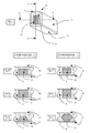
- Fig. 1 is a perspective view of an embodiment of an ear cup including a cushion according to the present invention;
- Fig. 2 is a cross-sectional view along the line A-A in Fig. 1;
- Fig. 3 is a sectional perspective view of part of an interface member according to an embodiment of the present invention;
- Fig. 4 is a cross-sectional view along the line X-X in Fig. 3;
- Fig. 5 is an alternative possibility for the cross-sectional view X-X in a different embodiment of an interface member according to the present invention;
- Fig. 6 is a further alternative possibility for the cross-sectional view X-X in a different embodiment of an interface member according to the present invention;
- Fig. 7 is a cross-sectional view along the line Z-Z in Fig. 3;
- Fig. 8 is an alternative possibility for the cross-sectional view Z-Z in a different embodiment of an interface member according to the present invention;
- Fig. 9 is a further alternative possibility for the cross-sectional view Z-Z in a different embodiment of an interface member according to the present invention.
- Fig.10 is an exploded sectional perspective view showing a construction of independent materials.
-
- Figs. 1 and 2 will be described with reference to an embodiment of the present invention which is an ear cup including a cushion (e.g. for an acoustic noise attenuating headset, ear defenders or headphones etc) but the concept may equally be applied to interface members for other types of apparatus as explained above, for example face masks or goggles or close fitting helmets etc. Similarly, Figs. 3 - 9 show some possible configurations of such interface members and those configurations may be substituted in the ear cushion of Fig. 1 as well as being suitable for use in the other types of apparatus envisaged in this application.
- In Fig.1, the ear cushion may include a substrate or
backing plate 2 on which is mounted a cushioning member 4 (referred to above generally as interface means). In this case, the cushioning member is generally rectangular in cross-section (preferably with radiused corners) and oval in shape so as to conform to the perimeter of thesubstrate 2. Anupper surface 6 of the cushioning member is intended to lie adjacent the head of the wearer in use. - The
cushioning member 4 includes two regions of material, thefirst region 8 has a first compliance A and thesecond region 10 has a second compliance B, where compliance B is less than compliance A. In fact, in this example theregion 10 is split into twoparts part 12 is intended to lie adjacent the skull bone behind the upper area of a wearer's ear andpart 14 is intended to lie adjacent the temporal process. - The aim of this embodiment of the present invention is to provide material of relatively high comfort (i.e. relatively high compliance or low density) adjacent or against those areas of the wearer's ear region (pinna) which are sensitive (such as the temple area and the area at the base of the ear), so the apparatus is comfortable to wear. In addition, areas of relatively low compliance (i.e. high stiffness or density) are provided so as to lie adjacent or press against relatively less sensitive areas of the wearer's ear region. This enables the cushion as a whole to provide a relatively more comfortable seal and, in the case of a hearing protector, better acoustic attenuation where it is useful.
- Where the level of acoustic attenuation is significant, the attenuation is a function of the stiffness K of any given material (e.g. ear cushion material). Stiffness K is the inverse of the compliance C of a material i.e. C = 1/K. In the above example, the stiffness of the
second region 10 of material dominates the system under load (i.e. in use) and therefore the attenuation provided by the apparatus is largely determined by thestiffer region 10, whilst still providing levels of comfort according toregion 8. - Fig. 2 is a cross-sectional view along the line A-A of Fig. 1 through
region 14.Region 12 may have a similar cross-sectional view or alternatively may be different. Cross-sectional views of alternative embodiments could be as shown in any of Figs. 4 - 9, for example. - In Fig. 2 it can be seen that effectively a section of
material 8 has either been removed or not manufactured in the first place and in its place is located theregion 10 of the second material (Ref Fig. 10). Theupper surface 6 of the ear cushion is intended to press against the wearer's head in use and, as can be seen, bothregions - However, as shown in Figs. 3 - 9, the upper surface of the cushion may also include a skin or cover which may be applied separately or fabricated as part of the materials for
regions 8 and/or 10. Furthermore, in the alternative embodiments illustrated by Figs. 4 and 6, it can be seen that theregion 10 does not directly contact the body of the wearer (or the cover or skin of the apparatus, where appropriate) but instead is itself wholly or partly covered by some of theregion 8. - Polyurethane Foam (possibly with a skin may be used as suitable cushion material.
- Fig. 3 shows a sectional view through part of a cushion or interface means according to an embodiment of the present invention. As stated above, such a cushion could be used as part of, for example, an ear defender according to Fig.1 or could be used as the cushioning member for many other types of apparatus as previously described.
- In Fig. 3, the cushioning member (generally 30) may sits on a base or
substrate 32. The cushioning member includes an optional cover orskin 34 which covers the cushioning material. As in the embodiment of Fig. 1, the cushioning material includes two regions and the same numbering will be used for clarity -region 8 is a first region of relatively high compliance material andregion 10 is a second region of relatively low compliance material. - In this example, the first region of
material 8 encloses the region ofmaterial 10 on all sides other than that which contacts thesubstrate 32. This is clear from the cross-sectional view shown in Figs. 4 and 7. However, alternative embodiments are possible and examples of these are shown in the cross-sectional view of Figs. 5,6,8 & 9. For example, theregion material 10 may extend from thesubstrate 32 to theupper surface 6, or only part of the way. Additionally or alternatively, theregion 10 may extend from one side of the cushion member to the other or only part of the way. - Fig. 10 shows an exploded view of a cushion member similar to that of Fig. 3. In Fig. 10, the cushion member is constructed in two parts - a region of
material 10 is inserted into an appropriate space in the first region ofmaterial 8. - In this and other embodiments (including the embodiment of Fig. 1) the substrate need not be an independent item but instead could simply be a portion of the apparatus to which the cushioning member is attached e.g. the ear cup in the embodiment of Fig. 1.
- The above embodiments are intended to be an example of the present invention and variants and modifications of those embodiments, such as would be readily apparent to the skilled person, are envisaged and may be made without departing from the scope of the present invention. For example, the above embodiments have been described with reference only to two regions of material of respectively different compliances, but it is possible to include further regions of material having other compliance levels as appropriate for the particular article to which the cushion is applied.
Claims (10)
- Apparatus for covering some or all of a wearer's body, including interface means which in use are adjacent the wearer's body, the interface means including a first region of material having a first compliance and a second region of material having a second compliance, the first compliance being greater than the second compliance, wherein both of the regions are adjacent respective parts of the wearer's body.
- Apparatus according to Claim 1 wherein the part of the wearer's body on which the apparatus is worn is the head, the face region, the eye region, the ear region or the cranial region.
- Apparatus according to Claim 1 or Claim 2 wherein it is arranged so that in use the first region is adjacent sensitive areas of the wearer's body and the second region located adjacent less sensitive areas.
- Apparatus according to any claim wherein the apparatus has an area, designed or shaped to fit the relevant part of the wearer's body and the interface means is attached to this area so that, the interface means contacts the relevant part of the wearer's body in use.
- Apparatus according to Claim 4 wherein the interface means covers the whole of the area and the second region of the interface means does not cover the whole area or perimeter but only a part of it.
- Apparatus according to Claim 5 wherein the interface means covers the whole area or alternatively covers the whole area.
- Apparatus according to Claim 5 or Claim 6 wherein the first region wholly or partly encloses the second region.
- Apparatus according to any of the above claims wherein either or both of the regions is covered with a suitable protective material.
- Apparatus according to any of the above claims wherein the apparatus is an ear cup to be worn over the ear of a wearer, and arranged such that in use the first region lies adjacent the temple of the wearer and the second region lies adjacent the top of the ear of the wearer.
- A method of constructing apparatus for covering all or a part of a wearer's body, the apparatus including interface means which in use are adjacent the wearer's body, the method including providing a first region of material of a first compliance and the second region of material of a second compliance, the first compliance being greater than the second compliance wherein both regions are adjacent respective parts of the wearer's body in use.
Applications Claiming Priority (2)
| Application Number | Priority Date | Filing Date | Title |
|---|---|---|---|
| GB0223894A GB2394166B (en) | 2002-10-14 | 2002-10-14 | Cushions |
| GB0223894 | 2002-10-14 |
Publications (1)
| Publication Number | Publication Date |
|---|---|
| EP1417944A1 true EP1417944A1 (en) | 2004-05-12 |
Family
ID=9945897
Family Applications (1)
| Application Number | Title | Priority Date | Filing Date |
|---|---|---|---|
| EP03103738A Withdrawn EP1417944A1 (en) | 2002-10-14 | 2003-10-09 | Cushions for covering a wearer's body |
Country Status (3)
| Country | Link |
|---|---|
| US (1) | US20050273910A1 (en) |
| EP (1) | EP1417944A1 (en) |
| GB (1) | GB2394166B (en) |
Cited By (2)
| Publication number | Priority date | Publication date | Assignee | Title |
|---|---|---|---|---|
| WO2010062944A1 (en) | 2008-11-26 | 2010-06-03 | Bose Corporation | High transmission loss headphone cushion |
| US8467539B2 (en) | 2008-11-26 | 2013-06-18 | Bose Corporation | High transmission loss cushion |
Families Citing this family (32)
| Publication number | Priority date | Publication date | Assignee | Title |
|---|---|---|---|---|
| US20070000025A1 (en) * | 2001-08-07 | 2007-01-04 | Brooke Picotte | Head protector for infants, small children, senior citizens, adults or physically disabled individuals |
| GB2431859A (en) * | 2005-10-31 | 2007-05-09 | Lloyd | A body protecting device comprising an array of energy absorbing cells |
| GB0609919D0 (en) | 2006-05-18 | 2006-06-28 | Speedo Int Ltd | Goggles |
| JP5082764B2 (en) * | 2007-10-25 | 2012-11-28 | ソニー株式会社 | Earpad and headphone device |
| US7717226B2 (en) * | 2008-02-20 | 2010-05-18 | Kimberly-Clark Worldwide, Inc. | Hearing protection cap |
| US20100119076A1 (en) * | 2008-11-12 | 2010-05-13 | The Timao Group, Inc. | Hearing Protection Device Ear Seal With Acoustic Barrier |
| DE202008016854U1 (en) * | 2008-12-22 | 2010-02-25 | Sennheiser Electronic Gmbh & Co. Kg | Earpiece, headset and earpads |
| US20120102629A1 (en) * | 2010-08-09 | 2012-05-03 | Spear Labs, Llc | Hearing protection system for use within a helmet |
| EP2763638B1 (en) | 2011-10-07 | 2019-02-20 | Hearing Components, Inc. | Foam cushion for headphones |
| US10088936B2 (en) * | 2013-01-07 | 2018-10-02 | Novasentis, Inc. | Thin profile user interface device and method providing localized haptic response |
| CN103108267A (en) * | 2013-01-16 | 2013-05-15 | 歌尔声学股份有限公司 | Composite-structure ear cap |
| US9479855B2 (en) * | 2014-11-20 | 2016-10-25 | Merry Electronics (Shenzhen) Co., Ltd. | Headphone ear cup |
| US10080077B2 (en) | 2016-02-09 | 2018-09-18 | Bose Corporation | Ear cushion for headphone |
| USD794603S1 (en) * | 2016-02-23 | 2017-08-15 | Ossic Corporation | Earphone |
| JP6744203B2 (en) * | 2016-12-14 | 2020-08-19 | 株式会社ジャパンディスプレイ | Display device |
| USD817304S1 (en) * | 2017-02-23 | 2018-05-08 | Muzik Inc. | Over ear fuzzy ear cushions and on ear fuzzy ear cushions for audio headphones |
| USD846526S1 (en) * | 2017-03-03 | 2019-04-23 | Shaun Jerrell Spencer | Headphone cover |
| USD868025S1 (en) * | 2018-03-22 | 2019-11-26 | Neal John Brace | Pair of ear pads |
| USD985936S1 (en) * | 2019-11-17 | 2023-05-16 | KiflePods Corporation | Pair of protective covers for headphones |
| CN112887859A (en) * | 2019-11-30 | 2021-06-01 | 华为技术有限公司 | Ear pad, ear muff part and earphone |
| WO2022073735A1 (en) | 2020-10-09 | 2022-04-14 | Gn Audio A/S | On-the-ear ear cushion with multiple foams having different properties |
| USD1021851S1 (en) * | 2020-12-17 | 2024-04-09 | Nickolai Vysokov | Headset earpad |
| USD1021850S1 (en) * | 2020-12-17 | 2024-04-09 | Nickolai Vysokov | Headset earpad |
| USD987599S1 (en) * | 2021-04-06 | 2023-05-30 | Amzaleg's LLC | Ear phone cover |
| GB202108903D0 (en) * | 2021-06-21 | 2021-08-04 | Daigneault Etienne | Impact protecting cap for use under helmet |
| DE102021133734A1 (en) | 2021-12-17 | 2023-06-22 | beyerdynamic GmbH & Co.KG | Pads for headphones |
| JP1742705S (en) * | 2022-09-14 | 2023-04-24 | headphone | |
| JP1742704S (en) * | 2022-09-14 | 2023-04-24 | headphone | |
| USD1000414S1 (en) * | 2023-05-18 | 2023-10-03 | Song WAN | Ear pad |
| USD1066285S1 (en) * | 2023-08-11 | 2025-03-11 | Amzaleg's, LLC | Earphone cover |
| USD1082741S1 (en) * | 2023-08-29 | 2025-07-08 | Daniel D. Willman | Pair of headphone headset covers with guide passthroughs |
| USD1081619S1 (en) * | 2025-01-21 | 2025-07-01 | Zaihua Cheng | Pair of headphone ear pad covers |
Citations (7)
| Publication number | Priority date | Publication date | Assignee | Title |
|---|---|---|---|---|
| US1873864A (en) * | 1929-02-01 | 1932-08-23 | Hiram B Ely | Ear mask |
| FR2360299A1 (en) * | 1976-08-06 | 1978-03-03 | Socapex | SEALING CUSHION FOR ACOUSTIC PROTECTION DEVICE OF THE HEARING SYSTEM, AND PROTECTION DEVICE CONTAINING SUCH CUSHIONS |
| US4155180A (en) * | 1975-12-29 | 1979-05-22 | American Fitness, Inc. | Footwear for more efficient running |
| US5086789A (en) * | 1989-09-13 | 1992-02-11 | Tichy James B | Wind deflector for the ear |
| EP0776616A2 (en) * | 1995-11-30 | 1997-06-04 | Uni-Charm Corporation | Disposable sanitary mask |
| US6152137A (en) * | 1995-01-23 | 2000-11-28 | Schwartz; Alan N. | Pliable and resilient sealing pad |
| WO2001043804A1 (en) * | 1999-12-16 | 2001-06-21 | Compumedics Sleep Pty. Ltd. | Bio-mask with integral sensors |
Family Cites Families (24)
| Publication number | Priority date | Publication date | Assignee | Title |
|---|---|---|---|---|
| US1333012A (en) * | 1920-03-09 | de puydt and h | ||
| US3506980A (en) * | 1968-12-26 | 1970-04-21 | Gentex Corp | Seal for earcup or the like |
| US3593341A (en) * | 1970-01-02 | 1971-07-20 | Gentex Corp | Sound-attenuating earcups |
| US3875592A (en) * | 1973-01-10 | 1975-04-08 | Gentex Corp | Sound attenuating earcup |
| US3984885A (en) * | 1974-03-15 | 1976-10-12 | Matsushita Electric Industrial Co., Ltd. | 4-Channel headphones |
| US3944018A (en) * | 1974-08-01 | 1976-03-16 | Rodney Jene Satory | Acoustical seal |
| FR2595498B1 (en) * | 1986-03-07 | 1989-06-02 | Centre Nat Rech Scient | METHODS AND DEVICES FOR MITIGATING EXTERNAL NOISE ARISING AT TYMPAN AND IMPROVING THE INTELLIGIBILITY OF ELECTROACOUSTIC COMMUNICATIONS |
| US4723322A (en) * | 1987-03-16 | 1988-02-09 | Spenco Medical Corporation | Knee pad |
| US4922542A (en) * | 1987-12-28 | 1990-05-01 | Roman Sapiejewski | Headphone comfort |
| US4905322A (en) * | 1988-04-18 | 1990-03-06 | Gentex Corporation | Energy-absorbing earcup assembly |
| US5020163A (en) * | 1989-06-29 | 1991-06-04 | Gentex Corporation | Earseal for sound-attenuating earcup assembly |
| US5305387A (en) * | 1989-10-27 | 1994-04-19 | Bose Corporation | Earphoning |
| US5309576A (en) * | 1991-06-19 | 1994-05-10 | Bell Helmets Inc. | Multiple density helmet body compositions to strengthen helmet |
| US5138722A (en) * | 1991-07-02 | 1992-08-18 | David Clark Company Inc. | Headset ear seal |
| US5500958A (en) * | 1994-01-19 | 1996-03-26 | Cabot Safety Corporation | Seal plate attachment for earmuffs |
| US5400296A (en) * | 1994-01-25 | 1995-03-21 | Poiesis Research, Inc. | Acoustic attenuation and vibration damping materials |
| US5756195A (en) * | 1995-06-07 | 1998-05-26 | Acushnet Company | Gel cushion conprising rubber polymer and oil |
| JPH08277340A (en) * | 1995-04-05 | 1996-10-22 | Jsp Corp | Polypropylene homopolymer expanded particles and expanded particle molded products |
| EP0779763A1 (en) * | 1995-12-13 | 1997-06-18 | Augusto Salzani | Improved headphone including split earphones and coupling means for coupling it to the ears |
| US5920911A (en) * | 1997-11-17 | 1999-07-13 | Poiesis Research, Inc. | Earcup soft-seal with thinned lips and interleaving layers of damping materials |
| US5950244A (en) * | 1998-01-23 | 1999-09-14 | Sport Maska Inc. | Protective device for impact management |
| US5911314A (en) * | 1998-03-31 | 1999-06-15 | David Clark Company Inc. | Headset ear seal |
| SE514555C2 (en) * | 1999-07-08 | 2001-03-12 | Peltor Ab | Method of making cover and cover made according to the procedure |
| US6467483B1 (en) * | 1999-07-28 | 2002-10-22 | Respironics, Inc. | Respiratory mask |
-
2002
- 2002-10-14 GB GB0223894A patent/GB2394166B/en not_active Expired - Lifetime
-
2003
- 2003-10-07 US US10/679,698 patent/US20050273910A1/en not_active Abandoned
- 2003-10-09 EP EP03103738A patent/EP1417944A1/en not_active Withdrawn
Patent Citations (7)
| Publication number | Priority date | Publication date | Assignee | Title |
|---|---|---|---|---|
| US1873864A (en) * | 1929-02-01 | 1932-08-23 | Hiram B Ely | Ear mask |
| US4155180A (en) * | 1975-12-29 | 1979-05-22 | American Fitness, Inc. | Footwear for more efficient running |
| FR2360299A1 (en) * | 1976-08-06 | 1978-03-03 | Socapex | SEALING CUSHION FOR ACOUSTIC PROTECTION DEVICE OF THE HEARING SYSTEM, AND PROTECTION DEVICE CONTAINING SUCH CUSHIONS |
| US5086789A (en) * | 1989-09-13 | 1992-02-11 | Tichy James B | Wind deflector for the ear |
| US6152137A (en) * | 1995-01-23 | 2000-11-28 | Schwartz; Alan N. | Pliable and resilient sealing pad |
| EP0776616A2 (en) * | 1995-11-30 | 1997-06-04 | Uni-Charm Corporation | Disposable sanitary mask |
| WO2001043804A1 (en) * | 1999-12-16 | 2001-06-21 | Compumedics Sleep Pty. Ltd. | Bio-mask with integral sensors |
Cited By (5)
| Publication number | Priority date | Publication date | Assignee | Title |
|---|---|---|---|---|
| WO2010062944A1 (en) | 2008-11-26 | 2010-06-03 | Bose Corporation | High transmission loss headphone cushion |
| US8374373B2 (en) | 2008-11-26 | 2013-02-12 | Bose Corporation | High transmission loss headphone cushion |
| AU2009319813B2 (en) * | 2008-11-26 | 2013-04-18 | Bose Corporation | High transmission loss headphone cushion |
| US8467539B2 (en) | 2008-11-26 | 2013-06-18 | Bose Corporation | High transmission loss cushion |
| CN102224742B (en) * | 2008-11-26 | 2014-08-06 | 伯斯有限公司 | High transmission loss headphone cushion |
Also Published As
| Publication number | Publication date |
|---|---|
| GB2394166A (en) | 2004-04-21 |
| US20050273910A1 (en) | 2005-12-15 |
| GB0223894D0 (en) | 2002-11-20 |
| GB2394166B (en) | 2006-01-18 |
Similar Documents
| Publication | Publication Date | Title |
|---|---|---|
| US20050273910A1 (en) | Cushions | |
| US8638969B2 (en) | Earphone, headset and ear pad | |
| US6163615A (en) | Circumaural ear cup audio seal for use in connection with a headset, ear defender, helmet and the like | |
| US10841686B2 (en) | Accommodating ear pads | |
| US4674134A (en) | Earmuff having sealing ring including liquid and foam plastic layers | |
| KR101619554B1 (en) | Bandless hearing protector and method | |
| US4958697A (en) | Anatomically shaped earseals for headsets | |
| ES2206556T3 (en) | HEADPHONE PROTECTOR. | |
| US20050125882A1 (en) | Padset for protective helmet | |
| US20160354252A9 (en) | Sound muffling headwear | |
| JP2017512540A (en) | Earplug and earplug set having the same | |
| KR101105520B1 (en) | ear plug | |
| EP3188494A1 (en) | A headphone with two ear cushions of different hardness | |
| JP2011160310A (en) | Headphone | |
| WO2022047045A1 (en) | Headphone adapted to provide improved performance and comfort for eyeglass wearers | |
| EP3614983B1 (en) | A device wearable on the head of a user | |
| JP5131096B2 (en) | headphone | |
| EP2329736A1 (en) | Helmet Configuration. | |
| US20040237171A1 (en) | Disposable protective device | |
| TWI754134B (en) | Headphone | |
| US20230139105A1 (en) | Circumaural ear cushion/seal | |
| US20190215593A1 (en) | Highly-Closed Headphone Apparatus with Wearing Comfort | |
| US20130329933A1 (en) | Hexagonal Headphone Earpiece | |
| US6684976B1 (en) | Headset ear seal | |
| FI58054C (en) | HOERSELSKYDD FOER ANVAENDNING TILLSAMMANS MED GLASOEGONSKALMAR |
Legal Events
| Date | Code | Title | Description |
|---|---|---|---|
| PUAI | Public reference made under article 153(3) epc to a published international application that has entered the european phase |
Free format text: ORIGINAL CODE: 0009012 |
|
| AK | Designated contracting states |
Kind code of ref document: A1 Designated state(s): AT BE BG CH CY CZ DE DK EE ES FI FR GB GR HU IE IT LI LU MC NL PT RO SE SI SK TR |
|
| AX | Request for extension of the european patent |
Extension state: AL LT LV MK |
|
| 17P | Request for examination filed |
Effective date: 20041027 |
|
| RAP1 | Party data changed (applicant data changed or rights of an application transferred) |
Owner name: RACAL ACOUSTICS LIMITED |
|
| AKX | Designation fees paid |
Designated state(s): AT BE BG CH CY CZ DE DK EE ES FI FR GB GR HU IE IT LI LU MC NL PT RO SE SI SK TR |
|
| 17Q | First examination report despatched |
Effective date: 20070720 |
|
| STAA | Information on the status of an ep patent application or granted ep patent |
Free format text: STATUS: THE APPLICATION IS DEEMED TO BE WITHDRAWN |
|
| 18D | Application deemed to be withdrawn |
Effective date: 20080131 |