EP1417053B1 - Workpiece forming - Google Patents
Workpiece forming Download PDFInfo
- Publication number
- EP1417053B1 EP1417053B1 EP02753137A EP02753137A EP1417053B1 EP 1417053 B1 EP1417053 B1 EP 1417053B1 EP 02753137 A EP02753137 A EP 02753137A EP 02753137 A EP02753137 A EP 02753137A EP 1417053 B1 EP1417053 B1 EP 1417053B1
- Authority
- EP
- European Patent Office
- Prior art keywords
- workpiece
- mould
- laser
- sheets
- pillars
- Prior art date
- Legal status (The legal status is an assumption and is not a legal conclusion. Google has not performed a legal analysis and makes no representation as to the accuracy of the status listed.)
- Expired - Lifetime
Links
- 238000000034 method Methods 0.000 claims abstract description 34
- 239000012530 fluid Substances 0.000 claims abstract description 17
- 238000010438 heat treatment Methods 0.000 claims description 8
- 238000007493 shaping process Methods 0.000 claims description 2
- 239000002826 coolant Substances 0.000 claims 2
- 239000000463 material Substances 0.000 abstract description 7
- 239000007789 gas Substances 0.000 description 8
- 239000000956 alloy Substances 0.000 description 7
- 229910045601 alloy Inorganic materials 0.000 description 6
- XKRFYHLGVUSROY-UHFFFAOYSA-N Argon Chemical compound [Ar] XKRFYHLGVUSROY-UHFFFAOYSA-N 0.000 description 4
- 229910010293 ceramic material Inorganic materials 0.000 description 3
- 238000009792 diffusion process Methods 0.000 description 3
- 238000000137 annealing Methods 0.000 description 2
- 229910052786 argon Inorganic materials 0.000 description 2
- 239000011261 inert gas Substances 0.000 description 2
- RTAQQCXQSZGOHL-UHFFFAOYSA-N Titanium Chemical compound [Ti] RTAQQCXQSZGOHL-UHFFFAOYSA-N 0.000 description 1
- 230000006978 adaptation Effects 0.000 description 1
- 230000015572 biosynthetic process Effects 0.000 description 1
- 239000000919 ceramic Substances 0.000 description 1
- 238000007796 conventional method Methods 0.000 description 1
- 239000000112 cooling gas Substances 0.000 description 1
- 229910002106 crystalline ceramic Inorganic materials 0.000 description 1
- 239000011222 crystalline ceramic Substances 0.000 description 1
- 230000000694 effects Effects 0.000 description 1
- 239000012467 final product Substances 0.000 description 1
- 238000004093 laser heating Methods 0.000 description 1
- 238000004519 manufacturing process Methods 0.000 description 1
- 230000003287 optical effect Effects 0.000 description 1
- 230000005855 radiation Effects 0.000 description 1
- 229910052719 titanium Inorganic materials 0.000 description 1
- 239000010936 titanium Substances 0.000 description 1
Images



Classifications
-
- B—PERFORMING OPERATIONS; TRANSPORTING
- B21—MECHANICAL METAL-WORKING WITHOUT ESSENTIALLY REMOVING MATERIAL; PUNCHING METAL
- B21D—WORKING OR PROCESSING OF SHEET METAL OR METAL TUBES, RODS OR PROFILES WITHOUT ESSENTIALLY REMOVING MATERIAL; PUNCHING METAL
- B21D26/00—Shaping without cutting otherwise than using rigid devices or tools or yieldable or resilient pads, i.e. applying fluid pressure or magnetic forces
- B21D26/02—Shaping without cutting otherwise than using rigid devices or tools or yieldable or resilient pads, i.e. applying fluid pressure or magnetic forces by applying fluid pressure
- B21D26/053—Shaping without cutting otherwise than using rigid devices or tools or yieldable or resilient pads, i.e. applying fluid pressure or magnetic forces by applying fluid pressure characterised by the material of the blanks
- B21D26/055—Blanks having super-plastic properties
Definitions
- This invention relates to a method of shaping a workpiece, and in particular to a method of superplastic forming of a suitable material.
- One method of forming a workpiece is to place a sheet of the alloy material over a die, or mould, and then to heat the workpiece to a temperature at which the alloy becomes superplastic, and then to apply pressure to the workpiece, for example by applying a high fluid pressure to the upper surface of the workpiece while maintaining a lower pressure in the region between the workpiece and the die.
- the workpiece then takes the shape of the inner surface of the die.
- US Patent No. 5,592,842 discloses a method which seeks to avoid the requirement for a mould. Specifically, this document proposes using a laser beam to locally heat parts of the workpiece, and then applying fluid pressure as in the conventional method.
- the disclosed method makes no provision for annealing the workpiece, without which subsequent forming would not be satisfactory, or for heating the workpiece after forming, thereby eliminating residual stresses that may be produced by the forming process.
- a method of forming a workpiece comprising:
- the workpiece is clamped, and the laser is used to heat the whole of the workpiece to a substantially uniform temperature to anneal it.
- the laser is used to heat the whole of the workpiece to a substantially uniform temperature to remove any residual stresses.
- a forming apparatus comprising:
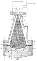
- FIG. 1 is a schematic cross-sectional view through the forming apparatus according to an aspect of the present invention.
- the apparatus includes a pressure vessel 10, having a viewing inlet 12.
- the vessel 10 includes a clamping system 14, 16, which can apply a clamping force as shown by arrows A-A, B-B, to hold a workpiece 18 in place.
- the workpiece 18 is a sheet of the required superplastic alloy.
- the superplastic alloy may for example be a titanium-based alloy.
- the workpiece 18 is preferably provided originally flat.
- Figure 1 shows the workpiece having been partially deformed.
- the apparatus includes a mould 20, located inside an insulating ring 22 made of a ceramic material.
- the upper surface 24 of the mould 20 conforms to the desired shape of the component after forming, and the mould 20 further includes bleed passages 26, 28.
- the mould 20 may be made from either metallic or ceramic materials.
- the apparatus also includes a laser light source 30, including means for controlling the focussing and direction of the laser beam 32.
- the pressure vessel 10 also includes inlets 34 for gas, as well as an outlet 36.
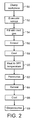
- FIG 2 is a flowchart showing a forming process, in accordance with a preferred aspect of the invention, using the apparatus shown in Figure 1.
- the workpiece preferably in the form of a generally flat sheet of a superplastic material
- the vessel is evacuated by a vacuum pump, for example through the outlets 26, 28, 34, 36.
- the vessel is refilled with an inert gas, such as argon, at low pressure. This inert environment allows the component to be heated, without becoming contaminated with atmospheric gases.
- the laser light source 30 is used to heat the whole of the workpiece 18, to a sufficiently high temperature that it is fully annealed and stress free. As shown in Figure 3, the whole of the workpiece 18 is heated substantially uniformly. This is achieved by suitable control of the laser light source 30.
- the laser light beam can be defocussed, so that it reaches all parts of the workpiece 18, or a focussed light beam can be scanned over all regions of the surface.
- step 58 the workpiece is allowed to cool to below the superplastic temperature or, if possible, to below the grain-growth temperature.
- the laser light source 30 is used to heat the workpiece 18 to its superplastic forming (SPF) temperature, for example at 935°C.
- SPF superplastic forming
- different regions of the workpiece 18 may be supplied with different amounts of energy from the laser light source 30.
- bands 80. 82, 84 are shown in Figure 4, and they may receive different energy levels. Controlling the amount of energy supplied in this way allows superplasticity to be induced preferentially in some parts of the workpiece, rather than in others.
- step 62 of the process the vessel is pressurised. That is, inert gas, such as argon, is introduced through the gas inlets 34, in order to increase the pressure on the upper surface of the workpiece 18. At the same time, gas is allowed to escape from the underside of the workpiece 18 through the gas outlet channels 26, 28.
- the gas pressure on the upper side of the workpiece 18, within the vessel 10 may be increased to about 30 or 40 atmospheres (3MPa or 4MPa).
- This pressure forces the hot workpiece into the mould 20, thereby forming a component having the same profile as the inner surface 24 of the mould.
- the laser source 30 can be used to reheat the formed component (step 64 in Figure 2).
- the distribution profile of the heat energy from the laser source may need to vary, for example between bands 92, 94, for example because of the now non-planar shape of the workpiece 18. Heating the component in this way eliminates any residual stresses within the component, that may have been induced as a result of the forming process, in order to produce components of superior accuracy and reproducibility without spring-back.
- the component can then be allowed to cool (step 66 in Figure 2), and finally, in step 68 of the process shown in Figure 2, the vessel can be depressurised.
- Figure 6 shows an alternative forming apparatus in accordance with an aspect of the present invention.
- the forming apparatus of Figure 6 is adapted for use in forming components made of two sheets of material.
- the apparatus includes a second laser light source (not shown) which is at an opposite end of the apparatus.
- the pressure vessel includes means for retaining two mould halves 100, 102, and for clamping two workpiece sheets 104, 106, whose edges may have been fused together, with an inlet 108, for introducing high pressure gas in between the two workpiece sheets 104, 106.
- the laser light sources can be used to heat the mould halves 100, 102, and thereby raise the temperature of the workpiece sheets 104, 106 to their SPF temperature.
- the mould halves 100, 102 can be made from a material which is transparent to laser light, thereby allowing the laser light source to penetrate the mould halves, and heat the workpiece sheets directly.
- Suitable mould materials for this purpose can be either amorphous or crystalline ceramic, for example by ensuring that the grain size of the ceramic is smaller than the wavelength of the laser.
- the mould halves 100, 102 may be designed for repeated use, or may be made in the form of a disposable liner.
- the forming process in the case of the apparatus shown in Figure 6, is generally similar to that described with reference to Figure 2, although in this case the high pressure gas is introduced between the two workpiece sheets 104, 106, in order to force the sheets into the respective mould halves 100, 102. In that case, the required high pressure is contained within the workpiece, and is of considerably smaller volume than in the situation shown in Figure 1.
- Figure 7 is a schematic illustration of a further forming apparatus in accordance with an aspect of the invention.
- the apparatus of Figure 7 is generally similar to that of Figure 1, and the same reference numerals, when used in the two Figures, indicate corresponding features, and these features will not be described further.
- the mould 120 is formed from an array comprising a large number of individually movable pillars 122, under the control of a servo system 124. Although only a few pillars 122 are shown in Figure 7, an operational apparatus may include hundreds or thousands of such pillars.
- Each pillar has a tip 126 which is made of, or coated with, a ceramic material.
- the servo system 124 can control the height of each of the pillars 122, and can preferably also control the lateral positions of the pillars to a small extent. In this way, the array of pillars 122 can be used to form a mould of any desired shape. After use, the positions of the pillars can be adjusted to form a mould of a different desired shape. This allows many different components to be formed without requiring a corresponding number of different moulds.
- the forming process is the same as that described earlier, in that the workpiece is clamped over the mould, then heated to its SPF temperature, and then a pressure is applied so that the workpiece takes the shape of the mould.
- a mould of this type can also be used in an apparatus for forming components made from two sheets, as shown in Figure 6.
- a mould of this type can be used in many different forming processes, not only those involving laser heating of workpieces, or superplasticity.
- an adjustable mould comprising a plurality of individually adjustable pillars, and means for controlling the heights of the pillars, such that together the distal ends of the pillars form a mould surface.
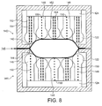
- Figure 8 shows a further adaptation of a mould of this type, in this case in an apparatus for forming components made from two sheets.
- the mould of Figure 8 is generally similar to that of Figure 7, and the same reference numerals, when used in the two Figures, indicate corresponding features, and these features will not be described further.
- the apparatus includes two moulds 140, 141 which are generally similar to the mould 120 of Figure 7, together with an arrangement for clamping two workpiece sheets 142, 144, and an inlet 146 for introducing high pressure fluid in between them.
- a first group of the pillars 148 each house respective optical fibres 150, which can direct radiation from the laser source (not shown), onto the adjacent area of the respective workpiece.
- a second group of pillars 152 each house respective channels 154, which can direct cooling gas flows onto the adjacent area of the respective workpiece.
- the pillars 148, 152 of the first and second groups are generally alternated over the respective mould surfaces.
- the apparatus of Figure 8 allows precise control of the surface temperature of the workpiece, allowing superplasticity to be induced only in parts of the surface, if required.
- superplastic forming using two workpiece sheets, can be used to form components with an internal, diffusion bonded, webbed support structure.
- Figures 9-11 show such a process in accordance with the present invention.
- the laser light source is used to pretreat the outer surfaces 160, 162 of the two workpiece sheets 164, 166 respectively.
- the laser light source is able to form a controllable beam, it can be used to scan across the surfaces 160, 162, as shown for example by the path 168 in Figure 9. This removes any oxide which is present on the surfaces 160, 162, and the vaporised oxide can be vented out of the pressure vessel.
- the two workpiece sheets 164, 166 are diffusion bonded together along lines 170. Then, when the two workpiece sheets 164, 166 have been heated to their SPF temperature, and high pressure fluid is introduced through inlet 172 between them, the two workpiece sheets are forced apart, as shown in Figure 10.
Landscapes
- Physics & Mathematics (AREA)
- Fluid Mechanics (AREA)
- Engineering & Computer Science (AREA)
- Mechanical Engineering (AREA)
- Shaping Metal By Deep-Drawing, Or The Like (AREA)
- Grinding Of Cylindrical And Plane Surfaces (AREA)
- Laser Beam Processing (AREA)
- Moulds For Moulding Plastics Or The Like (AREA)
- Magnetic Heads (AREA)
- Materials For Medical Uses (AREA)
- Piezo-Electric Or Mechanical Vibrators, Or Delay Or Filter Circuits (AREA)
Abstract
Description
- This invention relates to a method of shaping a workpiece, and in particular to a method of superplastic forming of a suitable material.
- It is known that certain alloys become superplastic at specific elevated temperatures. At these temperatures, the superplasticity usefully allows the alloy to be formed into a desired shape.
- One method of forming a workpiece (for example as disclosed in
US-A-5868023 ) is to place a sheet of the alloy material over a die, or mould, and then to heat the workpiece to a temperature at which the alloy becomes superplastic, and then to apply pressure to the workpiece, for example by applying a high fluid pressure to the upper surface of the workpiece while maintaining a lower pressure in the region between the workpiece and the die. The workpiece then takes the shape of the inner surface of the die. - However, this has the disadvantage that the system has a high thermal mass. That is, not only must the workpiece be heated to the temperature at which it becomes superplastic, but typically the whole processing chamber must also be heated to the same temperature. This obviously requires a large energy input in order to form the required piece.
-
US Patent No. 5,592,842 discloses a method which seeks to avoid the requirement for a mould. Specifically, this document proposes using a laser beam to locally heat parts of the workpiece, and then applying fluid pressure as in the conventional method. - However, this method has the disadvantage that this cannot accurately control the shape of the final product.
- Moreover, the disclosed method makes no provision for annealing the workpiece, without which subsequent forming would not be satisfactory, or for heating the workpiece after forming, thereby eliminating residual stresses that may be produced by the forming process.
- According to a first aspect of the present invention, there is provided a method of forming a workpiece, comprising:
- holding the workpiece adjacent a mould;
- heating at least a part of the workpiece to a temperature sufficient to induce superplasticity therein; and
- applying a fluid pressure to the workpiece so that it takes the shape of the mould,
- This has the advantage that the superplastic properties of the material can be used to form the workpiece precisely to the required shape, without needing to heat all of the processing chamber to the superplastic temperature.
- Preferably, before using the laser to heat the workpiece to its superplastic temperature, the workpiece is clamped, and the laser is used to heat the whole of the workpiece to a substantially uniform temperature to anneal it.
- Also preferably, after using the laser to superplastically form the workpiece, the laser is used to heat the whole of the workpiece to a substantially uniform temperature to remove any residual stresses.
- This has the advantage that the whole of the forming can be carried out as a single process, in a single processing apparatus.
- According to a second aspect of the present invention, there is provided a forming apparatus, comprising:
- means for retaining a mould;
- means for clamping a workpiece adjacent the mould; and
- means for applying a fluid pressure to the workpiece so that it takes the shape of the mould, characterized in that
- a laser source is provided for heating at least a part of a workpiece held in the clamping means.
- For a better understanding of the present invention, and to show how it may be put into effect, reference will now be made, by way of example, to the accompanying drawings, in which:
- Figure 1 is a schematic cross-sectional view through a forming apparatus in accordance with an aspect of the invention.
- Figure 2 is a flowchart illustrating a process in accordance with an aspect of the invention.
- Figures 3-5 show the patterns of heating applied to a typical workpiece in accordance with the invention.
- Figure 6 is a schematic cross-sectional view through an alternative apparatus in accordance with the invention.
- Figure 7 is a schematic cross-sectional view through a further alternative apparatus in accordance with the invention.
- Figure 8 is a schematic representation of a further alternative apparatus in accordance with the invention.
- Figures 9-11 show stages in the process in accordance with an aspect of the invention.
- Figure 1 is a schematic cross-sectional view through the forming apparatus according to an aspect of the present invention. The apparatus includes a
pressure vessel 10, having aviewing inlet 12. Thevessel 10 includes aclamping system workpiece 18 in place. - The
workpiece 18 is a sheet of the required superplastic alloy. As is well known to the person skilled in the art, the superplastic alloy may for example be a titanium-based alloy. - The
workpiece 18 is preferably provided originally flat. Figure 1 shows the workpiece having been partially deformed. - The apparatus includes a
mould 20, located inside aninsulating ring 22 made of a ceramic material. Theupper surface 24 of themould 20 conforms to the desired shape of the component after forming, and themould 20 further includesbleed passages - The
mould 20 may be made from either metallic or ceramic materials. - The apparatus also includes a
laser light source 30, including means for controlling the focussing and direction of thelaser beam 32. - The
pressure vessel 10 also includesinlets 34 for gas, as well as anoutlet 36. - Figure 2 is a flowchart showing a forming process, in accordance with a preferred aspect of the invention, using the apparatus shown in Figure 1.
- Firstly, the workpiece, preferably in the form of a generally flat sheet of a superplastic material, is clamped in the
clamping system step 50 of the process. Then, instep 52, the vessel is evacuated by a vacuum pump, for example through theoutlets step 54, the vessel is refilled with an inert gas, such as argon, at low pressure. This inert environment allows the component to be heated, without becoming contaminated with atmospheric gases. - Next, in
step 56, thelaser light source 30 is used to heat the whole of theworkpiece 18, to a sufficiently high temperature that it is fully annealed and stress free. As shown in Figure 3, the whole of theworkpiece 18 is heated substantially uniformly. This is achieved by suitable control of thelaser light source 30. For example, the laser light beam can be defocussed, so that it reaches all parts of theworkpiece 18, or a focussed light beam can be scanned over all regions of the surface. - After annealing, in
step 58, the workpiece is allowed to cool to below the superplastic temperature or, if possible, to below the grain-growth temperature. - Then, in
step 60 of the process, thelaser light source 30 is used to heat theworkpiece 18 to its superplastic forming (SPF) temperature, for example at 935°C. In this case, as shown in Figure 4, different regions of theworkpiece 18 may be supplied with different amounts of energy from thelaser light source 30. Thus, for illustrative purposes only,bands 80. 82, 84 are shown in Figure 4, and they may receive different energy levels. Controlling the amount of energy supplied in this way allows superplasticity to be induced preferentially in some parts of the workpiece, rather than in others. - Next, in
step 62 of the process, the vessel is pressurised. That is, inert gas, such as argon, is introduced through thegas inlets 34, in order to increase the pressure on the upper surface of theworkpiece 18. At the same time, gas is allowed to escape from the underside of theworkpiece 18 through thegas outlet channels workpiece 18, within thevessel 10, may be increased to about 30 or 40 atmospheres (3MPa or 4MPa). - This pressure forces the hot workpiece into the
mould 20, thereby forming a component having the same profile as theinner surface 24 of the mould. - Once the component has been formed, the
laser source 30 can be used to reheat the formed component (step 64 in Figure 2). As shown in Figure 5, the distribution profile of the heat energy from the laser source may need to vary, for example betweenbands workpiece 18. Heating the component in this way eliminates any residual stresses within the component, that may have been induced as a result of the forming process, in order to produce components of superior accuracy and reproducibility without spring-back. The component can then be allowed to cool (step 66 in Figure 2), and finally, in step 68 of the process shown in Figure 2, the vessel can be depressurised. - Figure 6 shows an alternative forming apparatus in accordance with an aspect of the present invention. The forming apparatus of Figure 6 is adapted for use in forming components made of two sheets of material.
- The apparatus of Figure 6 is somewhat similar to that shown in Figure 1, and corresponding components are indicated by the same reference numerals, and will not be described further.
- In the case of the apparatus of Figure 6, the apparatus includes a second laser light source (not shown) which is at an opposite end of the apparatus. The pressure vessel includes means for retaining two
mould halves workpiece sheets inlet 108, for introducing high pressure gas in between the twoworkpiece sheets - In this case, the laser light sources can be used to heat the mould halves 100, 102, and thereby raise the temperature of the
workpiece sheets - The mould halves 100, 102 may be designed for repeated use, or may be made in the form of a disposable liner.
- The forming process, in the case of the apparatus shown in Figure 6, is generally similar to that described with reference to Figure 2, although in this case the high pressure gas is introduced between the two
workpiece sheets respective mould halves - Figure 7 is a schematic illustration of a further forming apparatus in accordance with an aspect of the invention. The apparatus of Figure 7 is generally similar to that of Figure 1, and the same reference numerals, when used in the two Figures, indicate corresponding features, and these features will not be described further.
- In the apparatus of Figure 7, the
mould 120 is formed from an array comprising a large number of individuallymovable pillars 122, under the control of aservo system 124. Although only afew pillars 122 are shown in Figure 7, an operational apparatus may include hundreds or thousands of such pillars. - Each pillar has a
tip 126 which is made of, or coated with, a ceramic material. - The
servo system 124 can control the height of each of thepillars 122, and can preferably also control the lateral positions of the pillars to a small extent. In this way, the array ofpillars 122 can be used to form a mould of any desired shape. After use, the positions of the pillars can be adjusted to form a mould of a different desired shape. This allows many different components to be formed without requiring a corresponding number of different moulds. - The forming process is the same as that described earlier, in that the workpiece is clamped over the mould, then heated to its SPF temperature, and then a pressure is applied so that the workpiece takes the shape of the mould.
- It will be appreciated that a mould of this type can also be used in an apparatus for forming components made from two sheets, as shown in Figure 6.
- It should further be noted that a mould of this type can be used in many different forming processes, not only those involving laser heating of workpieces, or superplasticity.
- Thus, according to one aspect of the invention, there is provided an adjustable mould, comprising a plurality of individually adjustable pillars, and means for controlling the heights of the pillars, such that together the distal ends of the pillars form a mould surface.
- Figure 8 shows a further adaptation of a mould of this type, in this case in an apparatus for forming components made from two sheets. The mould of Figure 8 is generally similar to that of Figure 7, and the same reference numerals, when used in the two Figures, indicate corresponding features, and these features will not be described further.
- In this case, the apparatus includes two
moulds mould 120 of Figure 7, together with an arrangement for clamping twoworkpiece sheets inlet 146 for introducing high pressure fluid in between them. - In the apparatus of Figure 8, a first group of the
pillars 148 each house respectiveoptical fibres 150, which can direct radiation from the laser source (not shown), onto the adjacent area of the respective workpiece. Further, a second group ofpillars 152 each houserespective channels 154, which can direct cooling gas flows onto the adjacent area of the respective workpiece. Thepillars - Thus, the apparatus of Figure 8 allows precise control of the surface temperature of the workpiece, allowing superplasticity to be induced only in parts of the surface, if required.
- As is known in the art, superplastic forming, using two workpiece sheets, can be used to form components with an internal, diffusion bonded, webbed support structure.
- Figures 9-11 show such a process in accordance with the present invention. Thus, as shown in Figure 9, the laser light source is used to pretreat the
outer surfaces workpiece sheets surfaces path 168 in Figure 9. This removes any oxide which is present on thesurfaces - As is known, the two
workpiece sheets lines 170. Then, when the twoworkpiece sheets inlet 172 between them, the two workpiece sheets are forced apart, as shown in Figure 10. - Eventually, as shown in Figure 11, regions of the
outer surfaces - The use of the laser in the pretreatment means that this can be carried out as a part of the forming process, using the same forming apparatus.
- There are therefore disclosed manufacturing methods which allow efficient use of superplastic forming.
Claims (18)
- A method of forming a workpiece (18), comprising:holding the workpiece (18) adjacent a mould (20);heating at least a part of the workpiece (18) to a temperature sufficient to induce superplasticity therein; andapplying a fluid pressure to the workpiece (18) so that it takes the shape of the mould (20),characterized in that a laser (30) is used to heat the workpiece (18).
- A method as claimed in claim 1, characterized in that the step of holding the workpiece (18) comprises:clamping the workpiece (18) adjacent the mould (20);using the laser (30) to heat the whole of the workpiece (18) to a substantially uniform temperature to anneal it; andreducing the temperature of the workpiece (18) to below the superplastic temperature thereof.
- A method as claimed in claim 1 or 2, characterized in that, after shaping the workpiece (18):the laser (30) is used to heat the whole of the workpiece (18) to a substantially uniform temperature to remove residual stresses therein.
- A method as claimed in any preceding claim, characterized in that the mould comprises first and second halves (100,102), and the workpiece comprises first and second sheets (104,106), the method comprising:holding the first and second sheets (104,106) of the workpiece adjacent the first and second halves (100,102) of the mould, respectively;using the laser (30) to heat at least parts of the first and second sheets (104,106) of the workpiece; andapplying fluid pressure to the first and second sheets (104,106) of the workpiece so that they take the respective shapes of the first and second halves of the mould.
- A method as claimed in claim 4, characterized in that the step of applying fluid pressure comprises applying an increased fluid pressure between the first and second sheets (104,106) of the workpiece.
- A method as claimed in claim 4 or 5, characterized in that at least one of the first and second halves (100,102) of the mould is transparent to the laser (30), and the step of using the laser (30) to heat at least parts of the first and second sheets (104,106) of the workpiece comprises heating at least one of the first and second sheets (104,106) of the workpiece through said transparent half of the mould.
- A method as claimed in any preceding claim, characterized in that the mould comprises a plurality of pillars (122), which are individually movable, such that distal ends (126) of the pillars (122) form a mould surface.
- A method as claimed in claim 7, characterized in that at least some of the plurality of pillars (122) include means (150) for directing a laser beam at a workpiece (142,144) held adjacent thereto.
- A method as claimed in claim 7 or 8, characterized in that at least some of the plurality of pillars (122) include means (154) for directing a coolant at a workpiece (142,144) held adjacent thereto.
- A forming apparatus, comprising:means (22) for retaining a mould (20);means (14,16) for clamping a workpiece (18) adjacent the mould (20); andmeans (34) for applying a fluid pressure to the workpiece (18) so that it takes the shape of the mould (20), characterized in thata laser source (30) is provided for heating at least a part of a workpiece (18) held in the clamping means (14, 16).
- A forming apparatus as claimed in claim 10, characterized in that the means (34) for applying a fluid pressure to the workpiece (18) comprises means for introducing a fluid on the side of the workpiece (18) away from the mould (20).
- A forming apparatus as claimed in claim 10, characterized in that the means for applying a fluid pressure to the workpiece (18) comprises means for evacuating a region between the workpiece (18) and the mould (20).
- A forming apparatus as claimed in claim 10, characterized in that the means (22) for retaining the mould (20) comprises means for retaining first and second mould halves (100,102), and the means (14,16) for clamping the workpiece (18) comprises means for clamping first and second workpiece sheets (104,106) adjacent the first and second mould halves (100,102), respectively.
- A forming apparatus as claimed in claim 13, characterized in that the means (108) for applying fluid pressure comprises means for applying an increased fluid pressure between the first and second workpiece sheets (104,106).
- A forming apparatus as claimed in claim 13 or 14, characterized in that at least one of the first and second halves (100,102) of the mould is transparent to the laser.
- A forming apparatus as claimed in claim 10, characterized in that the mould comprises a plurality of pillars (122), which are individually movable, such that distal ends (126) of the pillars (122) form a mould surface.
- A forming apparatus as claimed in claim 16, characterized in that at least some of the plurality of pillars (122) include means (150) for directing a laser beam at a workpiece held adjacent thereto.
- A forming apparatus as claimed in claim 16 or 17, characterized in that at least some of the plurality of pillars (122) include means (154) for directing a coolant at a workpiece held adjacent thereto.
Applications Claiming Priority (3)
| Application Number | Priority Date | Filing Date | Title |
|---|---|---|---|
| GBGB0119371.3A GB0119371D0 (en) | 2001-08-08 | 2001-08-08 | Workpiece forming |
| GB0119371 | 2001-08-08 | ||
| PCT/GB2002/003634 WO2003013757A1 (en) | 2001-08-08 | 2002-08-07 | Workpiece forming |
Publications (2)
| Publication Number | Publication Date |
|---|---|
| EP1417053A1 EP1417053A1 (en) | 2004-05-12 |
| EP1417053B1 true EP1417053B1 (en) | 2007-06-20 |
Family
ID=9920049
Family Applications (1)
| Application Number | Title | Priority Date | Filing Date |
|---|---|---|---|
| EP02753137A Expired - Lifetime EP1417053B1 (en) | 2001-08-08 | 2002-08-07 | Workpiece forming |
Country Status (13)
| Country | Link |
|---|---|
| US (2) | US20050061424A1 (en) |
| EP (1) | EP1417053B1 (en) |
| JP (1) | JP2005526617A (en) |
| CN (1) | CN1269588C (en) |
| AT (1) | ATE365085T1 (en) |
| BR (1) | BR0211775B1 (en) |
| CA (1) | CA2455408C (en) |
| DE (1) | DE60220801T2 (en) |
| ES (1) | ES2290321T3 (en) |
| GB (1) | GB0119371D0 (en) |
| RU (1) | RU2329112C2 (en) |
| WO (1) | WO2003013757A1 (en) |
| ZA (1) | ZA200400923B (en) |
Families Citing this family (23)
| Publication number | Priority date | Publication date | Assignee | Title |
|---|---|---|---|---|
| US6732562B2 (en) | 2000-05-09 | 2004-05-11 | University Of Central Florida | Apparatus and method for drawing continuous fiber |
| DE60327376D1 (en) * | 2003-10-24 | 2009-06-04 | Hydroformning Design Light Ab | METHOD AND DEVICE FOR FEEDING FLUID |
| US7618880B1 (en) | 2004-02-19 | 2009-11-17 | Quick Nathaniel R | Apparatus and method for transformation of substrate |
| US8617965B1 (en) | 2004-02-19 | 2013-12-31 | Partial Assignment to University of Central Florida | Apparatus and method of forming high crystalline quality layer |
| US7268063B1 (en) | 2004-06-01 | 2007-09-11 | University Of Central Florida | Process for fabricating semiconductor component |
| US7419887B1 (en) | 2004-07-26 | 2008-09-02 | Quick Nathaniel R | Laser assisted nano deposition |
| US7951632B1 (en) | 2005-01-26 | 2011-05-31 | University Of Central Florida | Optical device and method of making |
| CN100348343C (en) * | 2005-12-30 | 2007-11-14 | 陕西科技大学 | Thermoplastic forming tech. for large-size spherical tank |
| US8617669B1 (en) | 2006-04-20 | 2013-12-31 | Partial Assignment to University of Central Florida | Laser formation of graphene |
| US7811914B1 (en) | 2006-04-20 | 2010-10-12 | Quick Nathaniel R | Apparatus and method for increasing thermal conductivity of a substrate |
| US8067303B1 (en) | 2006-09-12 | 2011-11-29 | Partial Assignment University of Central Florida | Solid state energy conversion device |
| US8114693B1 (en) | 2007-09-18 | 2012-02-14 | Partial Assignment University of Central Florida | Method of fabricating solid state gas dissociating device by laser doping |
| CN101177236B (en) * | 2007-10-26 | 2011-12-21 | 江苏大学 | Auxiliary heating micro-device bending forming method and device based on laser |
| JP5467670B2 (en) * | 2008-03-31 | 2014-04-09 | 株式会社ニデック | Dyeing method and dyeing apparatus |
| WO2010065099A1 (en) | 2008-12-02 | 2010-06-10 | University Of Central Florida | Energy conversion device |
| JP2012187600A (en) * | 2011-03-09 | 2012-10-04 | Mitsubishi Heavy Ind Ltd | Method for forming sheet material, sheet material-forming apparatus, method for determining forming condition for sheet material-forming apparatus, and device for determining forming condition for sheet material-forming apparatus |
| JP6010349B2 (en) * | 2011-06-09 | 2016-10-19 | 株式会社ニデック | Dyeing method and dyeing apparatus |
| US9620667B1 (en) | 2013-12-10 | 2017-04-11 | AppliCote Associates LLC | Thermal doping of materials |
| CN104646479B (en) * | 2015-02-02 | 2017-01-04 | 浙江理工大学 | Laser heating induced isostatic pressing loading plate die-free forming method |
| CN109396676B (en) * | 2018-12-12 | 2021-07-16 | 中国航空制造技术研究院 | Method for controlling surface groove defects of three-layer hollow sandwich structure |
| US12006556B2 (en) * | 2020-02-04 | 2024-06-11 | Rolex Sa | Method for heat treating a horological component |
| CN116618510A (en) * | 2023-06-06 | 2023-08-22 | 桂林电子科技大学 | A quality control method for hydraulic bulging test piece forming |
| CN116689591A (en) * | 2023-06-26 | 2023-09-05 | 大连业盛达科技有限公司 | Full-automatic intelligent control system and control method for workpiece spinning process |
Family Cites Families (20)
| Publication number | Priority date | Publication date | Assignee | Title |
|---|---|---|---|---|
| US3829536A (en) * | 1971-04-05 | 1974-08-13 | Humphrey Res Ass | Method of forming an optical element of reduced thickness |
| US4087037A (en) * | 1976-07-09 | 1978-05-02 | Mcdonnell Douglas Corporation | Method of and tools for producing superplastically formed and diffusion bonded structures |
| SU619255A1 (en) * | 1976-08-01 | 1978-08-15 | Тульский Политехнический Институт | Method of preparing sheet blanks to pressing |
| US4411305A (en) * | 1981-03-16 | 1983-10-25 | Abex Corporation | Metal founding |
| US4474044A (en) * | 1982-09-02 | 1984-10-02 | Mcdonnell Douglas Corporation | Apparatus and process for superplastically forming metals |
| IT1179063B (en) * | 1984-08-20 | 1987-09-16 | Fiat Auto Spa | EQUIPMENT FOR CARRYING OUT TREATMENTS ON METAL PIECES USING A POWER LASER |
| JPS6156738A (en) * | 1984-08-28 | 1986-03-22 | Toyota Motor Corp | Forming of component for vehicle |
| JPH01233019A (en) * | 1988-03-11 | 1989-09-18 | Kobe Steel Ltd | Pressing method for metallic plate |
| SU1611548A1 (en) * | 1988-07-01 | 1990-12-07 | Московский Металлообрабатывающий Завод Им.Н.А.Семашко | Arrangement for assembling large-sized patterns and gating system to standpipe |
| JPH02303635A (en) * | 1989-05-16 | 1990-12-17 | Komatsu Ltd | Superplastic blow molding equipment |
| JPH04111928A (en) * | 1990-08-30 | 1992-04-13 | Aisin Seiki Co Ltd | Method for precisely forming thin steel sheet |
| JPH05177366A (en) * | 1991-12-26 | 1993-07-20 | Okuma Mach Works Ltd | Sheet metal working method |
| JPH06226365A (en) * | 1993-02-05 | 1994-08-16 | Hitachi Ltd | Curved plastic working equipment |
| DE4345158B4 (en) * | 1993-03-23 | 2005-02-24 | Fraunhofer-Gesellschaft zur Förderung der angewandten Forschung e.V. | Method and device for stretch drawing semi-finished products |
| SE503417C2 (en) * | 1994-09-21 | 1996-06-10 | Electrolux Ab | Method and apparatus for forming objects by superplastic molding |
| DE59606220D1 (en) * | 1996-09-25 | 2001-01-18 | Alusuisse Tech & Man Ag | Process for the production of hollow bodies |
| JP3575786B2 (en) * | 1998-07-15 | 2004-10-13 | 古河スカイ株式会社 | Superplastic forming equipment |
| DE19921176A1 (en) * | 1999-05-07 | 2000-11-09 | Stade Umformtechnik Gmbh | Press for making irregularly curved sheets, contains height adjustable cables as die and stamp |
| AU2001238306A1 (en) * | 2000-03-31 | 2001-10-15 | Bausch And Lomb Incorporated | Method and device to control polymerization |
| GB2376910B (en) * | 2001-06-30 | 2004-06-30 | Rolls Royce Plc | A method and apparatus for superplastically forming a workpiece |
-
2001
- 2001-08-08 GB GBGB0119371.3A patent/GB0119371D0/en not_active Ceased
-
2002
- 2002-08-07 ES ES02753137T patent/ES2290321T3/en not_active Expired - Lifetime
- 2002-08-07 EP EP02753137A patent/EP1417053B1/en not_active Expired - Lifetime
- 2002-08-07 DE DE60220801T patent/DE60220801T2/en not_active Expired - Lifetime
- 2002-08-07 US US10/485,182 patent/US20050061424A1/en not_active Abandoned
- 2002-08-07 RU RU2004106604/02A patent/RU2329112C2/en not_active IP Right Cessation
- 2002-08-07 JP JP2003518749A patent/JP2005526617A/en active Pending
- 2002-08-07 CN CN02815534.3A patent/CN1269588C/en not_active Expired - Fee Related
- 2002-08-07 AT AT02753137T patent/ATE365085T1/en not_active IP Right Cessation
- 2002-08-07 BR BRPI0211775-4B1A patent/BR0211775B1/en not_active IP Right Cessation
- 2002-08-07 CA CA2455408A patent/CA2455408C/en not_active Expired - Fee Related
- 2002-08-07 WO PCT/GB2002/003634 patent/WO2003013757A1/en not_active Ceased
-
2004
- 2004-02-04 ZA ZA2004/00923A patent/ZA200400923B/en unknown
-
2009
- 2009-05-22 US US12/453,838 patent/US20090295040A1/en not_active Abandoned
Also Published As
| Publication number | Publication date |
|---|---|
| US20050061424A1 (en) | 2005-03-24 |
| CA2455408C (en) | 2012-12-04 |
| RU2329112C2 (en) | 2008-07-20 |
| RU2004106604A (en) | 2005-06-10 |
| WO2003013757A1 (en) | 2003-02-20 |
| ES2290321T3 (en) | 2008-02-16 |
| CN1538886A (en) | 2004-10-20 |
| BR0211775A (en) | 2004-07-27 |
| ZA200400923B (en) | 2005-04-26 |
| ATE365085T1 (en) | 2007-07-15 |
| BR0211775B1 (en) | 2013-08-06 |
| US20090295040A1 (en) | 2009-12-03 |
| GB0119371D0 (en) | 2001-10-03 |
| CN1269588C (en) | 2006-08-16 |
| JP2005526617A (en) | 2005-09-08 |
| DE60220801D1 (en) | 2007-08-02 |
| EP1417053A1 (en) | 2004-05-12 |
| DE60220801T2 (en) | 2008-03-06 |
| WO2003013757A8 (en) | 2004-03-18 |
| CA2455408A1 (en) | 2003-02-20 |
Similar Documents
| Publication | Publication Date | Title |
|---|---|---|
| US20090295040A1 (en) | Workpiece forming | |
| US7237709B2 (en) | Method of manufacturing an article by diffusion bonding and superplastic forming | |
| US5363555A (en) | Method of manufacturing an article by superplastic forming and diffusion bonding | |
| US6467168B2 (en) | Method of manufacturing an article by diffusion bonding and superplastic forming | |
| US6322645B1 (en) | Method of forming a tubular blank into a structural component and die therefor | |
| US6910358B2 (en) | Two temperature two stage forming | |
| US6739049B2 (en) | Method of manufacturing an article by diffusion bonding and superplastic forming | |
| US5479705A (en) | Method of manufacturing an article by superplastic forming and diffusion bonding | |
| US6907761B2 (en) | Method and apparatus for superplastically forming a workpiece | |
| US5323536A (en) | Method of manufacturing an article by superplastic forming and diffusion bonding | |
| EP1092485B1 (en) | A method of manufacturing an article by superplastic forming and diffusion bonding | |
| GB2260923A (en) | A method of manufacturing an article, a method of diffusion bonding and a vacuum chamber | |
| US5263638A (en) | Method of manufacturing an article by superplastic forming and diffusion bonding and a vacuum chamber for use in processing workpieces for superplastic forming and diffusion bonding | |
| GB2304613A (en) | A method of manufacturing hollow articles by superplastic forming and diffusion bonding | |
| US5581882A (en) | Method of manufacturing an article by superplastic forming and diffusion bonding | |
| US5457884A (en) | Method of manufacturing an article by superplastic forming and diffusion bonding | |
| RU2028850C1 (en) | Sheet-type material corrugation method | |
| JPH02303635A (en) | Superplastic blow molding equipment | |
| RU2064356C1 (en) | Method for manufacturing hollow blanks | |
| GB2256389A (en) | A method of manufactureing an article by superplastic forming and diffusion bonding and a vacuum chamber for performing the method | |
| GB2261183A (en) | Diffusion bonding superplastic materials | |
| JP2020192585A (en) | Press molding method |
Legal Events
| Date | Code | Title | Description |
|---|---|---|---|
| PUAI | Public reference made under article 153(3) epc to a published international application that has entered the european phase |
Free format text: ORIGINAL CODE: 0009012 |
|
| 17P | Request for examination filed |
Effective date: 20040303 |
|
| AK | Designated contracting states |
Kind code of ref document: A1 Designated state(s): AT BE BG CH CY CZ DE DK EE ES FI FR GB GR IE IT LI LU MC NL PT SE SK TR |
|
| AX | Request for extension of the european patent |
Extension state: AL LT LV MK RO SI |
|
| 17Q | First examination report despatched |
Effective date: 20050110 |
|
| GRAP | Despatch of communication of intention to grant a patent |
Free format text: ORIGINAL CODE: EPIDOSNIGR1 |
|
| GRAS | Grant fee paid |
Free format text: ORIGINAL CODE: EPIDOSNIGR3 |
|
| RAP1 | Party data changed (applicant data changed or rights of an application transferred) |
Owner name: LISTECHNOLOGY LIMITED |
|
| GRAA | (expected) grant |
Free format text: ORIGINAL CODE: 0009210 |
|
| AK | Designated contracting states |
Kind code of ref document: B1 Designated state(s): AT BE BG CH CY CZ DE DK EE ES FI FR GB GR IE IT LI LU MC NL PT SE SK TR |
|
| REG | Reference to a national code |
Ref country code: GB Ref legal event code: FG4D |
|
| REG | Reference to a national code |
Ref country code: CH Ref legal event code: EP |
|
| REG | Reference to a national code |
Ref country code: IE Ref legal event code: FG4D |
|
| REF | Corresponds to: |
Ref document number: 60220801 Country of ref document: DE Date of ref document: 20070802 Kind code of ref document: P |
|
| REG | Reference to a national code |
Ref country code: SE Ref legal event code: TRGR |
|
| REG | Reference to a national code |
Ref country code: CH Ref legal event code: NV Representative=s name: SCHNEIDER FELDMANN AG PATENT- UND MARKENANWAELTE |
|
| PG25 | Lapsed in a contracting state [announced via postgrant information from national office to epo] |
Ref country code: AT Free format text: LAPSE BECAUSE OF FAILURE TO SUBMIT A TRANSLATION OF THE DESCRIPTION OR TO PAY THE FEE WITHIN THE PRESCRIBED TIME-LIMIT Effective date: 20070620 |
|
| ET | Fr: translation filed | ||
| PG25 | Lapsed in a contracting state [announced via postgrant information from national office to epo] |
Ref country code: BG Free format text: LAPSE BECAUSE OF FAILURE TO SUBMIT A TRANSLATION OF THE DESCRIPTION OR TO PAY THE FEE WITHIN THE PRESCRIBED TIME-LIMIT Effective date: 20070920 Ref country code: PT Free format text: LAPSE BECAUSE OF FAILURE TO SUBMIT A TRANSLATION OF THE DESCRIPTION OR TO PAY THE FEE WITHIN THE PRESCRIBED TIME-LIMIT Effective date: 20071120 |
|
| REG | Reference to a national code |
Ref country code: ES Ref legal event code: FG2A Ref document number: 2290321 Country of ref document: ES Kind code of ref document: T3 |
|
| PG25 | Lapsed in a contracting state [announced via postgrant information from national office to epo] |
Ref country code: SK Free format text: LAPSE BECAUSE OF FAILURE TO SUBMIT A TRANSLATION OF THE DESCRIPTION OR TO PAY THE FEE WITHIN THE PRESCRIBED TIME-LIMIT Effective date: 20070620 |
|
| PLBE | No opposition filed within time limit |
Free format text: ORIGINAL CODE: 0009261 |
|
| STAA | Information on the status of an ep patent application or granted ep patent |
Free format text: STATUS: NO OPPOSITION FILED WITHIN TIME LIMIT |
|
| PG25 | Lapsed in a contracting state [announced via postgrant information from national office to epo] |
Ref country code: GR Free format text: LAPSE BECAUSE OF FAILURE TO SUBMIT A TRANSLATION OF THE DESCRIPTION OR TO PAY THE FEE WITHIN THE PRESCRIBED TIME-LIMIT Effective date: 20070921 Ref country code: DK Free format text: LAPSE BECAUSE OF FAILURE TO SUBMIT A TRANSLATION OF THE DESCRIPTION OR TO PAY THE FEE WITHIN THE PRESCRIBED TIME-LIMIT Effective date: 20070620 Ref country code: MC Free format text: LAPSE BECAUSE OF NON-PAYMENT OF DUE FEES Effective date: 20070831 |
|
| 26N | No opposition filed |
Effective date: 20080325 |
|
| REG | Reference to a national code |
Ref country code: FR Ref legal event code: ST Effective date: 20080430 |
|
| PG25 | Lapsed in a contracting state [announced via postgrant information from national office to epo] |
Ref country code: FR Free format text: LAPSE BECAUSE OF NON-PAYMENT OF DUE FEES Effective date: 20070831 |
|
| REG | Reference to a national code |
Ref country code: FR Ref legal event code: RN |
|
| PG25 | Lapsed in a contracting state [announced via postgrant information from national office to epo] |
Ref country code: EE Free format text: LAPSE BECAUSE OF FAILURE TO SUBMIT A TRANSLATION OF THE DESCRIPTION OR TO PAY THE FEE WITHIN THE PRESCRIBED TIME-LIMIT Effective date: 20070620 |
|
| PG25 | Lapsed in a contracting state [announced via postgrant information from national office to epo] |
Ref country code: FI Free format text: LAPSE BECAUSE OF FAILURE TO SUBMIT A TRANSLATION OF THE DESCRIPTION OR TO PAY THE FEE WITHIN THE PRESCRIBED TIME-LIMIT Effective date: 20070620 |
|
| REG | Reference to a national code |
Ref country code: FR Ref legal event code: FC |
|
| PGRI | Patent reinstated in contracting state [announced from national office to epo] |
Ref country code: FR Effective date: 20090121 |
|
| PG25 | Lapsed in a contracting state [announced via postgrant information from national office to epo] |
Ref country code: CY Free format text: LAPSE BECAUSE OF FAILURE TO SUBMIT A TRANSLATION OF THE DESCRIPTION OR TO PAY THE FEE WITHIN THE PRESCRIBED TIME-LIMIT Effective date: 20070620 |
|
| PG25 | Lapsed in a contracting state [announced via postgrant information from national office to epo] |
Ref country code: LU Free format text: LAPSE BECAUSE OF NON-PAYMENT OF DUE FEES Effective date: 20070807 |
|
| PG25 | Lapsed in a contracting state [announced via postgrant information from national office to epo] |
Ref country code: TR Free format text: LAPSE BECAUSE OF FAILURE TO SUBMIT A TRANSLATION OF THE DESCRIPTION OR TO PAY THE FEE WITHIN THE PRESCRIBED TIME-LIMIT Effective date: 20070620 |
|
| PGFP | Annual fee paid to national office [announced via postgrant information from national office to epo] |
Ref country code: ES Payment date: 20090929 Year of fee payment: 8 Ref country code: IE Payment date: 20090828 Year of fee payment: 8 |
|
| PGFP | Annual fee paid to national office [announced via postgrant information from national office to epo] |
Ref country code: CH Payment date: 20090828 Year of fee payment: 8 Ref country code: NL Payment date: 20090831 Year of fee payment: 8 Ref country code: SE Payment date: 20090901 Year of fee payment: 8 |
|
| PGFP | Annual fee paid to national office [announced via postgrant information from national office to epo] |
Ref country code: BE Payment date: 20090924 Year of fee payment: 8 |
|
| PGFP | Annual fee paid to national office [announced via postgrant information from national office to epo] |
Ref country code: IT Payment date: 20090831 Year of fee payment: 8 |
|
| BERE | Be: lapsed |
Owner name: LISTECHNOLOGY LTD Effective date: 20100831 |
|
| REG | Reference to a national code |
Ref country code: NL Ref legal event code: V1 Effective date: 20110301 |
|
| EUG | Se: european patent has lapsed | ||
| REG | Reference to a national code |
Ref country code: CH Ref legal event code: PL |
|
| PG25 | Lapsed in a contracting state [announced via postgrant information from national office to epo] |
Ref country code: LI Free format text: LAPSE BECAUSE OF NON-PAYMENT OF DUE FEES Effective date: 20100831 Ref country code: CH Free format text: LAPSE BECAUSE OF NON-PAYMENT OF DUE FEES Effective date: 20100831 |
|
| PG25 | Lapsed in a contracting state [announced via postgrant information from national office to epo] |
Ref country code: IT Free format text: LAPSE BECAUSE OF NON-PAYMENT OF DUE FEES Effective date: 20100807 Ref country code: NL Free format text: LAPSE BECAUSE OF NON-PAYMENT OF DUE FEES Effective date: 20110301 |
|
| PG25 | Lapsed in a contracting state [announced via postgrant information from national office to epo] |
Ref country code: BE Free format text: LAPSE BECAUSE OF NON-PAYMENT OF DUE FEES Effective date: 20100831 Ref country code: IE Free format text: LAPSE BECAUSE OF NON-PAYMENT OF DUE FEES Effective date: 20100809 |
|
| REG | Reference to a national code |
Ref country code: ES Ref legal event code: FD2A Effective date: 20111019 |
|
| PG25 | Lapsed in a contracting state [announced via postgrant information from national office to epo] |
Ref country code: ES Free format text: LAPSE BECAUSE OF NON-PAYMENT OF DUE FEES Effective date: 20100808 |
|
| PG25 | Lapsed in a contracting state [announced via postgrant information from national office to epo] |
Ref country code: SE Free format text: LAPSE BECAUSE OF NON-PAYMENT OF DUE FEES Effective date: 20100808 |
|
| REG | Reference to a national code |
Ref country code: DE Ref legal event code: R082 Ref document number: 60220801 Country of ref document: DE Representative=s name: HASELTINE LAKE LLP, DE |
|
| REG | Reference to a national code |
Ref country code: FR Ref legal event code: PLFP Year of fee payment: 14 |
|
| PGFP | Annual fee paid to national office [announced via postgrant information from national office to epo] |
Ref country code: GB Payment date: 20150827 Year of fee payment: 14 Ref country code: CZ Payment date: 20150807 Year of fee payment: 14 Ref country code: DE Payment date: 20150825 Year of fee payment: 14 |
|
| PGFP | Annual fee paid to national office [announced via postgrant information from national office to epo] |
Ref country code: FR Payment date: 20150825 Year of fee payment: 14 |
|
| REG | Reference to a national code |
Ref country code: DE Ref legal event code: R119 Ref document number: 60220801 Country of ref document: DE |
|
| GBPC | Gb: european patent ceased through non-payment of renewal fee |
Effective date: 20160807 |
|
| REG | Reference to a national code |
Ref country code: FR Ref legal event code: ST Effective date: 20170428 |
|
| PG25 | Lapsed in a contracting state [announced via postgrant information from national office to epo] |
Ref country code: CZ Free format text: LAPSE BECAUSE OF NON-PAYMENT OF DUE FEES Effective date: 20160807 |
|
| PG25 | Lapsed in a contracting state [announced via postgrant information from national office to epo] |
Ref country code: FR Free format text: LAPSE BECAUSE OF NON-PAYMENT OF DUE FEES Effective date: 20160831 Ref country code: GB Free format text: LAPSE BECAUSE OF NON-PAYMENT OF DUE FEES Effective date: 20160807 Ref country code: DE Free format text: LAPSE BECAUSE OF NON-PAYMENT OF DUE FEES Effective date: 20170301 |