EP1416766A2 - Hearing aid battery door seal - Google Patents
Hearing aid battery door seal Download PDFInfo
- Publication number
- EP1416766A2 EP1416766A2 EP20030256911 EP03256911A EP1416766A2 EP 1416766 A2 EP1416766 A2 EP 1416766A2 EP 20030256911 EP20030256911 EP 20030256911 EP 03256911 A EP03256911 A EP 03256911A EP 1416766 A2 EP1416766 A2 EP 1416766A2
- Authority
- EP
- European Patent Office
- Prior art keywords
- gasket
- battery
- battery door
- sidewalls
- hearing aid
- Prior art date
- Legal status (The legal status is an assumption and is not a legal conclusion. Google has not performed a legal analysis and makes no representation as to the accuracy of the status listed.)
- Granted
Links
Images


Classifications
-
- H—ELECTRICITY
- H04—ELECTRIC COMMUNICATION TECHNIQUE
- H04R—LOUDSPEAKERS, MICROPHONES, GRAMOPHONE PICK-UPS OR LIKE ACOUSTIC ELECTROMECHANICAL TRANSDUCERS; ELECTRIC HEARING AIDS; PUBLIC ADDRESS SYSTEMS
- H04R25/00—Electric hearing aids
- H04R25/60—Mounting or interconnection of hearing aid parts, e.g. inside tips, housings or to ossicles
- H04R25/602—Mounting or interconnection of hearing aid parts, e.g. inside tips, housings or to ossicles of batteries
Definitions
- the invention relates to hearing aid devices. Specifically, the invention relates to a battery compartment of a hearing aid.
- Hearing aids have a battery compartment for placement of a battery power source for operating the hearing aid.
- the battery compartment includes a battery door for providing access to the battery compartment to exchange an old battery with a new battery, when the power level of the old battery drops below a useful level.
- the battery door represents a potential reliability problem.
- Around the battery door are thin openings or gaps. These openings provide an area in which moisture, dirt, and body oils can enter a hearing aid, causing corrosion or intermittent hearing aid behaviour By minimizing these openings into a hearing aid, reliability can greatly be increased.
- a total seal is not desirable. For example, zinc air batteries, the most common hearing aid battery, require air for normal operation.
- Another problem associated with a battery door having a poor battery door seal deals with a compromise in acoustic performance of the hearing aid.
- ITE ear
- hearing aids may allow sufficient sound pressure level (SPL) to leak from the interior of the hearing aid shell though the battery door slit to reach the microphone of the hearing aid.
- SPL sound pressure level
- This leakage of acoustic energy to the microphone inlet can result in acoustic feedback, a highly undesirable outcome
- BTE behind the ear
- What is needed is a seal around the battery compartment of a hearing aid to eliminate or substantially reduce leakage of acoustic energy that can cause acoustic feedback.
- the present invention provides a hearing aid, comprising a faceplate; a battery compartment including an opening in the faceplate, sidewalls having a substantially flat portion, and a ridge formed by a step joint coupled to the substantially flat portion of the sidewalls and located between the opening in the faceplate and the substantially flat portion of the sidewalls; and a battery door coupled to the faceplate by a hinge, the battery door having a body and a lip protruding from the body, the lip adapted to be seated on the ridge when the battery door is closed to provide an air seal around a substantial portion of the battery compartment.
- the hearing aid has a battery door seal that substantially reduces or eliminates unwanted air flow between the inside and outside of the hearing aid through a battery compartment. Eliminating unwanted air flow removes a potential source of acoustic feedback. By eliminating or substantially reducing the unwanted air flow significant improvement is attained in the frequency response of the hearing aid.
- a hearing aid in a preferred embodiment, includes a battery compartment with sidewalls that have a step joint formed between an opening in a faceplate to the battery compartment and a substantially flat portion of the sidewalls of the battery compartment. Additionally, a door to the battery compartment may have a lip that sets on a ridge formed by the step joint when the battery door closes, providing an air seal around a substantial portion of the battery compartment. A thin slit may be located between the faceplate and the battery door behind the end of the battery door where the battery door is connected to the faceplate by a binge to provide appropriate air flow for proper battery operation.
- the present invention provides a method for housing a battery in a hearing aid having a faceplate, comprising forming a battery compartment with sidewalls having a substantially flat portion and an opening in the faceplate; providing a ridge between the opening in the faceplate and the substantially flat portion of the sidewalls; and providing a battery door with a lip adapted to be seated on the ridge when the battery door is closed to provide an air seal around a substantial portion of the battery compartment.
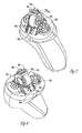
- FIG. 1A shows an embodiment of a hearing aid 100 having a faceplate 110 with an opening in the faceplate 110 for a battery compartment 120 closed by a battery door 130 that provides access to battery compartment 120, in accordance with the teachings of the present invention.
- Battery compartment 120 has sidewalls, where the sidewalls have a substantially flat port 140 and a step joint 150.
- the step joint 150, or lap joint 150 is connected to the substantially flat portion 140 and located between the opening in the faceplate 110 and the substantially flat portion 140.
- the step joint 150 forms a ridge just below the opening in the faceplate 110 for battery compartment 120.
- Battery door 130 is coupled to the faceplate 110 by a hinge.
- Battery door 130 has a body 160 and a lip 170 protruding from the body 160.
- Lip 170 is adapted to be seated on the ridge formed by the step joint 150 of the sidewalls of battery compartment 120.
- Lip 170 can have several forms including a step joint (a lap joint).
- Closing battery door 130 provides an air seal around a substantial portion of battery compartment 120. In one embodiment, the air seal extends around the three sides of battery compartment 120 with a thin slit provided on a fourth side behind the hinge that attaches battery door 130 to the faceplate 110.
- a substantially flat sidewall extends from the opening in a faceplate down into a battery compartment allowing air to flow through a gap between a battery door and the faceplate directly from or into the body of the hearing aid. This air flow, providing acoustic energy flow from inside the hearing aid back to the input to the hearing aid microphoneris a source of unwanted acoustic feedback.
- the direct path from inside or outside the hearing aid through battery compartment 120 is reduced.
- the seating of lip 170 of battery door 130 into the ridge formed by step joint 150 of the sidewall provides a seal for air flow. This substantially reduces or eliminates acoustic feedback.
- Hearing aid 100 includes standard elements as is known by those skilled in the art including a microphone 180 and a volume control 190.
- Battery compartment 120 is the region of the hearing aid in which a battery is housed.
- a battery is held in an arm of battery door 130 and is lowered into battery compartment 120 when battery door 130 is closed.
- FIG. 1B shows an embodiment of battery door 130 having body 160 and lip 170 protruding from body 160, in accordance with the teachings of the present invention.
- Lip 170 of battery door 130 substantially seals air paths between faceplate 110 and battery compartment 120 of Figure 1A.
- Lip 170 can have several forms including a lap joint.
- FIG 1C shows a top view of an embodiment of hearing aid 100 with battery door 130 removed.
- This view illustrates step joint 150 of the sidewalls.
- Step joint 150, or lap joint 150 is one form of a step portion of the sidewalls of a battery compartment that forms a ridge to which a lip of a battery door can be seated upon closing the battery door.
- the lap joint, or step joint 150 can be formed as part of a plastic molding of the hearing aid.
- Battery door 130 of Figure 1B snaps onto a hinge 115 to fasten battery door 13 0 to faceplate 110.
- Figure 1C also indicates a relative placement of microphone 180 and volume control 190 with respect to battery compartment 120.
- FIG. 1D shows another top view of an embodiment of hearing aid 100 with microphone 180, volume control 190, battery door 130 closed, and a thin slit 135.
- the thin slit 135 is located at an end of battery door 130 behind a hinge to which battery door 130 is connected. Thin slit 135 allows air into battery compartment 120 of the hearing aid 100 for proper operation of the battery. However, with battery door 130 closed, the sides of battery compartment 120 not adjacent to the thin slit 135 are essentially sealed to air flow from and into battery compartment 120. Thus, with the air flow limited to the thin slit 135, a source of acoustic feedback is greatly reduced, while maintaining proper operation conditions for the hearing aid battery.
- Figure 1E shows another top view of an embodiment of hearing aid 100 with microphone 180, volume control 190, and partially open battery door 130 attached to faceplate 110. From Figure 1E, a view is provided demonstrating the seating of lip 170 protruding from body 160 onto the ridge formed by step joint 150 of the sidewalls of battery compartment 120. Also demonstrated is the relationship of the substantially flat portion 140 of the sidewalls to step joint 150 as battery door 130 closes to provide an air seal around a substantial portion of battery compartment 120.
- a hearing aid incorporating an embodiment of a battery door seal in accordance with the teachings of the present invention has increased performance relative to a hearing aid without the door seal.
- the hearing aid incorporating an embodiment of the battery door seal provides approximately a 5 dB improvement in frequency response.
- FIG. 2 shows an embodiment of a battery door 200 holding a battery 205 and connected to a faceplate 210 for providing access to a battery compartment 220.
- Battery compartment 220 has a gasket 235 affixed to a substantially flat portion of the sidewalls of battery compartment 220.
- the sidewalls have a step joint 250 located between an opening in faceplate 210 and gasket 235 affixed to a substantially flat portion of the sidewalls.
- Battery door 200 has a body 260 and a lip 270 that protrudes from body 260.
- a second gasket 265 is affixed to sides of body 260.
- Battery door 200 holds battery 205 and lowers battery 205 into battery compartment 220 as battery door 200 is closed.
- lip 270 seats onto a ridge formed by step joint 250 and forms a seal to air flow into battery compartment 220. Further, with the battery door 200 closed; second casket 265 presses against gasket 235 to provide a further barrier to air flow from and into barrier compartment 220.
- the gaskets are rubber gaskets.
- Other materials can be used that can be configured to affix to the substantially flat portion of the sidewalls of the battery compartment and affix to the sides of the battery door body.
- the gaskets can be formed as a two shot mold.
- a two shot mold consists of molded hard plastic as the base structure with gasket material molded on the hard plastic.
- battery door 200 is molded as a hard plastic first followed by molding gasketing material 265 on the sides of the door.
- the two shot mold formation can also be applied to forming the substantially flat sidewalls of the battery compartment 220 with gasket 235.
- battery door 200 is configured to snap onto a hinge connected to faceplate 210. Further a healing aid to which battery door 200 is connected includes a slit in faceplate 210 located behind the coupling of battery door 200 to the hinge providing an opening to battery compartment 220 for air flow.
- FIG 3 shows an another embodiment of a battery door 300 holding a battery 305 and connected to a faceplate 310 for providing access to a battery compartment 320.
- Battery compartment 320 has a gasket 335 affixed to a substantially flat portion of the sidewalls of battery compartment 320 and to a step joint located between the opening in the faceplate 310 and the substantially flat portion of the sidewalls.
- Battery door 300 has a body 360 and a lip 370 that protrudes from body 360.
- a second gasket 365 is affixed to lip 370.
- Second gasket 365 is affixed to lip 370 of battery door 300 such that the second gasket 365 is seated on gasket 335 when the battery door is closed, where gasket 335 covers the step joint of the sidewalls of battery compartment 320.
- Battery door 300 holds battery 305 and lowers battery 305 into battery compartment 320 as battery door 300 is closed.
- gasket 365 of lip 370 seats onto a ridge formed by the step joint covered by gasket 335 and forms a seal to air flow from and into battery compartment 320.
- the gaskets are rubber gaskets.
- Other materials can be used that can be configured to affix to the substantially flat portion and the step portion of the sidewalls of the battery compartment 320 and affix to lip 370 of the battery door 300.
- the gaskets can be formed as a two shot mold.
- battery door 300 is molded as a hard plastic first followed by molding gasketing material 365 onto lip 370.
- the two shot mold formation can also be applied to forming the substantially flat portion and the step portion of the sidewalls of the battery compartment 320 with gasket 335.
- battery door 300 is configured to snap onto a hinge coupled to faceplate 310. Further a hearing aid to which battery door 300 is connected includes a slit in faceplate 310 located behind the coupling of battery door 300 to the hinge providing an opening to battery compartment 320 for air flow.
- FIG. 4 shows another embodiment of a battery door 400 holding a battery 405 and connected to a faceplate 410 for providing access to a battery compartment 420.
- Battery compartment 420 has sidewalls with a substantially flat portion 440 and a step joint 450.
- Step joint 450 is located between the opening in faceplate 410 and the substantially flat portion 440 of the sidewalls.
- Battery door 400 has a body 460 and a gasket 465 disposed on the top portion of battery door 400 with at least a portion of gasket 465 protruding from body 460 of battery door 400 forming a lip.
- the lip of gasket 465 is adapted to be seated on the ridge formed by step joint 450 of the sidewalls of battery compartment 420 when battery door 400 closes, providing an air seal around a substantial portion of battery compartment 420.
- Battery door 400 holds battery 405 and lowers battery 405 into battery compartment 420 as battery door 400 is closed.
- the lip of gasket 465 seats onto a ridge formed by step joint 450 and forms a seal to air flow from and into battery compartment 420.
- gasket 465 is a rubber gasket.
- Other materials can be used that can be configured to affix to top of battery door 400
- the gasket can be formed as a two shot mold.
- battery door 400 is molded as a hard plastic first followed by molding gasketing material 465 on the top of battery door 400.
- battery door 400 is configured to snap onto a hinge coupled to faceplate 410. Further a hearing aid to which battery door 400 is connected includes a slit in faceplate 410 located behind the coupling of battery door 400 to the hinge providing an opening to battery compartment 420 for air flow.
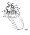
- FIG. 5 shows another embodiment of a battery door 500 holding a battery 505 and connected to a faceplate 510 for providing access to a battery compartment 520.
- Battery compartment 520 has sidewalls and an opening in the faceplate, where the sidewalls have a substantially flat portion.
- a gasket 535 is affixed to the sidewalls of battery compartment 520 .
- Gasket 535 extends from the opening in faceplate 510 down along at least a portion of the substantially flat portion of the sidewalls.
- Gasket 535 has a ridge at the opening in the faceplate.
- Battery door 500 has a body 560 and a lip 570 that protrudes from body 560. Battery door 500 holds battery 505 and lowers battery 505 into battery compartment 520 as battery door 500 is closed. When battery door 500 closes, lip 570 seats onto the ridge of gasket 535 and forms a seal to air flow from and into battery compartment 520.
- the gasket is a rubber gasket.
- Other materials can be used that can be configured to affix to the substantially flat portion of the sidewalls of the battery compartment.
- the gasket can be formed as a two shot mold.
- the substantially flat portion of the sidewalls of battery compartment 520 is molded as a hard plastic first followed by molding gasketing material 535 on the substantially flat portion of the sidewalls.
- battery door 500 is configured to snap onto a hinge coupled to faceplate 510.
- a hearing aid to which battery door 500 is connected includes a slit in faceplate 510 located behind the coupling of battery door 500 to the hinge providing an opening to battery compartment 520 for air flow,
- a hearing aid having a battery door seal that substantially reduces or eliminates unwanted air flow from and into a battery compartment of the hearing aid is provided- Further, the hearing aid having a battery door seal as described in the embodiments herein provide a hearing aid in which moisture, dirt, and body oils are eliminated or substantially reduced increasing reliability and performance of the hearing aid. Eliminating unwanted air flow removes a potential source of acoustic feedback. By eliminating or substantially reducing the unwanted air flow significant improvement is attained in the frequency response of the hearing aid. However, a complete seal that eliminates all air flow does not provide air needed for proper operation of some common batteries.
- Embodiments of a hearing aid include a battery compartment with sidewalls that have a step joint, or lap joint, formed between an opening in a faceplate to the battery compartment and a substantially flat portion of the sidewalls of the battery compartment.
- the step joint is one form for a step portion of the sidewalls to form a ridge in the sidewalls located at the opening in the faceplate.
- a door to the battery compartment has a lip that seats on a ridge formed by the step joint when the battery door closes providing an air seal around a substantial portion of the battery compartment.
- One embodiment of the lip includes a step joint formed in the battery door.
- a thin slit is provided between the faceplate and the battery door behind the end of the battery door where the battery door is coupled to the faceplate by a hinge.
Landscapes
- Health & Medical Sciences (AREA)
- General Health & Medical Sciences (AREA)
- Neurosurgery (AREA)
- Otolaryngology (AREA)
- Physics & Mathematics (AREA)
- Engineering & Computer Science (AREA)
- Acoustics & Sound (AREA)
- Signal Processing (AREA)
- Battery Mounting, Suspending (AREA)
- Hybrid Cells (AREA)
Abstract
Description
- The invention relates to hearing aid devices. Specifically, the invention relates to a battery compartment of a hearing aid.
- Hearing aids have a battery compartment for placement of a battery power source for operating the hearing aid. The battery compartment includes a battery door for providing access to the battery compartment to exchange an old battery with a new battery, when the power level of the old battery drops below a useful level.
- Unfortunately, the battery door represents a potential reliability problem. Around the battery door are thin openings or gaps. These openings provide an area in which moisture, dirt, and body oils can enter a hearing aid, causing corrosion or intermittent hearing aid behaviour By minimizing these openings into a hearing aid, reliability can greatly be increased. However, a total seal is not desirable. For example, zinc air batteries, the most common hearing aid battery, require air for normal operation.
- Another problem associated with a battery door having a poor battery door seal deals with a compromise in acoustic performance of the hearing aid. In particular, in the ear (ITE) hearing aids may allow sufficient sound pressure level (SPL) to leak from the interior of the hearing aid shell though the battery door slit to reach the microphone of the hearing aid. This leakage of acoustic energy to the microphone inlet can result in acoustic feedback, a highly undesirable outcome Furthermore, these potential reliability problems also accompany battery doors for behind the ear (BTE) hearing aids.
- What is needed is a seal around the battery compartment of a hearing aid to eliminate or substantially reduce leakage of acoustic energy that can cause acoustic feedback.
- For these and other reasons there is a need for the present invention.
- A solution to the problems as discussed above is addressed by the present invention. According to a first aspect, the present invention provides a hearing aid, comprising a faceplate; a battery compartment including an opening in the faceplate, sidewalls having a substantially flat portion, and a ridge formed by a step joint coupled to the substantially flat portion of the sidewalls and located between the opening in the faceplate and the substantially flat portion of the sidewalls; and a battery door coupled to the faceplate by a hinge, the battery door having a body and a lip protruding from the body, the lip adapted to be seated on the ridge when the battery door is closed to provide an air seal around a substantial portion of the battery compartment.
- Preferably, the hearing aid has a battery door seal that substantially reduces or eliminates unwanted air flow between the inside and outside of the hearing aid through a battery compartment. Eliminating unwanted air flow removes a potential source of acoustic feedback. By eliminating or substantially reducing the unwanted air flow significant improvement is attained in the frequency response of the hearing aid.
- In a preferred embodiment, a hearing aid includes a battery compartment with sidewalls that have a step joint formed between an opening in a faceplate to the battery compartment and a substantially flat portion of the sidewalls of the battery compartment. Additionally, a door to the battery compartment may have a lip that sets on a ridge formed by the step joint when the battery door closes, providing an air seal around a substantial portion of the battery compartment. A thin slit may be located between the faceplate and the battery door behind the end of the battery door where the battery door is connected to the faceplate by a binge to provide appropriate air flow for proper battery operation.
- According to a second aspect, the present invention provides a method for housing a battery in a hearing aid having a faceplate, comprising forming a battery compartment with sidewalls having a substantially flat portion and an opening in the faceplate; providing a ridge between the opening in the faceplate and the substantially flat portion of the sidewalls; and providing a battery door with a lip adapted to be seated on the ridge when the battery door is closed to provide an air seal around a substantial portion of the battery compartment.
- These and other embodiments, aspects, advantages, and features of the present invention will be set forth in part in the description which follows, and in part will become apparent to those skilled in the art by reference to the following description of the invention and referenced drawings or by practice of the invention. The aspects, advantages, and features of the invention are realized and attained by means of the instrumentalities, procedures. and combinations particularly pointed out in the appended claims.
- Preferred embodiments of the present invention will now be described by way of example only, and with reference to the accompanying drawings, in which:
- Figure 1A shows an embodiment of a hearing aid having a faceplate with an opening in the faceplate for a battery compartment closed by a battery door that provides access to the battery compartment, in accordance with the teachings of the present invention.
- Figure 1B shows an embodiment of a battery door having a body and a lip protruding from the body, in accordance with the teachings of the present invention.
- Figure 1C shows a top view of an embodiment of a hearing aid with its battery door removed, in accordance with the teachings of the present invention.
- Figure 1D shows another top view of an embodiment of a hearing aid with a microphone, a volume control, a battery door closed, and a thin slit, in accordance with an embodiment of the teachings of the present invention.
- Figure 1E shows another top view of an embodiment of a hearing aid with a microphone, a volume control, and a partially open battery door attached to a faceplate, in accordance with another embodiment of the teachings of the present invention.
- Figure 2 shows an embodiment of a battery door holding a battery and connected to a faceplate for providing access to a battery compartment, in accordance with the teachings of the present invention.
- Figure 3 shows an another embodiment of a battery door holding a battery and connected to a faceplate for providing access to a battery compartment, in accordance with the teachings of the present invention.
- Figure 4 shows another embodiment of a battery door holding a battery and connected to a faceplate for providing access to a battery compartment, in accordance with the teachings of the present invention.
- Figure 5 shows another embodiment of a battery door holding a battery and connected to a faceplate for providing access to a battery compartment, in accordance with an embodiment of the teachings of the present invention.
-
- The embodiments now described are described in sufficient detail to enable those skilled in the art to practice the invention, and it is to be understood that the embodiments may be combined, or that other embodiments may be utilized and that structural, logical and electrical changes may be made without departing from the Scope of the present invention. The following detailed description is, therefore, not to be taken in a limiting sense, and the scope of the present invention is defined by the appended claims and their equivalents.
- Figure 1A shows an embodiment of a
hearing aid 100 having afaceplate 110 with an opening in thefaceplate 110 for abattery compartment 120 closed by abattery door 130 that provides access tobattery compartment 120, in accordance with the teachings of the present invention.Battery compartment 120 has sidewalls, where the sidewalls have a substantiallyflat port 140 and astep joint 150. Thestep joint 150, orlap joint 150, is connected to the substantiallyflat portion 140 and located between the opening in thefaceplate 110 and the substantiallyflat portion 140. Thestep joint 150 forms a ridge just below the opening in thefaceplate 110 forbattery compartment 120. -
Battery door 130 is coupled to thefaceplate 110 by a hinge.Battery door 130 has abody 160 and alip 170 protruding from thebody 160.Lip 170 is adapted to be seated on the ridge formed by thestep joint 150 of the sidewalls ofbattery compartment 120.Lip 170 can have several forms including a step joint (a lap joint).Closing battery door 130 provides an air seal around a substantial portion ofbattery compartment 120. In one embodiment, the air seal extends around the three sides ofbattery compartment 120 with a thin slit provided on a fourth side behind the hinge that attachesbattery door 130 to thefaceplate 110. - In conventional hearing aids, a substantially flat sidewall extends from the opening in a faceplate down into a battery compartment allowing air to flow through a gap between a battery door and the faceplate directly from or into the body of the hearing aid. This air flow, providing acoustic energy flow from inside the hearing aid back to the input to the hearing aid microphoneris a source of unwanted acoustic feedback.
- In the embodiments of the present invention, the direct path from inside or outside the hearing aid through
battery compartment 120 is reduced. In one embodiment, the seating oflip 170 ofbattery door 130 into the ridge formed bystep joint 150 of the sidewall provides a seal for air flow. This substantially reduces or eliminates acoustic feedback. -
Hearing aid 100 includes standard elements as is known by those skilled in the art including amicrophone 180 and avolume control 190.Battery compartment 120 is the region of the hearing aid in which a battery is housed. In one embodiment, a battery is held in an arm ofbattery door 130 and is lowered intobattery compartment 120 whenbattery door 130 is closed. - Figure 1B shows an embodiment of
battery door 130 havingbody 160 andlip 170 protruding frombody 160, in accordance with the teachings of the present invention.Lip 170 ofbattery door 130 substantially seals air paths betweenfaceplate 110 andbattery compartment 120 of Figure 1A.Lip 170 can have several forms including a lap joint. - Figure 1C shows a top view of an embodiment of
hearing aid 100 withbattery door 130 removed. This view illustratesstep joint 150 of the sidewalls.Step joint 150, orlap joint 150, is one form of a step portion of the sidewalls of a battery compartment that forms a ridge to which a lip of a battery door can be seated upon closing the battery door. The lap joint, orstep joint 150, can be formed as part of a plastic molding of the hearing aid. -
Battery door 130 of Figure 1B snaps onto ahinge 115 to fasten battery door 13 0 tofaceplate 110. Figure 1C also indicates a relative placement ofmicrophone 180 andvolume control 190 with respect tobattery compartment 120. - Figure 1D shows another top view of an embodiment of hearing
aid 100 withmicrophone 180,volume control 190,battery door 130 closed, and athin slit 135. Thethin slit 135 is located at an end ofbattery door 130 behind a hinge to whichbattery door 130 is connected.Thin slit 135 allows air intobattery compartment 120 of thehearing aid 100 for proper operation of the battery. However, withbattery door 130 closed, the sides ofbattery compartment 120 not adjacent to thethin slit 135 are essentially sealed to air flow from and intobattery compartment 120. Thus, with the air flow limited to thethin slit 135, a source of acoustic feedback is greatly reduced, while maintaining proper operation conditions for the hearing aid battery. - Figure 1E shows another top view of an embodiment of hearing
aid 100 withmicrophone 180,volume control 190, and partiallyopen battery door 130 attached tofaceplate 110. From Figure 1E, a view is provided demonstrating the seating oflip 170 protruding frombody 160 onto the ridge formed bystep joint 150 of the sidewalls ofbattery compartment 120. Also demonstrated is the relationship of the substantiallyflat portion 140 of the sidewalls to step joint 150 asbattery door 130 closes to provide an air seal around a substantial portion ofbattery compartment 120. - A hearing aid incorporating an embodiment of a battery door seal in accordance with the teachings of the present invention has increased performance relative to a hearing aid without the door seal. For a frequency range from about 3 kHz to about 4 kHz, which is a critical frequency range with respect to the effects of acoustic feedback, the hearing aid incorporating an embodiment of the battery door seal provides approximately a 5 dB improvement in frequency response.
- Figure 2 shows an embodiment of a
battery door 200 holding abattery 205 and connected to afaceplate 210 for providing access to abattery compartment 220.Battery compartment 220 has agasket 235 affixed to a substantially flat portion of the sidewalls ofbattery compartment 220. The sidewalls have a step joint 250 located between an opening infaceplate 210 andgasket 235 affixed to a substantially flat portion of the sidewalls. -
Battery door 200 has abody 260 and alip 270 that protrudes frombody 260. Asecond gasket 265 is affixed to sides ofbody 260.Battery door 200 holdsbattery 205 and lowersbattery 205 intobattery compartment 220 asbattery door 200 is closed. - When
battery door 200 closes,lip 270 seats onto a ridge formed by step joint 250 and forms a seal to air flow intobattery compartment 220. Further, with thebattery door 200 closed;second casket 265 presses againstgasket 235 to provide a further barrier to air flow from and intobarrier compartment 220. - In one embodiment, the gaskets are rubber gaskets. Other materials can be used that can be configured to affix to the substantially flat portion of the sidewalls of the battery compartment and affix to the sides of the battery door body. Alternately, the gaskets can be formed as a two shot mold. A two shot mold consists of molded hard plastic as the base structure with gasket material molded on the hard plastic. For example,
battery door 200 is molded as a hard plastic first followed bymolding gasketing material 265 on the sides of the door. The two shot mold formation can also be applied to forming the substantially flat sidewalls of thebattery compartment 220 withgasket 235. - In one embodiment,
battery door 200 is configured to snap onto a hinge connected tofaceplate 210. Further a healing aid to whichbattery door 200 is connected includes a slit infaceplate 210 located behind the coupling ofbattery door 200 to the hinge providing an opening tobattery compartment 220 for air flow. - Figure 3 shows an another embodiment of a
battery door 300 holding abattery 305 and connected to afaceplate 310 for providing access to abattery compartment 320.Battery compartment 320 has agasket 335 affixed to a substantially flat portion of the sidewalls ofbattery compartment 320 and to a step joint located between the opening in thefaceplate 310 and the substantially flat portion of the sidewalls. -
Battery door 300 has abody 360 and alip 370 that protrudes frombody 360. Asecond gasket 365 is affixed tolip 370.Second gasket 365 is affixed tolip 370 ofbattery door 300 such that thesecond gasket 365 is seated ongasket 335 when the battery door is closed, wheregasket 335 covers the step joint of the sidewalls ofbattery compartment 320.Battery door 300 holdsbattery 305 and lowersbattery 305 intobattery compartment 320 asbattery door 300 is closed. Whenbattery door 300 closes,gasket 365 oflip 370 seats onto a ridge formed by the step joint covered bygasket 335 and forms a seal to air flow from and intobattery compartment 320. - In one embodiment, the gaskets are rubber gaskets. Other materials can be used that can be configured to affix to the substantially flat portion and the step portion of the sidewalls of the
battery compartment 320 and affix tolip 370 of thebattery door 300. Alternately, the gaskets can be formed as a two shot mold. For example,battery door 300 is molded as a hard plastic first followed bymolding gasketing material 365 ontolip 370. The two shot mold formation can also be applied to forming the substantially flat portion and the step portion of the sidewalls of thebattery compartment 320 withgasket 335. - In one embodiment,
battery door 300 is configured to snap onto a hinge coupled tofaceplate 310. Further a hearing aid to whichbattery door 300 is connected includes a slit infaceplate 310 located behind the coupling ofbattery door 300 to the hinge providing an opening tobattery compartment 320 for air flow. - Figure 4 shows another embodiment of a
battery door 400 holding abattery 405 and connected to afaceplate 410 for providing access to abattery compartment 420.Battery compartment 420 has sidewalls with a substantiallyflat portion 440 and astep joint 450. Step joint 450 is located between the opening infaceplate 410 and the substantiallyflat portion 440 of the sidewalls. -
Battery door 400 has abody 460 and agasket 465 disposed on the top portion ofbattery door 400 with at least a portion ofgasket 465 protruding frombody 460 ofbattery door 400 forming a lip. The lip ofgasket 465 is adapted to be seated on the ridge formed bystep joint 450 of the sidewalls ofbattery compartment 420 whenbattery door 400 closes, providing an air seal around a substantial portion ofbattery compartment 420.Battery door 400 holdsbattery 405 and lowersbattery 405 intobattery compartment 420 asbattery door 400 is closed. Whenbattery door 400 closes, the lip ofgasket 465 seats onto a ridge formed by step joint 450 and forms a seal to air flow from and intobattery compartment 420. - To one embodiment,
gasket 465 is a rubber gasket. Other materials can be used that can be configured to affix to top ofbattery door 400 Alternately, the gasket can be formed as a two shot mold. For example,battery door 400 is molded as a hard plastic first followed bymolding gasketing material 465 on the top ofbattery door 400. - In one embodiment,
battery door 400 is configured to snap onto a hinge coupled tofaceplate 410. Further a hearing aid to whichbattery door 400 is connected includes a slit infaceplate 410 located behind the coupling ofbattery door 400 to the hinge providing an opening tobattery compartment 420 for air flow. - Figure 5 shows another embodiment of a
battery door 500 holding abattery 505 and connected to afaceplate 510 for providing access to abattery compartment 520.Battery compartment 520 has sidewalls and an opening in the faceplate, where the sidewalls have a substantially flat portion. - A
gasket 535 is affixed to the sidewalls ofbattery compartment 520 .Gasket 535 extends from the opening infaceplate 510 down along at least a portion of the substantially flat portion of the sidewalls.Gasket 535 has a ridge at the opening in the faceplate. -
Battery door 500 has abody 560 and alip 570 that protrudes frombody 560.Battery door 500 holdsbattery 505 and lowersbattery 505 intobattery compartment 520 asbattery door 500 is closed. Whenbattery door 500 closes,lip 570 seats onto the ridge ofgasket 535 and forms a seal to air flow from and intobattery compartment 520. - In one embodiment, the gasket is a rubber gasket. Other materials can be used that can be configured to affix to the substantially flat portion of the sidewalls of the battery compartment. Alternately, the gasket can be formed as a two shot mold. For example, the substantially flat portion of the sidewalls of
battery compartment 520 is molded as a hard plastic first followed bymolding gasketing material 535 on the substantially flat portion of the sidewalls. - In one embodiment,
battery door 500 is configured to snap onto a hinge coupled tofaceplate 510. Further, a hearing aid to whichbattery door 500 is connected includes a slit infaceplate 510 located behind the coupling ofbattery door 500 to the hinge providing an opening tobattery compartment 520 for air flow, - A hearing aid having a battery door seal that substantially reduces or eliminates unwanted air flow from and into a battery compartment of the hearing aid is provided- Further, the hearing aid having a battery door seal as described in the embodiments herein provide a hearing aid in which moisture, dirt, and body oils are eliminated or substantially reduced increasing reliability and performance of the hearing aid. Eliminating unwanted air flow removes a potential source of acoustic feedback. By eliminating or substantially reducing the unwanted air flow significant improvement is attained in the frequency response of the hearing aid. However, a complete seal that eliminates all air flow does not provide air needed for proper operation of some common batteries.
- Embodiments of a hearing aid include a battery compartment with sidewalls that have a step joint, or lap joint, formed between an opening in a faceplate to the battery compartment and a substantially flat portion of the sidewalls of the battery compartment. The step joint is one form for a step portion of the sidewalls to form a ridge in the sidewalls located at the opening in the faceplate. Additionally, a door to the battery compartment has a lip that seats on a ridge formed by the step joint when the battery door closes providing an air seal around a substantial portion of the battery compartment. One embodiment of the lip includes a step joint formed in the battery door. A thin slit is provided between the faceplate and the battery door behind the end of the battery door where the battery door is coupled to the faceplate by a hinge.
- Although specific embodiments have been illustrated and described herein, it will be appreciated by those of ordinary skill in the art that any arrangement which is calculated to achieve the same purpose may be substituted for the specific embodiment shown. This application is intended to cover any adaptations or variations of the present invention. It is to be understood that the above description is intended to be illustrative, and not restrictive. Combinations of the above embodiments, and other embodiments will be apparent to those of skill in the art upon reviewing the above description. The scope of the invention includes any other applications in which the above structures and fabrication methods are used. The scope of the invention should be determined with reference to the appended claims, along with the full scope of equivalents to which such claims are entitled.
Claims (31)
- A hearing aid, comprising:a faceplate;a battery compartment including an opening in the faceplate, sidewalls having a substantially flat portion, and a ridge formed by a step joint coupled to the substantially flat portion of the sidewalls and located between the opening in the faceplate and the substantially flat portion of the sidewalls; anda battery door coupled to the faceplate by a hinge, the battery door having a body and a lip protruding from the body, the lip adapted to be seated on the ridge when the battery door is closed to provide an air seal around a substantial portion of the battery compartment.
- The hearing aid according to claim 1, wherein the battery door is configured to snap onto the hinge.
- The hearing aid according to any of the preceding claims, wherein the hearing aid further includes a slit in the faceplate located behind the hinge coupling the battery door to the faceplate to provide an opening to the battery compartment for air flow.
- The hearing aid according to any of the preceding claims, wherein the sidewalls comprises the substantially flat portion and a step portion forming the ridge.
- The hearing aid according to any of the preceding claims, wherein the faceplate, the battery compartment, and the battery door are plastic.
- The hearing aid according to any of claims 1 - 4, further comprising a first gasket affixed to the battery compartment and a second gasket affixed to the battery door to provide a barrier to air flow from and into the battery compartment when the battery door is closed.
- The hearing aid according to claim 6, wherein the first gasket is affixed to the substantially flat portion of the sidewalls, and the second gasket is affixed to sides of the body of the battery door, the sides of the battery door body substantially parallel to the substantially flat portion of the sidewalls when the battery door is closed.
- The hearing aid according to claim 7, wherein the substantially flat portion of the sidewalls is moulded of hard plastic, the first gasket is moulded on the hard plastic of the substantially flat portion of the sidewalls, the battery door is moulded of hard plastic, and the second gasket is moulded on the hard plastic of the sides of the battery door body.
- The hearing aid according to claim 6, wherein the first gasket is affixed to both the substantially flat portion and the step portion of the sidewalls, and the second gasket is affixed to the lip of the battery door such that the second gasket is seated on the first gasket when the battery door is closed.
- The hearing aid according to claim 9, wherein both the substantially flat portion and the step portion of the sidewalls are moulded of hard plastic, the first gasket is moulded on the hard plastic of both the substantially flat portion and the step portion of the sidewalls, the lip of the door is moulded of hard plastic, and the second gasket is moulded on the hard plastic of the lip of the battery door.
- The hearing aid according to any of claims 7 and 9, wherein the first gasket and the second gasket are rubber gaskets.
- The hearing aid according to any of claims 1 - 3, further comprising a gasket affixed to the sidewalls, the gasket extending from the opening in the faceplate down along at least a portion of the substantially flat portion of the sidewalls, the gasket including the ridge.
- The hearing aid according to claim 12, wherein the sidewalls are moulded of hard plastic, and the gasket is moulded on the hard plastic of the sidewalls.
- The hearing aid according to claim 12, wherein the gasket is a rubber gasket.
- The hearing aid according to any of claims 1 - 4 and 12 - 14, wherein the battery door comprises the body, a top portion, and a gasket disposed on the top portion, at least a portion of the gasket protruding from the body of the battery door to form the lip.
- The hearing aid according to claim 15, wherein the battery door is moulded of hard plastic, and the gasket disposed on the top portion of the battery door is moulded on the hard plastic of the top portion of the battery door.
- The hearing aid according to claim 15, wherein the gasket disposed on the top portion of the battery door is a rubber gasket.
- A method for housing a battery in a hearing aid having a faceplate, comprising:forming a battery compartment with sidewalls having a substantially flat portion and an opening in the faceplate;providing a ridge between the opening in the faceplate and the substantially flat portion of the sidewalls; andproviding a battery door with a lip adapted to be seated on the ridge when the battery door is closed to provide an air seal around a substantial portion of the battery compartment.
- The method according to claim 18, further comprising coupling the battery door to the faceplate with a hinge.
- The method according to any of claims 18 and 19, further comprising providing an opening to the battery compartment for air flow.
- The method according to claim 20, wherein providing an opening to the battery compartment for air flow comprises providing a slit in the faceplate located behind the hinge.
- The method according to any of claims 18 - 21, wherein providing the ridge comprises providing the sidewalls with a step portion connected the substantially flat portion, the step portion forming the ridge.
- The method according to claim 22, further comprising affixing a first gasket to the battery compartment and affixing a second gasket to the battery door to provide a barrier to air flow from and into the battery compartment when the battery door is closed.
- The method according to claim 23, wherein affixing the first gasket to the battery compartment comprises affixing the first gasket to the substantially flat portion of the sidewalls, and affixing the second gasket to the battery door comprises affixing the second gasket to the sides of a body of the battery door, the sides of the battery door body substantially parallel to the substantially flat portion of the sidewalls when the battery door is closed.
- The method according to claim 24, wherein affixing the first gasket to the substantially flat portion of the sidewalls comprising moulding the substantially flat portion of the sidewalls as hard plastic and moulding the first gasket on the hard plastic of the substantially flat portion of the sidewalls, and affixing the second gasket to the battery door comprises moulding the battery door as hard plastic and moulding the second gasket on the hard plastic of the sides of the battery door body.
- The method according to claim 23, wherein affixing the first gasket to the battery compartment comprises affixing the first gasket to both the substantially flat portion and the step portion of the sidewalls, and affixing the second gasket to the battery door comprises affixing the second gasket to the lip of the battery door such that the second gasket is seated on the first gasket when the battery door is closed.
- The method according to claim 26, wherein affixing the first gasket to the substantially flat portion of the sidewalls comprises moulding both the substantially flat portion and the step portion of the sidewalls as hard plastic and moulding the first gasket on the hard plastic of both the substantially flat portion and the step portion of the sidewalls, and affixing the second gasket to the battery door comprises moulding the lip of the door as hard plastic and moulding the second gasket on the hard plastic of the lip of the battery door.
- The method according to any of claims 18 - 21, further comprising affixing a gasket to the sidewalls, the gasket extending from the opening in the faceplate down along at least a portion of the substantially flat portion of the sidewalls, and wherein providing the ridge comprises forming the ridge with a portion of the gasket.
- The method according to claim 28, wherein affixing the gasket to the sidewalls comprises moulding the sidewalls as hard plastic and moulding the gasket on the hard plastic of the sidewalls.
- The hearing aid according to any of claims 18 - 22, 28, and 29, wherein providing the battery door with the lip comprises disposing a gasket on a top portion of the battery door with at least a portion of the gasket protruding from the top portion of the battery door to form the lip.
- The method according to claim 30, wherein disposing the gasket on the top portion of the battery door comprises moulding the battery door as hard plastic and moulding the gasket on the hard plastic of the top portion of the battery door.
Applications Claiming Priority (2)
| Application Number | Priority Date | Filing Date | Title |
|---|---|---|---|
| US10/284,878 US7171014B2 (en) | 2002-10-31 | 2002-10-31 | Hearing aid battery door seal |
| US284878 | 2002-10-31 |
Publications (3)
| Publication Number | Publication Date |
|---|---|
| EP1416766A2 true EP1416766A2 (en) | 2004-05-06 |
| EP1416766A3 EP1416766A3 (en) | 2007-03-21 |
| EP1416766B1 EP1416766B1 (en) | 2011-09-14 |
Family
ID=32093538
Family Applications (1)
| Application Number | Title | Priority Date | Filing Date |
|---|---|---|---|
| EP03256911A Revoked EP1416766B1 (en) | 2002-10-31 | 2003-10-31 | Hearing aid battery door seal |
Country Status (5)
| Country | Link |
|---|---|
| US (1) | US7171014B2 (en) |
| EP (1) | EP1416766B1 (en) |
| AT (1) | ATE524935T1 (en) |
| CA (1) | CA2447284A1 (en) |
| DK (1) | DK1416766T3 (en) |
Cited By (3)
| Publication number | Priority date | Publication date | Assignee | Title |
|---|---|---|---|---|
| NL1030649C2 (en) * | 2005-12-12 | 2007-06-13 | Exsilent Res Bv | Hearing aid. |
| EP2582157A1 (en) * | 2011-09-29 | 2013-04-17 | Siemens Medical Instruments Pte. Ltd. | Hearing aid with sealing means |
| EP3068145A1 (en) * | 2015-03-11 | 2016-09-14 | Sivantos Pte. Ltd. | Hearing aid |
Families Citing this family (12)
| Publication number | Priority date | Publication date | Assignee | Title |
|---|---|---|---|---|
| WO2006071210A1 (en) * | 2003-12-24 | 2006-07-06 | Cochlear Americas | Transformable speech processor module for a hearing prosthesis |
| US8660658B2 (en) | 2004-05-05 | 2014-02-25 | Advanced Bionics Ag | Speech processor cases |
| US7630772B1 (en) | 2004-05-05 | 2009-12-08 | Advanced Bionics, Llc | Methods of converting a behind-the-ear speech processor unit into a body worn speech processor unit |
| US8180084B2 (en) * | 2007-03-21 | 2012-05-15 | Starkey Laboratories, Inc. | Integrated battery door and switch |
| DE102010041263A1 (en) | 2010-09-23 | 2012-03-29 | Siemens Medical Instruments Pte. Ltd. | Housing of hearing aid, has sealing lip element whose preset end is elastically deformed in sealing condition, to have bend portion so that element surface is located on partial surface of housing portion |
| USD693008S1 (en) | 2013-03-09 | 2013-11-05 | Advanced Bionics Ag | Sound processor enclosure exterior |
| DK3422741T3 (en) * | 2014-04-07 | 2020-08-03 | Oticon As | HEARING AID DEVICE THAT HAS A BATTERY DRAWER |
| US10720275B2 (en) | 2017-10-31 | 2020-07-21 | Starkey Laboratories, Inc. | Detent assembly |
| USD984646S1 (en) * | 2021-05-13 | 2023-04-25 | Dylan Arthur Garber | Hearing aid |
| USD984647S1 (en) * | 2021-06-22 | 2023-04-25 | Dylan Arthur Garber | Hearing aid |
| USD983377S1 (en) * | 2021-09-17 | 2023-04-11 | Xiamen Retone Hearing Technology Co., Ltd. | Hearing aid |
| USD983378S1 (en) * | 2021-09-17 | 2023-04-11 | Xiamen Retone Hearing Technology Co., Ltd. | Hearing aid |
Citations (1)
| Publication number | Priority date | Publication date | Assignee | Title |
|---|---|---|---|---|
| CH667766A5 (en) | 1985-02-02 | 1988-10-31 | Rexton Holding Ag | Miniature hearing aid ear insert - has amplifier attached to inside of cover providing access to battery compartment |
Family Cites Families (13)
| Publication number | Priority date | Publication date | Assignee | Title |
|---|---|---|---|---|
| JPS60261296A (en) | 1984-06-08 | 1985-12-24 | Rion Co Ltd | behind-the-ear hearing aid |
| US4598177A (en) * | 1985-01-16 | 1986-07-01 | Sears, Roebuck, & Co. | Hearing aid with self-contained battery compartment and volume control |
| JPS628446A (en) | 1985-07-04 | 1987-01-16 | Matsushita Electric Ind Co Ltd | Hearing aid storage case |
| DE4343702C1 (en) | 1993-12-21 | 1995-03-09 | Siemens Audiologische Technik | Hearing aid worn on the head |
| DK0704143T3 (en) | 1994-04-08 | 2000-11-06 | Beltone Netherlands B V | In-ear hearing aid with elastic seal |
| IT1272245B (en) * | 1994-05-06 | 1997-06-16 | Coselgi Spa | IMPROVEMENT IN DEEP INSERT INTRACANAL ACOUSTIC PROSTHESIS OR PERITIMPANE MICROPROTESIS |
| US5799095A (en) * | 1996-04-30 | 1998-08-25 | Siemens Hearing Instruments, Inc. | Beside-the-door programming system for programming hearing aids |
| US6088465A (en) * | 1996-04-30 | 2000-07-11 | Siemens Hearing Instruments, Inc. | Door-dependent system for enabling and adjusting options on hearing aids |
| DK42197A (en) * | 1997-04-15 | 1998-10-16 | Toepholm & Westermann | Compact modulated in-ear hearing aid |
| US6144749A (en) * | 1998-04-08 | 2000-11-07 | Starkey Laboratories, Inc. | Hearing aid faceplate and battery compartment |
| US6167141A (en) | 1998-04-30 | 2000-12-26 | Beltone Electronics Corporation | Multimaterial hearing aid housing |
| DE19825998C2 (en) | 1998-06-10 | 2003-01-30 | Siemens Audiologische Technik | Hearing aid worn on the head |
| US6393130B1 (en) | 1998-10-26 | 2002-05-21 | Beltone Electronics Corporation | Deformable, multi-material hearing aid housing |
-
2002
- 2002-10-31 US US10/284,878 patent/US7171014B2/en not_active Expired - Lifetime
-
2003
- 2003-10-30 CA CA002447284A patent/CA2447284A1/en not_active Abandoned
- 2003-10-31 EP EP03256911A patent/EP1416766B1/en not_active Revoked
- 2003-10-31 DK DK03256911.3T patent/DK1416766T3/en active
- 2003-10-31 AT AT03256911T patent/ATE524935T1/en not_active IP Right Cessation
Patent Citations (1)
| Publication number | Priority date | Publication date | Assignee | Title |
|---|---|---|---|---|
| CH667766A5 (en) | 1985-02-02 | 1988-10-31 | Rexton Holding Ag | Miniature hearing aid ear insert - has amplifier attached to inside of cover providing access to battery compartment |
Cited By (5)
| Publication number | Priority date | Publication date | Assignee | Title |
|---|---|---|---|---|
| NL1030649C2 (en) * | 2005-12-12 | 2007-06-13 | Exsilent Res Bv | Hearing aid. |
| US8699736B2 (en) | 2005-12-12 | 2014-04-15 | Exsilent Research B.V. | Hearing aid |
| US9838808B2 (en) | 2005-12-12 | 2017-12-05 | Exsilent Research B.V. | Hearing aid |
| EP2582157A1 (en) * | 2011-09-29 | 2013-04-17 | Siemens Medical Instruments Pte. Ltd. | Hearing aid with sealing means |
| EP3068145A1 (en) * | 2015-03-11 | 2016-09-14 | Sivantos Pte. Ltd. | Hearing aid |
Also Published As
| Publication number | Publication date |
|---|---|
| EP1416766A3 (en) | 2007-03-21 |
| DK1416766T3 (en) | 2011-12-12 |
| ATE524935T1 (en) | 2011-09-15 |
| US7171014B2 (en) | 2007-01-30 |
| CA2447284A1 (en) | 2004-04-30 |
| US20040086142A1 (en) | 2004-05-06 |
| EP1416766B1 (en) | 2011-09-14 |
Similar Documents
| Publication | Publication Date | Title |
|---|---|---|
| US7171014B2 (en) | Hearing aid battery door seal | |
| US5889874A (en) | Hearing aid device to be worn in the ear | |
| US20210258677A1 (en) | Canal-Type Earphone having Pressure Equilibrium Structure | |
| CA2377449C (en) | Behind-the-ear hearing device | |
| US8379895B2 (en) | Hearing aid device | |
| US5204907A (en) | Noise cancelling microphone and boot mounting arrangement | |
| US6661902B1 (en) | Loudspeaker with a front-mounted sealing element and method of manufacturing the same | |
| US20040240695A1 (en) | Hearing aid | |
| US6655698B2 (en) | Sealing member having magnet | |
| US6879696B1 (en) | In-ear hearing aid and method for its manufacture | |
| AU4740100A (en) | Electric/acoustic transducer module, intra-aural hearing-aid and method for producing an intra-aural hearing aid | |
| KR101952906B1 (en) | Acoustic device having multiple vibration plates | |
| JP4911089B2 (en) | Packing, waterproof structure using the packing, and electronic device provided with the waterproof structure using the packing | |
| US20230269505A1 (en) | Integrated loudspeaker assembly | |
| ATE92703T1 (en) | IN-THE-EAR HEARING AID WITH SOUND COMPENSATION CHANNEL. | |
| CN212413400U (en) | Independent cavity earphones | |
| EP0806882A3 (en) | Sub-woofer loudspeaker enclosure | |
| JP2000264095A (en) | Duct structure for vehicle | |
| EP1128462B1 (en) | Waterproofing and gas-permeable case construction of satellite-broadcast receiving converter | |
| JP3193102B2 (en) | Automotive glass run | |
| CN211584906U (en) | Waterproof casing and applied this waterproof casing's defibrillator | |
| US6922874B2 (en) | Housing cover for electronic microdevices | |
| CN216795283U (en) | Hearing aid with subdivision structure | |
| KR102735032B1 (en) | Clip for door weather strip | |
| CN219908320U (en) | Door sealing structure and clothes dryer |
Legal Events
| Date | Code | Title | Description |
|---|---|---|---|
| PUAI | Public reference made under article 153(3) epc to a published international application that has entered the european phase |
Free format text: ORIGINAL CODE: 0009012 |
|
| AK | Designated contracting states |
Kind code of ref document: A2 Designated state(s): AT BE BG CH CY CZ DE DK EE ES FI FR GB GR HU IE IT LI LU MC NL PT RO SE SI SK TR |
|
| AX | Request for extension of the european patent |
Extension state: AL LT LV MK |
|
| PUAL | Search report despatched |
Free format text: ORIGINAL CODE: 0009013 |
|
| AK | Designated contracting states |
Kind code of ref document: A3 Designated state(s): AT BE BG CH CY CZ DE DK EE ES FI FR GB GR HU IE IT LI LU MC NL PT RO SE SI SK TR |
|
| AX | Request for extension of the european patent |
Extension state: AL LT LV MK |
|
| 17P | Request for examination filed |
Effective date: 20070823 |
|
| 17Q | First examination report despatched |
Effective date: 20071001 |
|
| AKX | Designation fees paid |
Designated state(s): AT BE BG CH CY CZ DE DK EE ES FI FR GB GR HU IE IT LI LU MC NL PT RO SE SI SK TR |
|
| GRAP | Despatch of communication of intention to grant a patent |
Free format text: ORIGINAL CODE: EPIDOSNIGR1 |
|
| GRAS | Grant fee paid |
Free format text: ORIGINAL CODE: EPIDOSNIGR3 |
|
| GRAA | (expected) grant |
Free format text: ORIGINAL CODE: 0009210 |
|
| AK | Designated contracting states |
Kind code of ref document: B1 Designated state(s): AT BE BG CH CY CZ DE DK EE ES FI FR GB GR HU IE IT LI LU MC NL PT RO SE SI SK TR |
|
| REG | Reference to a national code |
Ref country code: GB Ref legal event code: FG4D |
|
| REG | Reference to a national code |
Ref country code: CH Ref legal event code: NV Representative=s name: RITSCHER & PARTNER AG Ref country code: CH Ref legal event code: EP |
|
| REG | Reference to a national code |
Ref country code: IE Ref legal event code: FG4D |
|
| REG | Reference to a national code |
Ref country code: DE Ref legal event code: R096 Ref document number: 60338348 Country of ref document: DE Effective date: 20111201 |
|
| REG | Reference to a national code |
Ref country code: NL Ref legal event code: T3 |
|
| REG | Reference to a national code |
Ref country code: DK Ref legal event code: T3 |
|
| PG25 | Lapsed in a contracting state [announced via postgrant information from national office to epo] |
Ref country code: SE Free format text: LAPSE BECAUSE OF FAILURE TO SUBMIT A TRANSLATION OF THE DESCRIPTION OR TO PAY THE FEE WITHIN THE PRESCRIBED TIME-LIMIT Effective date: 20110914 Ref country code: FI Free format text: LAPSE BECAUSE OF FAILURE TO SUBMIT A TRANSLATION OF THE DESCRIPTION OR TO PAY THE FEE WITHIN THE PRESCRIBED TIME-LIMIT Effective date: 20110914 |
|
| PG25 | Lapsed in a contracting state [announced via postgrant information from national office to epo] |
Ref country code: SI Free format text: LAPSE BECAUSE OF FAILURE TO SUBMIT A TRANSLATION OF THE DESCRIPTION OR TO PAY THE FEE WITHIN THE PRESCRIBED TIME-LIMIT Effective date: 20110914 Ref country code: CY Free format text: LAPSE BECAUSE OF FAILURE TO SUBMIT A TRANSLATION OF THE DESCRIPTION OR TO PAY THE FEE WITHIN THE PRESCRIBED TIME-LIMIT Effective date: 20110914 Ref country code: AT Free format text: LAPSE BECAUSE OF FAILURE TO SUBMIT A TRANSLATION OF THE DESCRIPTION OR TO PAY THE FEE WITHIN THE PRESCRIBED TIME-LIMIT Effective date: 20110914 Ref country code: GR Free format text: LAPSE BECAUSE OF FAILURE TO SUBMIT A TRANSLATION OF THE DESCRIPTION OR TO PAY THE FEE WITHIN THE PRESCRIBED TIME-LIMIT Effective date: 20111215 |
|
| REG | Reference to a national code |
Ref country code: AT Ref legal event code: MK05 Ref document number: 524935 Country of ref document: AT Kind code of ref document: T Effective date: 20110914 |
|
| PG25 | Lapsed in a contracting state [announced via postgrant information from national office to epo] |
Ref country code: BE Free format text: LAPSE BECAUSE OF FAILURE TO SUBMIT A TRANSLATION OF THE DESCRIPTION OR TO PAY THE FEE WITHIN THE PRESCRIBED TIME-LIMIT Effective date: 20110914 |
|
| PG25 | Lapsed in a contracting state [announced via postgrant information from national office to epo] |
Ref country code: SK Free format text: LAPSE BECAUSE OF FAILURE TO SUBMIT A TRANSLATION OF THE DESCRIPTION OR TO PAY THE FEE WITHIN THE PRESCRIBED TIME-LIMIT Effective date: 20110914 Ref country code: CZ Free format text: LAPSE BECAUSE OF FAILURE TO SUBMIT A TRANSLATION OF THE DESCRIPTION OR TO PAY THE FEE WITHIN THE PRESCRIBED TIME-LIMIT Effective date: 20110914 |
|
| PG25 | Lapsed in a contracting state [announced via postgrant information from national office to epo] |
Ref country code: MC Free format text: LAPSE BECAUSE OF NON-PAYMENT OF DUE FEES Effective date: 20111031 Ref country code: PT Free format text: LAPSE BECAUSE OF FAILURE TO SUBMIT A TRANSLATION OF THE DESCRIPTION OR TO PAY THE FEE WITHIN THE PRESCRIBED TIME-LIMIT Effective date: 20120116 Ref country code: EE Free format text: LAPSE BECAUSE OF FAILURE TO SUBMIT A TRANSLATION OF THE DESCRIPTION OR TO PAY THE FEE WITHIN THE PRESCRIBED TIME-LIMIT Effective date: 20110914 Ref country code: RO Free format text: LAPSE BECAUSE OF FAILURE TO SUBMIT A TRANSLATION OF THE DESCRIPTION OR TO PAY THE FEE WITHIN THE PRESCRIBED TIME-LIMIT Effective date: 20110914 Ref country code: IT Free format text: LAPSE BECAUSE OF FAILURE TO SUBMIT A TRANSLATION OF THE DESCRIPTION OR TO PAY THE FEE WITHIN THE PRESCRIBED TIME-LIMIT Effective date: 20110914 |
|
| PLBI | Opposition filed |
Free format text: ORIGINAL CODE: 0009260 |
|
| PLAB | Opposition data, opponent's data or that of the opponent's representative modified |
Free format text: ORIGINAL CODE: 0009299OPPO |
|
| PLAX | Notice of opposition and request to file observation + time limit sent |
Free format text: ORIGINAL CODE: EPIDOSNOBS2 |
|
| 26 | Opposition filed |
Opponent name: OTICON A/S / GN RESOUND A/S / WIDEX A/S Effective date: 20120614 |
|
| REG | Reference to a national code |
Ref country code: IE Ref legal event code: MM4A |
|
| R26 | Opposition filed (corrected) |
Opponent name: OTICON A/S / GN RESOUND A/S / WIDEX A/S Effective date: 20120614 |
|
| REG | Reference to a national code |
Ref country code: DE Ref legal event code: R026 Ref document number: 60338348 Country of ref document: DE Effective date: 20120614 |
|
| PG25 | Lapsed in a contracting state [announced via postgrant information from national office to epo] |
Ref country code: IE Free format text: LAPSE BECAUSE OF NON-PAYMENT OF DUE FEES Effective date: 20111031 |
|
| PLAF | Information modified related to communication of a notice of opposition and request to file observations + time limit |
Free format text: ORIGINAL CODE: EPIDOSCOBS2 |
|
| PLBB | Reply of patent proprietor to notice(s) of opposition received |
Free format text: ORIGINAL CODE: EPIDOSNOBS3 |
|
| PG25 | Lapsed in a contracting state [announced via postgrant information from national office to epo] |
Ref country code: ES Free format text: LAPSE BECAUSE OF FAILURE TO SUBMIT A TRANSLATION OF THE DESCRIPTION OR TO PAY THE FEE WITHIN THE PRESCRIBED TIME-LIMIT Effective date: 20111225 |
|
| PG25 | Lapsed in a contracting state [announced via postgrant information from national office to epo] |
Ref country code: LU Free format text: LAPSE BECAUSE OF NON-PAYMENT OF DUE FEES Effective date: 20111031 |
|
| PG25 | Lapsed in a contracting state [announced via postgrant information from national office to epo] |
Ref country code: BG Free format text: LAPSE BECAUSE OF FAILURE TO SUBMIT A TRANSLATION OF THE DESCRIPTION OR TO PAY THE FEE WITHIN THE PRESCRIBED TIME-LIMIT Effective date: 20111214 |
|
| PG25 | Lapsed in a contracting state [announced via postgrant information from national office to epo] |
Ref country code: TR Free format text: LAPSE BECAUSE OF FAILURE TO SUBMIT A TRANSLATION OF THE DESCRIPTION OR TO PAY THE FEE WITHIN THE PRESCRIBED TIME-LIMIT Effective date: 20110914 |
|
| PG25 | Lapsed in a contracting state [announced via postgrant information from national office to epo] |
Ref country code: HU Free format text: LAPSE BECAUSE OF FAILURE TO SUBMIT A TRANSLATION OF THE DESCRIPTION OR TO PAY THE FEE WITHIN THE PRESCRIBED TIME-LIMIT Effective date: 20110914 |
|
| REG | Reference to a national code |
Ref country code: CH Ref legal event code: PFA Owner name: STARKEY LABORATORIES, INC., US Free format text: FORMER OWNER: STARKEY LABORATORIES, INC., US |
|
| PGFP | Annual fee paid to national office [announced via postgrant information from national office to epo] |
Ref country code: DK Payment date: 20141027 Year of fee payment: 12 |
|
| PGFP | Annual fee paid to national office [announced via postgrant information from national office to epo] |
Ref country code: GB Payment date: 20141027 Year of fee payment: 12 Ref country code: CH Payment date: 20141027 Year of fee payment: 12 Ref country code: FR Payment date: 20141017 Year of fee payment: 12 Ref country code: DE Payment date: 20141029 Year of fee payment: 12 |
|
| RDAF | Communication despatched that patent is revoked |
Free format text: ORIGINAL CODE: EPIDOSNREV1 |
|
| REG | Reference to a national code |
Ref country code: DE Ref legal event code: R103 Ref document number: 60338348 Country of ref document: DE Ref country code: DE Ref legal event code: R064 Ref document number: 60338348 Country of ref document: DE |
|
| PGFP | Annual fee paid to national office [announced via postgrant information from national office to epo] |
Ref country code: NL Payment date: 20141026 Year of fee payment: 12 |
|
| RDAG | Patent revoked |
Free format text: ORIGINAL CODE: 0009271 |
|
| STAA | Information on the status of an ep patent application or granted ep patent |
Free format text: STATUS: PATENT REVOKED |
|
| REG | Reference to a national code |
Ref country code: CH Ref legal event code: PLX |
|
| 27W | Patent revoked |
Effective date: 20150214 |
|
| GBPR | Gb: patent revoked under art. 102 of the ep convention designating the uk as contracting state |
Effective date: 20150214 |
|
| REG | Reference to a national code |
Ref country code: DE Ref legal event code: R107 Ref document number: 60338348 Country of ref document: DE |
|
| PG25 | Lapsed in a contracting state [announced via postgrant information from national office to epo] |
Ref country code: LI Free format text: LAPSE BECAUSE OF THE APPLICANT RENOUNCES Effective date: 20110914 Ref country code: CH Free format text: LAPSE BECAUSE OF THE APPLICANT RENOUNCES Effective date: 20110914 |