EP1416515A2 - Ion trap device and its tuning method - Google Patents
Ion trap device and its tuning method Download PDFInfo
- Publication number
- EP1416515A2 EP1416515A2 EP03020905A EP03020905A EP1416515A2 EP 1416515 A2 EP1416515 A2 EP 1416515A2 EP 03020905 A EP03020905 A EP 03020905A EP 03020905 A EP03020905 A EP 03020905A EP 1416515 A2 EP1416515 A2 EP 1416515A2
- Authority
- EP
- European Patent Office
- Prior art keywords
- high voltage
- ion trap
- resonance frequency
- trap device
- resonant circuit
- Prior art date
- Legal status (The legal status is an assumption and is not a legal conclusion. Google has not performed a legal analysis and makes no representation as to the accuracy of the status listed.)
- Granted
Links
Images
Classifications
-
- H—ELECTRICITY
- H01—ELECTRIC ELEMENTS
- H01J—ELECTRIC DISCHARGE TUBES OR DISCHARGE LAMPS
- H01J49/00—Particle spectrometers or separator tubes
- H01J49/26—Mass spectrometers or separator tubes
- H01J49/34—Dynamic spectrometers
- H01J49/42—Stability-of-path spectrometers, e.g. monopole, quadrupole, multipole, farvitrons
- H01J49/4205—Device types
- H01J49/424—Three-dimensional ion traps, i.e. comprising end-cap and ring electrodes
-
- H—ELECTRICITY
- H01—ELECTRIC ELEMENTS
- H01J—ELECTRIC DISCHARGE TUBES OR DISCHARGE LAMPS
- H01J49/00—Particle spectrometers or separator tubes
- H01J49/02—Details
- H01J49/022—Circuit arrangements, e.g. for generating deviation currents or voltages ; Components associated with high voltage supply
Definitions
- the present invention relates to an ion trap device in which ions are trapped with a three-dimensional quadrupole electric field.
- an ion trap device which may also be called simply as an "ion trap” are used for ion trap mass spectrometers, for the ion source of time-of-flight mass spectrometers, and for other ion analyzers.
- ions are trapped by a three-dimensional quadrupole electric field formed by a combination of an RF (radio frequency) electric field and a DC (direct current) electric field.
- RF radio frequency
- DC direct current
- ion trap device including one using electrodes having hyperboloid-of-revolution inner surfaces, and another using a cylindrical electrode and a pair of circular plate electrodes placed at both ends of the cylindrical electrodes.
- the former one having the hyperboloid-of-revolution inner surfaces can form a larger ion trapping region in the space surrounded by the electrodes, and the latter one using the cylindrical and circular plate electrodes has rather narrower ion trapping region.
- the electrode surrounding circularly the ion trapping space is called a ring electrode, and the electrodes placed at both ends of the ring electrode are called end cap electrodes.
- the RF voltage is applied to the ring electrode to form the trapping electric field.
- the mass to charge ratio of an ion determines whether it is securely and stably trapped in the ion trapping space, or it moves irregularly and collides with an inner surface of the electrodes or is ejected outside through an opening of the electrodes.
- the kinetics of the ions in the ion trapping space is described in detail in, for example, R. E. March and R. J. Hughes, "Quadrupole Storage Mass Spectrometry", John Wiley & Sons, 1989, pp. 31-110.
- a coil is connected to the ring electrode, where the inductance of the coil, the capacitance between the ring electrode and the pair of end cap electrodes and the capacitance of all the other elements constitute an LC resonant circuit.
- an RF driver or an RF exciting circuit
- a large amplitude RF voltage can be applied to the ring electrode with a small amplitude driving voltage owing to the high Q value of the LC resonant circuit.
- a tuning circuit including a variable capacitor is normally used to make the resonance frequency of the LC circuit coincide with the frequency of the RF driver.
- the coil When the temperature rises, the coil may swell and its inductance may change, or the capacitance of the variable capacitor may change. This causes the resonance frequency of the resonant circuit to shift from that of the RF driver.
- a high voltage switch is connected to the ring electrode. When the RF high voltage is changed, the capacitance of the high voltage switch may change and the resonance may break.
- a feedback control is incorporated to fix the amplitude of the RF high voltage to a target value by adjusting the output voltage of the RF driver, so that the amplitude of the RF high voltage is stable irrespective of the shift of the resonance frequency.
- the timing when the ions are ejected from the ion trapping space is related to the phase of the RF high voltage. If there is a shift in the phase, the position of a peak or peaks of the mass spectrum shifts accordingly.
- the position of a peak or peaks of the mass spectrum also shifts if there is a shift in the phase of the RF high voltage because ion's energy and direction of motion at a timing of extraction is closely related to the phase.
- Such a problem can be solved, in principle, by monitoring (not the output of the RF driver but) the RF high voltage which is generated through amplification by resonance, detecting the phase of the RF high voltage directly, and then using the detected phase as the basis of the control. But, actually, it is very difficult to always detect an exact phase of the RF high voltage which alters in many ways. Even if it is possible in any way, it is too expensive to be practical. Another problem is that installing such a function to an existing mass spectrometer is practically impossible.
- the present invention addresses the problem, and an object of the invention is to decrease the shift in the phase difference between the output of the RF driver and the RF high voltage. This will alleviate or prevent deterioration of the mass analysis or other processings using the ion trap device caused by the shift in the phase of the RF high voltage.
- an ion trap device includes:
- the tuning circuit is adjusted so that the resonance frequency of the resonant circuit is shifted from the driving frequency.
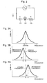
- Fig. 2 shows a model diagram of an LCR series-resonance circuit.
- the capacitor 101 representative of the overall capacitance of the circuit including the capacitance formed between the electrodes is C.
- the inductance of the coil 102 is L, and the effective resistance 103 of the resonant circuit is R.
- the angular frequency of the driving voltage (output) of the RF driver 100 is ⁇ , and the angular resonance frequency of the resonant circuit is ⁇ 0 .
- the impedance Z reaches its minimum value of R.
- the Q-value of the resonant circuit is set at around 100-300.
- the resonance frequency of the resonant circuit which is used to apply the RF high voltage to one of the electrodes of the ion trap device, is deliberately shifted from the frequency of the RF driver (driving frequency). This reduces the influence of the deviation in the resonance frequency caused by the change in the RF high voltage on the shift in the phase difference between the output of the RF driver and the RF high voltage. This minimizes the degradation of various performances of the ion trap device relating to the phase difference, such as the shift in the peaks of the mass spectrum and enhances the sensitivity and precision of the mass analysis of the mass spectrometers using the ion trap device.
- the resonant circuit may not be stable unless the shift of the resonance frequency from the resonance condition is made in a proper direction.
- the effective capacitance of the semiconductor device increases as the RF voltage increases, which leads to the decrease in the resonance frequency of the resonant circuit.
- the resonance frequency of the resonant circuit is shifted in the direction of increasing frequency by decreasing the capacitance of the resonant circuit. If the amplitude of the RF high voltage is increased, the capacitance increases, which brings the resonant circuit toward the resonance condition. This increases the gain of the resonant circuit, and destabilize the resonance due to the positive feedback phenomenon.
- the tuning procedure should shift the resonance frequency of the resonant circuit in the same direction. This stabilizes the resonance.
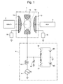
- FIG. 1 schematically shows the main part of the mass spectrometer, in which the ion trap device 1 is composed of a ring electrode 11 and a pair of end cap electrodes 12, 13 opposing each other with the ring electrode 11 between them.
- An RF high voltage is applied to the ring electrode 11, whereby a quadrupole electric field is formed within the space surrounded by the ring electrode 11 and the end cap electrodes 12, 13.
- the quadrupole electric field creates an ion trapping space 14 in which ions are trapped.
- End cap voltage generators 15 and 16 are respectively connected to the end cap electrodes 12 and 13 to apply appropriate voltages to them at every stage of an analysis.
- the voltages are applied to decrease the energy of the ions.
- a mass analysis is conducted using a TOF (Time Of Flight) analyzer 3
- the voltages are applied to and accelerate and extract ions from the ion trapping space 14 to the TOF analyzer 3.
- the voltages are applied to generate such an electric field, in addition to the quadrupole electric field generated by the RF high voltage to trap ions, as to enable the selection and/or dissociation of ions in the ion trapping space.
- a coil 42 is connected to the ring electrode 11, where the coil 42 is a part of a ring voltage generator 4 which is provided to apply the RF high voltage to the ring electrode 11.
- the coil 42 and the capacitance between (or capacitor created by) the ring electrode 11 and the end cap electrodes 12, 13 constitute an LC resonant circuit.
- a voltage monitoring circuit (not shown) for the RF high voltage, a tuning circuit 43, the capacitance of the high voltage switches 46, 47, the capacitance of the wires connecting the elements and the inductance of the coil 42 all influence the resonance frequency.
- an end of the coil 42 is driven by an RF driver 41.
- the driving frequency of the RF driver 41 is fixed at 500 kHz, and the resonance frequency of the LC resonant circuit is controlled at around 500 kHz by adjusting the tuning circuit 43, so that the driving voltage is amplified to generate the RF high voltage.
- a vacuum variable capacitor is used in the tuning circuit 43, where the capacitance is changed to achieve tuning.
- Other known methods can be used to tune, of course.
- a ferrite core can be used to change the inductance of the coil 42, which can also achieve tuning.
- a pair of DC (direct current) high voltage current sources 44, 45 are connected via high voltage switches 46, 47, respectively. These sources are used to acutely increase the RF high voltage when ions are introduced in the ion trap device 1, or to abruptly decrease the RF high voltage when ions are ejected from the ion trap device 1. For example, when the RF high voltage is intended to abruptly raise in the negative polarity, the following process is taken.
- the high voltage switch 47 corresponding to the negative DC high voltage source 45 is closed, so that the voltage of the ring electrode 11 is set at the same voltage as the negative DC high voltage source. Then, within a short time, the high voltage switch 47 is opened. The resonant circuit then begins to resonate at the resonance frequency. When the resonance is intended to stop, both the high voltage switches 46 and 47 are closed, and the output of the RF driver 41 is set to zero. Since the absolute values of the voltage of the positive and negative DC high voltage sources 44 and 45 are the same, and the internal impedance of the switches 46 and 47 is the same, the RF high voltage becomes zero. After all the ions in the ion trap device 1 are extracted, both switches 46 and 47 are opened. The operation is described in detail in the paragraph [0011] of the Japanese Publication No. 2002-533881 of International Patent Application.
- the high voltage switches 46 and 47 are required to operate at high-speed, semiconductor switches using, for example, the power MOSFETs are employed.
- Semiconductor devices used in such semiconductor switches in general, have the characteristics that the capacitance increases as the voltage decreases.
- the capacitance of the switches 46, 47 also changes slightly. Normally, the amount of increase in the capacitance when the voltage applied to the high voltage switches 46, 47 decreases is larger than the amount of decrease in the capacitance when the voltage applied to the high voltage switches 46, 47 increases.
- the capacitance of the high voltage switches 46, 47 increases in average. And, as the amplitude of the RF high voltage applied to the ring electrode 11 increases, the increase in the capacitance of the high voltage switches 46, 47 becomes larger. This lowers the resonance frequency of the resonant circuit and shifts the resonant circuit from the predetermined resonance condition.
- the operator adjusts the tuning circuit 43 of the resonant circuit as follows:
- the output voltage of the RF driver 41 increases, as described before. This is caused by the increase in the reactance of the resonant circuit, but the electric energy consumed in the RF driver 41 is unchanged. The reason is as follows. When the RF high voltage is unchanged, the RF current is also unchanged irrespective of the resonance condition, so that the energy consumption is unchanged if the effective resistance of the resonant circuit is unchanged.
- the circuit is constructed so that the resonance frequency decreases when the RF high voltage is increased.
- the capacitance of the tuning circuit 43 should be decreased, contrary to the above case, to set the driving voltage of the RF driver 41 at the maximum value within the usable range for the largest value of the RF high voltage.
Landscapes
- Chemical & Material Sciences (AREA)
- Analytical Chemistry (AREA)
- Other Investigation Or Analysis Of Materials By Electrical Means (AREA)
- Electron Tubes For Measurement (AREA)
Abstract
Description
a ring electrode and a pair of end cap electrodes,
an RF driver for generating a driving voltage with a driving frequency,
a resonant circuit for amplifying the driving voltage generated by the RF driver to produce an RF voltage applied to at least one of the electrodes, and
a tuning circuit for changing a resonance frequency of the resonant circuit, the tuning circuit is adjusted so that the resonance frequency of the resonant circuit is shifted from the driving frequency.
Claims (8)
- An ion trap device comprising:wherein the tuning circuit is adjusted so that the resonance frequency is shifted from the driving frequency.a ring electrode and a pair of end cap electrodes;an RF driver for generating a driving voltage with a driving frequency;a resonant circuit for amplifying the driving voltage generated by the RF driver to produce an RF voltage applied to at least one of the electrodes; anda tuning circuit for changing a resonance frequency of the resonant circuit,
- The ion trap device according to claim 1, wherein, if the resonance frequency deviates in a direction as the RF voltage increases, the resonance frequency of the resonant circuit is shifted in the same direction.
- The ion trap device according to claim 1, wherein the tuning circuit uses a variable capacitor.
- The ion trap device according to claim 1, wherein the tuning circuit uses a coil with a core, wherein the core is moved to change the resonance frequency.
- A method of tuning an ion trap device comprising:wherein the tuning circuit is adjusted so that the resonance frequency of the resonant circuit is shifted from the driving frequency.a ring electrode and a pair of end cap electrodes;an RF driver for generating a driving voltage with a driving frequency;a resonant circuit for amplifying the driving voltage generated by the RF driver to produce an RF voltage applied to at least one of the electrodes; anda tuning circuit for changing a resonance frequency of the resonant circuit,
- The method of tuning an ion trap device according to claim 5, wherein, if the resonance frequency deviates in a direction as the RF voltage increases, the resonance frequency of the resonant circuit is shifted in the same direction.
- The method of tuning an ion trap device according to claim 5, wherein the tuning circuit uses a variable capacitor.
- The method of tuning an ion trap device according to claim 5, wherein the tuning circuit uses a coil with a core, wherein the core is moved to change the resonance frequency.
Applications Claiming Priority (2)
| Application Number | Priority Date | Filing Date | Title |
|---|---|---|---|
| JP2002317723 | 2002-10-31 | ||
| JP2002317723A JP3741097B2 (en) | 2002-10-31 | 2002-10-31 | Ion trap apparatus and method for adjusting the apparatus |
Publications (3)
| Publication Number | Publication Date |
|---|---|
| EP1416515A2 true EP1416515A2 (en) | 2004-05-06 |
| EP1416515A3 EP1416515A3 (en) | 2005-06-15 |
| EP1416515B1 EP1416515B1 (en) | 2012-04-11 |
Family
ID=32089575
Family Applications (1)
| Application Number | Title | Priority Date | Filing Date |
|---|---|---|---|
| EP03020905A Expired - Lifetime EP1416515B1 (en) | 2002-10-31 | 2003-09-15 | Ion trap device and its tuning method |
Country Status (3)
| Country | Link |
|---|---|
| US (1) | US6870159B2 (en) |
| EP (1) | EP1416515B1 (en) |
| JP (1) | JP3741097B2 (en) |
Cited By (2)
| Publication number | Priority date | Publication date | Assignee | Title |
|---|---|---|---|---|
| CN107706083A (en) * | 2017-11-27 | 2018-02-16 | 江苏天瑞仪器股份有限公司 | A kind of signal generator aids in radio-frequency power supply tuning methods |
| GB2571772A (en) * | 2018-03-09 | 2019-09-11 | Micromass Ltd | Ion confinement device |
Families Citing this family (13)
| Publication number | Priority date | Publication date | Assignee | Title |
|---|---|---|---|---|
| JP2005166369A (en) * | 2003-12-01 | 2005-06-23 | Shimadzu Corp | Ion storage device |
| JP3960306B2 (en) * | 2003-12-22 | 2007-08-15 | 株式会社島津製作所 | Ion trap device |
| JP4506285B2 (en) | 2004-05-28 | 2010-07-21 | 株式会社島津製作所 | Ion trap apparatus and method for adjusting the apparatus |
| US7411187B2 (en) | 2005-05-23 | 2008-08-12 | The Regents Of The University Of Michigan | Ion trap in a semiconductor chip |
| WO2007096970A1 (en) * | 2006-02-23 | 2007-08-30 | Shimadzu Corporation | Mass spectrometry and mass spectrographic device |
| US8334506B2 (en) | 2007-12-10 | 2012-12-18 | 1St Detect Corporation | End cap voltage control of ion traps |
| US7973277B2 (en) * | 2008-05-27 | 2011-07-05 | 1St Detect Corporation | Driving a mass spectrometer ion trap or mass filter |
| JP5712886B2 (en) * | 2011-09-29 | 2015-05-07 | 株式会社島津製作所 | Ion trap mass spectrometer |
| US10804871B1 (en) * | 2019-05-14 | 2020-10-13 | Honeywell International Inc. | Cryogenic radio-frequency resonator for surface ion traps |
| US11270874B2 (en) | 2020-03-30 | 2022-03-08 | Thermo Finnigan Llc | Amplifier amplitude digital control for a mass spectrometer |
| US11336290B2 (en) | 2020-03-30 | 2022-05-17 | Thermo Finnigan Llc | Amplifier amplitude digital control for a mass spectrometer |
| CN115047259B (en) * | 2022-04-15 | 2022-12-06 | 安徽省太微量子科技有限公司 | Particle charge-to-mass ratio measuring method based on frequency-adjustable two-dimensional linear ion trap |
| GB2631679B (en) * | 2023-05-26 | 2025-08-27 | Thermo Fisher Scient Bremen Gmbh | High-voltage RF generator for ion optics |
Family Cites Families (13)
| Publication number | Priority date | Publication date | Assignee | Title |
|---|---|---|---|---|
| US4959543A (en) * | 1988-06-03 | 1990-09-25 | Ionspec Corporation | Method and apparatus for acceleration and detection of ions in an ion cyclotron resonance cell |
| US5451782A (en) * | 1991-02-28 | 1995-09-19 | Teledyne Et | Mass spectometry method with applied signal having off-resonance frequency |
| GB9122598D0 (en) * | 1991-10-24 | 1991-12-04 | Fisons Plc | Power supply for multipolar mass filter |
| DE4316738C2 (en) * | 1993-05-19 | 1996-10-17 | Bruker Franzen Analytik Gmbh | Ejection of ions from ion traps using combined electrical dipole and quadrupole fields |
| DE4425384C1 (en) * | 1994-07-19 | 1995-11-02 | Bruker Franzen Analytik Gmbh | Process for shock-induced fragmentation of ions in ion traps |
| US5714755A (en) * | 1996-03-01 | 1998-02-03 | Varian Associates, Inc. | Mass scanning method using an ion trap mass spectrometer |
| JP3129403B2 (en) * | 1997-05-15 | 2001-01-29 | トヨタ自動車株式会社 | Ion current detector |
| WO2000003478A1 (en) * | 1998-07-08 | 2000-01-20 | Hitachi, Ltd. | High-frequency power amplifier module |
| US6262638B1 (en) * | 1998-09-28 | 2001-07-17 | Axcelis Technologies, Inc. | Tunable and matchable resonator coil assembly for ion implanter linear accelerator |
| CA2355193C (en) * | 1998-12-21 | 2006-10-17 | Shimadzu Research Laboratory (Europe) Ltd. | Method of fast start and/or fast termination of a radio frequency resonator |
| US6452168B1 (en) * | 1999-09-15 | 2002-09-17 | Ut-Battelle, Llc | Apparatus and methods for continuous beam fourier transform mass spectrometry |
| JP3655589B2 (en) * | 2000-03-31 | 2005-06-02 | シマヅ リサーチ ラボラトリー(ヨーロッパ)リミティド | Radio frequency resonator |
| JP2001315328A (en) * | 2000-05-08 | 2001-11-13 | Fuji Xerox Co Ltd | Driver for ink jet recorder |
-
2002
- 2002-10-31 JP JP2002317723A patent/JP3741097B2/en not_active Expired - Lifetime
-
2003
- 2003-09-15 EP EP03020905A patent/EP1416515B1/en not_active Expired - Lifetime
- 2003-10-29 US US10/694,991 patent/US6870159B2/en not_active Expired - Lifetime
Cited By (4)
| Publication number | Priority date | Publication date | Assignee | Title |
|---|---|---|---|---|
| CN107706083A (en) * | 2017-11-27 | 2018-02-16 | 江苏天瑞仪器股份有限公司 | A kind of signal generator aids in radio-frequency power supply tuning methods |
| GB2571772A (en) * | 2018-03-09 | 2019-09-11 | Micromass Ltd | Ion confinement device |
| US11521844B2 (en) | 2018-03-09 | 2022-12-06 | Micromass Uk Limited | Ion confinement device |
| GB2571772B (en) * | 2018-03-09 | 2023-02-15 | Micromass Ltd | Ion confinement device |
Also Published As
| Publication number | Publication date |
|---|---|
| EP1416515B1 (en) | 2012-04-11 |
| JP2004152658A (en) | 2004-05-27 |
| JP3741097B2 (en) | 2006-02-01 |
| US20040155183A1 (en) | 2004-08-12 |
| EP1416515A3 (en) | 2005-06-15 |
| US6870159B2 (en) | 2005-03-22 |
Similar Documents
| Publication | Publication Date | Title |
|---|---|---|
| EP1416515B1 (en) | Ion trap device and its tuning method | |
| US10284154B1 (en) | System and method for generating high-voltage radio frequency signals using an electronically tuned resonator | |
| JP5918821B2 (en) | Electrostatic ion trap | |
| US7285773B2 (en) | Quadrupole ion trap device and methods of operating a quadrupole ion trap device | |
| US8097844B2 (en) | Mass-analysis method and mass-analysis apparatus | |
| US7256397B2 (en) | Mass analyzer and mass analyzing method | |
| US7501622B2 (en) | Ion storage device | |
| JP5970274B2 (en) | Mass spectrometer | |
| US7176456B2 (en) | Ion trap device and its adjusting method | |
| CN211929433U (en) | System for mass analysis | |
| US7282708B2 (en) | Method of selecting ions in an ion storage device | |
| US7250600B2 (en) | Mass spectrometer with an ion trap | |
| US20240395535A1 (en) | High-voltage rf generator for ion optics | |
| EP1306882A2 (en) | Ion trap device | |
| US6977374B2 (en) | Ion trap device | |
| JP2000077025A (en) | Quadrupole mass spectrometer | |
| WO2023026201A2 (en) | System and method of driving radio frequency for multipole ion processing device | |
| JP3946133B2 (en) | Mass spectrometer and adjustment method thereof. |
Legal Events
| Date | Code | Title | Description |
|---|---|---|---|
| PUAI | Public reference made under article 153(3) epc to a published international application that has entered the european phase |
Free format text: ORIGINAL CODE: 0009012 |
|
| AK | Designated contracting states |
Kind code of ref document: A2 Designated state(s): AT BE BG CH CY CZ DE DK EE ES FI FR GB GR HU IE IT LI LU MC NL PT RO SE SI SK TR |
|
| AX | Request for extension of the european patent |
Extension state: AL LT LV MK |
|
| PUAL | Search report despatched |
Free format text: ORIGINAL CODE: 0009013 |
|
| AK | Designated contracting states |
Kind code of ref document: A3 Designated state(s): AT BE BG CH CY CZ DE DK EE ES FI FR GB GR HU IE IT LI LU MC NL PT RO SE SI SK TR |
|
| AX | Request for extension of the european patent |
Extension state: AL LT LV MK |
|
| 17P | Request for examination filed |
Effective date: 20050810 |
|
| AKX | Designation fees paid |
Designated state(s): DE GB |
|
| REG | Reference to a national code |
Ref country code: DE Ref legal event code: R079 Ref document number: 60340537 Country of ref document: DE Free format text: PREVIOUS MAIN CLASS: H01J0049420000 Ipc: H01J0049020000 |
|
| GRAP | Despatch of communication of intention to grant a patent |
Free format text: ORIGINAL CODE: EPIDOSNIGR1 |
|
| RIC1 | Information provided on ipc code assigned before grant |
Ipc: H01J 49/42 20060101ALI20110928BHEP Ipc: H01J 49/02 20060101AFI20110928BHEP |
|
| GRAS | Grant fee paid |
Free format text: ORIGINAL CODE: EPIDOSNIGR3 |
|
| GRAA | (expected) grant |
Free format text: ORIGINAL CODE: 0009210 |
|
| AK | Designated contracting states |
Kind code of ref document: B1 Designated state(s): DE GB |
|
| REG | Reference to a national code |
Ref country code: GB Ref legal event code: FG4D |
|
| REG | Reference to a national code |
Ref country code: DE Ref legal event code: R096 Ref document number: 60340537 Country of ref document: DE Effective date: 20120606 |
|
| REG | Reference to a national code |
Ref country code: DE Ref legal event code: R082 Ref document number: 60340537 Country of ref document: DE Representative=s name: KILIAN KILIAN & PARTNER, DE Ref country code: DE Ref legal event code: R082 Ref document number: 60340537 Country of ref document: DE Representative=s name: KILIAN KILIAN & PARTNER MBB PATENTANWAELTE, DE |
|
| PLBE | No opposition filed within time limit |
Free format text: ORIGINAL CODE: 0009261 |
|
| STAA | Information on the status of an ep patent application or granted ep patent |
Free format text: STATUS: NO OPPOSITION FILED WITHIN TIME LIMIT |
|
| 26N | No opposition filed |
Effective date: 20130114 |
|
| REG | Reference to a national code |
Ref country code: DE Ref legal event code: R097 Ref document number: 60340537 Country of ref document: DE Effective date: 20130114 |
|
| PGFP | Annual fee paid to national office [announced via postgrant information from national office to epo] |
Ref country code: DE Payment date: 20190903 Year of fee payment: 17 |
|
| PGFP | Annual fee paid to national office [announced via postgrant information from national office to epo] |
Ref country code: GB Payment date: 20190912 Year of fee payment: 17 |
|
| REG | Reference to a national code |
Ref country code: DE Ref legal event code: R119 Ref document number: 60340537 Country of ref document: DE |
|
| GBPC | Gb: european patent ceased through non-payment of renewal fee |
Effective date: 20200915 |
|
| PG25 | Lapsed in a contracting state [announced via postgrant information from national office to epo] |
Ref country code: DE Free format text: LAPSE BECAUSE OF NON-PAYMENT OF DUE FEES Effective date: 20210401 |
|
| PG25 | Lapsed in a contracting state [announced via postgrant information from national office to epo] |
Ref country code: GB Free format text: LAPSE BECAUSE OF NON-PAYMENT OF DUE FEES Effective date: 20200915 |