EP1416478A2 - Multilayer type of information recording medium and information recording and reproducing apparatus using same - Google Patents
Multilayer type of information recording medium and information recording and reproducing apparatus using same Download PDFInfo
- Publication number
- EP1416478A2 EP1416478A2 EP03256655A EP03256655A EP1416478A2 EP 1416478 A2 EP1416478 A2 EP 1416478A2 EP 03256655 A EP03256655 A EP 03256655A EP 03256655 A EP03256655 A EP 03256655A EP 1416478 A2 EP1416478 A2 EP 1416478A2
- Authority
- EP
- European Patent Office
- Prior art keywords
- information recording
- information
- recording medium
- layer
- recording layer
- Prior art date
- Legal status (The legal status is an assumption and is not a legal conclusion. Google has not performed a legal analysis and makes no representation as to the accuracy of the status listed.)
- Withdrawn
Links
Images



Classifications
-
- G—PHYSICS
- G11—INFORMATION STORAGE
- G11B—INFORMATION STORAGE BASED ON RELATIVE MOVEMENT BETWEEN RECORD CARRIER AND TRANSDUCER
- G11B7/00—Recording or reproducing by optical means, e.g. recording using a thermal beam of optical radiation by modifying optical properties or the physical structure, reproducing using an optical beam at lower power by sensing optical properties; Record carriers therefor
- G11B7/007—Arrangement of the information on the record carrier, e.g. form of tracks, actual track shape, e.g. wobbled, or cross-section, e.g. v-shaped; Sequential information structures, e.g. sectoring or header formats within a track
- G11B7/00736—Auxiliary data, e.g. lead-in, lead-out, Power Calibration Area [PCA], Burst Cutting Area [BCA], control information
-
- G—PHYSICS
- G11—INFORMATION STORAGE
- G11B—INFORMATION STORAGE BASED ON RELATIVE MOVEMENT BETWEEN RECORD CARRIER AND TRANSDUCER
- G11B7/00—Recording or reproducing by optical means, e.g. recording using a thermal beam of optical radiation by modifying optical properties or the physical structure, reproducing using an optical beam at lower power by sensing optical properties; Record carriers therefor
- G11B7/24—Record carriers characterised by shape, structure or physical properties, or by the selection of the material
- G11B7/2403—Layers; Shape, structure or physical properties thereof
- G11B7/24035—Recording layers
- G11B7/24038—Multiple laminated recording layers
Definitions
- the present invention relates to a multilayer type of information recording medium and an information recording and reproducing apparatus using the multilayer type of information recording medium.
- this multilayer type of optical disk is formed such that a plurality of information recording layers, each having a recording layer in which bits of information are recorded and a reflection layer placed to reflect a light beam radiated to the recording layer, are laminated one on the other to form a single optical disk.
- an optical disk is structured to have three areas consisting of a lead-in area, a user data area, and a lead-out area.
- the lead-in area is located at an innermost position on the disk and is used to have various types of control information recorded therein.
- the control information should be detected before recording or reproduction of bits of information into or from the information recording layer.
- the user data area which is next to the lead-in area in the radially outward direction of the disk, the foregoing information recording layer is formed.
- the lead-out area is located at an outermost position on the disk and is used to have various types of control information recorded therein. Such information should be detected when recording or reproducing information in or from the user data area is ended.
- Fig. 1A shows a conventional multilayer type of optical disk, in which a plurality of lead-in areas are formed as control information recording layers so as to face the foregoing plural information recording layers one by one.
- a control information recording layer to be targeted is farther than the nearest one to the optical pickup, it takes a longer period of time until focusing the optical beam is carried out onto the targeted layer, because it is necessary to repeat sequentially the focusing from the nearest one to the targeted layer and to correct a spherical aberration at each layer. That is, a useless waiting time becomes longer, whereby it takes a longer time when performing various operations such as initialization of the optical pickup. This reduces efficiency in information recording or reproducing operations.
- a first object of the present invention is to provide, with due consideration to the difficulties of the above conventional technique, a multilayer type information recoding medium which allows an optical pickup to not only reach a control information recording layer to be targeted of the medium in a precise and quick manner but also detect necessary information including control information.
- a second object of the present invention is to provide an information recording and reproducing apparatus having an optical pickup that is able to radiate an optical beam toward the above multilayer type information recoding medium to precisely and quickly a control information recording layer to be targeted of the medium and detects from the targeted layer necessary information including control information.
- a multilayer type of information recording medium comprising: a plurality of information recording layers into each of which information is recordable; and a single corresponding-information recording layer into which information corresponding to the information recorded in the information recording layers is recordable.
- the corresponding information is control information for controlling either recording or reproduction of the information into and from each of the information recording layers.
- the corresponding-information recording layer is provided with a reflection layer to reflect an optical beam radiated to optically read the corresponding information.
- a distance from a beam-incidence-side surface of the medium to the corresponding-information recording layer is the same as a distance from a beam-incidence-side surface of a monolayer type of information recording medium provided with a single information recording layer for recording the information to the single information recording layer.
- the multilayer type of information recording medium further comprises a plurality of adjustment layers located between the single corresponding-information recording layer and the plurality of information recording layers and located continuously to the plurality of information recording layers, respectively, with the same level between each adjustment layer and the information recording layer kept.
- an information recording and reproducing apparatus for selectively recording or reproducing information into or from an information recording layer consisting of either a signal information recording layer of a monolayer type of information recording medium or one of a plurality of information recording layers of a multilayer type of information recording medium
- the apparatus comprising: a first setting device configured to initialize operating parameters to be appropriate for either the recording or reproduction of the information into or from the information recording layer of the monolayer type of information recording medium; a determination device configured to determine whether or not an information recording medium loaded currently in the information recording and reproducing apparatus is the monolayer type of information recording medium or the multilayer type of information recording medium, the determination being carried out after the initialization of the operating parameters; a first recording/ reproducing device configured to start recording or reproducing the information into or from the information recording layer of the monolayer type of information recording medium on the basis of the initialized operating parameters, when the determination device determines that the currently loaded information recording medium is the monolayer type of information recording medium; a second setting device
- an information recording and reproducing method for selectively recording or reproducing information into or from an information recording layer consisting of either a signal information recording layer of a monolayer type of information recording medium or one of a plurality of information recording layers of a multilayer type of information recording medium, the method comprising the steps of: initializing operating parameters to be appropriate for either the recording or reproduction of the information into or from the information recording layer of the monolayer type of information recording medium; determining whether or not an information recording medium loaded currently is the monolayer type of information recording medium or the multilayer type of information recording medium, the determination being carried out after the initialization of the operating parameters; first starting recording or reproducing the information into or from the information recording layer of the monolayer type of information recording medium on the basis of the initialized operating parameters, when it is determined that the currently loaded information recording medium is the monolayer type of information recording medium; changing the operating parameters to be appropriate for either the recording or reproduction of the information into or from the information recording layer of the multilayer type of information recording medium,
- FIG. 1 is a program enabling a computer to function for selectively recording or reproducing information into or from an information recording layer consisting of either a signal information recording layer of a monolayer type of information recording medium or one of a plurality of information recording layers of a multilayer type of information recording medium, the computer providing the functions of: initializing operating parameters to be appropriate for either the recording or reproduction of the information into or from the information recording layer of the monolayer type of information recording medium; determining whether or not an information recording medium loaded currently is the monolayer type of information recording medium or the multilayer type of information recording medium, the determination being carried out after the initialization of the operating parameters; first starting recording or reproducing the information into or from the information recording layer of the monolayer type of information recording medium on the basis of the initialized operating parameters, when it is determined that the currently loaded information recording medium is the monolayer type of information recording medium; changing the operating parameters to be appropriate for either the recording or reproduction of the information into or from the information recording layer of the multilayer type of information recording medium
- the information recording medium of the present invention is reduced into practice a single-sided 4-layer optical disk that serves as a high-density DVD (Digital Versatile Disc).
- This DVD corresponds to a multilayer type of information recording medium, which is one type of the information recording medium according to the present invention.
- FIG. 2 shows a plan view of an optical disk DK1 employed by the present embodiment.
- the optical disk DK1 has at least two areas consisting of a lead-in area LA and a user data area DA, which are located in turn in the radially outward direction of the disk.
- Recorded in the lead-in area LA are pieces of information that should be read out before starting reproducing information recorded in the user data area DA.
- Such pieces of information recorded in the lead-in area LA includes information about the disk DK1, information necessary for deciding the intensity of an optical beam for the information reproduction to be carried out from now on, and information about a start address in the user data area DA.
- Recorded in the user data area DA are pieces of information that are actually reproduced.
- FIGs. 3A and 3B show sections in the radial direction of the optical disk DK1.
- the optical disk DK1 is structured into a multilayer type of disk with four information recording layers, which has a substrate 1, a first information recording layer L1, a second information recording layer L2, a third information recording layer L3, a fourth information recording layer L4 (the first to fourth information recording layers L1 to L4 serve as information recording layers), and a cover layer 2, which are mutually laminated in this order.
- Each of the first to fourth information recording layers L1 to L4 is, as shown in Fig. 3B, is composed of a reflection layer RF1, a recording layer RC 1, and a protective layer PR1, which are mutually laminated in this order.
- the surface of the substrate 1 is laminated with the reflection layer RF1 of the first information recording layer L1.
- the reflection layer RF1 is able to reflect an optical beam B (refer to Fig. 4A) coming in through the cover layer 2.
- the optical beam B is radiated by an optical pickup.
- reflection layer RF1 is laminated with the recording layer RC1, as shown in Fig. 3B, to hold bits of information recorded therein, so that the optical disk DK1 has information recorded therein.
- a material of the recording layer RC1 is for example cyanine organic dye.
- the surface of the recording layer RC1 is laminated with the protective layer PR1 that is responsible for protecting the recording layer RC1 from various external factors, such as moisture in the air and fluctuations in the outside temperature.
- the protective layer PR1 that is, the first information recording layer L1
- the second to fourth information recording layers L2 to L4 which has the identical layer configuration as that of the first information recording layer L1 are mutually laminated in sequence, as illustrated in Fig. 3A.
- the surface of the protective layer (not shown in Fig. 3A) of the fourth information recording layer L4 is laminated with the cover layer 2 to cover the entire layers.
- an intermediate layer is formed between information recording layers.
- the cover layer 2, the protective layer PR, and the intermediate layer are made from a material that is transparent to an optical beam B to be radiated.
- the lead-in area LA is also structured into layers, so that the layer structure thereof will now be explained in connection with Figs. 4A and 4B.
- the reflection layer RF1 is provided with only the first information recording layer L1, so that this layer functions as a corresponding information recording layer and has the sectional structure that has already been explained in Fig. 3B.
- each of the remaining information recording layers L2 and L4 has no reflection layer.
- this configuration makes it possible that a later-described information recording and reproducing apparatus carries out more quickly a focusing servo operation in the lead-in area.
- the distance from the disk (DS1) surface, through which the radiated optical beam B comes into the disk, to the information recording layer L1 with the reflection layer in the lead-in area is designed so that the distance is equal to that of a monolayer type of optical disk in which one information recording layer is formed alone (that is, a distance from the surface, through which the optical beam B comes into the disk, to the only one information recording layer). Practically, such distance is 100 ⁇ m, which is specified as a distance from the optical beam incidence-side surface to the only one information recording layer in the monolayer disk categorized into the high-density DVD.
- FIG. 5 is a block diagram outlining the entire configuration of the information recording and reproducing apparatus.
- the information recording and reproducing apparatus SP is provided with an optical pickup 11 serving as first and second recording and reproducing means, RF amplifier 12, decoder 13, CPU 14 serving as first and second setting means and determining means, laser power controller 15, automatic power control (APC) circuit 16, servo controller 17, driver 18, actuator 19, and input device 20.
- optical pickup 11 serving as first and second recording and reproducing means
- RF amplifier 12 serving as first and second recording and reproducing means
- decoder 13 serving as first and second setting means and determining means
- laser power controller 15
- APC automatic power control
- the optical pickup 11 is configured to radiate an optical beam B toward, for example, the optical disk DK1 and receive reflection light of the beam B from the optical disk DK1 to convert the received reflection light into a corresponding electrical signal.
- the optical pickup 11 has an objective lens to focus the optical beam B onto any of the information recording layers in the optical disk DK1 and lens such as cylindrical collimator lens to give an astigmatism value to the reflection light from the optical disk DK1.
- the RF amplifier 12 receives the electrical signal from the optical pickup 11 and uses it to produce an RF signal indicative of information to be reproduced, a focus error signal, a tracking error signal, and a front monitor signal, with the produced signals then amplified.
- the decoder 13 is configured to decode the amplified RF signal for producing a reproduction signal indicative of information that has been recorded, before outputting the reproduction signal.
- the CPU 14 is, as part of its functions, responsible for controlling the focusing and tracking operations through communication of control signals to and from the servo controller 17.
- the CPU 14 is able to communicate a control signal to and from the laser power controller 15 using the front monitor signal.
- the servo controller 17 is configured to produce a focus drive signal and a tracking drive signal so that those signals are supplied to the driver 18.
- the laser power controller 15 is designed to produce a laser power signal and give its laser power signal to the APC 16, so that the APC 16 adjusts the laser power of the optical beam B.
- the APC 16 generates a control signal to gain the front monitor signal equal to a reference level.
- the control carried out using the control signal is as follows. When the front monitor signal is lower in its amplitude than the reference level, the level of a drive signal to a not-shown laser element in the optical pickup 11 is raised. In contrast, when the amplitude of the front monitor signal is equal to or higher than the reference level, the drive signal to the laser element is lowered in its level.
- the actuator 19 is driven by a drive signal produced by the servo controller 17 and amplified by the driver 18. Thus, responsively to the drive signal, the actuator 19 moves the objective lens incorporated in the optical pickup 11, in the vertical and horizontal directions to the information recording layers of the optical disk DK1, so that the focus servo and tracking servo operations of the optical beam B are carried out.
- the input device 20 allows a user to give necessary information to the CPU 14.
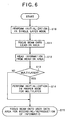
- the CPU 14 controls both of the laser power controller 15 and the servo controller 17. Through those controls, the initialization is carried out such that the laser power of the optical beam B and various gains (e.g., corresponding to a corrected position for a spherical aberration) are set to those values previously defined in a single layer mode (for the monolayer type of disk) (step S10).
- various gains e.g., corresponding to a corrected position for a spherical aberration
- the servo controller 17 drives the actuator 19 such that an optical beam B radiated from the pickup 11 is focused onto the lead-in area LA of the disk DK1 that has now been loaded (step S11).
- the focus error signal which can be collected by radiating the optical beam B to each information recording layer, shows the largest level when the beam is radiated toward the information recording layer L1 to be focused. That is, in the lead-in area LA, the optical beam B passes the information recording layers L2 and L4 without encountering any reflection layer until reaching the first information layer L1. The focus error signal detected at the information recording layers L2 to L4 becomes smaller than that at the first information recording layer L1.
- the optical pickup 11 reads out information from the lead-in area LA on the information recording layer L1 on which the optical beam B is focused, and gives a corresponding electrical signal indicative of the read information to the CPU 14 (step S12).
- the read-out information includes the number of information recording layers in the disk (i.e., the number of layers), the type of a media, a strategy pattern, an optimum laser power, and information in relation to copyright.
- the CPU 14 uses the read-out information to determine if or not the loaded disk is a multilayer type of disk (step S13).
- step S13 If it is determined at step S13 that the disk loaded at present is not a multilayer type (NO at step S 13), the disk is a monolayer type. In such a case, the recording or reproducing operation should be executed under the initial mode set at step S10. Hence, without switching the setting modes, the optical pickup 11 is allowed to perform, under the control of the CPU 11, a search operation in the user data area DA to start reading or reproducing information to be desired therein (step S15).
- the determination at step S 13 shows that the disk loaded at present is a multilayer type (YES at step S13), the CPU 14 performs control directed to the multilayer type of disk DK1. Namely, the CPU 14 sends commands to both the laser power controller 15 and the servo controller 17 to realize an optimum laser power to the optical beam B and a servo gain, which are appropriate for the recording or reproducing operation in or from the multilayer type of disk (step S14).
- the optical pickup 11 is allowed to perform, under the control of the CPU 11, a search operation in the user data area DA to start reading or reproducing information to be desired therein (step S15).
- the optical disk DK1 when the optical disk DK1 according to the present embodiment is loaded, the reflection layer exists in the only one information recording layer L1 in the lead-in area LA. It is therefore possible that the focus error signal, which is acquired when optical beam is radiated to each of the information recording layers, shows the largest level when the beam is radiated onto the only one information recording medium L1. In other words, the error focus signals detected from the remaining information recording layers L2 to L4 in the lead-in area LA becomes smaller compared to that detected from the layer L1, because there is no reflection layer in each of the layers L2 to L4. Accordingly, the optical beam B can reach an information recording layer to be targeted in a steady manner without erroneous detection.
- a time required for the optical pickup 11 to initialize the operation parameters can be shortened, because a time of period conventionally required for allowing the beam to reach an information recording layer to be targeted is omitted, in the case that the targeted information recording disk is far from the incidence surface.
- the lead-in area is provided with only one information recording layer having a reflection layer.
- the information recording and reproducing apparatus enables necessary information to be detected from an information recording layer to be targeted, because an optical beam can reach the targeted information recording layer in a quick manner without fail.
- the initialization is first set for the monolayer type of disk, and then the type of a disk is determined.
- the information-recording or -reproducing operation is started without changing the initialized parameters.
- the initialization for the multilayer type of disk is performed again.
- the multilayer type of disk is then subjected to recording or reproducing information.
- the distance from the beam incidence-side surface to the information recording layer L1 provided with the reflection layer is made to equal that of the monolayer type of optical disk in which only one information recording layer is provided.
- Fig. 7 shows a section of an optical disk employed by the second embodiment.
- This optical disk is identical to that described in the foregoing first embodiment except in that the optical disk is provided with adjustment layers BA serving as a dummy region between the lead-in area LA and the user data area DA.
- the adjustment layers BA are level individually with the information recording layers L located in the user data area DA.
- an information recording and reproducing apparatus according to the present embodiment which records or reproduces information in or from the optical disk shown in Fig. 7, is similar to that described in the first embodiment, so that the explanation will be omitted.
- the optical disk DK2 is provided with adjustment layers BA1 to BA4 formed as part of the individual information recording layers and located between the lead-in area LA and the user data area DA, the adjustment layers BA1 to BA4 being formed as being a region having a predetermined length.
- the adjustment layers BA1 to BA4 are the same in their reflection rates and transmission rates as those in the reflection layers in the user data area DA that is next to the adjustment layers.
- Arrangement of the adjustment layers causes both of face power on each layer and an amount of reflected light from each layer to be even over the layers, thus preventing inconveniences which may occur in the disk innermost circumferential portion.
- the centering error is about 70 ⁇ m in the case of the next-generation high-density DVD, it is preferred that the radial length of the adjustment layers is for example 100 ⁇ m or more.
- the explanation has been given to the optical disk provided with four information recording layers to form a multilayer type of disk, but this is not a definitive list.
- the foregoing layer structure in the lead-in area is applicable to an optical disk, as long as two or more information recording layers are provided therein.
- an optical disk with five information recording layers can also be provided, in which, in the lead-in area thereof, the reflection layer is formed in only the fifth information recording layer counted from the beam-incidence side. That is, provided that the reflection layer is provided by one in the lead-in area, the similar advantages to the above can be provided as well.
- the distance from the beam incidence-side surface to an information recording layer provided with a reflection layer therein in the lead-in area will not of course limited to an amount of 100 ⁇ m.
- optical beam is radiated to the multilayer type of optical disk from its substrate side, in place of having the optical beam radiated to the disk from its cover layer side for reading information.
- the present invention can also be reduced into practice to other recording mediums, such as tape-like recording medium, so long as an optical beam is used for the recording or reproduction.
Landscapes
- Optical Recording Or Reproduction (AREA)
- Optical Head (AREA)
- Optical Record Carriers And Manufacture Thereof (AREA)
Abstract
Description
Claims (14)
- A multilayer type of information recording medium (DK1, DK2), characterized in that the medium comprising:a plurality of information recording layers (L1 to L4) into each of which information is recordable; anda single corresponding-information recording layer (L1) into which information corresponding to the information recorded in the information recording layers is recordable.
- The multilayer type of information recording medium according to claim 1, characterized in that the corresponding information is control information for controlling either recording or reproduction of the information into and from each of the information recording layers.
- The multilayer type of information recording medium according to either claim 1 or 2, characterized in that the corresponding-information recording layer is provided with a reflection layer (RF1) to reflect an optical beam (B) radiated to optically read the corresponding information.
- The multilayer type of information recording medium according to claim 3, characterized in that a distance from a beam-incidence-side surface of the medium to the corresponding-information recording layer is the same as a distance from a beam-incidence-side surface of a monolayer type of information recording medium provided with a single information recording layer for recording the information to the single information recording layer.
- The multilayer type of information recording medium according to claim 4, characterized in that the distance from the beam-incidence-side surface of the medium to the corresponding-information recording layer is 100 µm.
- The multilayer type of information recording medium according to any one of claims 3 to 5, characterized in that the medium further comprising:a plurality of adjustment layers (BA1 to BA4) located between the single corresponding-information recording layer and the plurality of information recording layers and located continuously to the plurality of information recording layers, respectively, with the same level between each adjustment layer and the information recording layer kept.
- An information recording and reproducing apparatus (SP) for selectively recording or reproducing information into or from an information recording layer consisting of either a signal information recording layer of a monolayer type of information recording medium or one of a plurality of information recording layers (L1 to L4) of a multilayer type of information recording medium (DK1, DK2), characterized in that the apparatus comprising:a first setting device (14) configured to initialize operating parameters to be appropriate for either the recording or reproduction of the information into or from the information recording layer of the monolayer type of information recording medium;a determination device (14) configured to determine whether or not an information recording medium loaded currently in the information recording and reproducing apparatus is the monolayer type of information recording medium or the multilayer type of information recording medium, the determination being carried out after the initialization of the operating parameters;a first recording/ reproducing device (11) configured to start recording or reproducing the information into or from the information recording layer of the monolayer type of information recording medium on the basis of the initialized operating parameters, when the determination device determines that the currently loaded information recording medium is the monolayer type of information recording medium;a second setting device (14) configured to change the operating parameters to be appropriate for either the recording or reproduction of the information into or from the information recording layer of the multilayer type of information recording medium, when the determination device determines that the currently loaded information recording medium is the multilayer type of information recording medium; anda second recording/reproducing device (11) configured to start recording or reproducing the information into or from the information recording layer of the multilayer type of information recording medium on the basis of the changed operating parameters.
- The information recording and reproducing apparatus according to claim 7, characterized in that the multilayer type of information recording medium comprises a single corresponding-information recording layer (L1) into which information corresponding to the information recorded in the information recording layers is recordable.
- The information recording and reproducing apparatus according to claim 8, characterized in that the corresponding-information recording layer is provided with a reflection layer (RF1) to reflect an optical beam (B) radiated to optically read the corresponding information.
- The information recording and reproducing apparatus according to claim 9, characterized in that a distance from a beam-incidence-side surface of the medium to the corresponding-information recording layer is the same as a distance from a beam-incidence-side surface of a monolayer type of information recording medium provided with a single information recording layer for recording the information to the single information recording layer.
- The information recording and reproducing apparatus according to 10, characterized in that the distance from the beam-incidence-side surface of the medium to the corresponding-information recording layer is 100 µm.
- The information recording and reproducing apparatus according to claim 9, characterized in that the multilayer type of information recording medium further comprises a plurality of adjustment layers (BA1 to BA4) located between the single corresponding-information recording layer and the plurality of information recording layers and located continuously to the plurality of information recording layers, respectively, with the same level between each adjustment layer and the information recording layer kept.
- An information recording and reproducing method for selectively recording or reproducing information into or from an information recording layer consisting of either a signal information recording layer of a monolayer type of information recording medium or one of a plurality of information recording layers (L1 to L4) of a multilayer type of information recording medium (DK1, DK2), characterized in that the method comprising the steps of:initializing operating parameters to be appropriate for either the recording or reproduction of the information into or from the information recording layer of the monolayer type of information recording medium;determining whether or not an information recording medium loaded currently is the monolayer type of information recording medium or the multilayer type of information recording medium, the determination being carried out after the initialization of the operating parameters;first starting recording or reproducing the information into or from the information recording layer of the monolayer type of information recording medium on the basis of the initialized operating parameters, when it is determined that the currently loaded information recording medium is the monolayer type of information recording medium;changing the operating parameters to be appropriate for either the recording or reproduction of the information into or from the information recording layer of the multilayer type of information recording medium, when it is determined that the currently loaded information recording medium is the multilayer type of information recording medium; andsecond starting recording or reproducing the information into or from the information recording layer of the multilayer type of information recording medium on the basis of the changed operating parameters.
- A program enabling a computer to function for selectively recording or reproducing information into or from an information recording layer consisting of either a signal information recording layer of a monolayer type of information recording medium or one of a plurality of information recording layers (L1 to L4) of a multilayer type of information recording medium (DK1, DK2), characterized in that the computer providing the functions of:initializing operating parameters to be appropriate for either the recording or reproduction of the information into or from the information recording layer of the monolayer type of information recording medium;determining whether or not an information recording medium loaded currently is the monolayer type of information recording medium or the multilayer type of information recording medium, the determination being carried out after the initialization of the operating parameters;first starting recording or reproducing the information into or from the information recording layer of the monolayer type of information recording medium on the basis of the initialized operating parameters, when it is determined that the currently loaded information recording medium is the monolayer type of information recording medium;changing the operating parameters to be appropriate for either the recording or reproduction of the information into or from the information recording layer of the multilayer type of information recording medium, when it is determined that the currently loaded information recording medium is the multilayer type of information recording medium; andsecond starting recording or reproducing the information into or from the information recording layer of the multilayer type of information recording medium on the basis of the changed operating parameters.
Applications Claiming Priority (2)
| Application Number | Priority Date | Filing Date | Title |
|---|---|---|---|
| JP2002316057A JP2004152398A (en) | 2002-10-30 | 2002-10-30 | Multilayer information recording medium and multilayer information recording medium recording and reproducing apparatus |
| JP2002316057 | 2002-10-30 |
Publications (2)
| Publication Number | Publication Date |
|---|---|
| EP1416478A2 true EP1416478A2 (en) | 2004-05-06 |
| EP1416478A3 EP1416478A3 (en) | 2005-03-09 |
Family
ID=32089531
Family Applications (1)
| Application Number | Title | Priority Date | Filing Date |
|---|---|---|---|
| EP03256655A Withdrawn EP1416478A3 (en) | 2002-10-30 | 2003-10-22 | Multilayer type of information recording medium and information recording and reproducing apparatus using same |
Country Status (3)
| Country | Link |
|---|---|
| US (1) | US20050013225A1 (en) |
| EP (1) | EP1416478A3 (en) |
| JP (1) | JP2004152398A (en) |
Families Citing this family (7)
| Publication number | Priority date | Publication date | Assignee | Title |
|---|---|---|---|---|
| JP4315253B2 (en) * | 2004-02-03 | 2009-08-19 | パイオニア株式会社 | Information recording medium |
| JP2008059618A (en) * | 2005-01-07 | 2008-03-13 | Matsushita Electric Ind Co Ltd | Double-layer optical disc |
| CN100412957C (en) * | 2005-05-30 | 2008-08-20 | 松下电器产业株式会社 | Multilayer information recording medium and information device |
| JP2007323776A (en) * | 2006-06-02 | 2007-12-13 | Toshiba Corp | Optical recording medium, information recording method, and information reproducing method |
| TW200912910A (en) * | 2007-05-10 | 2009-03-16 | Koninkl Philips Electronics Nv | Disc startup time of an optical drive |
| US20100117827A1 (en) * | 2008-11-12 | 2010-05-13 | Mediatek Inc. | Method for current reduction for an analog circuit in a data read-out system |
| JP2010140576A (en) | 2008-12-15 | 2010-06-24 | Hitachi Ltd | Multilayer optical disk, and optical disk drive |
Family Cites Families (7)
| Publication number | Priority date | Publication date | Assignee | Title |
|---|---|---|---|---|
| JP3718941B2 (en) * | 1997-02-26 | 2005-11-24 | ソニー株式会社 | Optical disk device |
| JPH11195243A (en) * | 1997-12-26 | 1999-07-21 | Sony Corp | Multilayer optical disc and recording / reproducing device |
| CN1188842C (en) * | 1998-10-02 | 2005-02-09 | 索尼公司 | Device and method for replaying optical disk |
| WO2000057410A1 (en) * | 1999-03-23 | 2000-09-28 | Matsushita Electric Industrial Co., Ltd. | Rewritable multilayer disk and information recording / reproducing device |
| EP1111604A1 (en) * | 1999-06-28 | 2001-06-27 | Sony Corporation | Optical recording medium and method for reading optical recording medium |
| JP4300642B2 (en) * | 1999-08-18 | 2009-07-22 | ソニー株式会社 | Recording medium, recording medium reproducing apparatus and reproducing method |
| US6768710B2 (en) * | 2000-12-18 | 2004-07-27 | Matsushita Electric Industrial Co., Ltd. | Optical information recording medium, method for producing the same, and method and apparatus for recording information thereon |
-
2002
- 2002-10-30 JP JP2002316057A patent/JP2004152398A/en not_active Abandoned
-
2003
- 2003-10-22 EP EP03256655A patent/EP1416478A3/en not_active Withdrawn
- 2003-10-29 US US10/694,946 patent/US20050013225A1/en not_active Abandoned
Also Published As
| Publication number | Publication date |
|---|---|
| US20050013225A1 (en) | 2005-01-20 |
| EP1416478A3 (en) | 2005-03-09 |
| JP2004152398A (en) | 2004-05-27 |
Similar Documents
| Publication | Publication Date | Title |
|---|---|---|
| US7995429B2 (en) | Optical disk device and tilt correction method thereof | |
| US20110242948A1 (en) | Optical disc device and optical disc | |
| WO2005101381A1 (en) | Optical disc recording method and optical disc | |
| US7035185B2 (en) | Optical information recording apparatus, information processing apparatus, optical information recording medium, optical information recording method, and computer-readable storage medium | |
| EP1416478A2 (en) | Multilayer type of information recording medium and information recording and reproducing apparatus using same | |
| EP1517323B1 (en) | Optical disk apparatus and method for controlling the same | |
| US20050068873A1 (en) | Optical disc identification apparatus and method | |
| KR100430249B1 (en) | Apparatus for and method of determining information record medium | |
| EP1589529A2 (en) | Method for adjusting focus or tracking detection unit, and optical disc device | |
| US8335140B2 (en) | Optical disc drive for recording or reproducing data on a multilayer optical disc with a layer identification region | |
| CN101313358A (en) | Optical discs and optical disc devices | |
| US20060104176A1 (en) | Method of determining type of optical disc, and data recording and/or reproducing apparatus therefor | |
| JP2008524764A (en) | Calibration system optimization | |
| US7391683B2 (en) | Apparatus and method for detecting tilt of disc | |
| US7889606B2 (en) | Optical disc drive and control method thereof | |
| US7352666B2 (en) | Focus-balance calibration method | |
| US20050147001A1 (en) | Method or recording information, computer program, computer readable storage medium, and optical disk apparatus that stably record information on optical disk with high recording quality | |
| US9564167B2 (en) | Optical disc apparatus and control method thereof | |
| JP5380331B2 (en) | Optical disc, optical disc apparatus and reproducing method | |
| JP2006024246A (en) | Method for adjusting laser intensity of optical disc and optical disc recording / reproducing apparatus | |
| JPWO2006051688A1 (en) | Optical information recording / reproducing apparatus | |
| KR100718428B1 (en) | Tilt servo control method of optical disc | |
| EP1490869A1 (en) | Optical disc drive and method for controlling the same | |
| JP2006066063A (en) | Focus adjustment method in writing for optical disk drive | |
| US20070014216A1 (en) | Method of determining recording power and optical disc drive apparatus |
Legal Events
| Date | Code | Title | Description |
|---|---|---|---|
| PUAI | Public reference made under article 153(3) epc to a published international application that has entered the european phase |
Free format text: ORIGINAL CODE: 0009012 |
|
| AK | Designated contracting states |
Kind code of ref document: A2 Designated state(s): AT BE BG CH CY CZ DE DK EE ES FI FR GB GR HU IE IT LI LU MC NL PT RO SE SI SK TR |
|
| AX | Request for extension of the european patent |
Extension state: AL LT LV MK |
|
| PUAL | Search report despatched |
Free format text: ORIGINAL CODE: 0009013 |
|
| AK | Designated contracting states |
Kind code of ref document: A3 Designated state(s): AT BE BG CH CY CZ DE DK EE ES FI FR GB GR HU IE IT LI LU MC NL PT RO SE SI SK TR |
|
| AX | Request for extension of the european patent |
Extension state: AL LT LV MK |
|
| 17P | Request for examination filed |
Effective date: 20050307 |
|
| AKX | Designation fees paid |
Designated state(s): DE FR GB |
|
| STAA | Information on the status of an ep patent application or granted ep patent |
Free format text: STATUS: THE APPLICATION HAS BEEN WITHDRAWN |
|
| 18W | Application withdrawn |
Effective date: 20070723 |