FIELD OF THE INVENTION
1. Field of the Invention
This invention relates to a card processor for reading
card data recorded in a card such a magnetic card or an IC card
inserted in the insertion passage. More specifically, the
invention relates to a card processor with which a customer
inserts the card in the main body and pulls out or removes the
card from the main body by hand.
2. BACKGROUND OF THE INVENTION
There has heretofore been proposed a card processor for
reading card data recorded in a magnetic card or an IC card.
The card processor has been utilized in a variety of apparatuses
such as an automated teller machine (ATM) installed in banking
facilities.
Japanese patent publication JP-A-2001-167513 describes
a card processor of the manual type with which the customer
inserts the card through the insertion portion up to a set
position, and pulls out the card from the set position or removes
the card from the main body by hand.
In the magnetic card processor of the manual type, the
magnetic head is brought into contact with a magnetic stripe
of the card to read the card magnetic data recorded in the card
while the customer is inserting the card through the insertion
portion up to the set position or while the customer is removing
the card from the set position. In the manual IC card processor,
further, an IC contact is connected to an IC chip of the IC
card inserted up to the set position to thereby read the
electronic card data.
The insertion portion of the manual card processor is
formed in a recessed shape by being cut away in a direction
in which the card is inserted. Therefore, a rear end of the
card at the set position is exposed to the external side. This
permits the customer to pinch the rear end of the card by fingers
until the card is inserted up to the set position or until the
card is pulled out from the set position. The insertion passage
is equipped with a wall or a pin with which a leading end of
the card arrived at the set position comes in contact, so that
the card that has reached the set position will not be pushed
any more. The wall or pin works as a stopper for limiting the
length of insertion of the card.
However, the customers of the manual card processor are
encountering an increasing chances of unauthorized deed of
cheating the card in a manner as described below, and it has
been urged to develop a card processor which prevents the damage
due to such unauthorized deed.
SUMMARY OF THE INVENTION
It is an object of this invention to provide a card
processor capable of preventing the card from being stolen by
cheating by notifying the breakage of the stopper or card
processor or by executing an error processing such as inhibiting
the insertion of the card.
In order to achieve the above object, the card processor
of this invention is constituted as described below.
When the card is inserted by a predetermined length in
the insertion passage formed in the main body, the leading end
of the card comes in contact with the stopper member. Therefore,
if the stopper member has not beenbroken, the card is not inserted
in the main body in excess of a predetermined length.By forming the insertion passage in a manner that the
card which is in contact at its leading end with the stopper
member, is exposed at its rear end to the external side, the
customer can insert and take out or remove the card. The stopper
member may have any shape with which will come in contact the
leading end of the card that is inserted by, for example, a
predetermined length, and may be a wall formed in the direction
of width of the card or may be a plurality of pins arranged
in the direction of width of the card.The card may be, for example, a magnetic card, an IC card
or a composite card thereof. In the case of the magnetic card,
the magnetic head is brought into contact with the magnetic
stripe of the magnetic card to read the card data recorded therein
while the card is being inserted in the main body or is taken
out from the main body. In the case of the IC card, the terminal
portion on the side of the main body may be electrically connected
to an IC chip of the IC card inserted by a predetermined length
in the main body to read the card data.Further, the breakage detector detects any breakage of
the stopper. When the breakage of the stopper is detected,
the error processing is executed by the error processor. The
error processing executed by the error processor may be the
one for blocking the insertion passage by a shutter or the like
so that the card cannot be inserted in the main body, or may
be the one demonstrating the breakage of the stopper member
and producing an alarm sound so that the customer will not insert
the card in the main body.This prevents in advance the customer from inserting the
card in the main body without knowing the breakage of the stopper
member and, hence, prevents such an occurrence that the card
is inserted in the main body by more than a predetermined length
and is not taken out.
(2) The breakage detector can detect whether a
conductor/conducting-wire that runs along the stopper member
has been cut.
In this constitution, the conductor runs along the stopper
member, and the conductor is cut if the stopper member is broken.
Namely, whether the stopper member is broken is detected
depending upon whether the conductor is cut. (3) The stopper member can include a pawl portion formed at
a position between a light-emitting unit and a light-receiving
unit arranged facing each other, and the breakage detector means
detects whether the light-receiving unit is receiving light
emitted from the light-emitting unit.
In this constitution, if the stopper member is broken,
the pawl member moves from between the light-emitting unit and
the light-receiving unit that are arranged facing each other,
and light emitted from the light-emitting unit is received by
the light-receiving unit. Therefore, whether the stopper
member is broken is detected depending upon whether light emitted
from the light-emitting unit is received by the light-receiving
unit. (4) A card processor for reading card data recorded in a card
inserted in an insertion passage, wherein:
said insertion passage is provided with a stopper member
with which an end of the card comes in contact when it is inserted
in a main body by a predetermined length; and provision is made of:
a shielding member which is directly or indirectly
anchored to said stopper member, and shields the insertion
passage when the stopper member has been broken or is in a state
of not being anchored.
In this constitution, the insertion passage is shielded
when the shielding member which is directly or indirectly
anchored to the stopper member, is no longer anchored due to
the breakage of the stopper member. In case the stopper member
is broken, therefore, the customer is prevented from inserting
the card in the main body. Therefore, there is obtained the
same effect as the one obtained in (1) above.This constitution may be further furnished with:
- breakage detector for detecting the breakage of said
stopper member; and
- error processor for executing an error process when the
breakage of said stopper member is detected by said breakage
detector means,
like the constitution of (1) above.
(5) A card processor for reading card data recorded in a card
inserted in an insertion passage, wherein:
said insertion passage is provided with a stopper member
with which an end of the card comes in contact when it is inserted
in a main body by a predetermined length; and provision is made of:
breakage detector for detecting whether said stopper
member has been broken.
In this constitution, the breakage of the stopper member
may be notified to a host unit connected to the card processor.
Then, the host unit notifies the customer of the interruption
of service or the interruption of the card processing.
BRIEF DESCRIPTION OF THE DRAWINGS
Fig. 1 is a view illustrating a card processor according
to an embodiment of the invention.
Fig. 2 is a block diagram illustrating the functional
constitution of the card processor according to the embodiment
of the invention.
Fig. 3 is a flowchart illustrating the operation of the
card processor according to the embodiment of the invention.
Fig. 4 is a view illustrating the card processor according
to the embodiment of the invention.
Fig. 5 is a view illustrating a breakage detector unit
in the card processor according to the embodiment of the
invention.
Fig. 6 is a diagram illustrating the breakage detector
unit in the card processor according to the embodiment of the
invention.
Fig. 7 is a view illustrating the card processor according
to another embodiment.
Fig. 8 is a view illustrating the breakage detector unit
of the card processor according to a further embodiment.
Fig. 9 is a diagram illustrating the breakage detector
unit in the card processor according to a further embodiment.
Fig. 10 is a view illustrating the card processor according
to a further embodiment.
Fig. 11 is a view illustrating the cardprocessor according
to a further embodiment.
Fig. 12 is a view illustrating the cardprocessor according
to a still further embodiment.
Fig. 13 is a view illustrating the cardprocessor according
to a yet further embodiment.
DETAILED DESCRIPTION OF THE INVENTION
The card processor according to an embodiment of the
invention will now be described.
The card processor of this embodiment is used being
incorporated in the apparatus (hereinafter referred to as host
equipment) such as a cash dispensing machine (CD) , an automated
teller machine (ATM) and the like machine. Fig. 1 illustrates
the card processor of this embodiment. Fig. 1 (A) is a top view.
Fig. 1 (B) is a side view. Fig. 1 (C) is a sectional view along
the line A-A in Fig. 1 (A) . The card processor 1 is constituted
by overlapping an upper plate 2 and a lower plate 3 obtained
by molding a resin. Reference numeral 4 denotes a control
substrate. The control circuit substrate 4 is arranged over
the upper plate 2. The control circuit substrate 4 may be
arranged under the lower plate 3. An insertion passage 5 is
formed between the upper plate 2 and the lower plate 3 so that
a card 10 can be inserted therein.
In Fig. 1, an insertion portion is formed on the left
side for inserting the card 10. On the side of the insertion
portion, there are provided a shutter 11 for restricting the
insertion of the card 10 and a magnetic head 12. The shutter
11 is driven by a solenoid that is not shown in the drawing.
Further, a recessed portion 13 is formed on the side of the
insertion port. Reference numeral 14 denotes a connection
terminal that is electrically connected to an IC chip provided
in the card 10 that is inserted in the insertion passage 5.
A wall 6 is formed at an end on the side opposite to the insertion
portion of the insertion passage 5. The wall 6 corresponds
to a stopper member referred to in the invention.
The card 10 inserted in the insertion passage 5 through
the insertion portion comes in contact at its leading end with
the wall 6. Here, the length of the insertion passage 5 in
the direction of insertion (length from the insertion portion
to the wall 6) has been so determined that the rear end of the
card 10 (end on the side of the insertion port) is positioned
on the inside of the shutter 11 while a portion of the card
10 is exposed at the recessed portion 13. The area of the card
10 exposed at the recessed portion 13 is such that the card
can be easily pinched by fingers, enabling the customer to easily
insert and pull out or remove the card 10. The connection
terminal 14 is arranged at a position where it is electrically
connected to the IC chip of the card 10 that is in contact at
its leading end with the wall 6.
The height of the insertion passage 5 is slightly higher
than the height of the card 10. The control circuit substrate
4 is located in a housing of the host equipment in which the
card processor 1 is incorporated. The control circuit substrate
4 cannot be touched from the external side. The housing of
the host equipment is dented inward of the main body at a portion
where the recessedportion 13 is located, permittingthe customer
to easily insert and pull out the card 10. Further, rollers
which is not shown in the drawing can be arranged in the insertion
passage 5 so that the card 10 can be smoothly inserted and pulled
out.
A conductor 41 runs along the wall 6 and is secured at
two places on the upper surface of the upper plate 2 and on
the lower surface of the lower plate 3. An electric current
is flowing through the conductor 41 at all times. When the
wall 6 is broken, the conductor 41 is cut, and the interruption
of electric current is detected. Thus, the breakage of the
wall 6 is detected.
Fig. 2 is a block diagram illustrating the functional
constitution of the card processor 1 of this embodiment. A
control unit 20 controls the operation of the main body. A
first reader unit 21 reads the magnetic card data recorded in
the magnetic stripe of the card 10 inserted in the main body.
A second reader unit 22 reads electronic card data recorded
in the IC chip of the card inserted in the main body. A shutter
opening/closing unit 23 opens or closes the shutter 11 arranged
near the insertion portion of the card. An output unit 24 outputs ,
to the host equipment, the card data read by the first reading
unit 21 and by the second reading unit 22. A breakage detector
unit 25 detects the breakage of the wall 6 at the end opposing
the insertion port. The magnetic head 12 is connected to the
first reading unit 21, and the connection terminal 14 is
connected to the second reader unit 22. The shutter
opening/closing unit 23 drives the shutter 11 by using a solenoid
that is not shown in the drawing.
Described below is the operation of the card processor
1 according to the embodiment of the invention. The card 10
described here is a composite card being provided with the
magnetic stripe and the IC chip. The card may be provided with
either the magnetic stripe or the IC chip.
Fig. 3 is a flowchart illustrating the operation of the
card processor according to the embodiment. The card processor
1 is repetitively detecting whether the card 10 is inserted
through the insertion portion and whether the wall 6 at the
end facing the insertion port (wall 6 at the back of the insertion
passage 5) is broken (s1, s2). If the card 10 is inserted,
the card processor 1 executes a normal processing for reading
the card data from the card 10 that is inserted (s3) . If the
breakage of the wall 6 is detected (s4), the card processor
1 executes an error processing
First, described below with reference to Fig. 4 is the
operation (normal operation at s3 in the Fig. 3) in a state
where the wall 6 at the back of the insertion passage 5 has
not been broken (in a state of not being broken) . The customer
inserts the leading end of the card 10 in the insertion passage
5 through the insertion portion, and pushes the card 10 into
the main body (see Fig. 4 (A)) . At this moment, the insertion
portion has not been blocked with the shutter 11. The magnetic
stripe of the card 10 inserted in the insertion passage 5 by
the customer is brought into contact with the magnetic head
12. The card processor 1 reads the magnetic data recorded in
the magnetic stripe of the card 10.
When the leading end of the card 10 comes into contact
with the wall 6 on the side facing the insertion portion (see
Fig. 4(B)), the customer judges that the card 10 cannot be
inserted in the main body any more, and does not push the card
10 any more. At this moment, the rear end of the card 10 is
located in the main body inside of the shutter 11. Besides,
the magnetic head 12 is provided near the insertion portion
and can read all magnetic data recorded in the magnetic stripe
of the card 10. Further, the card 10 is partly exposed at the
recessed portion 13, and the customer is allowed to easily push
the card 10 until the leading end thereof comes in contact with
the wall 6.
In a state where the leading end of the card 10 is in
contact with the wall 6, the card processor 1 drives the shutter
11 to block the insertion portion, and electrically connects
the connection terminal 14 to the IC chip of the card 10 to
read the electronic data recorded in the IC chip of the card
10 or to record the electronic data therein (see Fig. 4(C)).
The shutter 11 may be driven and the connection terminal
may be electrically connected relying upon a detection by a
sensor that detects the contact of the leading end of the card
10 with the wall 6, or relying upon a mechanism that works when
the leading end 10 of the card 10 comes in contact with the
wall 6. The insertion portion is blocked with the shutter 11
in order to prevent the insertion of another card 10, and to
prevent the customer from inadvertently taking out (removing)
the card 10 from the main body while the data are being read
out from, or recorded into, the IC chip.
After the data processing for the IC chip is completed,
the card processor 1 drives the shutter 11 and opens the insertion
portion (returns back to the state of Fig. 4 (B) ) . The customer
takes out the card 10 from the main body of the card processor
1. At this moment, the customer pulls out the card 10 by pinching
a portion that is exposed in the recessed portion 13.
When the customer pulls out the card 10 from the main
body of the card processor 1, the magnetic data recorded in
the magnetic stripe of the card 10 can be read out.
The card processor 1 notifies the card data read out from
the card 10 to the host equipment through the output unit 24.
The host equipment carries out transaction processing based
on the card data notified from the card processor 1 or the input
operation by the customer who manipulates the operation unit
of the host equipment that is not shown in the drawing.
Described below is the constitution for detecting whether
the wall 6 on the side facing the insertion portion is broken.
Referring to Fig. 5, the card processor 1 of this embodiment
is such that a piece of conductor 41 is running along the wall
6 on the outer side of the insertion passage 5, the conductor
41 being connected at its both ends to the control circuit
substrate 4. Fig. 5(A) is a side sectional view of the rear
end (wall 6 side) of the card processor 1, and Fig. 5(B) is
a back view of the card processor. The conductor 41 is secured
at two places on the upper surface of the upper plate 2 and
on the lower surface of the lower plate 3. Referring to Fig.
6, the breakage detector unit 25 includes a pulse generator
circuit 42 connected to one end of the conductor 41 to generate
pulse signals, and a pulse detector circuit 43 connected to
the other end of the conductor 41 to detect pulse signals. The
pulse generator circuit 41 and the pulse detector circuit 42
are formed on the control circuit substrate 4.
The pulse generator circuit 42 in the breakage detector
unit 25 generates suitable pulse signals. When the above
suitable pulse signals are detected by the pulse detector circuit
43, it is so judged that the wall 6 is normal without being
broken. When the above suitable pulse signals have not been
detected by the pulse detector circuit 43, on the other hand,
it is so judged that the wall 6 is in an abnormal condition
in which it is broken.
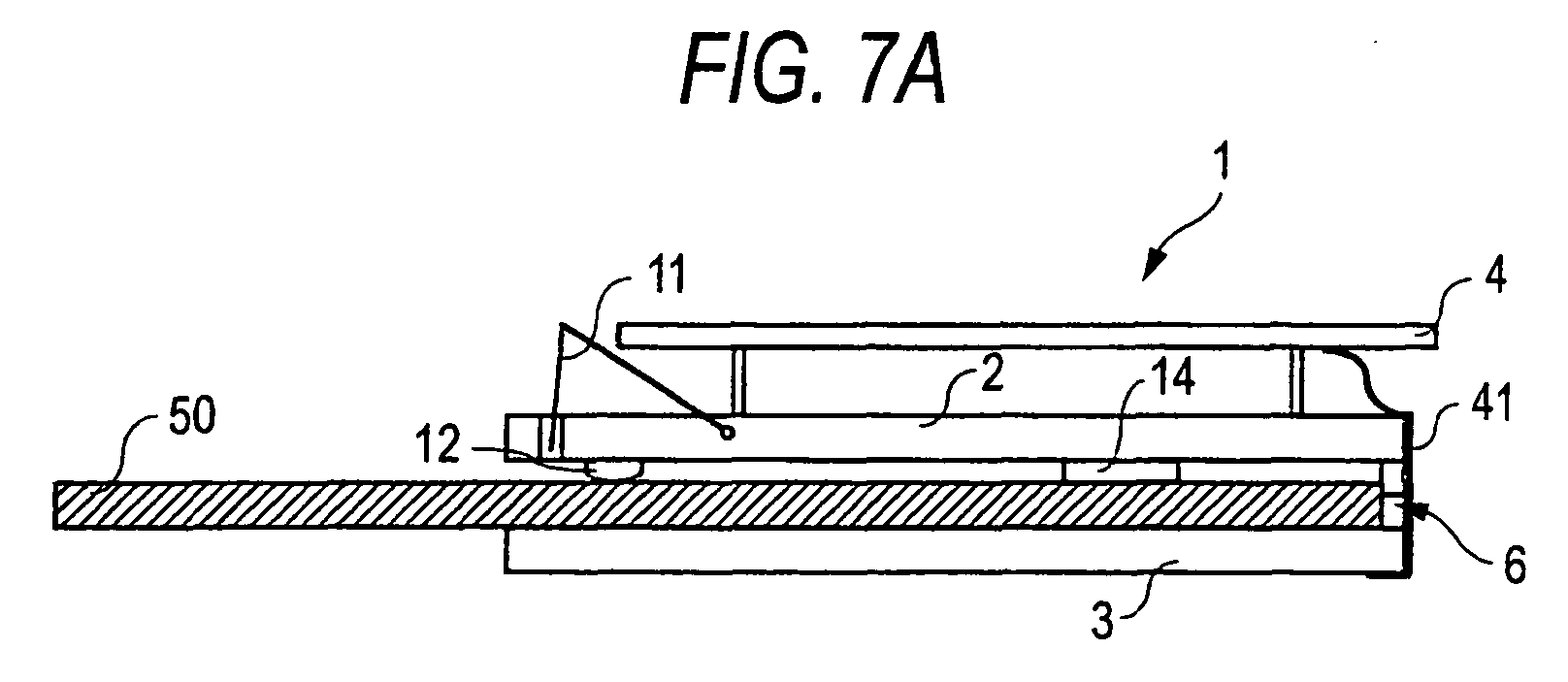
As described earlier, a thief who attempts to cheat the
customer's card 10 tries to insert a steel plate 50 through
the insertion portion as shown in Fig. 7 and further pushes
the steel plate 50 into the main body beyond a state were the
leading end of the steel plate 50 is in contact with the wall
6 (see Fig. 7 (A)) to break the wall 6 that is serving as a stopper
(see Fig. 7 (B)) . If the steel plate 50 is forcibly pushed into
the main body of the card processor 1 to break the wall 6, the
conductor 41 is cut due to the shock. Concretely speaking,
the conductor 41 is attached to the upper plate 2 and to the
lower plate 3. If the wall 6 is broken as shown in Fig. 7 (B) ,
therefore, the conductor 41 is cut being pushed by the wall
6 that is broken and by the steel plate 50. If the conductor
41 is cut, therefore, the pulse signals generated by the pulse
generator circuit are not detected by the pulse detector circuit
43, as a matter of course. Upon detecting the pulse signals
generated from the pulse generator circuit by the pulse detector
circuit 43, therefore, it is allowed to detect the breakage
of the wall 6 at the back of the insertion passage 5 facing
the insertion port.
Upon detecting the breakage of the wall 6, the card
processor 1 executes the error processing. The error
processing executed may be, for example, the one for requesting
the interruption of processing by the host equipment, the one
for blocking the insertion portion by driving the shutter 11
so that the card 10 cannot be inserted by the customer, the
one that displays the breakage of the wall 6 on a display portion
of the card processor 1 or of the host equipment and produces
an alarm sound letting the customer not to insert the card 10,
or the one which informs the center of the breakage of the wall
6 urging the replacement of the card processor 1. A plurality
of these processes may be executed in combination.
As soon as the breakage of the wall 6 is detected, the
error processing is readily executed to inform the center of
this fact, which may make it possible to catch the thief who
has broken the wall 6 while he is still removing the steel plate
50 from the cardprocessor 1, offering the effect for suppressing
the crime.
As the error processing, further, if the shutter 11 is
driven to block the insertion portion, the customer is reliably
prevented from inserting the card 10 in the insertion portion
of the card processor 1 of which the wall 6 that works as a
stopper has been broken. This reliably prevents such an
occurrence that the customer inserts the card 10 through the
insertion portion without knowing that the wall 6 has been broken,
pushes the card 10 until even a portion of the card 10 is not
exposed at the recessed portion 13, finds himself unable to
take out the card 10 that is pushed in, and goes for a clerk
in charge, and that the card 10 stolen by the thief who has
broken the wall 6.
In a state where the steel plate 50 is inserted in the
insertion passage 5, the insertion portion cannot be blocked
even by driving the shutter 11 (the end of the shutter comes
into a halt on the upper surface of the steel plate 50) . When
the steel plate 50 is removed from the insertion passage 5,
the insertion portion is blocked by the shutter 11.
The breakage detector unit 25 may be constituted in a
manner as described below.
Fig. 8 is a view illustrating another embodiment of the
breakage detector unit. Fig. 8(A) is a side sectional view
of the rear end (wall 6 side) of the card processor 1, and Fig.
8(B) is a back view of the card processor. In the breakage
detector unit 25, a pawl portion 51 is provided on the outer
side of the wall 6 that works as the stopper, and a light-emitting
unit 52 and a light-receiving unit 53 are opposed to each other
with the pawl portion 51 interposed therebetween. The breakage
detector unit 25 is provided, as shown in Fig. 9, with a
light-emitting circuit 55 for causing the light-emitting unit
52 to emit light and a light reception detector circuit 56 for
detecting whether the light from the light-emitting portion
52 has been received by the light-receiving unit 53. The
light-emitting unit 52 and the light-receiving unit 53 are
mounted on the control substrate 4. Further, the
light-emitting circuit 55 and the light reception detector
circuit 56 are mounted on the control substrate 4.
When the wall 6 at the back of the insertion passage 5
facing the insertion portion has not been broken, the pawl
portion 51 is located between the light-emitting unit 52 and
the light-receiving unit 53, and the light from the
light-emitting unit 52 is not received by the light-receiving
unit 53.
Referring to Fig. 10, the steel plate 50 is inserted
through the insertion portion, and is further pushed into the
main body beyond the state where the leading end of the steel
plate 50 is in contact with the wall 6 (see Fig. 10 (A)) to break
the wall 6 that works as the stopper (see Fig. 10 (B)). In the
card processor 1 of this embodiment, if the steel plate 50 is
forcibly pushed into the main body to break the wall 6, the
pawl portion 51 moves together with the wall 6 that is broken.
In the light-receiving unit 53, therefore, the light from the
light-emitting unit 52 is not shielded; i.e., the light from
the light-emitting unit 52 is received by the light-receiving
unit 53. Upon detecting whether the light from the
light-emitting unit 52 is received by the light-receiving unit
53 by using the light reception detector circuit 56, therefore,
it is allowed to detect the breakage of the wall 6 at the back
of the insertion passage 5 facing the insertion port.
The light-emitting unit 52 and the light-receiving unit
53 are mounted on the control substrate 4, and do not move together
with the broken wall 6. Besides, the electric connection
between the light-receiving unit 53 and the light reception
detector circuit 56 is not cut.
When the breakage of the wall 6 at the back of the insertion
passage 5 facing the insertion portion is detected, the above
error processing may be executed.
In the above embodiment, if the breakage of the wall 6
at the back of the insertion passage 5 facing the insertion
portion is detected by the breakage detector unit 25, the error
processing is executed to prevent the customer from inserting
the card 10 in the card processor 1. It is, however, also
allowable to provide the wall 6 with a shielding member that
is directly or indirectly anchored thereto, and to block the
insertion passage with the shielding member in case the wall
6 is broken and the anchored state is reset. In this case,
the breakage detector portion 25 is not required and the cost
can be decreased.
Described below is an embodiment of the card processor
provided with the shielding member.
Fig. 11 is a side sectional view of the card processor
of the embodiment.
In the drawing, the same constitutions as those of Fig.
1 are denoted by the same reference numerals but their
description is not repeated.
Referring to Fig. 11 (A) , a hook 61 is formed on the wall
6 , and one end (rear end) of a shieldingmember 62 that is swingably
attached is anchored to the hook 61. A fulcrum of the shielding
member 62 is located relatively close to the rear end, and a
swinging force is acting in a direction in which the front end
moves downward due to its own weight. Further, the front end
of the shielding member 62 is bent downward. Hereinafter, the
portion that is bent is referred to as folded portion 62a.
An opening 2a is formed in the upper plate 2 permitting
the folded portion 62a of the shielding member 62 to pass
therethrough. Further, a groove 3a is formed in the lower plate
3 permitting an end of the folded portion 62a to enter therein.
In a state where the wall 6 at the back of the insertion
passage 5 facing the insertion portion has not been broken,
the rear end of the shielding member 62 is anchored by the hook
61, and the end of the folded portion 62a of the shielding member
62 is not protruding into the insertion passage. In this state ,
therefore, the card 10 can be smoothly inserted through the
insertion port.
If the wall 6 at the back of the insertion passage 5 facing
the insertion portion is broken as shown in Fig. 11 (B) , on the
other hand, the hook 61 moves together with the broken wall
6, the rear end of the shielding member 62 is disengaged, and
the foldedportion 62a swings down. The endof the foldedportion
62a enters into the groove 3a formed in the lower plate 3.
Accordingly, the insertion passage 5 is shielded by the folded
portion 62a of the shieldingmember 62 , and even if it is attempted
to insert the card 10, the card is inserted only into a position
where the leading end of the card 10 comes in contact with the
folded portion 62a. This prevents such an occurrence that the
customer pushes the card 10 into the card processor 1 of which
the wall 6 at the back of the insertion passage 5 facing the
insertion portion has been broken, the card 10 being pushed
in to such a degree that the customer can no longer take it
out and falls in the hand of the thief.
When the rear end of the shielding member 62 is in a state
of not anchored, the shielding member 62 may be reliably turned
in the direction in which the front end moves down by being
urged by a resilient member such as a spring or a rubber.
Next, described below is a further embodiment. Referring
to Fig. 12, the card processor 1 of this embodiment has a carrier
passage constituted by three members including an upper plate
71, a lower plate 72 and a coupling portion 73. As shown in
Fig. 12, the coupling portion 73 is of a U-shape. Referring
to Fig. 12 (B) , the upper plate 71, lower plate 72 and coupling
portion 73 are assembled by insertion. At this moment, the
upper plate 71 and the lower plate 72 are adhered at contact
portions on both sides of the insertion passage 5. They, however,
are not adhered at portions where they are inserted in the
coupling portion 73. Further, a groove 72a is formed in the
lower plate 72. The upper plate 71 is shorter than the lower
plate 72 as shown.
As shown in Fig. 12 (C) , the control substrate 4 is secured
to the upper plate 71. Further, an opening is formed in the
control substrate 4, and a shielding member 75 is inserted in
the opening. The opening in the control substrate 4 is
positioned just on the groove 72a formed in the lower plate
72. The shielding member 75 is in a state of being placed on
the upper surface of the coupling member 73.
Here, as will be obvious from Fig. 12 (C) , the wall 6 at
the back of the insertion passage facing the insertion portion
is constituted by a coupling member. It can therefore be said
that the shielding member 75 is indirectly anchored to the wall
6.
As described above, if the steel plate is inserted through
the insertion portion to break the wall 6 at the back of the
insertion passage facing the insertion portion, the coupling
member 73 is removed from the upper plate 71 and the lower plate
72 as shown in Fig. 13, the shielding member 75 placed on the
coupling member 73 falls, and the lower end of the shielding
member 75 enters into the groove 72a of the lower plate 72.
At this moment, the upper end of the shielding member 75 is
positioned over the control substrate 4. Due to the opening
in the control substrate 75 and the groove 72a in the lower
plate 72, therefore, the shielding member 75 does not fall but
maintains its attitude.
The upper plate 71 is adhered to the lower plate 72 on
both sides of the insertion passage 5. As shown in Fig. 13,
therefore , the upper plate 71 does not fall even when the coupling
member 73 is removed from the upper plate 71 and the lower plate
72. Further, the control substrate 4 is mounted on the upper
plate 71, and does not fall.
In a state shown in Fig. 13, the insertion passage 5 is
shielded by the shielding member 75. Therefore, if it is
attempted to insert the card 10 through the insertion portion,
the card can be inserted only into a position where the leading
end of the card 10 comes in contact with the shielding member
75. Therefore, this prevents such an occurrence that the
customer pushes the card 10 into the card processor 1 of which
the wall 6 at the back of the insertion passage 5 facing the
insertion portion has been broken, the card 10 being pushed
in to such a degree that the customer can no longer take it
out and falls in the hand of the thief.
The above embodiments have dealt with the cases where
the wall 6 at the back of the insertion passage 5 facing the
insertion portion served as a stopper. As the stopper, however,
there can be employed any other constitution with which will
come in contact the leading end of the card 10 that is inserted
through the insertion portion preventing the card 10 from being
pushed in the main body any more, such as a plurality of pins
arranged in the direction of width of the insertion passage
5.
In the embodiments shown in Figs. 11 to 13, further, no
breakage detector unit 25 is employed. It is, however, also
allowable to provide the breakage detector unit 25 to readily
inform the center of the detection of the breakage.
Effect of the Invention:
According to the preferred embodiments of the invention
as described above, any attempt of the customer to insert the
card is prevented to prevent the customer's card from being
stolen in case the stopper member which limits the length of
insertion of the card in the main body has been broken.
While preferred embodiments of the invention have been
described and illustrated above, it should be understood that
these are exemplary of the invention and not to be considered
as limiting. Additions, deletions, substitutions, and other
modifications can be made without departing from the spirit
or scope of the present invention. Accordingly, the invention
is not to be considered as limited by the foregoing description
but is only limited by the scope of the appended claims.