EP1416267A1 - Micro chemical system, and method for light−heat conversion and spectral analysis performed by the system - Google Patents
Micro chemical system, and method for light−heat conversion and spectral analysis performed by the system Download PDFInfo
- Publication number
- EP1416267A1 EP1416267A1 EP02755658A EP02755658A EP1416267A1 EP 1416267 A1 EP1416267 A1 EP 1416267A1 EP 02755658 A EP02755658 A EP 02755658A EP 02755658 A EP02755658 A EP 02755658A EP 1416267 A1 EP1416267 A1 EP 1416267A1
- Authority
- EP
- European Patent Office
- Prior art keywords
- light
- detecting
- exciting light
- lens
- optical
- Prior art date
- Legal status (The legal status is an assumption and is not a legal conclusion. Google has not performed a legal analysis and makes no representation as to the accuracy of the status listed.)
- Withdrawn
Links
- 238000006243 chemical reaction Methods 0.000 title claims description 32
- 238000000034 method Methods 0.000 title claims description 25
- 239000000126 substance Substances 0.000 title description 3
- 238000010183 spectrum analysis Methods 0.000 title 1
- 230000003287 optical effect Effects 0.000 claims abstract description 105
- 239000007788 liquid Substances 0.000 claims abstract description 11
- 238000004458 analytical method Methods 0.000 claims abstract description 8
- 230000004075 alteration Effects 0.000 claims description 12
- 238000004611 spectroscopical analysis Methods 0.000 claims description 11
- 230000007246 mechanism Effects 0.000 claims description 5
- 230000001678 irradiating effect Effects 0.000 claims description 3
- 239000011521 glass Substances 0.000 description 32
- VYPSYNLAJGMNEJ-UHFFFAOYSA-N Silicium dioxide Chemical compound O=[Si]=O VYPSYNLAJGMNEJ-UHFFFAOYSA-N 0.000 description 31
- 239000000758 substrate Substances 0.000 description 19
- 229910052681 coesite Inorganic materials 0.000 description 15
- 229910052906 cristobalite Inorganic materials 0.000 description 15
- 239000000377 silicon dioxide Substances 0.000 description 15
- 229910052682 stishovite Inorganic materials 0.000 description 15
- 229910052905 tridymite Inorganic materials 0.000 description 15
- 230000000694 effects Effects 0.000 description 13
- 238000001514 detection method Methods 0.000 description 9
- 230000015572 biosynthetic process Effects 0.000 description 6
- 230000008859 change Effects 0.000 description 6
- 238000010276 construction Methods 0.000 description 6
- 230000007062 hydrolysis Effects 0.000 description 6
- 238000006460 hydrolysis reaction Methods 0.000 description 6
- 238000000926 separation method Methods 0.000 description 6
- 239000010419 fine particle Substances 0.000 description 5
- VXEGSRKPIUDPQT-UHFFFAOYSA-N 4-[4-(4-methoxyphenyl)piperazin-1-yl]aniline Chemical compound C1=CC(OC)=CC=C1N1CCN(C=2C=CC(N)=CC=2)CC1 VXEGSRKPIUDPQT-UHFFFAOYSA-N 0.000 description 4
- 238000005259 measurement Methods 0.000 description 4
- 239000005049 silicon tetrachloride Substances 0.000 description 4
- 238000005516 engineering process Methods 0.000 description 3
- 238000009792 diffusion process Methods 0.000 description 2
- 238000001962 electrophoresis Methods 0.000 description 2
- 238000005530 etching Methods 0.000 description 2
- 238000000605 extraction Methods 0.000 description 2
- 230000010354 integration Effects 0.000 description 2
- 238000005342 ion exchange Methods 0.000 description 2
- 238000002156 mixing Methods 0.000 description 2
- 102000039446 nucleic acids Human genes 0.000 description 2
- 108020004707 nucleic acids Proteins 0.000 description 2
- 150000007523 nucleic acids Chemical class 0.000 description 2
- 239000013307 optical fiber Substances 0.000 description 2
- 230000008569 process Effects 0.000 description 2
- 102000004169 proteins and genes Human genes 0.000 description 2
- 108090000623 proteins and genes Proteins 0.000 description 2
- IEXRMSFAVATTJX-UHFFFAOYSA-N tetrachlorogermane Chemical compound Cl[Ge](Cl)(Cl)Cl IEXRMSFAVATTJX-UHFFFAOYSA-N 0.000 description 2
- KKCBUQHMOMHUOY-UHFFFAOYSA-N Na2O Inorganic materials [O-2].[Na+].[Na+] KKCBUQHMOMHUOY-UHFFFAOYSA-N 0.000 description 1
- 238000002835 absorbance Methods 0.000 description 1
- 239000002253 acid Substances 0.000 description 1
- 239000003513 alkali Substances 0.000 description 1
- 239000005407 aluminoborosilicate glass Substances 0.000 description 1
- 230000005540 biological transmission Effects 0.000 description 1
- 239000005388 borosilicate glass Substances 0.000 description 1
- 230000007423 decrease Effects 0.000 description 1
- 238000006193 diazotization reaction Methods 0.000 description 1
- 230000007613 environmental effect Effects 0.000 description 1
- 229910052732 germanium Inorganic materials 0.000 description 1
- GNPVGFCGXDBREM-UHFFFAOYSA-N germanium atom Chemical compound [Ge] GNPVGFCGXDBREM-UHFFFAOYSA-N 0.000 description 1
- 238000010438 heat treatment Methods 0.000 description 1
- 230000006872 improvement Effects 0.000 description 1
- 239000000463 material Substances 0.000 description 1
- 238000006396 nitration reaction Methods 0.000 description 1
- 239000011368 organic material Substances 0.000 description 1
- 238000000206 photolithography Methods 0.000 description 1
- 229910001414 potassium ion Inorganic materials 0.000 description 1
- FGIUAXJPYTZDNR-UHFFFAOYSA-N potassium nitrate Chemical compound [K+].[O-][N+]([O-])=O FGIUAXJPYTZDNR-UHFFFAOYSA-N 0.000 description 1
- 239000005361 soda-lime glass Substances 0.000 description 1
- 229910001415 sodium ion Inorganic materials 0.000 description 1
- 239000007787 solid Substances 0.000 description 1
- 239000002904 solvent Substances 0.000 description 1
- 238000000638 solvent extraction Methods 0.000 description 1
- 125000006850 spacer group Chemical group 0.000 description 1
- 230000002194 synthesizing effect Effects 0.000 description 1
- 229910052716 thallium Inorganic materials 0.000 description 1
- -1 thallium ions Chemical class 0.000 description 1
- 238000011144 upstream manufacturing Methods 0.000 description 1
Images




Classifications
-
- G—PHYSICS
- G01—MEASURING; TESTING
- G01N—INVESTIGATING OR ANALYSING MATERIALS BY DETERMINING THEIR CHEMICAL OR PHYSICAL PROPERTIES
- G01N21/00—Investigating or analysing materials by the use of optical means, i.e. using sub-millimetre waves, infrared, visible or ultraviolet light
- G01N21/17—Systems in which incident light is modified in accordance with the properties of the material investigated
-
- G—PHYSICS
- G01—MEASURING; TESTING
- G01N—INVESTIGATING OR ANALYSING MATERIALS BY DETERMINING THEIR CHEMICAL OR PHYSICAL PROPERTIES
- G01N21/00—Investigating or analysing materials by the use of optical means, i.e. using sub-millimetre waves, infrared, visible or ultraviolet light
- G01N21/01—Arrangements or apparatus for facilitating the optical investigation
- G01N21/03—Cuvette constructions
- G01N21/05—Flow-through cuvettes
-
- G—PHYSICS
- G01—MEASURING; TESTING
- G01N—INVESTIGATING OR ANALYSING MATERIALS BY DETERMINING THEIR CHEMICAL OR PHYSICAL PROPERTIES
- G01N21/00—Investigating or analysing materials by the use of optical means, i.e. using sub-millimetre waves, infrared, visible or ultraviolet light
- G01N21/17—Systems in which incident light is modified in accordance with the properties of the material investigated
- G01N21/171—Systems in which incident light is modified in accordance with the properties of the material investigated with calorimetric detection, e.g. with thermal lens detection
-
- G—PHYSICS
- G01—MEASURING; TESTING
- G01N—INVESTIGATING OR ANALYSING MATERIALS BY DETERMINING THEIR CHEMICAL OR PHYSICAL PROPERTIES
- G01N21/00—Investigating or analysing materials by the use of optical means, i.e. using sub-millimetre waves, infrared, visible or ultraviolet light
- G01N21/01—Arrangements or apparatus for facilitating the optical investigation
- G01N21/03—Cuvette constructions
- G01N2021/0346—Capillary cells; Microcells
Definitions
- the present invention relates to a microchemical system and a photothermal conversion spectroscopic analysis method implemented by the system.
- microchemical systems that carry out mixing, reaction, separation, extraction, detection or the like on a sample placed in a very narrow channel which is formed in a small glass substrate or the like.
- reactions carried out in the microchemical systems include diazotization reactions, nitration reactions, and antigen-antibody reactions.
- extraction/separation include solvent extraction, electrophoretic separation, and column separation.
- Such a microsystem may use only a single function intended to carry out separation alone, or may use a plurality of functions in combination.
- an electrophoresis apparatus for analyzing extremely small amounts of proteins, nucleic acids or the like has been proposed (e.g. Japanese Laid-open Patent Publication (Kokai) No. 8-178897).
- This electrophoresis apparatus analyzes extremely small amounts of proteins, nucleic acids or the like and is provided with a channel-formed plate-shaped element comprised of two glass substrates joined together. Because the element is plate-shaped, breakage is less likely to occur than in the case of a glass capillary tube having a circular or rectangular cross section, and hence handling is easier.
- the temperature of a solvent is locally increased by thermal energy emitted due to light absorbed by a solute in the sample to cause a change in the refractive index and hence generate a thermal lens (photothermal conversion effect).
- the photothermal conversion spectroscopic analysis method utilizes this photothermal conversion effect.
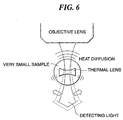
- FIG. 6 is a view useful in explaining the principle of a thermal lens.
- a convergent beam of exciting light is irradiated onto an extremely small sample via an objective lens of a microscope, whereupon the photothermal conversion effect takes place.
- the center of the convergent beam of exciting light is where the temperature rise is highest,, and hence the rise rate of the temperature is greater toward the center of the convergent beam of exciting light, whereas the rise rate of the temperature is smaller with increasing distance from the center of the convergent beam of exciting light due to thermal diffusion.
- the refractive index drops as the temperature rises, and hence the drop rate of the refractive index of the sample is greater toward the center of the convergent beam of exciting light, whereas the drop rate of the refractive index of the sample is smaller with increasing distance from the center of the convergent beam of exciting light.
- this pattern of change in the refractive index brings about the same effect as with a concave lens, and hence the effect is called the thermal lens effect.
- the size of the thermal lens effect i.e. the power of the thermal lens is proportional to the optical absorbance of the sample.
- a converse effect to the above i.e. the same effect as a convex lens is produced.
- thermal diffusion in a sample i.e. change in refractive index of the sample, is observed, and hence the method is suitable for detecting concentrations in extremely small amounts of samples.
- a photothermal conversion spectroscopic analyzer that uses the photothermal conversion spectroscopic analysis method described above has been proposed by Japanese Laid-open Patent Publication (Kokai) No. 10-232210.
- a channel-formed plate-shaped element is disposed below the objective lens of a microscope, and exciting light of a predetermined wavelength outputted from an exciting light source is introduced into the microscope.
- the exciting light is thus convergently irradiated via the objective lens onto a sample in the channel of the channel-formed plate-shaped element.
- a thermal lens is formed about the convergent irradiation position in which the exciting light is convergently irradiated.
- detecting light having a wavelength different to that of the exciting light is outputted from a detecting light source and also introduced into the microscope and then emitted therefrom.
- the detecting light emitted from the microscope is convergently irradiated onto the thermal lens that has been formed in the sample by the exciting light.
- the detecting light passing through the sample is either diverged or converged due to the effect of the thermal lens.
- the diverged or converged light exiting the sample passes as signal light through a converging lens and a filter or just a filter, and is then received and detected by a detector.
- the intensity of the detected signal light depends on the refractive index of the thermal lens formed in the sample.
- the detecting light may have the same wavelength as that of the exciting light, or the exciting light may be used as the detecting light as well.
- a thermal lens is thus formed at the focal position of the exciting light, and the change in refractive index within the formed thermal lens is detected by means of detecting light.
- the light source, measuring section and detecting section have complicated optical systems and hence are large in size and lacks portability.
- the photothermal conversion spectroscopic analyzer there are limitations on the place for installing the analyzer and the operation of the analyzer, and even the working efficiency of the user is degraded.
- the exciting light and the detecting light are guided in the air to the sample, and therefore, optical elements such as the light source, mirrors, and lenses are fixed to a solid surface table to prevent these optical elements from moving during measurement.
- optical elements such as the light source, mirrors, and lenses are fixed to a solid surface table to prevent these optical elements from moving during measurement.
- a jig is required for correcting the shifting.
- FIGS. 7A and 7B are views useful in explaining the formation position of the thermal lens and the focal position of the detecting light in the direction of travel of the exciting light.
- FIG. 7A shows a case in which the objective lens has chromatic aberration
- FIG. 7B shows a case in which the objective lens does not have chromatic aberration.
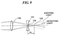
- a thermal lens 131 is formed at the focal position 132 of the exciting light as shown in FIG. 7A.
- the focal position 133 of the detecting light is shifted by an amount ⁇ L from the focal position 132 of the exciting light, and thus changes in the refractive index within the thermal lens 131 can be detected as changes in the focal distance of the detecting light from the detecting light.
- the focal position 133 of the detecting light is almost exactly the same as the position of the thermal lens 131 formed at the focal position 132 of the exciting light, as shown in FIG. 7B. The detecting light is thus not deflected by the thermal lens 131, and hence changes in the refractive index within the thermal lens 131 cannot be detected.
- the objective lens of a microscope is generally manufactured so as not to have chromatic aberration, and hence the focal position 133 of the detecting light is almost exactly the same as the position of the thermal lens 131 formed at the focal position 132 of the exciting light as described above, as shown in FIG. 7B. Changes in the refractive index within the thermal lens 131 thus cannot be detected. There is thus a problem that trouble must be taken to either shift the position in which the thermal lens 131 is formed from the focal position 133 of the detecting light every time a measurement is taken as shown in FIGS.
- a microchemical system comprising an exciting light source that outputs exciting light, a detecting light source that outputs detecting light, a guide optical system that guides the exciting light and the detecting light together, an irradiation lens that irradiates the exciting light and the detecting light guided by the guide optical system onto a sample, detecting means that detects the detecting light passing through a thermal lens generated by the sample on which the exciting light has been irradiated, and analysis means that analyses the sample based on the detected detecting light, characterized by comprising an optical unit in which the guide optical system and the irradiation lens are disposed, the optical unit having an optical wave guide path as an optical path of the guide optical system.
- the irradiation lens is fixed to an end of the optical wave guide path through which the exciting light and the detecting light are output.
- the detecting light has a different frequency from that of the exciting light, and the irradiation lens has a chromatic aberration.
- the irradiation lens comprises a gradient refractive index lens.
- the gradient refractive index lens is a solid-cylindrical rod lens.
- the optical wave guide path transmits the exciting light and the detecting light in a single mode.
- the optical unit has provided therein a light source for the exciting light and a light source for the detecting light.
- the optical unit has provided therein a channel disposed downstream of the irradiation lens in a direction of travel of the exciting light and the detecting light and through which a liquid containing the sample flows, and the detecting means disposed downstream of the channel in the direction of travel of the exciting light and the detecting light.
- the microchemical system comprises a channel-formed plate-shaped element disposed between the optical unit and the detecting means and having a channel through which a liquid containing the sample flows.
- the microchemical system comprises a parallel moving mechanism that moves the optical unit and the detecting means in parallel with a surface of the channel-formed plate-shaped element while maintaining relative positions of the optical unit and the detecting means.
- FIG. 1 is a schematic view showing the construction of a microchemical system according to a first embodiment of the present invention.
- the microchemical system 1 includes an optical unit 1a which is comprised of a plate-shaped element 10 in which various component parts are provided.
- the plate-shaped element 10 is provided therein with an optical wave guide path 20 formed as an optical path for exciting light and detecting light, described later, an irradiation lens 30 disposed at a downstream end of the optical wave guide path 20 in a direction of travel of the exciting light and detecting light, indicated by the arrow A, for irradiating the exciting light and detecting light onto a sample, and a channel 40 disposed downstream of the irradiation lens 30 in the direction indicated by the arrow A, and through which a liquid containing the sample flows.
- a detector 50 is disposed at an end of the plate-shaped element 10 downstream of the channel 40 in the direction indicated by the arrow A.
- the optical wave guide path 20 is designed to transmit light in a single mode as the sole transmission mode.
- the microchemical system 1 is further comprised of an exciting light source 61 such as a laser diode, that outputs the exciting light, a modulator 62 that modulates the exciting light, a detecting light source 63 such as a laser diode, that outputs the detecting light, an optical multiplexer 64 that coaxially aligns the exciting light and the detecting light, a lock-in amplifier 70 that synchronizes a detection signal received by the detector 50 with the modulator 62, and a computer 71 that analyzes an output signal from the lock-in amplifier 70.
- the exciting light and the detecting light that are aligned with each other by the optical multiplexer 46 are guided in the single mode by the optical wave guide path 20 to the irradiation lens 30.
- the optical wave guide path 20 is of the single mode type is that in the case where a very small amount of solute in a sample is detected using the photothermal conversion spectroscopic analysis method, it is desirable that the exciting light should be as small as possible to obtain a great amount of energy used for the photothermal conversion, and a thermal lens having a small aberration should be generated by the exciting light.
- the exciting light used to generate the thermal lens should desirably have a Gaussian distribution. Since light output from an optical fiber of the single mode type always has a Gaussian distribution, such an optical fiber is suitable for making the focal point of the exciting light small. If the thermal lens generated by the exciting light is small in size, it is desirable that the detecting light should also be limited to as small in diameter as possible to increase the number of detecting light beams passing the thermal lens to the maximum possible number. To this end, it is preferable that the exciting light and the detecting light are transmitted in the single mode.
- the plate-shaped element 10 is comprised of glass substrates 11, 12 and 13 which are stacked upon one another in three layers.
- the plate-shaped element 10 is preferably made of glass in terms of durability and chemical resistance.
- the material is preferably a glass that has excellent acid resistance and alkali resistance, for example a borosilicate glass, a soda lime glass, an aluminoborosilicate glass, a quartz glass or the like.
- the plate-shaped element 20 may be made of an organic material such as a plastic for some specific usage.
- the intermediate glass substrate 12 is formed therein with the channel 40 through which flows a liquid containing a sample for mixing, agitating, synthesizing, separating, extracting or detecting the sample.
- the intermediate glass substrate 12 is formed therein with the optical wave guide path 20.
- the method for forming the optical wave guide path 20 is not limitative, and a flame hydrolysis method may be used, for example.
- FIG. 2 is a view useful in explaining steps of forming an optical wave guide path by the flame hydrolysis method.
- silicon tetrachloride SiCl 4
- SiCl 4 silicon tetrachloride
- a flame hydrolysis process to deposit a glass fine particle layer formed of SiO 2 for a clad on a surface of the glass substrate 12, and then the glass fine particle layer is heated to a high temperature to form a SiO 2 layer 12a.
- a flame hydrolysis process is carried on silicon tetrachloride (SiCl 4 ) and germanium tetrachloride (GeCl 4 ) to deposit a glass fine particle layer formed of SiO 2 in which germanium (Ge) is doped on a surface of the SiO 2 layer 12a, and the glass fine particle layer is heated to a high temperature to form a Ge-doped SiO 2 layer 12b for a core.
- a portion of a surface of the Ge-doped SiO 2 layer 12b which is to be left as a core is covered with a mask m.
- a glass fine particle layer formed of SiO 2 is again deposited, followed by heating to a high temperature to form a SiO 2 layer 12c.
- a clad of the SiO 2 layers 12a, 12c and a core of the Ge-doped SiO 2 layer 12b surrounded by the clad are formed.
- the Ge-doped SiO 2 layer 12b has a higher refractive index than those of the surrounding SiO 2 layers 12a, 12c.
- an optical wave guide path is formed by the clad and the core.
- the formation of the SiO 2 layer for the clad may be omitted.
- the optical guide path 20 is formed in cbncentricity with a central line passing the centers of the irradiation lens 30 and the channel 40. Therefore, the portion of the glass substrate 12 in which the optical wave guide path 20 is to be formed may be removed to a suitable depth in advance by etching or the like, followed by forming the optical wave guide path 20 by the flame hydrolysis method.
- the optical multiplexer 64 is connected to an end of the optical wave guide path 20 formed as above opposite to the end on the side of the irradiation lens 30.
- the exciting light source 61 and the detecting light source 63 are connected to the optical multiplexer 64.
- the modulator 62 is connected to the exciting light source 61. It may be arranged such that the exciting light and the detecting light are coaxially aligned with each other outside the optical wave guide path by a dichroic mirror or the like instead of using the optical multiplexer 64, before they are input to the optical wave guide path 20.
- the end of the optical wave guide 20 on the irradiation lens 30 side reaches an irradiation lens housing 31 formed for accommodating the irradiation lens 30.
- the irradiation lens 30 accommodated in the irradiation lens housing 31 is a gradient refractive index rod lens.
- the irradiation lens 30 will be also hereinafter referred to as the rod lens 30.
- the rod lens 30 may be manufactured, for example, by the following method.
- a rod-shaped element is formed from a glass having 57 to 63 mol% of SiO 2 , 17 to 23 mol% of B 2 O 3 , 5 to 17 mol% of Na 2 O, and 3 to 15 mol% of Tl 2 O as principal components.
- This glass rod element is then treated in an ion exchange medium such as a potassium nitrate salt bath, thus carrying out ion exchange between thallium ions and sodium ions in the glass and potassium ions in the medium, and hence generates in the glass rod element a refractive index distribution in which the refractive index decreases continuously from the center of the glass rod element toward the periphery thereof.
- the rod lens 30 accommodated in the irradiation lens housing 31 is designed such that the focal position of the detecting light is shifted slightly by an amount ⁇ L relative to the focal position of the exciting light.
- the numeral aperture of output light of the optical wave guide path 20 is small, and therefore, if a rod lens having a large numerical aperture is used, calculations must be carried out using the numerical aperture of the optical wave guide path 20.
- the ⁇ L value described above varies according to the thickness of the sample to be analyzed.
- ⁇ L represents the difference between the focal position of the detecting light and the focal position of the exciting light, and the same result is achieved regardless of whether the focal distance of the detecting light is longer or shorter than the focal distance of the exciting light.
- the exciting light and the detecting light having passed through the rod lens 30 are irradiated onto a sample in the channel 40. Part of the exciting light that is irradiated is absorbed by the sample. The sample that has absorbed the exciting light rises in temperature to produce a thermal lens effect. The exciting light and the detecting light that have passed through the sample having produced the thermal lens effect are detected by the detector 50 disposed at the end of the plate-shaped element 10.
- the detector 50 is mounted in the end of the plate-shaped element 10, and is comprised of a wavelength filter 51 close to the channel 40, and a photoelectric transducer 52 disposed in series to the wavelength filter 51.
- the wavelength filter 51 selectively allows only the detecting light, out of the exciting light and the detecting light that have passed through the thermal lens generated by the sample, to pass therethrough.
- a pin hole for passing only part of the detecting light may be provided upstream of the photoelectric transducer 52 in the direction indicated by the arrow A.
- a detection signal obtained through detection of the detecting light by the photoelectric transducer 52 is delivered to the lock-in amplifier 72 for synchronizing the detection signal with the modulator 62. Then, the delivered detection signal is analyzed by the computer 71.
- the detector 50 may be disposed within the plate-shaped element 10 or may be mounted in the end face of the plate-shaped element 10.
- the optical multiplexer 64, exciting light source 61, modulator 62 and detecting light source 63 may be formed in one body with the plate-shaped element 10, whereby the microchemical system 1 can be made compact in size.
- FIG. 4 is a schematic view showing the construction of a microchemical system according to a second embodiment of the present invention.
- the microchemical system 2 according to the present embodiment includes an exciting light source 61, a detecting light source 63, and others, and further includes an optical unit 2a which is comprised of a plate-shaped element 80 having an optical wave guide path 20 formed therein.
- a gradient refractive index rod lens 30 has an end face thereof disposed in contact with a surface of the prism 81 through which the exciting light and the detecting light having changed in traveling direction are output.
- the other end face 30a of the rod lens 30 extends parallel with a major surface 80a of the plate-shaped element 80.
- the end face 30a of the rod lens 30 may be flush with the major surface 80a of the plate-shaped element 80.
- a channel corresponding to the channel 40 of the microchemical system according to the second embodiment is not formed in the plate-shaped element 80. Instead, a channel through which a liquid containing a sample flows is formed in a channel-formed plate-shaped element 110 which is a separate member from the plate-shaped element 80.
- the channel-formed plate-shaped element 110 is comprised of three glass substrates 111, 112, and 113 stacked one upon another, with the intermediate glass substrate 112 having a channel 140 formed therein.
- the channel-formed plate-shaped element 110 and the plate-shaped element 80 extend parallel with each other.
- the focal position of the exciting light output from the rod lens 30 lies within the channel 140.
- the end face 30a of the rod lens 30 from which the exciting light is output may be disposed in contact with the opposed surface of the channel-formed plate-shaped element 110 (the surface 111a of the glass substrate 111) or may be spaced therefrom.
- a glass substrate 111 having a thickness suitable for the focal distance of the rod lens 30 may be used such that the focal position of the rod lens 30 can be located within the channel 140. If the glass substrate 111 has an insufficient thickness, a spacer for adjustment of the focal distance may be interposed between the rod lens 30 and the glass substrate 111. These methods do not require an operation of adjusting the focal distance, to thereby contribute to improvement of the working efficiency of the user. Besides, a device for adjusting the focal distance is not required, thereby making it possible to design the microchemical system compact in size and reduce the cost.
- the exciting light and the detecting light output from the rod lens 30 pass through the sample in the channel 140 and are then detected by the detector 50 disposed below the channel-formed plate-shaped element 110.
- a detection signal is output from the detector 50 and passes through the lock-in amplifier 70 to be analyzed by the computer 71.
- FIG. 5 is a schematic view showing the construction of a microchemical system according to a third embodiment of the present invention.
- the microchemical system 3 according to the present embodiment includes an exciting light source 61, a detecting light source 63, and others, and further includes an optical unit 3a which is comprised of a plate-shaped element 90 having an optical wave guide path 20 formed therein.
- a gradient refractive index rod lens 30 which is disposed with its optical axis in alignment with the direction in which the optical wave guide path 20 extends.
- the plate-shaped element 90 is disposed such that the end thereof on which the gradient refractive rod lens is mounted is located downward.
- the rod lens 30 may have one end thereof disposed in contact with a downstream end of the optical wave guide path 20 that guides the exciting light and the detecting light.
- the rod lens 30 may be housed in the plate-shaped element 90.
- a plate-shaped element 210 is disposed below the rod lens 30.
- the rod lens 30 and the plate-shaped element 210 are disposed such that an end face of the rod lens 30 and an opposed surface of the plate-shaped element 210 extend parallel with each other.
- the plate-shaped element 210 is formed therein with a plurality of channels 240 through which a liquid containing a sample flows.
- the plate-shaped element 210 is comprised of three glass substrates 211, 212 and 213 stacked one upon another, with the channels 240 formed in the intermediate glass substrate 212.
- An XY stage (parallel moving mechanism) having a stage 250 is disposed parallel with the other surface of the channel-formed plate-shaped element 210.
- the stage 250 has mounted thereon a carrier 260 which is guided to move parallel with the channel-formed plate-shaped element 210.
- Fixed to the carrier 260 is a jig 261 which crosses the stage 250 and extends in a direction perpendicular to the channel-formed plate-shaped element 210.
- the jig 261 has an upper end thereof located above the channel-formed plate-shaped element 210 and a lower end below the same.
- the plate-shaped element 90 is secured to the upper end of the jig 261, and a detector 50 which has a light receiving portion, not shown, directed toward the plate-shaped element 210 is secured to the lower end of the jig 261.
- the rod lens 30 and the detector 50 move parallel with the respective opposed surfaces of the channel-formed plate-shaped element 210 while maintaining respective relative positions.
- thee rod lens 30 and the detector 50 By causing thee rod lens 30 and the detector 50 to move by this XY stage, it is possible to measure the sample in the channels 240 formed in the plate-shaped element 210 at desired measuring points.
- the exciting light and the detecting light are guided in a single mode to the irradiation lens via an optical wave guide path. Therefore, the exciting light and the detecting light can be always maintained in coaxially aligned relation. As a result, it is not necessary to adjust the optical axes of the exciting light and the detecting light relative to each other, to thereby enable the working efficiency of the user to be improved.
- an optical unit in which the guide optical system and the irradiation lens are disposed, the optical unit having an optical wave guide path as an optical path of the guide optical system. Therefore, the exciting light and the detecting light can be always maintained in coaxially aligned relation. As a result, it is not necessary to adjust the optical axes of the exciting light and the detecting light relative to each other, to thereby enable the working efficiency of the user to be improved. Further, since a device for optical axis adjustment is not required, the microchemical system can be designed compact in size.
- the irradiation lens is fixed to an end of the optical wave guide path through which the exciting light and the detecting light are output. Therefore, the optical axes of all of the exciting light and the detecting light as well as the irradiation lens can be fixed in position. As a result, the optical axis adjustment is not required, enabling the working efficiency of the user to be positively improved. Further, since a jig for optical axis adjustment or the like is not required, the microchemical system can be positively designed compact in size.
- the detecting light has a different frequency from that of the exciting light, and the irradiation lens has a chromatic aberration.
- the focal positions of the exciting light and the detecting light can be shifted without using an external optical system, to thereby enable the microchemical system to be designed more compact in size.
- the irradiation lens comprises a gradient refractive index lens. Therefore, the irradiation lens can be made smaller in size. This leads to the possibility that the microchemical system is designed more compact in size.
- the gradient refractive index lens is a solid-cylindrical rod lens. As a result, it is easy to carry the gradient refractive index lens.
- the optical wave guide path transmits the exciting light and the detecting light in a single mode. Therefore, the thermal lens generated by the exciting light can have a reduced aberration. As a result, measurements can be achieved with higher accuracy.
- the optical unit has provided therein a light source for the exciting light and a light source for the detecting light. Therefore, it is not necessary to provide a space for installing the exciting light source and the detecting light source outside the optical unit, to thereby ensure that the microchemical system can be designed more compact in size.
- the optical unit has provided therein a channel through which a liquid containing the sample flows, and the detecting means. It is, therefore, not necessary to provide a space for installing a channel-formed element and the detecting means outside the optical unit, to thereby ensure that the microchemical system can be designed more compact in size.
- the microchemical system comprises a channel-formed plate-shaped element disposed between the optical unit and the detecting means and having a channel through which a liquid containing the sample flows. This can facilitate replacement of the channel-formed plate-shaped element with a new one.
- a parallel moving mechanism can move the optical unit and the detecting means in parallel with a surface of the channel-formed plate-shaped element while maintaining relative positions of the optical unit and the detecting means. This can dispense with the need to move the channel-formed plate-shaped element when changing the measuring position. As a result, the user need not wait for any time period until the sample in the channel becomes stationary if the channel-formed plate-shaped element were moved, to thereby enable the measure to be carried out quickly. This leads to further enhanced working efficiency of the user. Further, since the relative positions of the optical unit and the detecting means are maintained, no mechanism for adjusting the relative positions is required, to thereby ensure that the microchemical system can be designed more compact in size.
Landscapes
- Physics & Mathematics (AREA)
- Health & Medical Sciences (AREA)
- Life Sciences & Earth Sciences (AREA)
- Chemical & Material Sciences (AREA)
- Analytical Chemistry (AREA)
- Biochemistry (AREA)
- General Health & Medical Sciences (AREA)
- General Physics & Mathematics (AREA)
- Immunology (AREA)
- Pathology (AREA)
- Investigating Or Analyzing Materials Using Thermal Means (AREA)
- Investigating Or Analysing Materials By Optical Means (AREA)
Abstract
Description
Claims (11)
- A photothermal conversion spectroscopic analysis method of analyzing a sample by irradiating exciting light and detecting light via an irradiation lens, and detecting the detecting light passing through a thermal lens generated by the sample onto which the exciting light has been irradiated, characterized in that the exciting light and the detecting light are guided in a single mode to the irradiation lens via an optical wave guide path.
- A microchemical system comprising an exciting light source that outputs exciting light, a detecting light source that outputs detecting light, a guide optical system that guides the exciting light and the detecting light together, an irradiation lens that irradiates the exciting light and the detecting light guided by said guide optical system onto a sample, detecting means that detects the detecting light passing through a thermal lens generated by the sample on which the exciting light has been irradiated, and analysis means that analyses the sample based on the detected detecting light, characterized by comprising an optical unit in which said guide optical system and said irradiation lens are disposed, said optical unit having an optical wave guide path as an optical path of said guide optical system.
- A microchemical system as claimed in claim 2, wherein the irradiation lens is fixed to an end of the optical wave guide path through which the exciting light and the detecting light are output.
- A microchemical system as claimed in claim 2 or 3, wherein the detecting light has a different frequency from that of the exciting light, and said irradiation lens has a chromatic aberration.
- A microchemical system as claimed in any of claims 2 to 4, wherein said irradiation lens comprises a gradient refractive index lens.
- A microchemical system as claimed in claim 5, wherein said gradient refractive index lens is a solid-cylindrical rod lens.
- A microchemical system as claimed in any of claims 2 to 6, wherein the optical wave guide path transmits the exciting light and the detecting light in a single mode.
- A microchemical system as claimed in any of claims 2 to 7, wherein said optical unit has provided therein a light source for the exciting light and a light source for the detecting light.
- A microchemical system as claimed in any of claims 2 to 8, wherein said optical unit has provided therein a channel disposed downstream of said irradiation lens in a direction of travel of the exciting light and the detecting light and through which a liquid containing the sample flows, and said detecting means disposed downstream of the channel in the direction of travel of the exciting light and the detecting light.
- A microchemical system as claimed in any of claims 2 to 8, comprising a channel-formed plate-shaped element disposed between the optical unit and the detecting means and having a channel through which a liquid containing the sample flows.
- A microchemical system as claimed in claim 10, comprising a parallel moving mechanism that moves said optical unit and said detecting means in parallel with a surface of said channel-formed plate-shaped element while maintaining relative positions of said optical unit and said detecting means.
Applications Claiming Priority (3)
| Application Number | Priority Date | Filing Date | Title |
|---|---|---|---|
| JP2001227713A JP2003042982A (en) | 2001-07-27 | 2001-07-27 | Photothermal conversion spectroscopy method and microchemical system for performing the method |
| JP2001227713 | 2001-07-27 | ||
| PCT/JP2002/007552 WO2003010527A1 (en) | 2001-07-27 | 2002-07-25 | Micro chemical system, and method for light-heat conversion and spectral analysis performed by the system |
Publications (1)
| Publication Number | Publication Date |
|---|---|
| EP1416267A1 true EP1416267A1 (en) | 2004-05-06 |
Family
ID=19060335
Family Applications (1)
| Application Number | Title | Priority Date | Filing Date |
|---|---|---|---|
| EP02755658A Withdrawn EP1416267A1 (en) | 2001-07-27 | 2002-07-25 | Micro chemical system, and method for light−heat conversion and spectral analysis performed by the system |
Country Status (6)
| Country | Link |
|---|---|
| US (1) | US7092099B2 (en) |
| EP (1) | EP1416267A1 (en) |
| JP (1) | JP2003042982A (en) |
| CN (1) | CN1549922A (en) |
| RU (1) | RU2004104626A (en) |
| WO (1) | WO2003010527A1 (en) |
Families Citing this family (6)
| Publication number | Priority date | Publication date | Assignee | Title |
|---|---|---|---|---|
| JP3848125B2 (en) | 2001-10-22 | 2006-11-22 | 日本板硝子株式会社 | Photothermal conversion spectroscopic analysis method and microchemical system |
| JP3824224B2 (en) * | 2002-09-27 | 2006-09-20 | 日本板硝子株式会社 | Micro chemical system |
| JP2005331407A (en) * | 2004-05-20 | 2005-12-02 | Nippon Sheet Glass Co Ltd | Photothermal conversion spectral analyzing method and microchemical system for performing the same |
| US8354069B2 (en) | 2005-03-08 | 2013-01-15 | Authentix, Inc. | Plug flow system for identification and authentication of markers |
| CN103454216B (en) * | 2013-09-07 | 2015-06-17 | 齐鲁工业大学 | Method and system for calibrating measurement resolution of runner-type pulp fiber measuring system on line |
| JP7229084B2 (en) * | 2019-04-19 | 2023-02-27 | 株式会社 堀場アドバンスドテクノ | optical analyzer |
Family Cites Families (12)
| Publication number | Priority date | Publication date | Assignee | Title |
|---|---|---|---|---|
| DE427943C (en) * | 1925-02-03 | 1926-04-19 | Benninger Ag Maschf | Curved spreader rollers with spreader bodies |
| GB8621426D0 (en) * | 1986-09-05 | 1986-10-15 | Health Lab Service Board | Particle analysis |
| US4938593A (en) * | 1987-01-30 | 1990-07-03 | The Regents Of The University Of Michigan | Photothermal densitometer for reading electrophoresis gels |
| DE4231214C2 (en) * | 1992-09-18 | 1994-12-08 | Kernforschungsz Karlsruhe | Photothermal sensor |
| JP2790067B2 (en) | 1994-12-27 | 1998-08-27 | 株式会社島津製作所 | Electrophoresis device |
| JP3124465B2 (en) | 1995-01-13 | 2001-01-15 | 株式会社精工技研 | Optical coupler |
| JPH10232210A (en) | 1997-02-19 | 1998-09-02 | Bunshi Bio Photonics Kenkyusho:Kk | Photothermal conversion spectrometer |
| US6452710B1 (en) * | 1997-08-08 | 2002-09-17 | National Institute Of Advanced Industrial Science And Technology | Optical element, optical control method and device using this optical element, and method of manufacturing optical element |
| KR20010052741A (en) | 1998-06-12 | 2001-06-25 | 야마모토 카즈모토 | Analyzer |
| JP2000002677A (en) | 1998-06-15 | 2000-01-07 | Asahi Chem Ind Co Ltd | Analysis equipment |
| JP4086173B2 (en) * | 1999-08-25 | 2008-05-14 | 学校法人大阪産業大学 | Photothermal lens type sample analyzer |
| EP1251348A4 (en) * | 2000-01-28 | 2005-01-12 | Asahi Chemical Ind | Photothermic transducing spectroscopic analyzer |
-
2001
- 2001-07-27 JP JP2001227713A patent/JP2003042982A/en not_active Withdrawn
-
2002
- 2002-07-25 RU RU2004104626/28A patent/RU2004104626A/en not_active Application Discontinuation
- 2002-07-25 EP EP02755658A patent/EP1416267A1/en not_active Withdrawn
- 2002-07-25 CN CNA028168062A patent/CN1549922A/en active Pending
- 2002-07-25 WO PCT/JP2002/007552 patent/WO2003010527A1/en not_active Ceased
-
2004
- 2004-01-27 US US10/766,582 patent/US7092099B2/en not_active Expired - Fee Related
Non-Patent Citations (1)
| Title |
|---|
| See references of WO03010527A1 * |
Also Published As
| Publication number | Publication date |
|---|---|
| US20040257575A1 (en) | 2004-12-23 |
| CN1549922A (en) | 2004-11-24 |
| US7092099B2 (en) | 2006-08-15 |
| RU2004104626A (en) | 2005-03-27 |
| WO2003010527A1 (en) | 2003-02-06 |
| JP2003042982A (en) | 2003-02-13 |
Similar Documents
| Publication | Publication Date | Title |
|---|---|---|
| US6941041B2 (en) | Gradient index rod lens unit and microchemical system having the same | |
| EP1489403A1 (en) | Micro-chemical system-use chip and mico-chemical system | |
| US6930778B2 (en) | Microchemical system | |
| EP1338890B1 (en) | Chip member for micro chemical system, and micro chemical system using the chip member | |
| US7142305B2 (en) | Microchemical system | |
| US20050140971A1 (en) | Microchemical system chip and microchemical system | |
| US7339677B2 (en) | Microchemical system, and photothermal conversion spectroscopic analysis method | |
| US7092099B2 (en) | Microchemical system and photothermal conversion spectroscopic analysis method implemented by the system | |
| US7012692B2 (en) | Photothermal conversion spectroscopic analysis method, and photothermal conversion spectroscopic analysis apparatus for carrying out the method | |
| US7057729B2 (en) | Photothermal conversion spectroscopic analysis method, and photothermal conversion spectroscopic analysis apparatus for carrying out the method | |
| US20050259259A1 (en) | Photothermal conversion spectroscopic analysis method and microchemical system for implementing the method | |
| US20040071597A1 (en) | Chip member for micro chemical system, and micro chemical system using the chip member | |
| JP2004020262A (en) | Photothermal conversion spectroscopic method and apparatus therefor | |
| JP2003194751A (en) | Micro chemical system | |
| JP2004309270A (en) | Micro chemical system | |
| JP2003270179A (en) | Micro chemical system | |
| JP2003130825A (en) | Photothermal conversion spectroscopy method and microchemical system |
Legal Events
| Date | Code | Title | Description |
|---|---|---|---|
| PUAI | Public reference made under article 153(3) epc to a published international application that has entered the european phase |
Free format text: ORIGINAL CODE: 0009012 |
|
| 17P | Request for examination filed |
Effective date: 20040227 |
|
| AK | Designated contracting states |
Kind code of ref document: A1 Designated state(s): AT BE BG CH CY CZ DE DK EE ES FI FR GB GR IE IT LI LU MC NL PT SE SK TR |
|
| AX | Request for extension of the european patent |
Extension state: AL LT LV MK RO SI |
|
| RIN1 | Information on inventor provided before grant (corrected) |
Inventor name: TOKESHI, MANABU Inventor name: KITAMORI, TAKEHIKO Inventor name: HATTORI, AKIHIKO,C/O NIPPON SHEET GLASS CO., LTD. Inventor name: YAMAGUCHI, JUN,C/O NIPPON SHEET GLASS CO., LTD. |
|
| RAP1 | Party data changed (applicant data changed or rights of an application transferred) |
Owner name: KANAGAWA ACADEMY OF SCIENCE AND TECHNOLOGY Owner name: NIPPON SHEET GLASS CO., LTD. |
|
| STAA | Information on the status of an ep patent application or granted ep patent |
Free format text: STATUS: THE APPLICATION IS DEEMED TO BE WITHDRAWN |
|
| 18D | Application deemed to be withdrawn |
Effective date: 20090201 |