EP1416237A2 - Ice making machine - Google Patents
Ice making machine Download PDFInfo
- Publication number
- EP1416237A2 EP1416237A2 EP03252864A EP03252864A EP1416237A2 EP 1416237 A2 EP1416237 A2 EP 1416237A2 EP 03252864 A EP03252864 A EP 03252864A EP 03252864 A EP03252864 A EP 03252864A EP 1416237 A2 EP1416237 A2 EP 1416237A2
- Authority
- EP
- European Patent Office
- Prior art keywords
- water
- freezing
- making machine
- ice making
- Prior art date
- Legal status (The legal status is an assumption and is not a legal conclusion. Google has not performed a legal analysis and makes no representation as to the accuracy of the status listed.)
- Withdrawn
Links
Images



Classifications
-
- F—MECHANICAL ENGINEERING; LIGHTING; HEATING; WEAPONS; BLASTING
- F25—REFRIGERATION OR COOLING; COMBINED HEATING AND REFRIGERATION SYSTEMS; HEAT PUMP SYSTEMS; MANUFACTURE OR STORAGE OF ICE; LIQUEFACTION SOLIDIFICATION OF GASES
- F25C—PRODUCING, WORKING OR HANDLING ICE
- F25C1/00—Producing ice
- F25C1/22—Construction of moulds; Filling devices for moulds
- F25C1/24—Construction of moulds; Filling devices for moulds for refrigerators, e.g. freezing trays
-
- F—MECHANICAL ENGINEERING; LIGHTING; HEATING; WEAPONS; BLASTING
- F25—REFRIGERATION OR COOLING; COMBINED HEATING AND REFRIGERATION SYSTEMS; HEAT PUMP SYSTEMS; MANUFACTURE OR STORAGE OF ICE; LIQUEFACTION SOLIDIFICATION OF GASES
- F25C—PRODUCING, WORKING OR HANDLING ICE
- F25C1/00—Producing ice
- F25C1/18—Producing ice of a particular transparency or translucency, e.g. by injecting air
-
- F—MECHANICAL ENGINEERING; LIGHTING; HEATING; WEAPONS; BLASTING
- F25—REFRIGERATION OR COOLING; COMBINED HEATING AND REFRIGERATION SYSTEMS; HEAT PUMP SYSTEMS; MANUFACTURE OR STORAGE OF ICE; LIQUEFACTION SOLIDIFICATION OF GASES
- F25C—PRODUCING, WORKING OR HANDLING ICE
- F25C1/00—Producing ice
- F25C1/08—Producing ice by immersing freezing chambers, cylindrical bodies or plates into water
Definitions
- the present invention relates generally to an ice-making machine, and more particularly, to an ice-making machine reducing ice making time and preventing wastage or loss of water to be frozen.
- An ice-making machine is used for freezing water to thus form ice pieces.
- An ice-making machine capable of preventing opacification, which occurs as air bubbles inside the water are frozen.
- FIGS. 1 and 2 show a conventional ice-making machine, which was disclosed in the U.S. Patent No. 5,425,243.
- the conventional ice-making machine includes a housing 10, a freezing unit 20, and an air-removing means 40.
- the housing 10 has an ice bin 11 for storing ice pieces formed in the freezing unit 20. Under the ice bin 11 are disposed a compressor 12 and a condenser 13.
- the freezing unit 20 includes a water tray 21, a freezing base plate 23, and an evaporator 30.
- the water tray 21 is filled with water to be frozen.
- a plurality of freezing fingers 22 are disposed on the lower surface of the freezing base plate 23 to be dipped in the water.
- One side of the water tray 21 is provided with a pivoting means for tilting the water tray 21 to allow unfrozen water to be discharged.
- the evaporator 30 is disposed on the upper surface of the freezing base plate 23 and is connected to a freezing system. As the refrigerant flows inside the evaporator 30, the freezing base plate 23 and the freezing fingers 22 are cooled by the heat exchange of the refrigerant within the evaporator 30.
- the air-removing means 40 is for removing air bubbles inside the water to prevent opacification occurring during ice formation.
- the air-removing means 40 includes a rocking plate 41 rocking upward and downward inside the water tray 21 and a rocking motor 42 for driving the rocking plate 41.
- An engagement piece 43 disposed at the rocking motor 42 upwardly pushes an engagement pin 44 of the rocking plate 41 to move the rocking plate 41.
- the rocking movement of the rocking plate 41 causes the air bubbles to float upwardly and outside the water to be frozen, thereby removing the air bubbles.
- the freezing unit 20 further includes a water supply pipe 14, a pivotal shaft 25, a water chute 26, and a water collecting section 15.
- the water to be frozen is supplied to the water tray 21 through the water supply pipe 14 and then the freezing fingers 22 are dipped into the water, the water starts to freeze around the freezing fingers 22 that are cooled to a temperature of 0° C or lower by the heat exchange of the refrigerant flowing inside the evaporator 30.
- the rocking motor 42 is activated to vertically rock the rocking plate 41 that is immersed in the water. Accordingly, the water is rocked and thus the air bubbles inside the water are removed. As a result, clear ice pieces are formed around the freezing fingers 22.
- the ice pieces are gradually formed around the freezing fingers 22 to a predetermined size, and when the process is completed, the rocking plate 41 stops being rocked. Hot gas is discharged from the compressor 12 without passing through the condenser 13 and is directly supplied into the evaporator 30 to temporarily heat the freezing fingers 22, and then the water tray 21 pivots on the pivotal shaft 25 by the pivoting means 24 to thus be tilted. Accordingly, the formed ice pieces are separated from the freezing fingers 22 and then are dropped into the ice bin 11, and the unfrozen water that remains in the water tray 21 is guided along the water chute 26 and discharged into the water collecting section 15 (FIG. 1).
- Such conventional ice making machines require an amount of water exceeding what is actually to be frozen as the water tray is designed to hold more than the amount of water necessary to make ice pieces, thereby wasting a lot of water to excess runoff.
- the freezing fingers 22 cool not only the water around the freezing fingers 22 but also all of the water in the water tray 21, too much energy is consumed and the generation rate of the ice pieces formed around the freezing fingers 22 is slow.
- an object of the present invention is to provide an ice-making machine making unnecessary the freezing of waste water by supplying a predetermined amount of water into a plurality of freezing chambers having predetermined sizes, and reducing the time required to form ice pieces by increasing the freezing speed around freezing fingers.
- an ice making machine comprising a housing, an evaporator connected to a freezing system, a base frame having a plurality of freezing cells for being filled with water to be frozen, a freezing base plate provided with the evaporator and freezing fingers formed on the lower surface of the freezing base plate to be dipped into the water supplied to the freezing cells, and an air removing means for pumping the water into the freezing cells so as to remove air bubbles inside the water, thereby forming clear ice pieces.
- the air removing means comprises a water path disposed within the base frame to be connected to the freezing cells, a water pocket connected to the water path and replenished with water, and a pressing means for repeatedly pressing the water pocket to pump the water of the water pocket into each freezing cell.
- the pressing means comprises a cam disposed in contact with the water pocket and a cam motor for rotating the cam.
- a valve in the water path for forcedly injecting the water into the freezing cells.
- the water pocket is made of a soft impermeable material, such as a silicone.
- an ice-making machine includes a housing 10, a freezing unit 60, and an air-removing means 70.
- the housing 10 has an ice bin 11 for storing therein ice pieces formed in the freezing unit 60. Under the ice bin 11 are disposed a compressor 12 and a condenser 13 constituting a refrigeration or freezing system. At one side of the ice bin 11 is provided a water collecting section 15 for collecting unfrozen water.
- the freezing unit 60 includes a base frame 61, a freezing base plate 62, and an evaporator 50.
- the base frame 61 is pivotably disposed on the housing 10 and has a plurality of freezing cells 63 for being filled with water to be frozen.
- a pivoting means 64 When the base frame 61 pivots on a pivotal shaft 65 to a ) predetermined angle by a pivoting means 64, the unfrozen ice water in the freezing cells 63 is guided along the water chute 66 and discharged out.
- the freezing cells 63 are formed having predetermined sizes, which take into consideration the sizes of the ice pieces and the water freezing speed, and the number of the freezing cells may range from 20 to 30, and preferably, number 27.
- the freezing base plate 62 is provided with the evaporator 50 disposed on the upper surface thereof and freezing fingers 67 formed on the lower surface thereof shaped and dimensioned to be dipped into the water supplied to each of the freezing cells 63.
- the evaporator 50 is connected to the freezing system so that refrigerant is allowed to flow inside the evaporator 50.
- the freezing fingers 67 are cooled at a temperature of 0° C or lower by heat exchange of the refrigerant flowing inside the evaporator 50 and thus the ice pieces are gradually frozen around the freezing fingers 67.
- the air-removing means 70 includes a water path 71 provided within the base frame 61 to be connected to each of the freezing cells 63, a water pocket 72 in fluid communication with the water path 71, and a cam 73 for pressing the water pocket 72 repeatedly.
- the water pocket 72 has an outlet portion 74 in fluid communication with the water path 71 and an inlet portion 75 at which a valve 76 is disposed.
- the valve 76 is used for regulating water supply from an external water supply through pipe 16 to the water pocket 72 by opening and closing the inlet portion 75.
- the water pocket 72 is made of soft material such as silicone and thus can be deformed by an external pressure. Accordingly, the water pocket 72 shrinks under the external pressure of the cam 73 to thus inject a predetermined amount of the water to be frozen into the water path 71 and increase the water level of the water in the freezing cells 63.
- the external pressure is removed, the water pocket 72 expands to its original shape so that the water is returned to the water pocket 72. Accordingly, the water level decreases to the original level.
- the cam 73 for pressing the water pocket 72 periodically is rotatably disposed at a cam shaft 78 connected to a cam motor 77. Between the cam 73 and the water pocket 72 is disposed a pressing plate 79.
- the pressing plate 79 is for preventing damage that occurs due friction between the cam 73 and the water pocket 72 and for increasing the area of the water pocket 72 pressed by the cam 73.
- the valve 76 disposed between the water pocket 72 and the water supply pipe 16 When the valve 76 disposed between the water pocket 72 and the water supply pipe 16 is opened, the water is forcedly injected into the water pocket 72 by the water pressure in the pipe 16. The water of the water pocket 72 flows into the water path 71 via the outlet portion 74 and then to the water cells 63. When the water in the freezing cells 63 reaches a predetermined water level H 1 , the valve 76 is closed to block further inflow of the water. At this time, the water pocket 72 expands with the water filled therein.
- the cam 73 rotates in contact with the pressing plate 79 to press the water pocket 72 periodically. Accordingly, the water pocket 72 repeats shrinking and swelling to thus pump the water into the freezing cells 63, as shown by the dotted lines. Also, the water in the freezing cells 63 rocks upward and downward so that the water level goes up and down between the levels H 1 and H 2 with the repeated operation of the cam 73.
- the cam 73 stops being rotated and the base frame 61 pivots on the pivotal shaft 65 by action of the pivoting means 64.
- the base frame 61 is tilted toward a side, unfrozen water in the freezing cells 63 is guided along the water chute 66 and discharged to the water collecting section 15. Hot gas from the compressor 12 is bypassed to the evaporator 50 without passing through the condenser 13. Accordingly, as the freezing fingers 67 are heated to about 10° C, the ice pieces are separated from the freezing fingers 67 and are dropped into the ice bin 11.
- a predetermined amount of the water to be frozen is supplied to each of the plurality of freezing cells 63 having a predetermined size. Accordingly, as the amount of the water to be supplied can be reduced, it provides an effect that waste of the water is prevented.
- the freezing fingers 67 cooled to the temperature of 0° C or lower are dipped into the predetermined amount of the water supplied to the respective freezing cells 63, water freezing speed around the freezing fingers 67 is increased and thus the time required to form ice pieces is reduced.
Landscapes
- Engineering & Computer Science (AREA)
- Physics & Mathematics (AREA)
- Mechanical Engineering (AREA)
- Thermal Sciences (AREA)
- General Engineering & Computer Science (AREA)
- Production, Working, Storing, Or Distribution Of Ice (AREA)
- Devices That Are Associated With Refrigeration Equipment (AREA)
Abstract
An ice making machine comprises a housing (10), an evaporator (50)
connected to a freezing system, a base frame (61) having a plurality
of freezing cells (63) for being filled with water to be frozen, a
freezing base plate (62) provided with the evaporator (50) and freezing
fingers (67) formed on the lower surface of the freezing base plate (62)
to be dipped into the water supplied to the freezing cells (63), and
an air removing means (70) for pumping the water into the freezing
cells to remove air bubbles inside the water, thereby forming
clear pieces of ice. The air removing means (70) comprises a water
path (71) disposed at the base frame (61) to be connected to the freezing
cells (63), a water pocket (72) connected to the water path (71) and being
replenished with water form an external water supply, and a
pressing means (73) for repeatedly pressing the water pocket (72) to pump
the water of the water pocket (72) into each freezing cell (63).
Description
- The present invention relates generally to an ice-making machine, and more particularly, to an ice-making machine reducing ice making time and preventing wastage or loss of water to be frozen.
- An ice-making machine is used for freezing water to thus form ice pieces. There has already been proposed an ice-making machine capable of preventing opacification, which occurs as air bubbles inside the water are frozen.
- FIGS. 1 and 2 show a conventional ice-making machine, which was disclosed in the U.S. Patent No. 5,425,243.
- As shown in FIGS. 1 and 2, the conventional ice-making machine includes a
housing 10, afreezing unit 20, and an air-removing means 40. - The
housing 10 has anice bin 11 for storing ice pieces formed in thefreezing unit 20. Under theice bin 11 are disposed acompressor 12 and acondenser 13. - As shown in FIG. 2, the
freezing unit 20 includes awater tray 21, afreezing base plate 23, and anevaporator 30. Thewater tray 21 is filled with water to be frozen. A plurality of freezingfingers 22 are disposed on the lower surface of thefreezing base plate 23 to be dipped in the water. One side of thewater tray 21 is provided with a pivoting means for tilting thewater tray 21 to allow unfrozen water to be discharged. Theevaporator 30 is disposed on the upper surface of thefreezing base plate 23 and is connected to a freezing system. As the refrigerant flows inside theevaporator 30, thefreezing base plate 23 and thefreezing fingers 22 are cooled by the heat exchange of the refrigerant within theevaporator 30. - The air-removing means 40 is for removing air bubbles inside the water to prevent opacification occurring during ice formation. The air-removing means 40 includes a rocking
plate 41 rocking upward and downward inside the water tray 21 and a rockingmotor 42 for driving therocking plate 41. Anengagement piece 43 disposed at the rockingmotor 42 upwardly pushes anengagement pin 44 of therocking plate 41 to move therocking plate 41. The rocking movement of the rockingplate 41 causes the air bubbles to float upwardly and outside the water to be frozen, thereby removing the air bubbles. - The
freezing unit 20 further includes awater supply pipe 14, apivotal shaft 25, awater chute 26, and awater collecting section 15. - Hereinafter, the operation of the conventional ice-making machine is described.
- The water to be frozen is supplied to the water tray 21 through the
water supply pipe 14 and then the freezingfingers 22 are dipped into the water, the water starts to freeze around the freezingfingers 22 that are cooled to a temperature of 0° C or lower by the heat exchange of the refrigerant flowing inside theevaporator 30. At the same time, therocking motor 42 is activated to vertically rock therocking plate 41 that is immersed in the water. Accordingly, the water is rocked and thus the air bubbles inside the water are removed. As a result, clear ice pieces are formed around thefreezing fingers 22. - The ice pieces are gradually formed around the freezing
fingers 22 to a predetermined size, and when the process is completed, therocking plate 41 stops being rocked. Hot gas is discharged from thecompressor 12 without passing through thecondenser 13 and is directly supplied into theevaporator 30 to temporarily heat the freezingfingers 22, and then the water tray 21 pivots on thepivotal shaft 25 by the pivoting means 24 to thus be tilted. Accordingly, the formed ice pieces are separated from thefreezing fingers 22 and then are dropped into theice bin 11, and the unfrozen water that remains in thewater tray 21 is guided along thewater chute 26 and discharged into the water collecting section 15 (FIG. 1). - Such conventional ice making machines require an amount of water exceeding what is actually to be frozen as the water tray is designed to hold more than the amount of water necessary to make ice pieces, thereby wasting a lot of water to excess runoff.
- Moreover, since the
freezing fingers 22 cool not only the water around thefreezing fingers 22 but also all of the water in the water tray 21, too much energy is consumed and the generation rate of the ice pieces formed around thefreezing fingers 22 is slow. - The present invention has been developed in order to solve the above-described problems in the prior art. Accordingly, an object of the present invention is to provide an ice-making machine making unnecessary the freezing of waste water by supplying a predetermined amount of water into a plurality of freezing chambers having predetermined sizes, and reducing the time required to form ice pieces by increasing the freezing speed around freezing fingers.
- The above objects are achieved by providing an ice making machine comprising a housing, an evaporator connected to a freezing system, a base frame having a plurality of freezing cells for being filled with water to be frozen, a freezing base plate provided with the evaporator and freezing fingers formed on the lower surface of the freezing base plate to be dipped into the water supplied to the freezing cells, and an air removing means for pumping the water into the freezing cells so as to remove air bubbles inside the water, thereby forming clear ice pieces.
- It is preferred that the air removing means comprises a water path disposed within the base frame to be connected to the freezing cells, a water pocket connected to the water path and replenished with water, and a pressing means for repeatedly pressing the water pocket to pump the water of the water pocket into each freezing cell.
- Preferably, the pressing means comprises a cam disposed in contact with the water pocket and a cam motor for rotating the cam.
- Also, it is preferred that at a side of the water pocket is disposed a valve in the water path for forcedly injecting the water into the freezing cells.
- Also, it is preferred that the water pocket is made of a soft impermeable material, such as a silicone.
- Also, it is preferred that between the cam and the water pocket is interposed a pressing plate.
- The above object and the feature of the present invention will be more apparent by describing a preferred embodiment of the present invention in greater detail with reference to the accompanying drawings, in which:
- FIG. 1 is a cross-sectional view showing a conventional ice-making machine;
- FIG. 2 is a side partial cross-sectional view showing a part of the machine shown in FIG. 1;
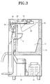
- FIG. 3 is a cross-sectional view showing an ice-making machine according to a preferred embodiment of the present invention,
- FIG. 4 is a cross-section view showing a part of the machine shown in FIG. 3; and
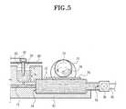
- FIG. 5 is a partial cross-sectional view illustrating the operation of the freezing unit of the ice-making machine shown in FIG. 3.
-
- Hereinbelow, an ice-making machine according to a preferred embodiment of the present invention is described with reference to the accompanying drawings. With respect to the elements identical to those shown in the prior art, like reference numerals will be assigned to indicate like elements.
- As shown in FIGS. 3 and 4, an ice-making machine according to the present invention includes a
housing 10, afreezing unit 60, and an air-removing means 70. - The
housing 10 has anice bin 11 for storing therein ice pieces formed in thefreezing unit 60. Under theice bin 11 are disposed acompressor 12 and acondenser 13 constituting a refrigeration or freezing system. At one side of theice bin 11 is provided a water collectingsection 15 for collecting unfrozen water. - The
freezing unit 60 includes abase frame 61, afreezing base plate 62, and anevaporator 50. Thebase frame 61 is pivotably disposed on thehousing 10 and has a plurality of freezingcells 63 for being filled with water to be frozen. When thebase frame 61 pivots on apivotal shaft 65 to a ) predetermined angle by a pivoting means 64, the unfrozen ice water in the freezingcells 63 is guided along thewater chute 66 and discharged out. The freezingcells 63 are formed having predetermined sizes, which take into consideration the sizes of the ice pieces and the water freezing speed, and the number of the freezing cells may range from 20 to 30, and preferably, number 27. - The
freezing base plate 62 is provided with theevaporator 50 disposed on the upper surface thereof and freezingfingers 67 formed on the lower surface thereof shaped and dimensioned to be dipped into the water supplied to each of thefreezing cells 63. Theevaporator 50 is connected to the freezing system so that refrigerant is allowed to flow inside theevaporator 50. The freezingfingers 67 are cooled at a temperature of 0° C or lower by heat exchange of the refrigerant flowing inside theevaporator 50 and thus the ice pieces are gradually frozen around the freezingfingers 67. - The air-
removing means 70 includes awater path 71 provided within thebase frame 61 to be connected to each of the freezingcells 63, awater pocket 72 in fluid communication with thewater path 71, and acam 73 for pressing thewater pocket 72 repeatedly. - The
water pocket 72 has anoutlet portion 74 in fluid communication with thewater path 71 and aninlet portion 75 at which avalve 76 is disposed. Thevalve 76 is used for regulating water supply from an external water supply throughpipe 16 to thewater pocket 72 by opening and closing theinlet portion 75. Thewater pocket 72 is made of soft material such as silicone and thus can be deformed by an external pressure. Accordingly, thewater pocket 72 shrinks under the external pressure of thecam 73 to thus inject a predetermined amount of the water to be frozen into thewater path 71 and increase the water level of the water in the freezingcells 63. When the external pressure is removed, thewater pocket 72 expands to its original shape so that the water is returned to thewater pocket 72. Accordingly, the water level decreases to the original level. - The
cam 73 for pressing thewater pocket 72 periodically is rotatably disposed at acam shaft 78 connected to acam motor 77. Between thecam 73 and thewater pocket 72 is disposed apressing plate 79. Thepressing plate 79 is for preventing damage that occurs due friction between thecam 73 and thewater pocket 72 and for increasing the area of thewater pocket 72 pressed by thecam 73. - Hereinbelow, the operation of the ice-making machine according to the present invention is described, referring to FIGS. 3, 4 and 5.
- When the
valve 76 disposed between thewater pocket 72 and thewater supply pipe 16 is opened, the water is forcedly injected into thewater pocket 72 by the water pressure in thepipe 16. The water of thewater pocket 72 flows into thewater path 71 via theoutlet portion 74 and then to thewater cells 63. When the water in the freezingcells 63 reaches a predetermined water level H1, thevalve 76 is closed to block further inflow of the water. At this time, thewater pocket 72 expands with the water filled therein. - After the water has been supplied and as the
cam motor 77 is activated, thecam 73 rotates in contact with thepressing plate 79 to press thewater pocket 72 periodically. Accordingly, thewater pocket 72 repeats shrinking and swelling to thus pump the water into the freezingcells 63, as shown by the dotted lines. Also, the water in the freezingcells 63 rocks upward and downward so that the water level goes up and down between the levels H1 and H2 with the repeated operation of thecam 73. - Due to the rocking movement of the water in the freezing
cells 63, air bubbles on the surfaces of the freezingfingers 67 float upwardly and out of the water. Accordingly, around the freezing fingers that are cooled at about -22°C, removal of the air bubbles from the water permits the water to be frozen to form clear ice pieces. - When the ice pieces are gradually formed around the freezing
fingers 67 to predetermined sizes, thecam 73 stops being rotated and thebase frame 61 pivots on thepivotal shaft 65 by action of the pivoting means 64. When thebase frame 61 is tilted toward a side, unfrozen water in the freezingcells 63 is guided along thewater chute 66 and discharged to thewater collecting section 15. Hot gas from thecompressor 12 is bypassed to theevaporator 50 without passing through thecondenser 13. Accordingly, as the freezingfingers 67 are heated to about 10° C, the ice pieces are separated from the freezingfingers 67 and are dropped into theice bin 11. - According to the present invention as described above, a predetermined amount of the water to be frozen is supplied to each of the plurality of freezing
cells 63 having a predetermined size. Accordingly, as the amount of the water to be supplied can be reduced, it provides an effect that waste of the water is prevented. - Moreover, according to the present invention, since the freezing
fingers 67 cooled to the temperature of 0° C or lower are dipped into the predetermined amount of the water supplied to the respective freezingcells 63, water freezing speed around the freezingfingers 67 is increased and thus the time required to form ice pieces is reduced. - The foregoing embodiment and advantages are merely exemplary and are not to be construed as limiting the present invention. The present teaching can be readily applied to other types of apparatus. The description of the present invention is intended to be illustrative, and not to limit the scope of the following claims. Many alternatives, modifications, and variations will be apparent to those skilled in the art. In the claims, means-plus-function clauses are intended to cover the structures described herein as performing the recited function and not only structural equivalents but also equivalent structures.
Claims (7)
- An ice making machine comprising:a housing;an evaporator connected to a freezing system;a base frame having a plurality of freezing cells for being filled with water to be frozen;a freezing base plate provided with the evaporator and freezing fingers formed on the lower surface of the freezing base plate to be dipped into the water supplied to the freezing cells; andan air removing means for pumping the water into the freezing cells to remove air bubbles inside the water, thereby forming clear ice pieces.
- The ice making machine of claim 1, wherein the air removing means comprises:a water path disposed in the base frame to be connected to the freezing cells;a water pocket connected to the water path and being replenished with the water from an external water supply; anda pressing means for repeatedly pressing the water pocket to thereby pump the water in the water pocket into each freezing cell.
- The ice making machine of claim 1, wherein the pressing means comprises:a cam disposed in contact with the water pocket; anda cam motor for rotating the cam.
- The ice making machine of claim 2 or 3, wherein at a side of the water pocket is disposed a valve in line with the water path for forcedly injecting the water into the freezing cells.
- The ice making machine of claim 2, 3, or 4, wherein the water pocket is made of a soft impermeable material.
- The ice making machine of claim 2, 3, 4 or 5 wherein the water pocket is made of silicone.
- The ice making machine of claim 3 or claims 4, 5 or 6, when appendant directly or indirectly to claim 3, wherein between the cam and the water pocket is interposed a pressing plate.
Applications Claiming Priority (2)
| Application Number | Priority Date | Filing Date | Title |
|---|---|---|---|
| KR1020020066736A KR20040039089A (en) | 2002-10-31 | 2002-10-31 | Ice making machine |
| KR2002066736 | 2002-10-31 |
Publications (1)
| Publication Number | Publication Date |
|---|---|
| EP1416237A2 true EP1416237A2 (en) | 2004-05-06 |
Family
ID=30768223
Family Applications (1)
| Application Number | Title | Priority Date | Filing Date |
|---|---|---|---|
| EP03252864A Withdrawn EP1416237A2 (en) | 2002-10-31 | 2003-05-07 | Ice making machine |
Country Status (6)
| Country | Link |
|---|---|
| US (1) | US6688130B1 (en) |
| EP (1) | EP1416237A2 (en) |
| JP (1) | JP2004150786A (en) |
| KR (1) | KR20040039089A (en) |
| CN (1) | CN1493832A (en) |
| RU (1) | RU2232360C1 (en) |
Cited By (1)
| Publication number | Priority date | Publication date | Assignee | Title |
|---|---|---|---|---|
| CN105157300A (en) * | 2015-10-14 | 2015-12-16 | 苏州路之遥科技股份有限公司 | Flexible membrane air pressure sensing infrared ice machine |
Families Citing this family (46)
| Publication number | Priority date | Publication date | Assignee | Title |
|---|---|---|---|---|
| CN100412474C (en) * | 2006-07-16 | 2008-08-20 | 戴进军 | Water stirring mechanism of ice machine |
| EP1918663B1 (en) * | 2006-10-31 | 2010-09-15 | Electrolux Home Products Corporation N.V. | Device and method for automatically producing clear ice, and refrigerator featuring such a device |
| KR20090019322A (en) * | 2007-08-20 | 2009-02-25 | 엘지전자 주식회사 | Ice maker and refrigerator using the same |
| US20090211266A1 (en) * | 2008-02-27 | 2009-08-27 | Young Jin Kim | Method of controlling ice making assembly for refrigerator |
| KR20090092384A (en) * | 2008-02-27 | 2009-09-01 | 엘지전자 주식회사 | Ice making assembly for a refrigerator and method for sensing a water level thereof |
| US8434321B2 (en) * | 2008-02-27 | 2013-05-07 | Lg Electronics Inc. | Ice making assembly for refrigerator and method for controlling the same |
| KR101480549B1 (en) * | 2008-02-28 | 2015-01-08 | 엘지전자 주식회사 | Deicing device of refrigerator and control method thereof |
| KR101457691B1 (en) * | 2008-03-10 | 2014-11-03 | 엘지전자 주식회사 | Controlling method of an ice making assembly for refrigerator |
| WO2010099454A2 (en) * | 2009-02-28 | 2010-09-02 | Electrolux Home Products, Inc. | Method and apparatus for making clear ice |
| JP2010223481A (en) * | 2009-03-23 | 2010-10-07 | Mitsubishi Electric Corp | Ice making equipment |
| CN102192625B (en) * | 2010-03-10 | 2014-05-07 | 株式会社东芝 | refrigerator |
| US9217596B2 (en) | 2010-04-28 | 2015-12-22 | Electrolux Home Products, Inc. | Mechanism for ice creation |
| CN101963420A (en) * | 2010-09-21 | 2011-02-02 | 杨红波 | Ice making system |
| US8756951B2 (en) | 2011-06-22 | 2014-06-24 | Whirlpool Corporation | Vertical ice maker producing clear ice pieces |
| US9127871B2 (en) | 2011-06-22 | 2015-09-08 | Whirlpool Corporation | Ice making, transferring, storing and dispensing system for a refrigerator |
| US8695359B2 (en) | 2011-06-22 | 2014-04-15 | Whirlpool Corporation | Water circulation and drainage system for an icemaker |
| US8844314B2 (en) * | 2011-06-22 | 2014-09-30 | Whirlpool Corporation | Clear ice making system and method |
| US8919145B2 (en) | 2011-06-22 | 2014-12-30 | Whirlpool Corporation | Vertical ice maker with microchannel evaporator |
| US8950197B2 (en) | 2011-06-22 | 2015-02-10 | Whirlpool Corporation | Icemaker with swing tray |
| US9513045B2 (en) | 2012-05-03 | 2016-12-06 | Whirlpool Corporation | Heater-less ice maker assembly with a twistable tray |
| US8925335B2 (en) | 2012-11-16 | 2015-01-06 | Whirlpool Corporation | Ice cube release and rapid freeze using fluid exchange apparatus and methods |
| US9500398B2 (en) | 2012-12-13 | 2016-11-22 | Whirlpool Corporation | Twist harvest ice geometry |
| US9599388B2 (en) | 2012-12-13 | 2017-03-21 | Whirlpool Corporation | Clear ice maker with varied thermal conductivity |
| US9470448B2 (en) | 2012-12-13 | 2016-10-18 | Whirlpool Corporation | Apparatus to warm plastic side of mold |
| US9557087B2 (en) | 2012-12-13 | 2017-01-31 | Whirlpool Corporation | Clear ice making apparatus having an oscillation frequency and angle |
| US9410723B2 (en) | 2012-12-13 | 2016-08-09 | Whirlpool Corporation | Ice maker with rocking cold plate |
| US9310115B2 (en) | 2012-12-13 | 2016-04-12 | Whirlpool Corporation | Layering of low thermal conductive material on metal tray |
| US9273891B2 (en) | 2012-12-13 | 2016-03-01 | Whirlpool Corporation | Rotational ice maker |
| US9599385B2 (en) | 2012-12-13 | 2017-03-21 | Whirlpool Corporation | Weirless ice tray |
| US9303903B2 (en) | 2012-12-13 | 2016-04-05 | Whirlpool Corporation | Cooling system for ice maker |
| US9476629B2 (en) | 2012-12-13 | 2016-10-25 | Whirlpool Corporation | Clear ice maker and method for forming clear ice |
| US9518770B2 (en) | 2012-12-13 | 2016-12-13 | Whirlpool Corporation | Multi-sheet spherical ice making |
| US9518773B2 (en) | 2012-12-13 | 2016-12-13 | Whirlpool Corporation | Clear ice maker |
| US9068961B2 (en) | 2013-02-15 | 2015-06-30 | Shale Testing Solutions, Llc | Method and apparatus for measuring the radioactive content of materials |
| KR101507036B1 (en) * | 2013-11-21 | 2015-04-06 | 주식회사 아이씨티나까조 | Ice Making Tray moving apparatus for use of Ice Maker |
| KR101507037B1 (en) * | 2013-11-21 | 2015-04-03 | 주식회사 아이씨티나까조 | Ice dispenser Housing for use of ice maker |
| WO2016065269A2 (en) | 2014-10-23 | 2016-04-28 | Whirlpool Corporation | Method and apparatus for increasing rate of ice production in an automatic ice maker |
| CN105222450A (en) * | 2015-10-14 | 2016-01-06 | 苏州路之遥科技股份有限公司 | The infrared ice machine of a kind of mantle air pressure warming |
| US10739053B2 (en) | 2017-11-13 | 2020-08-11 | Whirlpool Corporation | Ice-making appliance |
| CN107883627A (en) * | 2017-12-15 | 2018-04-06 | 江苏高菱蓄能科技有限公司 | One kind automation ice maker |
| US10823475B2 (en) * | 2018-09-19 | 2020-11-03 | Haier Us Appliance Solutions, Inc. | Clear barrel ice maker |
| US10907874B2 (en) | 2018-10-22 | 2021-02-02 | Whirlpool Corporation | Ice maker downspout |
| CN109737657B (en) * | 2019-01-09 | 2021-01-12 | 广州峻威换热科技有限公司 | Automatic directly freeze formula transparent ice cube ice machine |
| JP7458054B2 (en) * | 2019-12-09 | 2024-03-29 | アクア株式会社 | Ice maker and refrigerator with ice maker |
| US20210222933A1 (en) * | 2020-01-16 | 2021-07-22 | Haier Us Appliance Solutions, Inc. | Ice-making appliances and methods for dispensing ice above a sink |
| US11620624B2 (en) | 2020-02-05 | 2023-04-04 | Walmart Apollo, Llc | Energy-efficient systems and methods for producing and vending ice |
Citations (1)
| Publication number | Priority date | Publication date | Assignee | Title |
|---|---|---|---|---|
| US5425243A (en) | 1992-08-05 | 1995-06-20 | Hoshizaki Denki Kabushiki Kaisha | Mechanism for detecting completion of ice formation in ice making machine |
Family Cites Families (11)
| Publication number | Priority date | Publication date | Assignee | Title |
|---|---|---|---|---|
| US3791166A (en) * | 1972-06-26 | 1974-02-12 | L Maleck | Clear ice pellet maker |
| DE2647541C3 (en) * | 1976-10-21 | 1979-11-08 | Theo 6751 Mackenbach Wessa | Method and device for producing clear small ice cubes |
| US4572785A (en) * | 1984-03-29 | 1986-02-25 | Melvin Braaten | Water purifier unit |
| US4685304A (en) * | 1986-02-13 | 1987-08-11 | Essig Robert A | Method and apparatus for forming cube of frozen liquid |
| JPH0281371U (en) * | 1988-12-07 | 1990-06-22 | ||
| JPH0733943B2 (en) * | 1989-11-15 | 1995-04-12 | 株式会社東芝 | Automatic ice machine |
| DE4012249A1 (en) * | 1990-04-14 | 1991-10-17 | Gaggenau Werke | DEVICE FOR THE PRODUCTION OF CLEAR TISSUES AND CONTROL CIRCUIT TO THEREFORE |
| JPH05106952A (en) * | 1991-10-14 | 1993-04-27 | Sharp Corp | Automatic ice machine |
| US5187948A (en) * | 1991-12-31 | 1993-02-23 | Whirlpool Corporation | Clear cube ice maker |
| JPH09203573A (en) * | 1996-01-25 | 1997-08-05 | Furukawa Electric Co Ltd:The | Ice maker |
| JPH1047824A (en) * | 1996-08-05 | 1998-02-20 | Hoshizaki Electric Co Ltd | Ice making portion of ice machine |
-
2002
- 2002-10-31 KR KR1020020066736A patent/KR20040039089A/en not_active Ceased
-
2003
- 2003-02-07 JP JP2003031263A patent/JP2004150786A/en not_active Withdrawn
- 2003-04-22 US US10/420,479 patent/US6688130B1/en not_active Expired - Fee Related
- 2003-05-07 EP EP03252864A patent/EP1416237A2/en not_active Withdrawn
- 2003-05-20 RU RU2003114923/12A patent/RU2232360C1/en not_active IP Right Cessation
- 2003-05-21 CN CNA031378110A patent/CN1493832A/en active Pending
Patent Citations (1)
| Publication number | Priority date | Publication date | Assignee | Title |
|---|---|---|---|---|
| US5425243A (en) | 1992-08-05 | 1995-06-20 | Hoshizaki Denki Kabushiki Kaisha | Mechanism for detecting completion of ice formation in ice making machine |
Cited By (1)
| Publication number | Priority date | Publication date | Assignee | Title |
|---|---|---|---|---|
| CN105157300A (en) * | 2015-10-14 | 2015-12-16 | 苏州路之遥科技股份有限公司 | Flexible membrane air pressure sensing infrared ice machine |
Also Published As
| Publication number | Publication date |
|---|---|
| CN1493832A (en) | 2004-05-05 |
| KR20040039089A (en) | 2004-05-10 |
| US6688130B1 (en) | 2004-02-10 |
| RU2232360C1 (en) | 2004-07-10 |
| JP2004150786A (en) | 2004-05-27 |
Similar Documents
| Publication | Publication Date | Title |
|---|---|---|
| US6688130B1 (en) | Ice making machine | |
| US6647739B1 (en) | Ice making machine | |
| US6688131B1 (en) | Ice making machine | |
| US6742351B2 (en) | Ice making machine | |
| EP0326144B1 (en) | Automatic ice making machine | |
| CN100436976C (en) | Water purification system and equipment for simultaneously producing ice and cold water with one evaporator | |
| KR101452762B1 (en) | Refrigerator | |
| JP2004053036A (en) | Transparent ice making device and transparent ice making method | |
| KR101391832B1 (en) | Freezing Unit and Ice Making Method using The Same | |
| US4884413A (en) | Ice machine | |
| CN101995128A (en) | Refrigeration water, ice making device and method | |
| CN219995609U (en) | Transparent bullet head ice maker | |
| CN100412474C (en) | Water stirring mechanism of ice machine | |
| KR102468817B1 (en) | Ice making device | |
| CN214148503U (en) | Heat recovery system for refrigeration house | |
| KR102470382B1 (en) | Structure that combines the ice making water tank in the cleaning unit of the drum type the ice maker | |
| JPH11257809A (en) | Ice making structure of water-storage-type ice machine | |
| JPH083895Y2 (en) | Uniced water recovery structure of automatic ice maker | |
| JPS5840471A (en) | automatic ice maker | |
| KR200480759Y1 (en) | Snow ice maker | |
| JP2005077028A (en) | Ice making machine | |
| WO2022007849A1 (en) | Refrigeration appliance having ice-making assembly, and cleaning method | |
| CN121220936A (en) | Drinking water equipment | |
| JPH1194412A (en) | Cotton ice melting structure of ice machine | |
| JP2004036951A (en) | Ice maker |
Legal Events
| Date | Code | Title | Description |
|---|---|---|---|
| PUAI | Public reference made under article 153(3) epc to a published international application that has entered the european phase |
Free format text: ORIGINAL CODE: 0009012 |
|
| AK | Designated contracting states |
Kind code of ref document: A2 Designated state(s): AT BE BG CH CY CZ DE DK EE ES FI FR GB GR HU IE IT LI LU MC NL PT RO SE SI SK TR |
|
| AX | Request for extension of the european patent |
Extension state: AL LT LV MK |
|
| STAA | Information on the status of an ep patent application or granted ep patent |
Free format text: STATUS: THE APPLICATION IS DEEMED TO BE WITHDRAWN |
|
| 18D | Application deemed to be withdrawn |
Effective date: 20051201 |