EP1416199A2 - Engaging force control of lockup clutch - Google Patents
Engaging force control of lockup clutch Download PDFInfo
- Publication number
- EP1416199A2 EP1416199A2 EP03020288A EP03020288A EP1416199A2 EP 1416199 A2 EP1416199 A2 EP 1416199A2 EP 03020288 A EP03020288 A EP 03020288A EP 03020288 A EP03020288 A EP 03020288A EP 1416199 A2 EP1416199 A2 EP 1416199A2
- Authority
- EP
- European Patent Office
- Prior art keywords
- rotation speed
- relative rotation
- erev
- target
- engine rotation
- Prior art date
- Legal status (The legal status is an assumption and is not a legal conclusion. Google has not performed a legal analysis and makes no representation as to the accuracy of the status listed.)
- Granted
Links
Images


Classifications
-
- F—MECHANICAL ENGINEERING; LIGHTING; HEATING; WEAPONS; BLASTING
- F16—ENGINEERING ELEMENTS AND UNITS; GENERAL MEASURES FOR PRODUCING AND MAINTAINING EFFECTIVE FUNCTIONING OF MACHINES OR INSTALLATIONS; THERMAL INSULATION IN GENERAL
- F16H—GEARING
- F16H61/00—Control functions within control units of change-speed- or reversing-gearings for conveying rotary motion ; Control of exclusively fluid gearing, friction gearing, gearings with endless flexible members or other particular types of gearing
- F16H61/14—Control of torque converter lock-up clutches
- F16H61/143—Control of torque converter lock-up clutches using electric control means
-
- F—MECHANICAL ENGINEERING; LIGHTING; HEATING; WEAPONS; BLASTING
- F16—ENGINEERING ELEMENTS AND UNITS; GENERAL MEASURES FOR PRODUCING AND MAINTAINING EFFECTIVE FUNCTIONING OF MACHINES OR INSTALLATIONS; THERMAL INSULATION IN GENERAL
- F16H—GEARING
- F16H59/00—Control inputs to control units of change-speed-, or reversing-gearings for conveying rotary motion
- F16H59/36—Inputs being a function of speed
- F16H2059/366—Engine or motor speed
-
- F—MECHANICAL ENGINEERING; LIGHTING; HEATING; WEAPONS; BLASTING
- F16—ENGINEERING ELEMENTS AND UNITS; GENERAL MEASURES FOR PRODUCING AND MAINTAINING EFFECTIVE FUNCTIONING OF MACHINES OR INSTALLATIONS; THERMAL INSULATION IN GENERAL
- F16H—GEARING
- F16H61/00—Control functions within control units of change-speed- or reversing-gearings for conveying rotary motion ; Control of exclusively fluid gearing, friction gearing, gearings with endless flexible members or other particular types of gearing
- F16H61/14—Control of torque converter lock-up clutches
- F16H61/143—Control of torque converter lock-up clutches using electric control means
- F16H2061/145—Control of torque converter lock-up clutches using electric control means for controlling slip, e.g. approaching target slip value
Definitions
- This invention relates to control of a lockup clutch provided to a torque converter for a vehicle.
- a torque converter installed between an engine and an automatic transmission of a vehicle transmits torque between a pump impeller and a turbine runner via a fluid. Since the relative rotation between the pump impeller and the turbine runner increases fuel consumption of the engine, it is preferable to directly connect the pump impeller and the turbine runner soon after the vehicle is started up.
- a lockup clutch is provided to accomplish this purpose.
- a change-over between a converter mode where the torque is transmitted via a fluid and a lockup mode where the torque is transmitted via the lockup clutch is performed via a slip mode where a slip in the lockup clutch is allowed such that a part of the torque is transmitted via the fluid while the other part of the torque is transmitted via the lockup clutch.
- a hydraulic pressure supplied to the lockup clutch and the engine operation is controlled in order to cause the relative rotation speed of the pump impeller and the turbine runner to gradually become zero.
- United States Patent serial No. 6,066,072 discloses a feedback control device of the relative rotation speed between the pump impeller and the turbine runner in the slip mode.
- This device sets a target relative rotation speed in the slip mode, and controls the hydraulic pressure supplied to the lockup clutch and the engine operation such that the deviation of the real relative rotation speed from the target relative rotation speed decreases.
- the device is provided with a pre-processing compensation unit which apples a first order delay to the target relative rotation speed in order to enhance control response characteristics while maintaining an appropriate redundancy to absorb the effect of engine rotation speed variation.
- the device when the real variation of the relative rotation speed does not comply with a reference model applied to the pre-processing compensating unit, for example, when the engine rotation speed is low at the commencement of the slip mode, a target engine speed corresponding to the set target relative rotation speed will be much larger than the real engine rotation speed.
- the device then lowers the hydraulic pressure supplied to the lockup clutch in order to eliminate the deviation of the real engine rotation speed from the target engine rotation speed. If the hydraulic pressure supplied to the lockup clutch is lowered, however, a smooth engagement of the lockup clutch is not possible.
- this invention provides an engaging force control device of a lockup clutch for use with a torque converter for a vehicle.
- the lockup clutch engages a pump impeller connected to the engine with a turbine runner connected to an input shaft of an automatic transmission according to an engaging force.
- the engaging force control device comprises a sensor which detects an engine rotation speed ( EngREV ), a sensor which detects an input rotation speed ( PriREV ) of the automatic transmission, an engaging force regulating mechanism which regulates the engaging force of the lockup clutch; and a programmable controller.
- the programmable controller is programmed to calculate a relative rotation speed ( ⁇ SLPR ) of the pump impeller and the turbine runner from the engine rotation speed ( EngREV ) and the input rotation speed ( PriREV ) of the automatic transmission, compare an initial engine rotation speed ( ST _ EREV ) which corresponds to an engine rotation speed when control of the engaging force is started, with a predetermined target engine rotation speed ( TGT_EREV ), set a target relative rotation speed ( ⁇ SLPT ), when the initial engine rotation speed ( ST_EREV ) is equal to or greater than the predetermined target engine rotation speed ( TGT_EREV ), according to a difference between the target engine rotation speed ( TGT_EREV ) and the input rotation speed ( PriREV ) of the automatic transmission, set the target relative rotation speed ( ⁇ SLPT ), when the initial engine rotation speed ( ST_EREV ) is smaller than the predetermined target engine rotation speed ( TGT_EREV ), to gradually vary from an initial relative rotation speed ( ST_EREV
- This invention also provides an engaging force control method of a lockup clutch for use with a torque converter for a vehicle.
- the lockup clutch engages a pump impeller connected to the engine with a turbine runner connected to an input shaft of an automatic transmission according to an engaging force regulated by an engaging force regulating mechanism.
- the method comprises determining an engine rotation speed ( EngREV ), determining an input rotation speed ( PriREV ) of the automatic transmission, calculating a relative rotation speed ( ⁇ SLPR ) of the pump impeller and the turbine runner from the engine rotation speed ( EngREV ) and the input rotation speed ( PriREV ) of the automatic transmission, comparing an initial engine rotation speed ( ST_EREV ) which corresponds to an engine rotation speed when control of the engaging force is started, with a predetermined target engine rotation speed ( TGT_EREV ), setting a target relative rotation speed ( ⁇ SLPT ), when the initial engine rotation speed ( ST_EREV ) is equal to or greater than the predetermined target engine rotation speed ( TGT_EREV ), according to a difference between the target engine rotation speed ( TGT_EREV ) and the input rotation speed ( PriREV ) of the automatic transmission, setting the target relative rotation speed ( ⁇ SLPT ), when the initial engine rotation speed ( ST_EREV ) is smaller than the predetermined target engine rotation speed (
- FIG. 1 is a schematic diagram of a vehicle power train provided with a lockup clutch to which this invention is applied.
- FIG. 2 is a schematic diagram of an engaging force control device according to this invention.
- FIG. 3 is a block diagram describing the functions of a controller according to this invention.
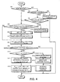
- FIG. 4 is a flowchart describing an engaging force control routine executed by the controller.
- FIG. 5 is a flowchart describing a differential pressure setting subroutine executed by the controller.
- FIG. 6 is a flowchart describing a subroutine for setting a target relative rotation speed ⁇ SLPT and a time constant Tc executed by the controller.
- FIG. 7 is a flowchart describing a subroutine for setting an initial value ST _ TC of the time constant Tc executed by the controller.
- FIG. 8 is a diagram describing the characteristics of a map of a relative rotation gain g SLPC stored by the controller.
- FIG. 9 is a diagram describing the characteristics of an engine performance map stored by the controller.
- FIG. 10 is a diagram describing the characteristics of a map of a tightening capacity t LUC of the lockup clutch stored by the controller.
- FIG. 11 is a diagram describing the characteristics of a map of an initial differential pressure stored by the controller.
- FIG. 12 is a diagram describing the characteristics of a map of an open-loop control cessation determination speed ⁇ SLPMAP stored by the controller.
- FIG. 13 is a diagram describing the characteristics of a map of a target increase rate t ⁇ P stored by the controller.
- FIG. 14 is a diagram describing the characteristics of a map of a target engine rotation speed TGT_EREV stored by the controller.
- FIG. 15 is a diagram describing the characteristics of a map of the time constant Tc stored by the controller.
- FIGs. 16A-16E are timing charts describing a result of the engaging force control performed by the controller when an initial engine rotation speed ST_EREV is larger than the target engine rotation speed TGT_EREV .
- FIGs. 17A-17E are similar to FIGs. 16A-16E, but showing a case where the initial engine rotation speed ST_EREV is not larger than the target engine rotation speed TGT_EREV
- FIGs. 18A-18E are similar to FIGs. 17A-17E, but showing a case where a target change-over relative rotation speed CHG_SREV is limited by the initial relative rotation speed ST_SREV .
- FIGs. 19A-19F are timing charts describing a result of the engaging force control performed by the controller in a case where the time constant Tc is set to have a large value.
- FIGs. 20A-20F are similar to FIGs. 19A-19F, but showing a case where the time constant Tc is set to have a small value.
- FIGs. 21A-21F are similar to FIGs. 19A-19F, but showing a case where the time constant Tc is set to vary.
- FIG. 22 is a flowchart describing a subroutine for changing over a target relative rotation speed ⁇ SLTP and the time constant Tc executed by a controller according to a second embodiment of this invention.
- FIGs. 23A-23F are timing charts describing a result of the engaging force control performed by the controller according to the second embodiment of this invention.
- FIGs. 24A-24E are timing charts describing a result of the engaging force control according to a prior art engaging force control device.
- a multi-cylinder engine 1 for a vehicle is connected to an automatic transmission 3 via a torque converter 2, and the output of the automatic transmission 3 is transmitted to drive wheels 5 via a differential 4.
- the automatic transmission 3 is constituted by a continuously variable transmission.
- the torque converter 2 comprises a pump impeller 2a driven by the engine 1, a turbine runner 2b connected to the input shaft of the automatic transmission 3, and a lockup clutch 2c which directly connects the turbine runner 2b with the pump impeller 2a.
- the tightening force of the lockup clutch 2c is determined by the pressure difference between an application pressure PA and release pressure PR . These pressures are provided in the form of pressurized oil from a control valve 11.
- the lockup clutch 2c is in a released state, and the pump impeller 2a and turbine runner 2b rotate due to the torque transmission function of the fluid interposed therebetween.
- the torque converter 2 Before a lockup state and while relative rotation is still possible, the torque converter 2 transmits torque in two ways, i.e. via the fluid and via mechanical transmission by the lockup clutch 2c.
- the engine output torque is equal to the sum of these torques.
- the transmission torque of the lockup clutch 2c is expressed as a tightening capacity of the lockup clutch 2c.
- the control valve 11 supplies the application pressure PA and release pressure PR to the lockup clutch 2c according to a signal pressure Ps input from a solenoid valve 13.
- the pressure difference between the application pressure PA and release pressure PR i.e., the tightening pressure of the lockup clutch 2c, varies according to the signal pressure Ps .
- the control valve 11 comprises a spool.
- the application pressure PA and a resilient force of a spring 11a are exerted on one end of the spool and the release pressure PR and the signal pressure Ps are exerted on the other side of the spool.
- the spool displaces according to the balance of these pressures and forces so as to generate the pressure difference PA - PR corresponding to the signal pressure Ps .
- the solenoid valve 13 is duty controlled according to a duty signal D from a controller 12, and the corresponding signal pressure Ps is generated from a predetermined pilot pressure Pp as shown in FIG. 2. That is, the signal pressure Ps is increased as the duty ratio of the duty signal D increases.
- signals are input to the controller 12 from a throttle opening sensor 21 which detects a throttle opening TVO of the engine 1, an impeller rotation sensor 22 which detects a rotation speed ⁇ IR of the pump impeller 2a, a turbine rotation sensor 23 which detects a rotation speed ⁇ TR of the turbine runner 2b, an oil temperature sensor 24 which detects an oil temperature T ATF in the automatic transmission 3, a vehicle speed sensor 25 which detects a vehicle speed VSP , a gear ratio calculating unit 26, and a voltage sensor 28 which detects a voltage of a power source which supplies electric power to the solenoid valve 13.
- the rotation speed ⁇ IR of the pump impeller 2a is also used as an engine rotation speed EngREV.
- the rotation speed ⁇ TR of the turbine runner 2b is also used as an input rotation speed RriREV of the automatic transmission 3.
- the gear ratio calculating unit 26 calculates a real gear ratio ip of the automatic transmission 3 from the rotation speed ⁇ TR of the turbine runner and the vehicle speed VSP , and inputs it to the controller 12.
- the controller 12 comprises a microcomputer provided with a central processing unit (CPU), read-only memory ROM), random-access memory (RAM), and an input/output interface.
- the gear ratio calculating unit 26 also comprises a similar microcomputer.
- the controller 12 may comprise plural microcomputers.
- the controller 12 and the gear ratio calculating unit 26 may also be realized by one microcomputer.
- the controller 12 generates the duty signal D on the basis of the above signals by performing an engaging force control routine shown in FIG. 4.
- This routine is executed at intervals of twenty milliseconds when the engine 1 is operating.
- the controller 12 determines whether or not the running condition of the vehicle corresponds to the slip region of the torque converter 2.
- the slip region corresponds to a region where the vehicle speed VSP is within a predetermined range while the throttle opening TVO is not larger than a predetermined opening TVO1 .
- the controller 12 When, in the step S2, the vehicle operating condition corresponds to the slip region, the controller 12 performs the processing of a step S5. When the vehicle operating condition does not correspond to the slip region, the controller 12 determines in a step S3 whether the vehicle operating condition corresponds to the lockup region. When the vehicle operating condition does not correspond to the slip region, it must correspond to the lockup region or converter region. In the step S3, when the vehicle speed VSP is less than a predetermined vehicle speed, it is determined that the operating condition corresponds to the converter region, and if the vehicle speed is not less than the predetermined vehicle speed, it is determined that the operating condition corresponds to the lockup region.
- the predetermined vehicle speed is herein set to five kilometers per hour (5km/hr).
- the differential pressure ( PA-PR ) is controlled so that the application pressure PA is lower than the release pressure PR .
- PA-PR the differential pressure
- the output rotation of the engine 1 is exclusively transmitted to the automatic transmission 3 via the fluid in the torque converter 2.
- the controller 12 determines whether or not the lockup operation of the lockup clutch 2c has been completed. In other words, it determines if the differential pressure ( PA-PR ) of the lockup clutch 2c has reached a predetermined lockup differential pressure. As the differential pressure ( PA-PR ) is produced as a result of the duty signal D which the controller 12 outputs to the solenoid valve 13, the differential pressure ( PA-PR ) is a value known by the controller 12.
- the controller 12 performs the processing of the step S5 as in the case where the operating condition corresponds to the slip region.
- the controller 12 determines whether the processing of the converter region, i.e., the release processing of the lockup clutch 2c of the step S17, was performed on the immediately preceding occasion the routine was executed. In other words, it is determined whether or not the step S5 is performed for the first time since the vehicle speed VSP exceeded 5km/hour in the step S2.
- step S6 the controller 12 sets the current differential pressure ( PA-PR ) using a subroutine shown in FIG. 5.
- the controller 12 calculates an initial differential pressure of the lockup clutch 2c from the throttle opening TVO detected by the throttle opening sensor 21 by looking up a map having the characteristics shown in FIG. 11. This map is prestored in the memory (ROM) of the controller 12.
- the controller 12 determines whether or not the initial differential pressure is larger than the current differential pressure command value.
- the current differential pressure command value is the differential pressure corresponding to the newest duty signal D currently outputted to the solenoid valve 13 from the controller 12.
- a step S62 the controller 12 sets the current differential pressure ( PA-PR ) to equal the initial differential pressure.
- the controller 12 sets the current differential pressure ( PA-PR ) to equal the current differential pressure command value in a step S63. After the processing of the step S62 or the step S63, the controller 12 terminates the subroutine.
- the controller 12 sets an open-loop control flag to unity.
- the open-loop control flag is a flag which shows that open loop control of the differential pressure of the lockup clutch 2c is performed, and its initial value is zero.
- the controller 12 After the processing of the step S7, the controller 12 performs the processing of a step S8.
- the controller 12 skips the steps S6 and S7, and performs the processing of the step S8.
- the controller 12 calculates an open-loop control cessation determination speed ⁇ SLPMAP from the throttle opening TVO by looking up a map having the characteristics shown in FIG. 12. This map is prestored in the memory (ROM) of the controller 12.
- the open-loop control cessation determination speed ⁇ SLPMAP is the relative rotation speed of the pump impeller 2a and turbine runner 2b which is used to determine whether or not to terminate open loop control of the differential pressure ( PA-PR ) or, in other words, the engaging force of the lockup clutch 2.
- the open-loop control cessation determination speed ⁇ SLPMAP increases as the throttle opening TVO becomes larger, as shown in the figure.
- the controller 12 determines whether or not the open loop flag has a value of unity.
- the open loop flag does not have a value of unity, it shows that the lockup clutch 2c is in the slip region, and open loop control is not performed.
- the controller 12 open loop control is performed in the first half of the slip region, and feedback control is performed in the second half.
- the controller 12 performs feedback control of the differential pressure ( PA-PR ) in a step S15. This feedback control is described later.
- the controller 12 compares the open-loop control cessation determination speed ⁇ SLPMAP with the current real relative rotation speed ⁇ SLPR in a step S10.
- the real relative rotation speed ⁇ SLPR is the difference of the rotation speed ⁇ IR of the pump impeller 2a, and the rotation speed ⁇ TR of the turbine runner 2b.
- the controller 12 in a step S11, calculates a target increase rate t ⁇ P of the differential pressure ( PA-PR ) in open loop control.
- This calculation is performed by looking up a map having the characteristics shown in FIG. 13 using the throttle opening TVO .
- This map is prestored in the memory (ROM) of the controller 12.
- the target increase rate t ⁇ P increases as the throttle opening TVO increases.
- the increase rate t ⁇ P is set equal to 0.0012 megapascals (MPa) per twenty milliseconds when the throttle opening TVO is 0/8 and to 0.0035 megapascals (MPa) per twenty milliseconds when the throttle opening TVO is 8/8. Twenty milliseconds corresponds to the execution interval of the routine.
- step S12 the controller 12 sets a value obtained by adding the target increase rate t ⁇ P to the current differential pressure ( PA-PR ) as a target differential pressure P LUC , and outputs a duty signal D corresponding to the target differential pressure P LUC to the solenoid valve 13. After the processing of the step S12, the controller 12 terminates the routine.
- the controller 12 in a step S13, initializes the feedback control system. This is a measure for shifting to feedback control from open loop control of the differential pressure ( PA-PR ).
- step S14 the controller 12 resets the open-loop control flag to zero.
- step S15 the controller 12 performs feedback control of the differential pressure ( PA-PR ). After the processing of the step S15, the controller 12 terminates the routine.
- the processing of the steps S10-S12 corresponds to the open loop control of the differential pressure ( PA-PR ).
- the processing of the steps S13 and S14 corresponds to the change-over from open loop control to feedback control of the differential pressure ( PA-PR ).
- the processing of the step S15 corresponds to feedback control of the differential pressure ( PA-PR ).
- controller 12 for this purpose may be expressed by the blocks shown in FIG. 3. All the blocks shown in the figure are virtual units for the purpose of describing the function of the controller 12, and do not exist as physical entities.
- a target relative rotation speed calculating unit 100 determines a target relative rotation speed ⁇ SLPT of the pump impeller 2a and turbine runner 2b based on the vehicle speed VSP , throttle opening TVO , gear ratio ip and oil temperature T ATF .
- the target relative rotation speed ⁇ SLPT is the relative rotation speed which obtains a minimum fluctuation in the engine output torque due to scatter in the combustion of the engine 1 and a minimum pulsation noise emitted by the drive system. The determination of the target relative rotation speed ⁇ SLPT will be described later in detail.
- a real relative rotation computing unit 103 computes the real relative rotation speed ⁇ SLPR of the torque converter 2 by subtracting the rotation speed ⁇ TR of the turbine runner 2b from the rotation speed ⁇ IR of the pump impeller 2a.
- the rotation speed of the pump impeller 2a is equivalent to the rotation speed of the engine 1 and the rotation speed of the turbine runner 2b is equivalent to the input rotation speed of the automatic transmission 3.
- a pre-processing compensating unit 101 calculates a target relative rotation speed correction value ⁇ SLPTC by processing the target relative rotation speed ⁇ SLPT with a compensation filter so that the target relative rotation speed displays the intended response.
- the pre-processing compensating unit 101 comprises a first unit 101A and a second unit 101B.
- the first unit 101A calculates a first target relative rotation speed correction value ⁇ SLPTC1 from Equation (1) below.
- ⁇ SLPTC1 G R ( s ) ⁇ ⁇ SLPT ( t )
- G R ( s ) 1 1 + TC ⁇ s ,
- Equation (1) corresponds to a first order delay processing.
- the determination of the time constant Tc will be described below.
- the second unit 101B calculates a second target relative rotation speed correction value ⁇ SLPTC2 from Equation (2) below.
- ⁇ SLPTC2 G M ( s ) ⁇ ⁇ SLPT ( t )
- a feedback compensating unit 104 calculates the first relative rotation speed command value ⁇ SLPC1 on the basis of this deviation ⁇ SLPER using Equation (4) below which represents proportional/integral feedback control.
- ⁇ SLPC1 K P ⁇ ⁇ SLPER + K 1 s ⁇ ⁇ SLPER
- the feedback compensating unit 104 calculates a target relative rotation speed command value ⁇ SLPC by adding the second target relative rotation speed correction value ⁇ SLPTC2 to the first relative rotation speed command value ⁇ SLPC1 in Equation (5) below.
- ⁇ SLPC ⁇ SLPC1 + ⁇ SLPTC2
- a relative rotation gain computing unit 106 uses the rotation speed ⁇ TR of the turbine runner 2b to calculate the relative rotation gain g SLPC by referring to a map having the characteristics shown in FIG. 8.
- a target fluid transmission torque computing unit 105 calculates a target converter transmission torque t CNVC corresponding to the target relative rotation speed command value ⁇ SLPC using the relative rotation gain g SLPC using Equation (6) below.
- t CNVC ⁇ SLPC g SLPC
- a engine output torque estimating unit 108 looks up an engine output torque t ES of the engine 1 by referring to a map having the characteristics shown in FIG. 9 based on the engine rotation speed EngREV and throttle opening TVO .
- Equation (7) This value is filter processed by Equation (7) below using a time constant T ED taking account of a first order delay of the engine dynamics to obtain an engine torque estimated value t EH .
- t EH 1 1 + T ED ⁇ s ⁇ t ES
- a lockup clutch tightening pressure command value computing unit 109 calculates a lockup clutch tightening pressure command value P LUC required to achieve the target lockup clutch tightening capacity t LUC by referring to a map having the characteristics shown in FIG. 10.
- a solenoid drive signal computing unit 110 calculates a lockup duty S DUTY based on the lockup clutch tightening pressure command value P LUC , and outputs a corresponding duty signal D to the solenoid valve 13.
- This subroutine corresponds to the function of the target relative rotation speed calculating unit 100 and is performed by the controller 12 as a part of the step S15 of FIG. 4.
- the controller 12 sets a target engine rotation speed TGT_EREV from the throttle opening TVO by looking up a map having the characteristics shown in FIG. 14. This map is set such that the engine rotation speed undergoes continuous variation when the lockup clutch 2c engages from a slipping state, and is prestored in the memory (ROM) of the controller 12.
- the controller 12 sets a target relative rotation speed lower limit LMT_SREV according to the throttle opening TVO .
- LMT_SREV is set equal to 40 revolutions per minute (rpm) when the throttle opening TVO is 1/8
- LMT_SREV is set equal to 120 revolutions per minute (rpm) when the throttle opening TVO is 8/8.
- a next step S23 the controller 12 determines whether or not the current occasion is the first occasion the subroutine is executed. When the current occasion is the first occasion the subroutine is executed, the controller 12 executes the processing of a step S24. When the present occasion is not the first occasion the subroutine is executed, the controller 12 executes the processing of a step S26.
- the controller 12 stores the engine rotation speed EngREV as an initial engine rotation speed ST_EREV , the input rotation speed PriREV of the automatic transmission 3 as an initial input rotation speed ST_PREV of the automatic transmission 3, and the real relative rotation speed ⁇ SLPR as an initial relative rotation speed ST_SREV .
- These initial values are respectively stored in the memory (RAM). These initial values are referred to when the target relative rotation speed ⁇ SLPT and the time constant Tc are determined later.
- the controller 12 sets an initial value ST _TC of the time constant Tc .
- the setting is performed according to the initial engine rotation speed ST_EREV and the target engine rotation speed TGT_EREV by executing a subroutine of FIG. 7.
- the controller 12 in a first step S40 determines if the initial engine rotation speed ST_EREV is equal to or larger than the sum of the target engine rotation speed TGT_EREV and a maximum deviation EngERR which is a predetermined constant.
- step S40 When the determination result of the step S40 is affirmative, the controller 12 executes the processing of a step S41. When the determination result of the step S40 is negative, the controller 12 executes the processing of a step S42.
- the controller 12 sets the initial value ST_TC of the time constant Tc to equal a maximum value ST _TC_MAX .
- the controller 12 determines if the initial engine rotation speed ST_EREV is equal to or larger than the target engine rotation speed TGT_EREV .
- the controller 12 sets the initial value ST_TC of the time constant Tc to equal a minimum value ST _ TC_MIN in a step S44.
- the controller 12 sets the initial value ST_TC of the time constant Tc in a step S43 to a value between the maximum value ST_TC_MAX and the minimum value ST_TC_MIN using Equation (9) below.
- ST_TC ST_TC_MIN + ( ST_TC_MAX - ST_TC_MIM ) ⁇ ST_EREV ⁇ TGT_EREV EngERR
- the time constant Tc is set to a large value.
- the time constant Tc is set to a small value.
- the controller After setting the initial value ST_TC of the time constant Tc in the step S41, S43 or S44, the controller terminates the subroutine.
- the controller 12 executes the processing of the step S26.
- the controller 12 compares the initial engine rotation speed ST_EREV with the target engine rotation speed TGT_EREV .
- the controller 12 executes the processing of a step S27.
- the controller 12 executes the processing of a step S29 and subsequent steps.
- the controller 12 calculates the target relative rotation speed ⁇ SLPT using Equation (10) below.
- ⁇ SLPT TGT_EREV - PriREV
- Equation (10) is limited by the target relative rotation speed lower limit LMT_SREV calculated in the step S22.
- the controller executes the processing of a step S28.
- the controller determines if the initial relative rotation speed ST_SREV is larger than or equal to a predetermined target change-over relative rotation speed set value CHG_SREV_SET .
- the predetermined target change-over relative rotation speed set value CHG_SREV_SET is herein set to 40 revolutions per minute (rpm) when the throttle opening TVO is 1/8, and to 120 revolutions per minute (rpm) when the throttle opening TVO is 8/8.
- the controller executes the processing of a step S30, and when the determination result is negative, the controller 12 executes the processing of a step S31.
- the controller 12 sets a target change-over relative rotation speed CHG_SREV to equal the predetermined target change-over relative rotation speed set value CHG_SREV_SET .
- the target change-over relative rotation speed CHG_SREV is a value used for calculating a target change -over input rotation speed CHG_PREV of the automatic transmission 3 at which the calculation method of the target relative rotation speed ⁇ SLPT is changed over.
- the controller 12 sets the target change-over relative rotation speed CHG_SREV to equal the initial relative rotation speed ST_SREV .
- the target relative rotation speed ⁇ SLPT is prevented from increasing beyond the initial relative rotation speed ST_SREV as the lockup operation of the lockup clutch 2c progresses.
- the target relative rotation speed ⁇ SLPT takes a constant value. Therefore, the variation in the output of the feedforward compensator is suppressed, and deterioration in the control characteristics of the lockup clutch 2c due to unexpected decreases in the output of the feedforward compensator in the low relative rotation region can be prevented.
- the controller 12 calculates the target change-over input rotation speed CHG_PREV of the automatic transmission 3 using Equation (11) below in a step S32.
- CHG_PREV TGT_EREV - CHG_SREV
- a next step S33 the controller 12 determines if the input rotation speed PriREV of the automatic transmission 3 is larger than or equal to the target change-over input rotation speed CHG_PREV .
- the controller 12 calculates the target relative rotation speed ⁇ SLPT in the step S27 as described above.
- ⁇ SLPT CHG_SREV + ( ST_SREV - CHG_SREV ) ⁇ CHG_PREV - PriREV CHG_PREV - ST_PREV
- CHG_PREV is target change-over input rotation speed of the automatic transmission 3 calculated in the step S32
- ST_PREV is the initial input rotation speed of the automatic transmission 3 stored in the memory in the step S24
- PriREV is the current input rotation speed of the of the automatic transmission 3.
- step S28 by referring to a map having the characteristics shown in FIG. 15, the controller determines the time constant Tc .
- the time constant Tc decreases from the initial value ST _ TC which was determined in the step S25 according to the relation between the engine rotation speed EngREV and the target, engine rotation speed TGT_EREV , towards a constant value ED_TC .
- the characteristics of the time constant Tc to decrease is defined by a first order delay with a predetermined time constant CHG_TC .
- FIGs. 16A-16E show an example of the control results according to the above control by the controller 12 in a case where the engine rotation speed EngREV is larger than the target engine rotation speed TGT_EREV at the timing when the feedback control of the differential pressure ( PA-PR ) starts.
- the engine rotation speed EngREV and the input rotation speed PriREV of the automatic transmission 3 both increase, and the vehicle speed VSP also increases.
- the vehicle speed VSP exceeds 5km/hr at a time t1 , then the determination in the step S2 in FIG. 4 becomes affirmative and the controller 12 starts to perform an open loop control of the differential pressure.
- the difference between the target engine rotation speed TGT_EREV and the input rotation speed PriREV of the automatic transmission 3 in other words, the real relative rotation speed ⁇ SLPR ' equals the open-loop control cessation determination speed ⁇ SLPMAP .
- the controller 12 sets the target relative rotation speed ⁇ SLPT to equal the difference between the target engine rotation speed TGT_EREV and the input rotation speed PriREV of the automatic transmission 3 in the step S27 of FIG. 6. Afterwards, the controller 12 feedback controls the differential pressure ( PA-PR ) on the basis of the difference between the real relative rotation speed ⁇ SLPR and the target relative rotation speed ⁇ SLPT . According to this control, the relative rotation speed ⁇ SLPR smoothly decreases and reaches a value of zero at a time t4 as shown in FIG. 16A
- FIGs. 17A-17E and FIGs. 18A-18E show examples of the control results according to the above control by the controller 12 in a situation where the engine rotation speed EngREV at the time t2 when the feedback control of the differential pressure ( PA - PR ) is started is smaller than the target engine rotation speed TGT_EREV .
- FIGs. 24A-24E show the control results in a similar situation according to the prior art device.
- the engine rotation speed EngREV is smaller than the target engine rotation speed TGT_EREV as shown in FIG. 24A when the feedback control of the differential pressure ( PA-PR ) starts, and does not increase as expected due to an upward gradient, for example, the reference model output for the target relative rotation speed may increase immediately after the start of control as shown in FIG. 24B.
- the target engine rotation speed TGT_REV undergoes a conspicuous increase as shown by the dotted line in FIG. 24A.
- the differential pressure applied to the lockup clutch 2c is lowered as shown in FIG. 25E and smooth engagement of the lockup clutch is not possible.
- the controller 12 compares the engine rotation speed EngREV with the target engine rotation speed TGT_EREV in the step S26. If the engine rotation speed EngREV is smaller than the target engine rotation speed TGT_EREV , the controller 12 does not use the target engine rotation speed TGT_EREV for setting the target relative rotation speed ⁇ SLPT , but uses the target change-over relative rotation speed CHG_SREV which is the smaller of the predetermined target change-over relative rotation speed set value CHG_SREV_SET and the initial relative rotation speed ST_SREV . The controller 12 sets the target relative rotation speed ⁇ SLPT in the step S34 using the target change-over relative rotation speed CHG_SREV . This operation is continued, until the input rotation speed PriREV of the automatic transmission 3 becomes larger than the target change-over input rotation speed CHG_PREV .
- the target relative rotation speed ⁇ SLPT does not increase as in the prior art device even when the engine rotation speed EngREV is smaller than the target engine rotation speed TGT_EREV . Consequently, smooth engagement of the lockup clutch 2c is ensured.
- the controller 12 sets the target change-over relative rotation speed CHG_SREV to equal the predetermined target change-over relative rotation speed set value CHG_SREV_SET in the step S30.
- the input rotation speed PriREV of the automatic transmission 3 is smaller than the target change-over relative rotation speed CHG_SREV , so the target relative rotation speed ⁇ SLPT is set in the step S34 such that it converges to the target change-over relative rotation speed CHG_SREV from the initial relative rotation speed ST_SREV .
- the input rotation speed PriREV of the automatic transmission 3 reaches the target change-over input rotation speed CHG_PREV , and thereafter the target relative rotation speed ⁇ SLPT is set equal to the difference between the target engine rotation speed TGT_EREV and the input rotation speed PriREV of the automatic transmission 3 in the step S27 similar to the case of the FIGs. 16A-16E.
- the controller 12 sets the target change-over relative rotation speed CHG_SREV to equal the initial relative rotation speed ST_SREV .
- the target relative rotation speed ⁇ SLPT set in the step S34 takes a constant value as shown in FIG. 18B.
- the differential pressure ( PA-PR ) does not increase until the engine rotation speed EngREV becomes large enough to fully engage the lockup clutch 2c.
- the same processing as in the case of FIGs. 16A-16E or FIGs. 17A-17E is applied until the time t4 when the lockup clutch 2c completes lockup operation.
- FIGs. 19A-19E also shows an example of control resulting in the engine rotation speed EngREV being larger than the target engine rotation speed TGT_EREV at the commencement of feedback control on the differential pressure ( PA-PR ).
- the initial value of the first target relative rotation speed ⁇ SLPTC1 at the time t2 is set to equal the difference between the engine rotation speed EngREV and the input rotation speed PriREV as shown in FIGs 19A and 19C. Since the initial value of the first target relative rotation speed ⁇ SLPTC1 is set to equal the real relative rotation speed ⁇ SLPR , there is a large deviation ⁇ SLPER between the first target relative rotation speed ⁇ SLPTC1 and the target relative rotation speed ⁇ SLPT at the time t2 as shown in FIG. 19C.
- the initial value ST _ TC of the time constant Tc is set to equal the maximum value ST_TC_MAX in the step S41 when the engine rotation speed EngREV is larger than the sum of the target engine rotation speed TGT_EREV and a maximum deviation EngERR.
- the time constant Tc continue to take large values such as the maximum value ST _ TC_MAX until the end of the feedback control of the differential pressure ( PA-PR )
- PA-PR differential pressure
- the initial value ST_TC of the time constant Tc is set to equal the minimum value ST_TC_MIN in the step S44 of FIG. 7.
- the time constant Tc is fixed to the minimum value ST_TC_MIN throughout the feedback control period, there is no problem with respect to the control response of the differential pressure ( PA-PR ), because the first target relative rotation speed ⁇ SLPTC1 is quite close to the target relative rotation speed ⁇ SLPT at the time t2 .
- the time constant Tc is set to decrease from the initial value ST_Tc as time elapses in the step S28.
- FIGs. 21A-21F show the control results with the time constant Tc set in this way.
- the response in the feedback control of the differential pressure ( PA-PR ) can be improved due to the fact that the first target relative rotation speed ⁇ SLPTC1 smoothly approaches the real relative rotation speed ⁇ SLPR .
- the target relative rotation speed ⁇ SLTP and the time constant Tc were determined by the subroutine of FIG. 6. According to this embodiment, they are determined differently according to the vehicle speed VSP by executing a subroutine of FIG. 22 in the step S15 of FIG. 4.
- a first step S50 the controller 12 determines if the vehicle speed VSP is equal to or less than a predetermined first speed VSP1 .
- the controller 12 determines the target relative rotation speed ⁇ SLTP and the time constant Tc by executing the subroutine of FIG. 6 as the first embodiment.
- the controller 12 determines if the vehicle speed VSP is equal to or less than a predetermined second speed VSP2 .
- the controller 12 sets the target relative rotation speed ⁇ SLTP and the time constant Tc in a step S53.
- the target relative rotation speed ⁇ SLTP is set according to the throttle opening TVO .
- the controller 12 sets the target relative rotation speed ⁇ SLTP to zero revolutions per minute and sets an appropriate time constant Tc according to vehicle running conditions.
- the predetermined first speed VSP1 corresponds to a vehicle speed immediately previous to the up-shift operation of the automatic transmission 3.
- the predetermined second speed VSP2 corresponds to a vehicle speed at a timing when the input rotation speed of the automatic transmission 3 has become stable after up-shifting.
- the predetermined second speed VSP2 is naturally larger than the predetermined first speed VSP1 .
- the values for the predetermined first and second vehicle speeds VSP1 and VSP2 are determined on the basis of the speed change schedule applied to the automatic transmission 3. By determining the values of VSP1 and VSP2 in this way, the change-over of the setting methods of the target relative rotation speed ⁇ SLTP and the time constant Tc is well adapted to the upshift of the automatic transmission 3.
- FIGs. 23A-23 show an example of the control results obtained through the execution of the subroutine of FIG. 22. During the time period from t2 to t3, the feedback control of the differential pressure (PA-PR ) is performed in the same way as in the first embodiment.
- PA-PR differential pressure
- the target relative rotation speed ⁇ SLTP is set according to the throttle opening TVO and the time constant Tc is set equal to a fixed value.
- the target relative rotation speed ⁇ SLTP is set to zero revolutions per minute and the time constant Tc is set equal to another fixed value.
- Tokugan 2002-312405 The contents of Tokugan 2002-312405, with a filing date of October 28, 2002 in Japan, are hereby incorporated by reference.
- Equation (12) is used to calculate the target relative rotation speed ⁇ SLPT , but it is also possible to set the target relative rotation speed ⁇ SLPT to vary from the real relative rotation speed ⁇ SLPR at the commencement of feedback control towards the target change -over relative rotation speed CHG_SREV .
- the calculation is enabled by using an interpolation coefficient defined according to the input rotation speed PriREV of the automatic transmission 3 or an elapsed time after the start of feedback control.
- the map of the interpolation coefficient may be prestored in the memory (ROM) of the controller 12 for this purpose.
- Equation (9) instead of applying Equation (9) to calculate the initial value ST_TC of the time constant Tc , it is possible to set the initial value ST _ TC between the maximum value ST _ TC_MAX and the minimum value ST_TC_MIN by applying an interpolation coefficient.
- the interpolation coefficient is defined according to the degree of deviation of the engine rotation speed EngREV from the target engine rotation speed TGT_EREV .
- the map of the interpolation coefficient may be prestored in the memory (ROM) of the controller 12 for this purpose.
- time constant Tc By applying a first-order delay filter shown in FIG. 15, it may be varied according to the time elapsed from the start of feedback control. It is possible to set different time constants according to the vehicle running conditions.
- the target relative rotation speed ⁇ SLTP is set equal to zero revolutions per minute in the step S54 in FIG. 22. In a vehicle where the lockup clutch is not fully engaged for a while after a vehicle start, it is possible to set the target relative rotation speed ⁇ SLTP to any other value to maintain the lockup clutch 2 in a partially engaged state.
- the engine output torque t ES may be provided via a signal circuit from an engine controller controlling the operation of the engine 1, instead of estimating the engine output torque t ES in the controller 12 from the engine rotation speed EngREV and throttle opening TVO by referring to a map.
- the parameters required for control are detected using sensors, but this invention can be applied to any engaging force control device which can perform the claimed control using the claimed parameters regardless of how the parameters are acquired.
Abstract
Description
Claims (10)
- An engaging force control device of a lockup clutch (2c) for use with a torque converter (2) for a vehicle, the lockup clutch (2c) engaging a pump impeller (2a) connected to the engine (1) with a turbine runner (2b) connected to an input shaft of an automatic transmission (3) according to an engaging force, comprising:an engaging force regulating mechanism (11, 13) which regulates the engaging force of the lockup clutch (2c); anda programmable controller (12) programmed to:calculate a relative rotation speed (ωSLPR ) of the pump impeller (2a) and the turbine runner (2b) from an engine rotation speed (EngREV) and an input rotation speed (PriREV) of the automatic transmission (3) (103);compare an initial engine rotation speed (ST_EREV) which corresponds to an engine rotation speed when control of the engaging force is started, with a predetermined target engine rotation speed (TGT_EREV) (S26);set a target relative rotation speed (ω SLPT ), when the initial engine rotation speed (ST_EREV) is equal to or greater than the predetermined target engine rotation speed (TGT_EREV), according to a difference between the target engine rotation speed (TGT_EREV) and the input rotation speed (PriREV) of the automatic transmission (3) (S27);set the target relative rotation speed (ω SLPT ), when the initial engine rotation speed (ST_EREV) is smaller than the predetermined target engine rotation speed (TGT_EREV), to gradually vary from an initial relative rotation speed (ST_EREV) which corresponds to the relative rotation speed (ωSLPR ) of the pump impeller (2a) and the turbine runner (2b) when control of the engaging force is started, to a predetermined target change -over relative rotation speed (CHG_SREV) (S34); andcontrol the engaging force regulating mechanism (11, 13) such that the relative rotation speed (ωSLPR ) coincides with the target relative rotation speed (ωSLPT ) (101-110).
- The engaging force control device as defined in Claim 1, wherein the controller (12) is further programmed to set the predetermined target change-over relative rotation speed (CHG_SREV) to equal a fixed relative rotation speed (CHG_SREV_SET) when the initial relative rotation speed (ST_SREV) is equal to,or greater than the fixed relative rotation speed (CHG_SREV_SET) (S29, S30), and to set the predetermined target change-over relative rotation speed (CHG_SREV) to equal the initial relative rotation speed (ST_SREV) when the initial relative rotation speed (ST_SREV) is smaller than the fixed relative rotation speed (CHG_SREV_SET) (S29, S31).
- The engaging force control device as defined in Claim 1 or Claim 2, wherein the controller (5) is further programmed to calculate a target input rotation speed (CHG_PREV) by subtracting the target change-over relative rotation speed (CHG_SREV) from the target engine rotation speed (TGT_EREV) (S32), compare the input rotation speed (PreREV) with the target input rotation speed (CHG_PREV), and set the target relative rotation speed (ωSLPT ) to equal a difference between the target engine rotation speed (TGT_EREV) and the input rotation speed (PriREV) when the input rotation speed (PriREV) is equal to or greater than the target input rotation speed (CHG_PREV) (S27).
- The engaging force control device as defined in any one of Claim 1 through Claim 3, wherein the controller (12) is further programmed to set a time constant initial value (ST_TC), when the initial engine rotation speed (ST_EREV) is greater than the target engine rotation speed (TGT_EREV), to a larger value than a time constant initial value (ST_TC) that is set when the initial engine rotation speed (ST_EREV) is smaller than the target engine rotation speed (TGT_EREV) (S41-S43), set a time constant (Tc) to a value which decreases from the time constant initial value (ST_TC) as time elapses from when the control of the engaging force is started (S28), calculate a target relative rotation speed correction value (ωSLPTC ) by applying a first-order delay processing to the target relative rotation speed (ωSLPT ) under the time constant (Tc), and control the engaging force regulating mechanism (11, 13) to cause the relative rotation speed (ωSLPR ) to coincide with the target relative rotation speed correction value (ωSLPTC ).
- The engaging force control device as defined in any one of Claim 1 through Claim 4, wherein the controller (12) is further programmed to set the time constant initial value (ST_TC) to equal a predetermined maximum value (ST_TC_MAX) when the initial engine rotation speed (ST_EREV) is equal to or greater than a sum of the target engine rotation speed (TGT_EREV) and a predetermined maximum deviation (EngERR) (S40, S41), set the time constant initial value (ST_TC) to equal a predetermined minimum value (ST_TC_MIN) when the initial engine rotation speed (ST_EREV) is smaller than the target engine rotation speed (TGT_EREV), and set the time constant initial value (ST_TC) to a value between the predetermined maximum value (ST_TC_MAX) and the predetermined minimum value (ST_TC_MIN) according to a difference between the engine rotation speed (EngREV) and the target engine rotation speed (EGT_EREV) when the initial engine rotation speed (ST_EREV) is equal to or greater than the target engine rotation speed (TGT_EREV) and smaller than the sum of the target engine rotation speed (TGT_EREV) and the predetermined maximum deviation (EngERR).
- The engaging force control device as defined in any one of Claim 1 through Claim 5, wherein the engaging force control device further comprises a throttle sensor (21) which detects an throttle opening of the engine (1), and the controller (12) is further programmed to set the target engine rotation speed (TGT_EREV) to increase as the throttle opening (TVO) increases (S21).
- The engaging force control device as defined in any one of Claim 1 through Claim 6, wherein the automatic transmission (3) is arranged to upshift at a predetermined first speed (VSP1), the engaging force control device further comprises a throttle sensor (21) which detects an throttle opening ( TVO) of the engine (1) and a vehicle speed sensor (25) which detects a vehicle speed (VSP), and the controller (12) is further programmed to set the target relative rotation speed (ωSLPT ) according to the throttle opening ( TVO) when the vehicle speed ( VSP) is greater than the predetermined first speed (VSP1) (S53).
- The engaging force control device as defined in Claim 7, wherein the controller (12) is further programmed to set the target relative rotation speed (ω SLPT ) to zero revolutions per minute, when the vehicle speed ( VSP) is larger than a predetermined second speed ( VSP2) which is larger than the predetermined first speed (VSP1) (S54).
- The engaging force control device as defined in any one of Claim 1 through Claim 8, wherein the engaging force control device further comprises a sensor (22) which detects the engine rotation speed (EngREV), and a sensor (23) which detects the input rotation speed (PriREV) of the automatic transmission (3).
- An engaging force control method of a lockup clutch (2c) for use with a torque converter (2) for a vehicle, the lockup clutch (2c) engaging a pump impeller (2a) connected to the engine (1) with a turbine runner (2b) connected to an input shaft of an automatic transmission (3) according to an engaging force regulated by an engaging force regulating mechanism (11, 13), the method comprising:determining an engine rotation speed (EngREV);determining an input rotation speed (PriREV) of the automatic transmission (3);calculating a relative rotation speed (ωSLPR ) of the pump impeller (2a) and the turbine runner (2b) from the engine rotation speed (EngREV) and the input rotation speed (PriREV) of the automatic transmission (3) (103);comparing an initial engine rotation speed (ST_EREV) which corresponds to an engine rotation speed when control of the engaging force is started, with a predetermined target engine rotation speed (TGT_EREV) (S26);setting a target relative rotation speed (ωSLPT ), when the initial engine rotation speed (ST_EREV) is equal to or greater than the predetermined target engine rotation speed (TGT_EREV), according to a difference between the target engine rotation speed (TGT_EREV) and the input rotation speed (PriREV) of the automatic transmission (3) (S27);setting the target relative rotation speed (ωSLPT ), when the initial engine rotation speed (ST_EREV) is smaller than the predetermined target engine rotation speed (TGT_EREV), to gradually vary from an initial relative rotation speed (ST_EREV) which corresponds to the relative rotation speed (ωSLPR ) of the pump impeller (2a) and the turbine runner (2b) when control of the engaging force is started, to a predetermined target change-over relative rotation speed (CHG_SREV) (S34); andcontrolling the engaging force regulating mechanism (11, 13) such that the relative rotation speed (ω SLPR ) coincides with the target relative rotation speed (ω SLPT ) (101-110).
Applications Claiming Priority (2)
| Application Number | Priority Date | Filing Date | Title |
|---|---|---|---|
| JP2002312405A JP3912254B2 (en) | 2002-10-28 | 2002-10-28 | Slip control device for torque converter |
| JP2002312405 | 2002-10-28 |
Publications (3)
| Publication Number | Publication Date |
|---|---|
| EP1416199A2 true EP1416199A2 (en) | 2004-05-06 |
| EP1416199A3 EP1416199A3 (en) | 2008-02-27 |
| EP1416199B1 EP1416199B1 (en) | 2009-08-12 |
Family
ID=32089460
Family Applications (1)
| Application Number | Title | Priority Date | Filing Date |
|---|---|---|---|
| EP03020288A Expired - Lifetime EP1416199B1 (en) | 2002-10-28 | 2003-09-08 | Engaging force control of lockup clutch |
Country Status (4)
| Country | Link |
|---|---|
| US (1) | US6860834B2 (en) |
| EP (1) | EP1416199B1 (en) |
| JP (1) | JP3912254B2 (en) |
| DE (1) | DE60328752D1 (en) |
Cited By (1)
| Publication number | Priority date | Publication date | Assignee | Title |
|---|---|---|---|---|
| EP1605192A2 (en) | 2004-06-09 | 2005-12-14 | Nissan Motor Co., Ltd. | Lockup control of torque converter |
Families Citing this family (18)
| Publication number | Priority date | Publication date | Assignee | Title |
|---|---|---|---|---|
| JP3890478B2 (en) * | 2003-12-05 | 2007-03-07 | 日産自動車株式会社 | Slip control device for torque converter |
| FR2870912B1 (en) * | 2004-05-28 | 2007-08-10 | Renault Sas | DEVICE AND METHOD FOR CONTROLLING AN AUTOMATED TRANSMISSION TO PILOT PONDS AND DEPTURES |
| JP4133989B2 (en) * | 2004-10-01 | 2008-08-13 | ジヤトコ株式会社 | Control device for continuously variable transmission |
| JP4116991B2 (en) * | 2004-10-07 | 2008-07-09 | ジヤトコ株式会社 | Control device for automatic transmission |
| JP4317808B2 (en) * | 2004-10-25 | 2009-08-19 | 日産自動車株式会社 | Control device for automatic transmission |
| JP4731153B2 (en) | 2004-11-04 | 2011-07-20 | 日産自動車株式会社 | Control device for automatic transmission |
| EP1739329B1 (en) * | 2005-06-29 | 2016-11-02 | Nissan Motor Co., Ltd. | Device and method for controlling the engaging force of a lockup clutch |
| KR100727563B1 (en) * | 2005-12-05 | 2007-06-14 | 현대자동차주식회사 | Method and system for controlling an operation of a damper clutch |
| JP4924620B2 (en) | 2009-01-13 | 2012-04-25 | トヨタ自動車株式会社 | Vehicle control apparatus and control method |
| JP5565221B2 (en) * | 2010-09-07 | 2014-08-06 | 日産自動車株式会社 | Slip control device for starting torque converter |
| WO2013105399A1 (en) * | 2012-01-11 | 2013-07-18 | 本田技研工業株式会社 | Lock-up clutch control device |
| KR101582767B1 (en) * | 2012-04-23 | 2016-01-05 | 쟈트코 가부시키가이샤 | Vehicle launch control device and launch control method |
| US9156469B2 (en) | 2012-05-04 | 2015-10-13 | Ford Global Technologies, Llc | Methods and systems for a driveline disconnect clutch |
| US9115682B2 (en) * | 2012-05-04 | 2015-08-25 | Ford Global Technologies, Llc | Methods and systems for operating a driveline disconnect clutch |
| JP6191095B2 (en) * | 2012-05-29 | 2017-09-06 | 日産自動車株式会社 | Transmission control device |
| US9435432B2 (en) * | 2014-01-15 | 2016-09-06 | Ford Global Technologies, Llc | Systems and methods for driveline torque control |
| EP3351416B1 (en) * | 2015-09-16 | 2019-03-06 | Nissan Motor Co., Ltd. | Rotational speed display device |
| CN108119647B (en) * | 2016-11-30 | 2023-09-08 | 国机重工集团常林有限公司 | Automatic supercharging device for low-gear of hydraulic gear shifting gearbox of loader |
Citations (5)
| Publication number | Priority date | Publication date | Assignee | Title |
|---|---|---|---|---|
| US5733223A (en) * | 1995-08-09 | 1998-03-31 | Toyota Jidosha Kabushiki Kaisha | Lock-up clutch slip control during vehicle deceleration which is terminated at different transmission input speeds depending upon vehicle running condition |
| EP0872669A1 (en) * | 1997-04-16 | 1998-10-21 | Nissan Motor Company, Limited | System for controlling engaging and disengaging operations of releasable coupling device placed in automotive power train |
| US6066072A (en) * | 1997-11-04 | 2000-05-23 | Nissan Motor Co., Ltd. | Torque converter relative rotation control device |
| EP1201971A2 (en) * | 2000-10-27 | 2002-05-02 | Nissan Motor Company, Limited | Slip control system for torque converter |
| EP1217264A2 (en) * | 2000-12-20 | 2002-06-26 | Nissan Motor Co., Ltd. | Slip control system for lock-up clutch of a torque converter |
Family Cites Families (5)
| Publication number | Priority date | Publication date | Assignee | Title |
|---|---|---|---|---|
| US4582185A (en) * | 1984-02-15 | 1986-04-15 | General Motors Corporation | Controlled capacity torque converter clutch |
| JP2798408B2 (en) * | 1989-02-01 | 1998-09-17 | ジャトコ株式会社 | Control device for lock-up clutch |
| JP2710080B2 (en) * | 1991-09-14 | 1998-02-10 | 本田技研工業株式会社 | Control device for lock-up clutch of automatic transmission |
| JPH08233095A (en) * | 1995-03-01 | 1996-09-10 | Nippondenso Co Ltd | Slip control device for lockup clutch for automatic transmission |
| JP3082131B2 (en) * | 1995-07-20 | 2000-08-28 | 本田技研工業株式会社 | Control device for lock-up clutch |
-
2002
- 2002-10-28 JP JP2002312405A patent/JP3912254B2/en not_active Expired - Lifetime
-
2003
- 2003-09-08 EP EP03020288A patent/EP1416199B1/en not_active Expired - Lifetime
- 2003-09-08 DE DE60328752T patent/DE60328752D1/en not_active Expired - Lifetime
- 2003-09-12 US US10/660,488 patent/US6860834B2/en not_active Expired - Lifetime
Patent Citations (5)
| Publication number | Priority date | Publication date | Assignee | Title |
|---|---|---|---|---|
| US5733223A (en) * | 1995-08-09 | 1998-03-31 | Toyota Jidosha Kabushiki Kaisha | Lock-up clutch slip control during vehicle deceleration which is terminated at different transmission input speeds depending upon vehicle running condition |
| EP0872669A1 (en) * | 1997-04-16 | 1998-10-21 | Nissan Motor Company, Limited | System for controlling engaging and disengaging operations of releasable coupling device placed in automotive power train |
| US6066072A (en) * | 1997-11-04 | 2000-05-23 | Nissan Motor Co., Ltd. | Torque converter relative rotation control device |
| EP1201971A2 (en) * | 2000-10-27 | 2002-05-02 | Nissan Motor Company, Limited | Slip control system for torque converter |
| EP1217264A2 (en) * | 2000-12-20 | 2002-06-26 | Nissan Motor Co., Ltd. | Slip control system for lock-up clutch of a torque converter |
Cited By (2)
| Publication number | Priority date | Publication date | Assignee | Title |
|---|---|---|---|---|
| EP1605192A2 (en) | 2004-06-09 | 2005-12-14 | Nissan Motor Co., Ltd. | Lockup control of torque converter |
| EP1605192A3 (en) * | 2004-06-09 | 2009-10-14 | Nissan Motor Co., Ltd. | Lockup control of torque converter |
Also Published As
| Publication number | Publication date |
|---|---|
| EP1416199B1 (en) | 2009-08-12 |
| JP3912254B2 (en) | 2007-05-09 |
| DE60328752D1 (en) | 2009-09-24 |
| EP1416199A3 (en) | 2008-02-27 |
| US6860834B2 (en) | 2005-03-01 |
| JP2004144262A (en) | 2004-05-20 |
| US20040082434A1 (en) | 2004-04-29 |
Similar Documents
| Publication | Publication Date | Title |
|---|---|---|
| EP1416199B1 (en) | Engaging force control of lockup clutch | |
| EP1605192B1 (en) | Lockup control of torque converter and corresponding method. | |
| US6942597B2 (en) | Lockup control or torque converter | |
| US7769518B2 (en) | Control of lock-up clutch | |
| US7195581B2 (en) | Power transmission device having a torque converter with a lockup clutch and lockup control method for torque converter | |
| EP1217264A2 (en) | Slip control system for lock-up clutch of a torque converter | |
| US7529607B2 (en) | Method for controlling selection of an automatic transmission gear ratio | |
| EP1394445A2 (en) | Hydraulic pressure control for continuously variable transmission | |
| US8489298B2 (en) | Desired torque converter clutch slip feedback recovery algorithm for tip-in maneuvers | |
| US6066072A (en) | Torque converter relative rotation control device | |
| US9020718B2 (en) | Engaging force control of lockup clutch | |
| US6459979B2 (en) | Driving force control system for a vehicle | |
| US7085640B2 (en) | Lockup control of torque converter | |
| US6829528B1 (en) | Control system and control method for automatic transmission | |
| US6328673B1 (en) | Control apparatus for an automatic transmission of a vehicle and a control method | |
| US6345222B1 (en) | Vehicle driving force control with differential dependent correction | |
| US6876913B2 (en) | Lockup control of a torque converter | |
| JP2001173770A (en) | Control device for continuously variable transmission | |
| JPH07286663A (en) | Method and equipment for controlling gear shift in automatictransmission | |
| JP3565122B2 (en) | Creep force control device for automatic transmission for vehicles | |
| JPH0564260B2 (en) | ||
| JPH0314965A (en) | Slip controller of fluid joint | |
| JPH02180365A (en) | Slip control device for fluid coupling | |
| JPH0392676A (en) | Slip control device for fluid coupling |
Legal Events
| Date | Code | Title | Description |
|---|---|---|---|
| PUAI | Public reference made under article 153(3) epc to a published international application that has entered the european phase |
Free format text: ORIGINAL CODE: 0009012 |
|
| 17P | Request for examination filed |
Effective date: 20030908 |
|
| AK | Designated contracting states |
Kind code of ref document: A2 Designated state(s): AT BE BG CH CY CZ DE DK EE ES FI FR GB GR HU IE IT LI LU MC NL PT RO SE SI SK TR |
|
| AX | Request for extension of the european patent |
Extension state: AL LT LV MK |
|
| PUAL | Search report despatched |
Free format text: ORIGINAL CODE: 0009013 |
|
| AK | Designated contracting states |
Kind code of ref document: A3 Designated state(s): AT BE BG CH CY CZ DE DK EE ES FI FR GB GR HU IE IT LI LU MC NL PT RO SE SI SK TR |
|
| AX | Request for extension of the european patent |
Extension state: AL LT LV MK |
|
| 17Q | First examination report despatched |
Effective date: 20080422 |
|
| AKX | Designation fees paid |
Designated state(s): DE FR GB |
|
| GRAP | Despatch of communication of intention to grant a patent |
Free format text: ORIGINAL CODE: EPIDOSNIGR1 |
|
| GRAS | Grant fee paid |
Free format text: ORIGINAL CODE: EPIDOSNIGR3 |
|
| GRAA | (expected) grant |
Free format text: ORIGINAL CODE: 0009210 |
|
| AK | Designated contracting states |
Kind code of ref document: B1 Designated state(s): DE FR GB |
|
| REG | Reference to a national code |
Ref country code: GB Ref legal event code: FG4D |
|
| REF | Corresponds to: |
Ref document number: 60328752 Country of ref document: DE Date of ref document: 20090924 Kind code of ref document: P |
|
| PLBE | No opposition filed within time limit |
Free format text: ORIGINAL CODE: 0009261 |
|
| STAA | Information on the status of an ep patent application or granted ep patent |
Free format text: STATUS: NO OPPOSITION FILED WITHIN TIME LIMIT |
|
| 26N | No opposition filed |
Effective date: 20100517 |
|
| REG | Reference to a national code |
Ref country code: FR Ref legal event code: PLFP Year of fee payment: 14 |
|
| REG | Reference to a national code |
Ref country code: FR Ref legal event code: PLFP Year of fee payment: 15 |
|
| REG | Reference to a national code |
Ref country code: FR Ref legal event code: PLFP Year of fee payment: 16 |
|
| PGFP | Annual fee paid to national office [announced via postgrant information from national office to epo] |
Ref country code: GB Payment date: 20220721 Year of fee payment: 20 Ref country code: DE Payment date: 20220609 Year of fee payment: 20 |
|
| PGFP | Annual fee paid to national office [announced via postgrant information from national office to epo] |
Ref country code: FR Payment date: 20220709 Year of fee payment: 20 |
|
| REG | Reference to a national code |
Ref country code: DE Ref legal event code: R071 Ref document number: 60328752 Country of ref document: DE |
|
| REG | Reference to a national code |
Ref country code: GB Ref legal event code: PE20 Expiry date: 20230907 |
|
| PG25 | Lapsed in a contracting state [announced via postgrant information from national office to epo] |
Ref country code: GB Free format text: LAPSE BECAUSE OF EXPIRATION OF PROTECTION Effective date: 20230907 |