EP1416095A1 - Arbeitsfahrzeug, insbesondere ein Tieflöffelbagger und/oder ein Fahrzeug mit einem Frontlader - Google Patents
Arbeitsfahrzeug, insbesondere ein Tieflöffelbagger und/oder ein Fahrzeug mit einem Frontlader Download PDFInfo
- Publication number
- EP1416095A1 EP1416095A1 EP03024734A EP03024734A EP1416095A1 EP 1416095 A1 EP1416095 A1 EP 1416095A1 EP 03024734 A EP03024734 A EP 03024734A EP 03024734 A EP03024734 A EP 03024734A EP 1416095 A1 EP1416095 A1 EP 1416095A1
- Authority
- EP
- European Patent Office
- Prior art keywords
- tool
- boom
- angular velocity
- control unit
- work vehicle
- Prior art date
- Legal status (The legal status is an assumption and is not a legal conclusion. Google has not performed a legal analysis and makes no representation as to the accuracy of the status listed.)
- Granted
Links
- 238000012423 maintenance Methods 0.000 claims description 15
- 230000014759 maintenance of location Effects 0.000 claims description 8
- 230000001788 irregular Effects 0.000 abstract 1
- 230000007246 mechanism Effects 0.000 abstract 1
- 230000005484 gravity Effects 0.000 description 10
- 239000000463 material Substances 0.000 description 10
- 239000012530 fluid Substances 0.000 description 4
- 238000004891 communication Methods 0.000 description 2
- 240000007594 Oryza sativa Species 0.000 description 1
- 235000007164 Oryza sativa Nutrition 0.000 description 1
- 108010076504 Protein Sorting Signals Proteins 0.000 description 1
- 238000001514 detection method Methods 0.000 description 1
- 238000011161 development Methods 0.000 description 1
- 230000018109 developmental process Effects 0.000 description 1
- 230000002996 emotional effect Effects 0.000 description 1
- 238000005516 engineering process Methods 0.000 description 1
- 235000009566 rice Nutrition 0.000 description 1
- 230000008685 targeting Effects 0.000 description 1
- 230000002123 temporal effect Effects 0.000 description 1
- 230000036962 time dependent Effects 0.000 description 1
Images

Classifications
-
- E—FIXED CONSTRUCTIONS
- E02—HYDRAULIC ENGINEERING; FOUNDATIONS; SOIL SHIFTING
- E02F—DREDGING; SOIL-SHIFTING
- E02F9/00—Component parts of dredgers or soil-shifting machines, not restricted to one of the kinds covered by groups E02F3/00 - E02F7/00
- E02F9/20—Drives; Control devices
- E02F9/22—Hydraulic or pneumatic drives
- E02F9/2203—Arrangements for controlling the attitude of actuators, e.g. speed, floating function
-
- E—FIXED CONSTRUCTIONS
- E02—HYDRAULIC ENGINEERING; FOUNDATIONS; SOIL SHIFTING
- E02F—DREDGING; SOIL-SHIFTING
- E02F3/00—Dredgers; Soil-shifting machines
- E02F3/04—Dredgers; Soil-shifting machines mechanically-driven
- E02F3/28—Dredgers; Soil-shifting machines mechanically-driven with digging tools mounted on a dipper- or bucket-arm, i.e. there is either one arm or a pair of arms, e.g. dippers, buckets
- E02F3/36—Component parts
- E02F3/42—Drives for dippers, buckets, dipper-arms or bucket-arms
- E02F3/43—Control of dipper or bucket position; Control of sequence of drive operations
- E02F3/431—Control of dipper or bucket position; Control of sequence of drive operations for bucket-arms, front-end loaders, dumpers or the like
- E02F3/432—Control of dipper or bucket position; Control of sequence of drive operations for bucket-arms, front-end loaders, dumpers or the like for keeping the bucket in a predetermined position or attitude
- E02F3/433—Control of dipper or bucket position; Control of sequence of drive operations for bucket-arms, front-end loaders, dumpers or the like for keeping the bucket in a predetermined position or attitude horizontal, e.g. self-levelling
-
- E—FIXED CONSTRUCTIONS
- E02—HYDRAULIC ENGINEERING; FOUNDATIONS; SOIL SHIFTING
- E02F—DREDGING; SOIL-SHIFTING
- E02F3/00—Dredgers; Soil-shifting machines
- E02F3/04—Dredgers; Soil-shifting machines mechanically-driven
- E02F3/28—Dredgers; Soil-shifting machines mechanically-driven with digging tools mounted on a dipper- or bucket-arm, i.e. there is either one arm or a pair of arms, e.g. dippers, buckets
- E02F3/36—Component parts
- E02F3/42—Drives for dippers, buckets, dipper-arms or bucket-arms
- E02F3/43—Control of dipper or bucket position; Control of sequence of drive operations
- E02F3/435—Control of dipper or bucket position; Control of sequence of drive operations for dipper-arms, backhoes or the like
- E02F3/436—Control of dipper or bucket position; Control of sequence of drive operations for dipper-arms, backhoes or the like for keeping the dipper in the horizontal position, e.g. self-levelling
-
- E—FIXED CONSTRUCTIONS
- E02—HYDRAULIC ENGINEERING; FOUNDATIONS; SOIL SHIFTING
- E02F—DREDGING; SOIL-SHIFTING
- E02F3/00—Dredgers; Soil-shifting machines
- E02F3/04—Dredgers; Soil-shifting machines mechanically-driven
- E02F3/96—Dredgers; Soil-shifting machines mechanically-driven with arrangements for alternate or simultaneous use of different digging elements
- E02F3/963—Arrangements on backhoes for alternate use of different tools
- E02F3/964—Arrangements on backhoes for alternate use of different tools of several tools mounted on one machine
-
- E—FIXED CONSTRUCTIONS
- E02—HYDRAULIC ENGINEERING; FOUNDATIONS; SOIL SHIFTING
- E02F—DREDGING; SOIL-SHIFTING
- E02F9/00—Component parts of dredgers or soil-shifting machines, not restricted to one of the kinds covered by groups E02F3/00 - E02F7/00
- E02F9/20—Drives; Control devices
- E02F9/2004—Control mechanisms, e.g. control levers
Definitions
- the present invention relates to a work vehicle, especially a backhoe and / or a vehicle a front loader.
- a variety of work vehicles can use tools be equipped with which a work function is carried out can be.
- work machines or work vehicles include a wide variety of loaders, excavators, tele dealers and forklifts.
- An in Form of a backhoe with a loader Work vehicle can, for example, with a tool be equipped, which is a shovel or a has a comparable arrangement, with which excavator and Material processing functions can be performed.
- a loader arm on the frame of the work vehicle rotatable about an essentially horizontally arranged axis or pivotally attached.
- the tool is one in Axis arranged essentially horizontally on the loader arm appropriate.
- An operator of the work vehicle controls the Orientation or the orientation of the tool in relation to the Loading arm using a tool actuator. Furthermore controls the Operator the rotation or pivoting of the loader arm relative to Frame of the work vehicle using a loader arm actuator.
- Both actuators usually include one or more double-acting hydraulic cylinders and one associated hydraulic circuit.
- the initial orientation or orientation of the tool relative to gravity maintain to unload the material prematurely prevent.
- An operator has to loader bucket relative to gravity continuously the orientation or orientation of the Adjust the tool, especially during a swivel or Rotary movement of the loader arm relative to the frame of the Work vehicle, such as during a Upward movement occurs and / or when the vehicle frame his inclination while moving over uneven terrain changed during a transport operation.
- the continuous Adjusting the orientation of the tool requires that Operator an increased degree of his attention as well as a manual skill, total work efficiency is reduced and operator fatigue is increased.
- a continuous adjustment of the orientation of the Backhoe bucket combined with a simultaneous Manipulation of the boom command input unit and the Dipper input command unit taking into account the Require movement of the backhoe boom and arm from the operator an increased level of his attention and a manual skill, which is also work efficiency reduced overall and increased operator fatigue.
- a variety of devices and systems have been developed proposed automatic alignment or To control the orientation of a tool, especially for Tools such as a loader bucket or a backhoe bucket.
- Examples of electronic sensors and control systems are from US 4,923,326, US 4,844,685, US 5,356,260 and US 6,233,511 known.
- the known from this prior art Control systems typically use position sensors, which arranged at different locations on the work vehicle are to the orientation of the weapon relative to the frame of the Detect and control work vehicle.
- the one from this Control systems known in the prior art are complex and therefore expensive.
- the present invention is therefore based on the object Work vehicle - especially a backhoe and / or a vehicle with a front loader - of the type mentioned to specify and develop, through which the aforementioned Problems are overcome.
- a Work vehicle to be specified its control system for Control of a tool is simplified and therefore can be implemented more cost-effectively.
- the inventive device of the type mentioned triggers the above task by the features of the claim 1.
- a work vehicle comprises a frame, a Movement unit, a tool, a tool actuator, a Angular velocity sensor and a control unit.
- the Movement unit includes a first end and a second end, the first end being attached to the frame.
- the tool is rotatable / pivotable about an axis at the second end of the Movement unit attached and to perform a Work function provided.
- the tool actuator is on that Tool attached and trained, the tool as a reaction to a tool control signal controllable around the axis move.
- the angular velocity sensor is the tool assigned and trained the angular velocity of the Detect tool and continuously Generate angular velocity signal.
- the control unit has computational, storage and / or real-time capabilities and stands with the tool actuator and Angular velocity sensor in connection.
- the control unit is designed to generate a tool control signal to continuously a predefinable and / or a desired one Tool angular velocity in response to that Achieve angular velocity signal.
- the position information of the tool with the from the stand it has been recognized that it is not necessary is the position information of the tool with the from the stand to determine the position sensors known in the art. It will rather an angular velocity sensor is used, which on attached to or associated with the tool, and which is used for orientation or Detect tool orientation on the one hand and on the other hand, a definable orientation of the tool relative to an initial or original targeting of the Tool, regardless of orientation the frame of the work vehicle.
- a control unit used, for example in the form of a computer or a Computer board.
- the angular velocity sensor detects the Angular velocity of the tool relative to one Earth-related or another coordinate system. In any case is not intended to be the angular velocity of the tool or the tool's storage and orientation information directly relative to a vehicle coordinate system determine.
- Angular velocity sensors which are used for the present invention are on the market available.
- US 4,628,734, US 5,850,035 and US 6,003,373 Known angular velocity sensors, which for the present invention are suitable.
- An example of one Angular velocity sensor is the BEI GYROCHIP ® model AQRS, which was developed by Systron Donner Internal Devision der AT Technologies of California is offered.
- the work vehicle according to the invention accordingly comprises a improved system for detection and automatic Control of the orientation of a tool which is rotatably / pivotally attached to a movement unit.
- a boom is closed under a movement unit understand which one has a first end and a second end having.
- the first end is preferably about a cantilever axis rotatably / pivotably attached to the frame.
- configuration corresponds to a loader device.
- one with tool command input unit related to the control unit provided and designed a tool command signal in response to a desired tool movement generate corresponding actuation by an operator.
- the control unit is designed to switch the tool command signal received and in response to a tool control signal generate a predeterminable or desired tool movement to achieve.
- the control unit is still designed, not to govern more to the angular velocity signal to a predeterminable or desired tool angular velocity achieve while receiving the tool control signal.
- the value of the specifiable or to select the desired angular velocity approximately zero, which essentially means an initial tool orientation is maintainable.
- the initial tool orientation preferably corresponds to Essentially the orientation of the tool that exists when the tool command input unit does not have a tool command signal generated more.
- a Tool retention command switch provided with is connected to the control unit and which one is formed is a tool maintenance command signal in response to generate an operator action.
- the control unit is further developed, the tool maintenance command signal to receive and ignore the angular velocity signal if not receive the tool maintenance command signal becomes.
- the Control unit designed as the angular velocity signal Integrate function of time or the integral of the of Time dependent function of the angular velocity signal after to determine the time. This is a deviation of one initial tool orientation predictable and it can be a Tool control signal are generated to a predeterminable or to achieve the desired deviation of the tool.
- the Control unit is still trained, no longer on that To regulate the angular velocity signal in order to desired tool angular velocity to achieve the to achieve predeterminable or desired deviation of the tool.
- the predeterminable or desired deviation of the Tool essentially zero.
- the control unit is preferably designed, no longer on the Angular velocity signal to govern the given or desired tool angular velocity and the specified or desired deviation of the tool achieve while the control unit receives the tool command signal receives.
- the specifiable or desired deviation of the tool is in a preferred embodiment substantially zero, whereby the initial tool orientation essentially is maintainable.
- the first end of the boom is around an axis rotatably / pivotably attached to the frame.
- the work vehicle has a boom actuator, which on the boom and the frame is attached.
- the boom actuator is designed to move the boom controllably around the axis.
- Both the tool actuator and the boom actuator could one or more hydraulic cylinders each and one corresponding electronically controlled hydraulic circuit exhibit.
- the tool is in shape a loader bucket.
- the work vehicle acts in this case it is a loader, especially one Front-end loader.
- the work vehicle could also be in shape of a backhoe. Most notably it is preferably a backhoe, which has a (front) charger.
- a comprises Loader bucket actuator one hydraulic cylinder and one electronically controllable hydraulic rice.
- the hydraulic cylinder is located between the boom and the loader bucket.
- the Loader bucket actuator is designed to move the loader bucket around the Axis in response to a loader bucket command signal to move in a controllable manner.
- a boom actuator has one Hydraulic cylinder on which between the frame and the Boom is arranged. The boom actuator is designed to move the boom controllably around the axis.
- a Control unit stands with the loader bucket command input unit in connection and is formed a loader vane control signal to generate a desired bucket movement as To achieve response to the loader bucket command signal.
- the Control unit is configured to a loader vane control signal generate to continuously create a desired one Loader bucket angular velocity as an editor on that Achieve angular velocity signal if no Loader bucket command signal is received.
- the movement unit could alternatively or additionally one Have boom and a dipper stick
- the boom a has a first end and a second end.
- the first end is preferably rotatable / pivotable about an axis on the frame arranged.
- the dipper stick has a first end and a second end, with the first end about the axis is rotatably / pivotally attached to the boom.
- this Embodiment could be, for example Backhoe dealers.
- a tool actuator is particularly useful in a backhoe excavator provided which a hydraulic cylinder and a Has electronically controllable hydraulic circuit.
- the Hydraulic cylinder is between the dipper stick and the tool appropriate.
- a boom actuator has a hydraulic cylinder on which is attached between the frame and the boom is. The boom actuator is designed to extend the boom around the Move axis controllably.
- a dipper stick actuator points a hydraulic cylinder, which between the boom and the dipper stick is attached. The dipper stick actuator is trained to control the dipper stick around the axis move.
- a tool command input unit could be provided which is connected to the control unit and which is formed, a tool command signal in response to one corresponding to a desired tool movement Generate actuation of an operator.
- a control unit could be in communication with the tool command input unit stand and be trained to a tool control signal generate a predefinable or desired tool movement in response to the tool command signal.
- the Control unit is designed to receive a tool control signal generate to continuously a desired / predeterminable Tool angular velocity in response to that Achieve angular velocity signal if no Tool command signal 108 is received.
- a Boom command input unit provided, which with the Control unit is connected and which is designed a boom command signal in response to one desired boom movement corresponding actuation of a Operator.
- the control unit is designed to Ignore angular velocity signal if not that Boom command signal is received.
- the work vehicle points a dipper stick input unit, which with the Control unit is connected and which is designed a stick command signal in response to one desired arm movement corresponding actuation of a Operator.
- the control unit is designed to Ignore angular velocity signal if not one Arm command signal is received.
- the frame could be a swivel frame and an actuator for the pivotable frame, the first end of the Boom rotatable / swiveling on the swiveling frame could be appropriate.
- the actuator for the swiveling frame has a hydraulic cylinder, which is designed, the pivotable frame to move controllably about an axis.
- Fig. 1 shows a self-propelled work vehicle, which in Form of a backhoe 10 is executed.
- On Backhoe 10 includes a frame 12 on which the the ground connected wheels 14 are attached to the Carrying and moving the vehicle.
- At the front of the Vehicle is a charger 16 and at the rear of the A backhoe device 18 is attached to the vehicle.
- Either the loading device 16 as well as the backhoe device 18 each carry a variety of excavator and Material processing functions.
- An operator controls the Functions of the vehicle from an operator station 20.
- the loader 16 includes a loader arm 22 and a Tool, such as a loader bucket 24 or one other arrangement.
- Loader arm 22 includes a first end 26 which around a horizontally arranged loader arm axis 28 is rotatably / pivotally attached to the frame 12, and a second end 30, at which the loader bucket 24 by one horizontally arranged loader bucket axis 32 rotatable / pivotable is appropriate.
- the loader arm actuator includes a hydraulic cylinder 36, which between the frame 12 of the vehicle and the loader arm 22 extends.
- An actuator 38 for the loader bucket 24 comprises a hydraulic cylinder 40 which is between the Loader boom 22 and the loader bucket 24 extends.
- loader bucket 24 is controllable movable around the loader bucket axis 32.
- Embodiment shown includes the bucket actuator 38 an electro-hydraulic loader circuit 42, which hydraulically with the hydraulic cylinder 40 of the loader bucket 24 in Connection is established.
- the electro-hydraulic loader bucket circuit 42 supplies and controls the flow of the Hydraulic fluid to the hydraulic cylinder 40 the Loader bucket 24.
- the operator controls the movement of the loading device 16 actuation of a bucket command input unit 44 and a loader arm command input unit 46.
- the loader bucket command input unit 44 is designed such that it is a Loader bucket command signal 48 depending on the Actuation of the operator generates which is proportional to a desired bucket movement.
- a control unit 50 is with the loader bucket command input unit 44 and the Bucket actuator 38 communicates and receives that Loader bucket command signal 48 and responds by the Control unit 50 generates a loader bucket control signal 52, which from the electro-hydraulic loader circuit 42 Will be received.
- the electro-hydraulic loader circuit 42 responds to the bucket control signal 52 by Hydraulic fluid to the hydraulic cylinder 40 the Loader bucket 24 is directed, whereby hydraulic cylinder 40 the loader bucket 24 moves accordingly.
- Fig. 2 shows an embodiment of an improved Actuator control system, which is designed to original or a desired orientation of the Maintain loader bucket 24.
- Angular velocity sensor 54 associated with the loader blade used, which is connected to the unit 50.
- the Angular velocity sensor 54 of the bucket 24 is trained, the angular velocity of the loader bucket relative to a coordinate system of the earth or the environment detect and continuously a corresponding one Generate angular velocity signal 56.
- the control unit 50 is designed in such a way that the angular velocity signal 56 to receive and a bucket control signal 52 in response to generate thereupon, whereby the loader bucket actuator 38 Loader bucket 24 moves in such a way that a specifiable or desired angular velocity of the loader bucket 24 is achieved becomes.
- control unit 50 is designed in such a way that suspend automatic retention function when the Operator controls a movement of the loader bucket 24, that is when for example, control unit 50 receives a loader bucket command signal 48 receives.
- the control unit 50 is still trained as initial or original Orientation of the loader bucket 24 is the set orientation the loader bucket 24, which is submitted as soon as that Loader bucket command signal 48 fails or ends.
- the control unit 50 formed such that they computational, if necessary storage and real-time capabilities has, in particular regarding the storage a temporal course of signals or a signal sequence.
- the control unit 50 is in particular designed such that the integral of the angular velocity of the loader bucket 24 as a function of time can resolve the deviation from the originally set orientation of the loader bucket 24 to be able to determine.
- the control unit 50 is still formed, a bucket control signal 52 in response to generate a deviation that occurs when a desired or predefinable range of deviation for a Orientation of the loader bucket 24 is exceeded.
- actuator 38 moves loader bucket 24 such that the loader bucket 24 in a predetermined range of deviation the orientation of the loader bucket 24. If one automatic retention function can be provided which is the original set by the operator or initial orientation of the loader bucket 24 relative to Maintaining gravity is the predetermined or desired Deviation or the predefinable or desired Deviation range of the orientation of the loader bucket 24 about zero.
- the control unit 50 is designed to no longer reach a desired angular velocity of the To rule the loader bucket 24 when they are on the specifiable or desired range of deviation of the orientation of the Loader shovel reacts.
- a Maintenance command switch 58 of charger 18 in Connection to the control unit 50 is a Maintenance command switch 58 of charger 18 in Connection to the control unit 50.
- the maintenance command switch 58 is formed, a keep command signal 60 to generate, which is an operation of the maintenance command switch 58 by the operator corresponds to the operation of the automatic maintenance function for the loader bucket 24 too activate.
- the control unit 50 is designed that the Loader vane 24 related to angular velocity signal 56 ignore unless they are the keep command signal 60 received from the keep command switch 58.
- the backhoe device 18 comprises a pivotable frame 62, a boom 64 or a backhoe boom, one Dipper stick 66 and a tool such as one Backhoe bucket 68 or other arrangement.
- the pivotable frame 62 includes a first end 70 which extends around a substantially vertically arranged axis 72 is rotatably / pivotably arranged on the frame 12, and a second end 74.
- the boom 64 includes a first end 76, which around an essentially horizontally arranged axis 78 of the backhoe boom rotatable at the second end 74 of the pivotable frame 62 is arranged, and a second end 80.
- the dipper stick 66 includes a first end 82 which extends around a substantially horizontal axis 84 of the Dipper stick rotatable at the second end 80 of the boom 64 and a second end 86 at which the blade 68 of the bucket by a substantially horizontal arranged axis 88 is rotatably arranged.
- An actuator for the pivotable frame 62 which one hydraulic cylinder 90 and which between the Frame 12 of the vehicle 10 and the pivotable frame 62 is arranged, moves the pivotable frame 62 around the vertically arranged axis 72 in a controllable manner.
- On Actuator for boom 64 includes a hydraulic one Cylinder 92, which between the pivotable frame 62 and the Boom 64 is arranged and which the boom 64 around the Axis 78 moved in a controllable manner.
- An actuator for the Arm 66 includes a hydraulic cylinder 94, which is arranged between the arm 64 and the arm 66 and which the dipper stick 66 about the axis 84 in moved in a controllable way.
- An actuator 96 for the Bucket bucket includes a hydraulic cylinder 98 which is between the dipper arm 66 and the backhoe bucket 68 is arranged and which the backhoe bucket 68 around the Axis 88 moved in a controllable manner.
- the actuator 96 for the bucket includes an electro-hydraulic one Backhoe bucket circuit 100, which with the hydraulic cylinder 98 of the bucket bucket 68 is connected and which the Flow of hydraulic fluid to the hydraulic cylinder 98 of the Backhoe bucket 68 supplies and controls.
- the operator controls the movement of the bucket device 18 by manipulating the backhoe bucket command entry unit 102, the dipper stick input unit 104, the boom command input unit 106 and the input unit for the swiveling frame 62.
- the backhoe bucket command input unit 102 is designed to be a Backhoe bucket command signal 108 depending on the Manipulation generated by the operator, which is proportional to a desired backhoe bucket movement.
- the Control unit 50 is in communication with the backhoe bucket command input unit 102, which is for dipper stick input 104, the boom command input unit 106 and the Actuator 96 for backhoe bucket 68.
- Control unit 50 receives the backhoe bucket command signal 108 and generates in response to this, a backhoe bucket control signal 110, which from the electro-hydraulic backhoe bucket circuit 100 is received.
- the electro-hydraulic backhoe bucket circuit 100 responds to the bucket control signal 110 by adding hydraulic fluid to the hydraulic cylinder 98 the backhoe bucket 68 is passed, whereby the Hydraulic cylinder 98 corresponding to the bucket bucket 68 emotional.
- the initial orientation or alignment of the bucket 68 relative to Gravity or to another coordinate system maintain to unload the material prematurely prevent or by an unchanged angle when dredging maintain.
- the operator To the initial orientation of the Backhoe bucket 68 during boom 64 movement and / or the arm 66 in operation relative to To maintain gravity, the operator must continuously move the Operate backhoe bucket command input unit 102 to control the Adjust the orientation of the bucket bucket 68 if during the operation of the boom 64 and / or the dipper arm 66 be moved.
- FIG. 3 shows an improved actuator control system, which is trained, an initial or original Orientation of the bucket 68 automatically maintain.
- an angular velocity sensor 112 used for backhoe bucket 68 which is the Backhoe bucket 68 is assigned and which one in connection stands with the control unit 50.
- the angular velocity sensor 112 of the backhoe bucket 68 is formed, the Angular velocity of the bucket 68 relative to one Detect Earth-related coordinate system and continuously a corresponding angular velocity signal 114 to generate.
- the control unit 50 is designed to be a Angular velocity signal 114 of the bucket 68 to received and a bucket control signal 110 in response to be generated thereon, causing the backhoe bucket actuator 96 the bucket 68 moves such that the Backhoe bucket 68 a corresponding or desired Executes angular velocity.
- an automatic Maintenance functions which are those of the Operator set original or initial Orientation of the low loader bucket 68 relative to gravity to maintain is the required or desired Bucket bucket 68 angular velocity substantially Zero.
- the control unit 50 is designed to control the suspend automatic retention while the Backhoe bucket command signal 108 is received, if so the operator moves the low loader bucket 68.
- the control unit 50 is also designed such that immediately after the backhoe bucket command signal ends 108 then the present orientation the backhoe bucket 68 as the initial Alignment of the backhoe bucket 68 is assumed.
- a Maintenance command switch 116 is provided, which with the Control unit 50 is connected.
- the maintenance command switch 116 is configured to receive a maintenance command signal 118 to generate, which an operation of the Maintenance command switch 116 by the operator corresponds to the operation of the automatic retention function to activate for the bucket bucket 68.
- the Control unit 50 is designed, the angular velocity signal Ignore 114 of the low loader bucket unless it is the keep command signal 118 from the keep command switch 116 receives.
- control unit 50 be formed be the angular velocity signal 114 of the Ignore backhoe bucket unless it is one Boom command signal 122 from the boom command input unit 106, or a dipper stick signal 120 from the for Arm command input unit 104 receives.
Landscapes
- Engineering & Computer Science (AREA)
- Mining & Mineral Resources (AREA)
- Civil Engineering (AREA)
- General Engineering & Computer Science (AREA)
- Structural Engineering (AREA)
- Mechanical Engineering (AREA)
- Operation Control Of Excavators (AREA)
Abstract
Description
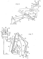
- Fig. 1
- eine Seitenansicht eines Tieflöffelbaggers,
- Fig. 2
- eine schematische Darstellung eines Systems zur Detektion der Orientierung und zur automatischen Steuerung einer Schaufel eines Laders und
- Fig. 3
- eine schematische Darstellung eines Systems zur Detektion der Orientierung und zur automatischen Steuerung einer Schaufel eines Tieflöffels.
Claims (21)
- Arbeitsfahrzeug, mit einem Rahmen (12), einer Bewegungseinheit (22; 64, 66), einem Werkzeug (24; 68), einem Werkzeugaktuator (38; 69), einem Winkelgeschwindigkeitssensor (54; 112) und einer Steuereinheit (50), wobei die Bewegungseinheit (22; 64, 66) ein erstes Ende (26; 76) und ein zweites Ende (30; 86) aufweist, wobei das erste Ende (26; 76) an dem Rahmen (12) angebracht ist, wobei das Werkzeug (24; 68) um eine Achse (32; 88) drehbar/schwenkbar an dem zweiten Ende (30; 86) der Bewegungseinheit (22; 94, 66) angebracht und zur Verrichtung einer Arbeitsfunktion vorgesehen ist, wobei der Werkzeugaktuator (38; 96) an dem Werkzeug (24; 68) angebracht und ausgebildet ist, das Werkzeug (24; 68) als Reaktion auf ein Werkzeugsteuersignal (52; 110) um die Achse (32; 88) kontrollierbar zu bewegen, wobei der Winkelgeschwindigkeitssensor (54; 112) dem Werkzeug (24; 68) zugeordnet und ausgebildet ist, die Winkelgeschwindigkeit des Werkzeugs (24; 68) zu detektieren und kontinuierlich ein Winkelgeschwindigkeitssignal (56; 114) zu generieren, wobei die Steuereinheit (50) rechnerische, Speicher- und/oder Echtzeitfähigkeiten aufweist und mit dem Werkzeugaktuator (38; 69) und dem Winkelgeschwindigkeitssensor (54; 112) in Verbindung steht, und wobei die Steuereinheit (50) ausgebildet ist, ein Werkzeugsteuersignal (52; 110) zu generieren, um kontinuierlich eine vorgebbare bzw. gewünschte Werkzeugwinkelgeschwindigkeit als Reaktion auf das Winkelgeschwindigkeitssignal (56; 114) zu erzielen.
- Arbeitsfahrzeug nach Anspruch 1, wobei die Bewegungseinheit (22; 64, 66) einen Ausleger (22) mit einem ersten Ende (26) und einem zweiten Ende (30) aufweist, und wobei das erste Ende (26) - vorzugsweise um eine Auslegerachse (28) drehbar/schwenkbar - an dem Rahmen (12) angebracht ist.
- Arbeitsgerät nach Anspruch 1 oder 2, wobei eine mit der Steuereinheit (50) in Verbindung stehende Werkzeugkommandoeingabeeinheit (44; 102) vorgesehen und ausgebildet ist, ein Werkzeugkommandosignal (48; 108) als Reaktion einer einer gewünschten Werkzeugbewegung entsprechenden Betätigung durch einen Bediener zu generieren, wobei die Steuereinheit (50) ausgebildet ist, das Werkzeugkommandosignal (48; 108) zu empfangen und als Reaktion hierauf ein Werkzeugsteuersignal (52; 110) zu generieren, um eine vorgebbare bzw. gewünschte Werkzeugbewegung zu erzielen und wobei die Steuereinheit (50) ausgebildet ist, nicht mehr auf das Winkelgeschwindigkeitssignal (56; 114) zu regieren, um eine vorgebbare bzw. gewünschte Werkzeugwinkelgeschwindigkeit zu erzielen, während das Werkzeugkontrollsignal (48; 108) empfangen wird.
- Arbeitsfahrzeug nach Anspruch 3, wobei die vorgebbare bzw. gewünschte Winkelgeschwindigkeit Null ist, wodurch eine anfängliche Werkzeugorientierung im Wesentlichen beibehaltbar ist.
- Arbeitsfahrzeug nach Anspruch 3 oder 4, wobei die anfängliche Werkzeugorientierung im Wesentlichen der Orientierung des Werkzeugs (24; 68) entspricht, die vorliegt, wenn die Werkzeugkommandoeingabeeinheit (44; 102) kein Werkzeugkommandosignal (48; 108) mehr generiert.
- Arbeitsfahrzeug nach einem der Ansprüche 1 bis 5, wobei ein Werkzeugbeibehaltungskommandoschalter (58; 116) vorgesehen ist, welcher mit der Steuereinheit (50) in Verbindung steht und welcher ausgebildet ist, ein Werkzeugbeibehaltungskommandosignal (60; 118) als Reaktion auf eine Betätigung des Bedieners zu generieren, und wobei die Steuereinheit (50) ausgebildet ist, das Werkzeugbeibehaltungskommandosignal (60; 118) zu empfangen und das Winkelgeschwindigkeitssignal (56; 114) zu ignorieren, wenn nicht das Werkzeugbeibehaltungskommandosignal (60; 118) empfangen wird.
- Arbeitsfahrzeug nach einem der Ansprüche 1 bis 6, wobei die Steuereinheit (50) ausgebildet ist, das Winkelgeschwindigkeitssignal (56; 114) als Funktion der Zeit zu integrieren, um eine Abweichung einer anfänglichen Werkzeugorientierung zu berechnen und ein Werkzeugsteuersignal (52; 110) zu generieren, um eine vorgebbare bzw. gewünschte Abweichung des Werkzeugs zu erzielen, wobei die Steuereinheit (50) ausgebildet ist, nicht mehr auf das Winkelgeschwindigkeitssignal (56; 114) zu regieren, um die vorgebbare bzw. gewünschte Werkzeugwinkelgeschwindigkeit zu erzielen, um die vorgebbare bzw. gewünschte Abweichung des Werkzeugs zu erzielen, und wobei vorzugsweise die vorgebbare bzw. gewünschte Abweichung des Werkzeugs im Wesentlichen Null ist.
- Arbeitsfahrzeug nach einem der Ansprüche 1 bis 7, wobei die Steuereinheit (50) ausgebildet ist, nicht mehr auf das Winkelgeschwindigkeitssignal (56; 114) zu regieren, um die vorgegebene bzw. gewünschte Werkzeugwinkelgeschwindigkeit und die vorgegebene bzw. gewünschte Abweichung des Werkzeugs zu erzielen, während die Steuereinheit (50) das Werkzeugkommandosignal (48; 108) empfängt.
- Arbeitsfahrzeug nach Anspruch 8, wobei die vorgebbare bzw. gewünschte Abweichung des Werkzeugs im Wesentlichen Null ist, wodurch die anfängliche Werkzeugorientierung im Wesentlichen beibehaltbar ist.
- Arbeitsfahrzeug nach einem der Ansprüche 2 bis 9, wobei das erste Ende (26) des Auslegers (22) um eine Achse (28) drehbar/schwenkbar an dem Rahmen (12) angebracht ist, wobei das Arbeitsfahrzeug (10) einen Auslegeraktuator (36) aufweist, welcher an dem Ausleger (22) und an den Rahmen (12) angebracht ist, und wobei der Auslegeraktuator (36) ausgebildet ist, den Ausleger (22) um die Achse (28) kontrollierbar zu bewegen.
- Arbeitsfahrzeug Anspruch 10, wobei sowohl der Werkzeugaktuator (38) als auch der Auslegeraktuator (36) jeweils einen oder mehrere Hydraulikzylinder (36, 40) und einen entsprechenden elektronisch angesteuerten Hydraulikkreis (42) aufweisen.
- Arbeitsfahrzeug nach einem der Ansprüche 1 bis 11, wobei das Werkzeug in Form einer Laderschaufel (24) ausgeführt ist und/oder wobei das Arbeitsfahrzeug (10) in Form eines Laders und/oder in Form eines Tieflöffelbaggers ausgeführt ist.
- Arbeitsfahrzeug nach Anspruch 12, wobei ein Laderschaufelaktuator (38) einen Hydraulikzylinder (40) und einen elektronisch ansteuerbaren Hydraulikreis (42) umfasst, wobei der Hydraulikzylinder (40) zwischen dem Ausleger (22) und der Laderschaufel (24) angeordnet ist, wobei der Laderschaufelaktuator (38) ausgebildet ist, die Laderschaufel (24) um die Achse (32) als Reaktion auf ein Laderschaufelkommandosignal (48) kontrollierbar zu bewegen, wobei ein Auslegeraktuator einen Hydraulikzylinder (36) aufweist, welcher zwischen dem Rahmen (12) und dem Ausleger (22) angeordnet ist, wobei der Auslegeraktuator ausgebildet ist, den Ausleger (22) um die Achse (28) kontrollierbar zu bewegen, wobei eine Steuereinheit (50) mit der Laderschaufelkommandoeingabeeinheit (44) in Verbindung steht und ausgebildet ist, ein Laderschaufelsteuersignal (52) zu erzeugen, um eine gewünschte Laderschaufelbewegung als Reaktion auf das Laderschaufelkommandosignal (48) zu erzielen, und wobei die Steuereinheit (50) ausgebildet ist, ein Laderschaufelsteuersignal (52) zu erzeugen, um kontinuierlich eine gewünschte Laderschaufelwinkelgeschwindigkeit als Redaktion auf das Winkelgeschwindigkeitssignal (56) zu erzielen, wenn kein Laderschaufelkommandosignal (48) empfangen wird.
- Arbeitsfahrzeug nach einem der Ansprüche 1 bis 13, wobei die Bewegungseinheit (22; 64, 66) einen Ausleger (64) und einen Löffelstiel (66) aufweist, wobei der Ausleger (64) ein erstes Ende (67) und ein zweites Ende (80) aufweist, wobei das erste Ende (76) - vorzugsweise drehbar/schwenkbar um eine Achse (78) - an dem Rahmen (12) angeordnet ist, wobei der Löffelstiel (66) ein erstes Ende (82) und ein zweites Ende (86) aufweist, und wobei das erste Ende (82) um die Achse (84) drehbar/schwenkbar an dem Ausleger (64) angebracht ist.
- Arbeitsfahrzeug nach Anspruch 14, wobei ein Werkzeugaktuator (96) vorgesehen ist, welcher einen Hydraulikzylinder (98) und einen elektronisch ansteuerbaren Hydraulikkreis (100) aufweist, und wobei der Hydraulikzylinder (98) zwischen dem Löffelstiel (66) und dem Werkzeug (68) angebracht ist.
- Arbeitsfahrzeug nach Anspruch 14 oder 15, wobei ein Auslegeraktuator einen Hydraulikzylinder (92) aufweist, welcher zwischen dem Rahmen (12) und dem Ausleger (64) angebracht ist, und wobei der Auslegeraktuator ausgebildet ist, den Ausleger (64) um die Achse (78) kontrollierbar zu bewegen.
- Arbeitsfahrzeug nach einem der Ansprüche 14 bis 16, wobei ein Löffelstielaktuator einen Hydraulikzylinder (94) aufweist, welcher zwischen dem Ausleger (64) und dem Löffelstiel (66) angebracht ist, und wobei der Löffelstielaktuator ausgebildet ist, den Löffelstiel (66) um die Achse (84) kontrollierbar zu bewegen.
- Arbeitsfahrzeug nach einem der Ansprüche 14 bis 17, wobei eine Werkzeugkommandoeingabeeinheit (102) mit der Steuereinheit (50) in Verbindung steht und ausgebildet ist, ein Werkzeugkommandosignal (108) als Reaktion auf eine einer gewünschten Werkzeugbewegung entsprechenden Betätigung eines Bedieners zu erzeugen.
- Arbeitsfahrzeug nach einem der Ansprüche 14 bis 18, wobei eine Steuereinheit (50) mit der Werkzeugkommandoeingabeeinheit (102) in Verbindung steht und ausgebildet ist, ein Werkzeugsteuersignal (110) zu erzeugen, um eine vorgebbare bzw. gewünschte Werkzeugbewegung als Reaktion auf das Werkzeugkommandosignal (108) zu erzielen, und wobei die Steuereinheit (50) ausgebildet ist, ein Werkzeugsteuersignal (110) zu generieren, um kontinuierlich eine vorgebbare/gewünschte Werkzeugwinkelgeschwindigkeit als Reaktion auf das Winkelgeschwindigkeitssignal (114) zu erzielen, wenn kein Werkzeugkommandosignal (108) empfangen wird.
- Arbeitsfahrzeug nach einem der Ansprüche 14 bis 19, wobei eine Auslegerkommandoeingabeeinheit (106) vorgesehen ist, welche mit der Steuereinheit (50) in Verbindung steht und ausgebildet ist, ein Auslegerkommandosignal (122) als Reaktion auf eine einer gewünschten Auslegerbewegung entsprechenden Betätigung eines Bedieners zu erzeugen, wobei die Steuereinheit (50) ausgebildet ist, das Winkelgeschwindigkeitssignal (114) zu ignorieren, wenn nicht das Auslegerkommandosignal (122) empfangen wird, wobei das Arbeitsfahrzeug (10) eine Löffelstielkommandoeingabeeinheit (104) aufweist, welche mit der Steuereinheit (50) in Verbindung steht und ausgebildet ist, ein Löffelstielkommandosignal (120) als Reaktion auf eine einer gewünschten Löffelstielbewegung entsprechenden Betätigung eines Bedieners zu generieren, und wobei die Steuereinheit (50) ausgebildet ist, das Winkelgeschwindigkeitssignal (114) zu ignorieren, wenn nicht ein Löffelstielkommandosignal (120) empfangen wird.
- Arbeitsfahrzeug nach einem der Ansprüche 14 bis 20, wobei der Rahmen (12) einen schwenkbaren Rahmen (62) und eine Aktuator für den schwenkbaren Rahmen (62) aufweist, wobei das erste Ende (76) des Auslegers (64) an dem schwenkbaren Rahmen (62) drehbar/schwenkbar angebracht ist, und wobei der Aktuator für den schwenkbaren Rahmen (62) einen Hydraulikzylinder (90) aufweist, welcher ausgebildet ist, den schwenkbaren Rahmen (62) um eine Achse (72) kontrollierbar zu bewegen.
Applications Claiming Priority (4)
| Application Number | Priority Date | Filing Date | Title |
|---|---|---|---|
| US285733 | 1988-12-16 | ||
| US10/285,733 US6609315B1 (en) | 2002-10-31 | 2002-10-31 | Automatic backhoe tool orientation control |
| US285732 | 2002-10-31 | ||
| US10/285,732 US6763619B2 (en) | 2002-10-31 | 2002-10-31 | Automatic loader bucket orientation control |
Publications (2)
| Publication Number | Publication Date |
|---|---|
| EP1416095A1 true EP1416095A1 (de) | 2004-05-06 |
| EP1416095B1 EP1416095B1 (de) | 2011-10-12 |
Family
ID=32095694
Family Applications (1)
| Application Number | Title | Priority Date | Filing Date |
|---|---|---|---|
| EP03024734A Expired - Lifetime EP1416095B1 (de) | 2002-10-31 | 2003-10-29 | Arbeitsfahrzeug, insbesondere ein Tieflöffelbagger und/oder ein Fahrzeug mit einem Frontlader |
Country Status (2)
| Country | Link |
|---|---|
| EP (1) | EP1416095B1 (de) |
| AT (1) | ATE528446T1 (de) |
Cited By (5)
| Publication number | Priority date | Publication date | Assignee | Title |
|---|---|---|---|---|
| WO2010121713A1 (de) * | 2009-04-20 | 2010-10-28 | Robert Bosch Gmbh | Mobile arbeitsmaschine mit einer positionsregeleinrichtung eines arbeitsarms und verfahren zur positionsregelung eines arbeitsarms einer mobilen arbeitsmaschine |
| EP3007553B1 (de) | 2013-09-18 | 2017-03-01 | HORSCH LEEB Application Systems GmbH | Vorrichtung zum ausbringen von flüssigen und/oder festen wirkstoffen und verfahren zur steuerung einer solchen vorrichtung |
| US10244747B2 (en) | 2013-11-10 | 2019-04-02 | Horsch Leeb Application Systems Gmbh | Apparatus and method for discharging liquid and/or solid active substances |
| US10561061B2 (en) | 2015-03-02 | 2020-02-18 | Horsch Leeb Application Systems Gmbh | Device for spreading liquid and/or solid active agents and method for controlling such a device |
| US20230074375A1 (en) * | 2020-04-17 | 2023-03-09 | Komatsu Ltd. | Control system and control method |
Citations (8)
| Publication number | Priority date | Publication date | Assignee | Title |
|---|---|---|---|---|
| JPS56150229A (en) * | 1980-04-24 | 1981-11-20 | Hitachi Constr Mach Co Ltd | Control of bucket angle of oil-pressure shovel, etc. |
| JPS56150230A (en) * | 1980-04-23 | 1981-11-20 | Hitachi Constr Mach Co Ltd | Control of angle of bucket of oil-pressure shovel, etc. |
| JPS5820835A (ja) * | 1981-07-31 | 1983-02-07 | Hitachi Constr Mach Co Ltd | 腕式作業機のバケツト角制御装置 |
| JPS5826128A (ja) * | 1981-08-11 | 1983-02-16 | Hitachi Constr Mach Co Ltd | 腕式作業機のバケツト角制御方法 |
| JPS60133127A (ja) * | 1983-12-22 | 1985-07-16 | Hitachi Constr Mach Co Ltd | ロ−デイングシヨベルのバケツト角制御方法 |
| US5383390A (en) * | 1993-06-28 | 1995-01-24 | Caterpillar Inc. | Multi-variable control of multi-degree of freedom linkages |
| US5748097A (en) * | 1997-02-28 | 1998-05-05 | Case Corporation | Method and apparatus for storing the boom of a work vehicle |
| US6233511B1 (en) * | 1997-11-26 | 2001-05-15 | Case Corporation | Electronic control for a two-axis work implement |
-
2003
- 2003-10-29 AT AT03024734T patent/ATE528446T1/de active
- 2003-10-29 EP EP03024734A patent/EP1416095B1/de not_active Expired - Lifetime
Patent Citations (8)
| Publication number | Priority date | Publication date | Assignee | Title |
|---|---|---|---|---|
| JPS56150230A (en) * | 1980-04-23 | 1981-11-20 | Hitachi Constr Mach Co Ltd | Control of angle of bucket of oil-pressure shovel, etc. |
| JPS56150229A (en) * | 1980-04-24 | 1981-11-20 | Hitachi Constr Mach Co Ltd | Control of bucket angle of oil-pressure shovel, etc. |
| JPS5820835A (ja) * | 1981-07-31 | 1983-02-07 | Hitachi Constr Mach Co Ltd | 腕式作業機のバケツト角制御装置 |
| JPS5826128A (ja) * | 1981-08-11 | 1983-02-16 | Hitachi Constr Mach Co Ltd | 腕式作業機のバケツト角制御方法 |
| JPS60133127A (ja) * | 1983-12-22 | 1985-07-16 | Hitachi Constr Mach Co Ltd | ロ−デイングシヨベルのバケツト角制御方法 |
| US5383390A (en) * | 1993-06-28 | 1995-01-24 | Caterpillar Inc. | Multi-variable control of multi-degree of freedom linkages |
| US5748097A (en) * | 1997-02-28 | 1998-05-05 | Case Corporation | Method and apparatus for storing the boom of a work vehicle |
| US6233511B1 (en) * | 1997-11-26 | 2001-05-15 | Case Corporation | Electronic control for a two-axis work implement |
Non-Patent Citations (4)
| Title |
|---|
| PATENT ABSTRACTS OF JAPAN vol. 006, no. 033 (M - 114) 27 February 1982 (1982-02-27) * |
| PATENT ABSTRACTS OF JAPAN vol. 007, no. 098 (M - 210) 26 April 1983 (1983-04-26) * |
| PATENT ABSTRACTS OF JAPAN vol. 007, no. 104 (M - 212) 6 May 1983 (1983-05-06) * |
| PATENT ABSTRACTS OF JAPAN vol. 009, no. 294 (M - 431) 20 November 1985 (1985-11-20) * |
Cited By (9)
| Publication number | Priority date | Publication date | Assignee | Title |
|---|---|---|---|---|
| WO2010121713A1 (de) * | 2009-04-20 | 2010-10-28 | Robert Bosch Gmbh | Mobile arbeitsmaschine mit einer positionsregeleinrichtung eines arbeitsarms und verfahren zur positionsregelung eines arbeitsarms einer mobilen arbeitsmaschine |
| US9151013B2 (en) | 2009-04-20 | 2015-10-06 | Robert Bosch Gmbh | Mobile working machine comprising a position control device of a working arm, and method for controlling the position of a working arm of a mobile working machine |
| EP3007553B1 (de) | 2013-09-18 | 2017-03-01 | HORSCH LEEB Application Systems GmbH | Vorrichtung zum ausbringen von flüssigen und/oder festen wirkstoffen und verfahren zur steuerung einer solchen vorrichtung |
| EP3183963B1 (de) | 2013-09-18 | 2018-05-16 | HORSCH LEEB Application Systems GmbH | Vorrichtung zum ausbringen von flüssigen und/oder festen wirkstoffen und verfahren zur steuerung einer solchen vorrichtung |
| US10470361B2 (en) | 2013-09-18 | 2019-11-12 | Horsch Leeb Application Systems Gmbh | Device for discharging fluid and/or solid active materials and method for controlling such a device |
| US10244747B2 (en) | 2013-11-10 | 2019-04-02 | Horsch Leeb Application Systems Gmbh | Apparatus and method for discharging liquid and/or solid active substances |
| US10561061B2 (en) | 2015-03-02 | 2020-02-18 | Horsch Leeb Application Systems Gmbh | Device for spreading liquid and/or solid active agents and method for controlling such a device |
| US20230074375A1 (en) * | 2020-04-17 | 2023-03-09 | Komatsu Ltd. | Control system and control method |
| US12188200B2 (en) * | 2020-04-17 | 2025-01-07 | Komatsu Ltd. | Control system and control method |
Also Published As
| Publication number | Publication date |
|---|---|
| EP1416095B1 (de) | 2011-10-12 |
| ATE528446T1 (de) | 2011-10-15 |
Similar Documents
| Publication | Publication Date | Title |
|---|---|---|
| EP1467031B1 (de) | Tieflöffelbagger mit einem teleskopierbaren Löffelstiel | |
| DE112019003881B4 (de) | Steuervorrichtung und steuerverfahren für lademaschinen | |
| DE112012000111B4 (de) | Vorrichtung zur Anzeige eines möglichen Arbeitsbereichs in einem Hydraulikbagger und Verfahren zur Steuerung derselben | |
| DE112014000142B4 (de) | Baufahrzeug | |
| DE112016000013B4 (de) | Steuersystem für ein Arbeitsfahrzeug, Steuerverfahren und Arbeitsfahrzeug | |
| DE112014000077B4 (de) | Steuersystem für eine Baumaschine, Baumaschine und Verfahren zum Steuern einer Baumaschine | |
| EP2042276B1 (de) | Landwirtschaftliche Maschine und Verfahren zur Positionsbestimmung | |
| DE112014000075B4 (de) | Steuersystem für Erdbewegungsmaschine und Erdbewegungsmaschine | |
| EP2843378B1 (de) | Arbeitsmaschine mit Hubvorrichtung und Wiegeeinrichtung | |
| DE112016000070B4 (de) | Arbeitsmaschinensteuersystem, arbeitsmaschine und arbeitsmaschinensteuerverfahren | |
| DE112019003932T5 (de) | Arbeitsmaschine, steuervorrichtung und steuerverfahren | |
| DE112017002603B4 (de) | Steuerungssystem für eine baumaschine, baumaschine und steuerverfahren für eine baumaschine | |
| DE112015000241B4 (de) | Arbeitsfahrzeuge und Verfahren zum Erfassen des Kippwinkels | |
| DE112015000055T5 (de) | Steuersystem einer Arbeitsmaschine und Arbeitsmaschine | |
| DE112016000072T5 (de) | Baumaschinensteuersystem, baumaschine und baumaschinensteuerverfahren | |
| DE112019003156T5 (de) | Steuervorrichtung und steuerverfahren für eine arbeitsmaschine | |
| EP1650358A2 (de) | Steuersystem zur koordinierten Steuerung des Auslegers an einem Arbeitsfahrzeug | |
| DE112016000156T5 (de) | Steuervorrichtung für eine Baumaschine und Verfahren zur Steuerung einer Baumaschine | |
| DE112018000695T5 (de) | Baumaschine und Verfahren zur Steuerung derselben | |
| EP3440273A1 (de) | Verfahren zur steuerung der bewegung eines gelenkschlauchträgers eines saugbaggers | |
| DE102021202515A1 (de) | Vorrichtung und verfahren für einen bagger | |
| DE112020000308T5 (de) | Steuersystem für baumaschinen, baumaschine und steuerverfahren für baumaschinen | |
| DE112021003917T5 (de) | Beladearbeit-unterstützungssystem | |
| EP1516850B1 (de) | Sensoreinrichtung, Stelleinrichtung und Arbeitsgerät | |
| EP1416095B1 (de) | Arbeitsfahrzeug, insbesondere ein Tieflöffelbagger und/oder ein Fahrzeug mit einem Frontlader |
Legal Events
| Date | Code | Title | Description |
|---|---|---|---|
| PUAI | Public reference made under article 153(3) epc to a published international application that has entered the european phase |
Free format text: ORIGINAL CODE: 0009012 |
|
| AK | Designated contracting states |
Kind code of ref document: A1 Designated state(s): AT BE BG CH CY CZ DE DK EE ES FI FR GB GR HU IE IT LI LU MC NL PT RO SE SI SK TR |
|
| AX | Request for extension of the european patent |
Extension state: AL LT LV MK |
|
| 17P | Request for examination filed |
Effective date: 20041108 |
|
| AKX | Designation fees paid |
Designated state(s): AT BE BG CH CY CZ DE DK EE ES FI FR GB GR HU IE IT LI LU MC NL PT RO SE SI SK TR |
|
| GRAP | Despatch of communication of intention to grant a patent |
Free format text: ORIGINAL CODE: EPIDOSNIGR1 |
|
| GRAS | Grant fee paid |
Free format text: ORIGINAL CODE: EPIDOSNIGR3 |
|
| GRAA | (expected) grant |
Free format text: ORIGINAL CODE: 0009210 |
|
| AK | Designated contracting states |
Kind code of ref document: B1 Designated state(s): AT BE BG CH CY CZ DE DK EE ES FI FR GB GR HU IE IT LI LU MC NL PT RO SE SI SK TR |
|
| REG | Reference to a national code |
Ref country code: GB Ref legal event code: FG4D Free format text: NOT ENGLISH |
|
| REG | Reference to a national code |
Ref country code: CH Ref legal event code: EP |
|
| REG | Reference to a national code |
Ref country code: IE Ref legal event code: FG4D |
|
| REG | Reference to a national code |
Ref country code: DE Ref legal event code: R096 Ref document number: 50314003 Country of ref document: DE Effective date: 20111208 |
|
| REG | Reference to a national code |
Ref country code: NL Ref legal event code: VDEP Effective date: 20111012 |
|
| BERE | Be: lapsed |
Owner name: DEERE & CY Effective date: 20111031 |
|
| REG | Reference to a national code |
Ref country code: IE Ref legal event code: FD4D |
|
| PG25 | Lapsed in a contracting state [announced via postgrant information from national office to epo] |
Ref country code: NL Free format text: LAPSE BECAUSE OF FAILURE TO SUBMIT A TRANSLATION OF THE DESCRIPTION OR TO PAY THE FEE WITHIN THE PRESCRIBED TIME-LIMIT Effective date: 20111012 Ref country code: GR Free format text: LAPSE BECAUSE OF FAILURE TO SUBMIT A TRANSLATION OF THE DESCRIPTION OR TO PAY THE FEE WITHIN THE PRESCRIBED TIME-LIMIT Effective date: 20120113 Ref country code: SE Free format text: LAPSE BECAUSE OF FAILURE TO SUBMIT A TRANSLATION OF THE DESCRIPTION OR TO PAY THE FEE WITHIN THE PRESCRIBED TIME-LIMIT Effective date: 20111012 Ref country code: SI Free format text: LAPSE BECAUSE OF FAILURE TO SUBMIT A TRANSLATION OF THE DESCRIPTION OR TO PAY THE FEE WITHIN THE PRESCRIBED TIME-LIMIT Effective date: 20111012 Ref country code: MC Free format text: LAPSE BECAUSE OF NON-PAYMENT OF DUE FEES Effective date: 20111031 Ref country code: PT Free format text: LAPSE BECAUSE OF FAILURE TO SUBMIT A TRANSLATION OF THE DESCRIPTION OR TO PAY THE FEE WITHIN THE PRESCRIBED TIME-LIMIT Effective date: 20120213 |
|
| REG | Reference to a national code |
Ref country code: CH Ref legal event code: PL |
|
| PG25 | Lapsed in a contracting state [announced via postgrant information from national office to epo] |
Ref country code: CY Free format text: LAPSE BECAUSE OF FAILURE TO SUBMIT A TRANSLATION OF THE DESCRIPTION OR TO PAY THE FEE WITHIN THE PRESCRIBED TIME-LIMIT Effective date: 20111012 |
|
| PG25 | Lapsed in a contracting state [announced via postgrant information from national office to epo] |
Ref country code: DK Free format text: LAPSE BECAUSE OF FAILURE TO SUBMIT A TRANSLATION OF THE DESCRIPTION OR TO PAY THE FEE WITHIN THE PRESCRIBED TIME-LIMIT Effective date: 20111012 Ref country code: IE Free format text: LAPSE BECAUSE OF FAILURE TO SUBMIT A TRANSLATION OF THE DESCRIPTION OR TO PAY THE FEE WITHIN THE PRESCRIBED TIME-LIMIT Effective date: 20111012 Ref country code: BE Free format text: LAPSE BECAUSE OF NON-PAYMENT OF DUE FEES Effective date: 20111031 Ref country code: EE Free format text: LAPSE BECAUSE OF FAILURE TO SUBMIT A TRANSLATION OF THE DESCRIPTION OR TO PAY THE FEE WITHIN THE PRESCRIBED TIME-LIMIT Effective date: 20111012 Ref country code: LI Free format text: LAPSE BECAUSE OF NON-PAYMENT OF DUE FEES Effective date: 20111031 Ref country code: CH Free format text: LAPSE BECAUSE OF NON-PAYMENT OF DUE FEES Effective date: 20111031 Ref country code: BG Free format text: LAPSE BECAUSE OF FAILURE TO SUBMIT A TRANSLATION OF THE DESCRIPTION OR TO PAY THE FEE WITHIN THE PRESCRIBED TIME-LIMIT Effective date: 20120112 Ref country code: SK Free format text: LAPSE BECAUSE OF FAILURE TO SUBMIT A TRANSLATION OF THE DESCRIPTION OR TO PAY THE FEE WITHIN THE PRESCRIBED TIME-LIMIT Effective date: 20111012 Ref country code: CZ Free format text: LAPSE BECAUSE OF FAILURE TO SUBMIT A TRANSLATION OF THE DESCRIPTION OR TO PAY THE FEE WITHIN THE PRESCRIBED TIME-LIMIT Effective date: 20111012 |
|
| PLBE | No opposition filed within time limit |
Free format text: ORIGINAL CODE: 0009261 |
|
| STAA | Information on the status of an ep patent application or granted ep patent |
Free format text: STATUS: NO OPPOSITION FILED WITHIN TIME LIMIT |
|
| PG25 | Lapsed in a contracting state [announced via postgrant information from national office to epo] |
Ref country code: RO Free format text: LAPSE BECAUSE OF FAILURE TO SUBMIT A TRANSLATION OF THE DESCRIPTION OR TO PAY THE FEE WITHIN THE PRESCRIBED TIME-LIMIT Effective date: 20111012 |
|
| 26N | No opposition filed |
Effective date: 20120713 |
|
| REG | Reference to a national code |
Ref country code: DE Ref legal event code: R097 Ref document number: 50314003 Country of ref document: DE Effective date: 20120713 |
|
| REG | Reference to a national code |
Ref country code: AT Ref legal event code: MM01 Ref document number: 528446 Country of ref document: AT Kind code of ref document: T Effective date: 20111029 |
|
| PG25 | Lapsed in a contracting state [announced via postgrant information from national office to epo] |
Ref country code: AT Free format text: LAPSE BECAUSE OF NON-PAYMENT OF DUE FEES Effective date: 20111029 |
|
| PG25 | Lapsed in a contracting state [announced via postgrant information from national office to epo] |
Ref country code: ES Free format text: LAPSE BECAUSE OF FAILURE TO SUBMIT A TRANSLATION OF THE DESCRIPTION OR TO PAY THE FEE WITHIN THE PRESCRIBED TIME-LIMIT Effective date: 20120123 |
|
| PG25 | Lapsed in a contracting state [announced via postgrant information from national office to epo] |
Ref country code: LU Free format text: LAPSE BECAUSE OF NON-PAYMENT OF DUE FEES Effective date: 20111029 |
|
| PG25 | Lapsed in a contracting state [announced via postgrant information from national office to epo] |
Ref country code: FI Free format text: LAPSE BECAUSE OF FAILURE TO SUBMIT A TRANSLATION OF THE DESCRIPTION OR TO PAY THE FEE WITHIN THE PRESCRIBED TIME-LIMIT Effective date: 20111012 |
|
| PG25 | Lapsed in a contracting state [announced via postgrant information from national office to epo] |
Ref country code: TR Free format text: LAPSE BECAUSE OF FAILURE TO SUBMIT A TRANSLATION OF THE DESCRIPTION OR TO PAY THE FEE WITHIN THE PRESCRIBED TIME-LIMIT Effective date: 20111012 |
|
| PG25 | Lapsed in a contracting state [announced via postgrant information from national office to epo] |
Ref country code: HU Free format text: LAPSE BECAUSE OF FAILURE TO SUBMIT A TRANSLATION OF THE DESCRIPTION OR TO PAY THE FEE WITHIN THE PRESCRIBED TIME-LIMIT Effective date: 20111012 |
|
| PGFP | Annual fee paid to national office [announced via postgrant information from national office to epo] |
Ref country code: FR Payment date: 20131017 Year of fee payment: 11 Ref country code: DE Payment date: 20130919 Year of fee payment: 11 |
|
| PGFP | Annual fee paid to national office [announced via postgrant information from national office to epo] |
Ref country code: IT Payment date: 20131024 Year of fee payment: 11 |
|
| REG | Reference to a national code |
Ref country code: DE Ref legal event code: R119 Ref document number: 50314003 Country of ref document: DE |
|
| PG25 | Lapsed in a contracting state [announced via postgrant information from national office to epo] |
Ref country code: DE Free format text: LAPSE BECAUSE OF NON-PAYMENT OF DUE FEES Effective date: 20150501 |
|
| REG | Reference to a national code |
Ref country code: FR Ref legal event code: ST Effective date: 20150630 |
|
| PG25 | Lapsed in a contracting state [announced via postgrant information from national office to epo] |
Ref country code: IT Free format text: LAPSE BECAUSE OF NON-PAYMENT OF DUE FEES Effective date: 20141029 Ref country code: FR Free format text: LAPSE BECAUSE OF NON-PAYMENT OF DUE FEES Effective date: 20141031 |
|
| PGFP | Annual fee paid to national office [announced via postgrant information from national office to epo] |
Ref country code: GB Payment date: 20191028 Year of fee payment: 17 |
|
| GBPC | Gb: european patent ceased through non-payment of renewal fee |
Effective date: 20201029 |
|
| PG25 | Lapsed in a contracting state [announced via postgrant information from national office to epo] |
Ref country code: GB Free format text: LAPSE BECAUSE OF NON-PAYMENT OF DUE FEES Effective date: 20201029 |