EP1416085A1 - Equipment for fabric guiding in a paper machine - Google Patents
Equipment for fabric guiding in a paper machine Download PDFInfo
- Publication number
- EP1416085A1 EP1416085A1 EP20030024347 EP03024347A EP1416085A1 EP 1416085 A1 EP1416085 A1 EP 1416085A1 EP 20030024347 EP20030024347 EP 20030024347 EP 03024347 A EP03024347 A EP 03024347A EP 1416085 A1 EP1416085 A1 EP 1416085A1
- Authority
- EP
- European Patent Office
- Prior art keywords
- equipment
- fabric
- stand
- roll
- edge detector
- Prior art date
- Legal status (The legal status is an assumption and is not a legal conclusion. Google has not performed a legal analysis and makes no representation as to the accuracy of the status listed.)
- Granted
Links
- 239000004744 fabric Substances 0.000 title claims abstract description 33
- 239000002184 metal Substances 0.000 claims abstract description 21
- 238000012546 transfer Methods 0.000 claims abstract description 17
- 238000010276 construction Methods 0.000 claims abstract description 15
- 230000002093 peripheral effect Effects 0.000 claims description 2
- 238000004519 manufacturing process Methods 0.000 description 13
- 238000005452 bending Methods 0.000 description 6
- 238000003466 welding Methods 0.000 description 3
- 238000003698 laser cutting Methods 0.000 description 2
- 238000003754 machining Methods 0.000 description 2
- 238000000034 method Methods 0.000 description 2
- 229910000831 Steel Inorganic materials 0.000 description 1
- 239000002253 acid Substances 0.000 description 1
- 238000010420 art technique Methods 0.000 description 1
- 238000005520 cutting process Methods 0.000 description 1
- 238000007688 edging Methods 0.000 description 1
- 230000000694 effects Effects 0.000 description 1
- 238000005304 joining Methods 0.000 description 1
- 238000012423 maintenance Methods 0.000 description 1
- 239000000463 material Substances 0.000 description 1
- 238000005259 measurement Methods 0.000 description 1
- NJPPVKZQTLUDBO-UHFFFAOYSA-N novaluron Chemical compound C1=C(Cl)C(OC(F)(F)C(OC(F)(F)F)F)=CC=C1NC(=O)NC(=O)C1=C(F)C=CC=C1F NJPPVKZQTLUDBO-UHFFFAOYSA-N 0.000 description 1
- 239000010959 steel Substances 0.000 description 1
- 238000012360 testing method Methods 0.000 description 1
Images


Classifications
-
- D—TEXTILES; PAPER
- D21—PAPER-MAKING; PRODUCTION OF CELLULOSE
- D21F—PAPER-MAKING MACHINES; METHODS OF PRODUCING PAPER THEREON
- D21F1/00—Wet end of machines for making continuous webs of paper
- D21F1/36—Guiding mechanisms
- D21F1/365—Guiding mechanisms for controlling the lateral position of the screen
Definitions
- the object of this invention is equipment for fabric guiding in a paper machine comprising at least one fabric arranged as an endless loop as well as rolls adapted to support it, for which rolls there is arranged, at the end of at least one of these rolls, equipment that includes
- the US patent No. 5,500,090 makes known equipment for fabric guiding in a paper machine.
- the edge detectors are placed after the roll, in the travel direction of the fabric, separated from the stand.
- sets of equipment are also known, in which the edge detectors are attached to the stand.
- the object of this invention is to provide novel equipment for fabric guiding in a paper machine, being simpler than heretofore, yet stronger and easier to manufacture.
- the features characterizing this invention become evident from the appended claims.
- the equipment according to the invention unexpectedly utilizes sheet metal in particular for the manufacture of the vertical brackets. Consequently, the final equipment is lighter in weight, yet more rigid than heretofore.
- the support structures of the equipment are easier and quicker to manufacture than heretofore while the dimensional accuracy is, however, better than known in the art.
- various constructions are additionally combined, which reduces the number of components and machining steps required in the production.
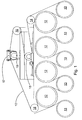
- Figure 1 shows the equipment according to the invention adapted in connection with a roll 17 supporting a paper machine fabric 10.
- the paper machine comprises at least one fabric arranged as an endless loop.
- the term paper machine is used here also in reference to a board machine or similar.
- the equipment is arranged to guide a dryer fabric, which passes via dryers 12, Vac rolls 13 and lead rolls 14 - 18.
- the equipment can be used to guide a press felt, for example, or another fabric used in a paper machine.
- the fabric generally there is arranged in connection with at least one roll end, equipment according to the invention.
- Today one paper production line includes as many as 20 guidable fabrics.
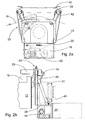
- FIGS 2a and 2b provide a more detailed illustration of the equipment according to the invention, including a stand 19 adapted to attach to the paper machine frame as well as a transfer base 20 movably adapted to the stand 19.
- the stand 19 is attached to the frame while the transfer base 20 is movable.
- Fabric guiding is provided by changing the position of the roll 17.
- the bearing pedestal 21 of the roll 17 is attached to the transfer base 20, which thus moves in the machine direction.
- the bearing assembly of the roll permits this movement, the range of which can be as long as 100 mm. In practice, a movement of a few millimetres is, however, sufficient for providing the desired guiding effect.
- Inside the stand 19 there is a suitable motor 22, from which the power is usually transmitted to the transfer base 20 by means of a gearing.
- the transfer base is movably attached to the stand using linear guides (not shown).
- the equipment further comprises at least one edge detector 23 for the roll 17, arranged on the opposite side of the fabric 10, which is used to determine the position of the fabric 10 in the axial direction of the roll 17.
- a non-contacting edge detector is used, but other types of edge detectors are also possible.
- the roll end supported by the equipment is set according to the edge detector, in which case the fabric position can be maintained as desired in the roll assembly.
- the electronic centre 24 is a separate unit located at the side of the stand 19 and can be turned aside during the maintenance of the motor, for example. This is illustrated by the rectangular depicted with broken lines in Figure 2b.
- the operation of the equipment according to the invention is thus fully independent, which gives more freedom than heretofore for its positioning in various positions.
- the stand 19 is provided with a vertical bracket 25.
- the stand 19 is provided with a nip guard 26 at the gaps formed by the roll 17 and the fabric 10, preventing, for example, introduction of hands in the said gaps.
- the vertical bracket and the nip guard are unexpectedly formed of an integrated sheet-metal construction. That is, the vertical bracket and the nip guard are of a one-piece construction, made of sheet metal. Consequently, the equipment is lighter in weight, yet more rigid than heretofore. Various fastening elements and supports are also needed less than heretofore.
- the production can be further simplified by forming the sheet-metal construction from one continuous sheet. This sheet-metal blank is shown in Figure 3. In practice, the thickness of sheet metal is 1 - 4, more preferably 2,5 - 3,5 mm. Due to the demanding operating conditions, it is additionally necessary to use acid-resistant steel. This sets special requirements also for the joining technique.
- the sheet-metal blank is additionally provided with perforations 27 enabling a manual bending.
- the sheet-metal blank Prior to the manual bending, the sheet-metal blank is provided with bends 28 at the points shown with dot-and-dash lines using an edging press, for example. In this case, the last bending can be made manually, thereby forming a box-type structure.
- suitable openings 29 are additionally cut in the sheet-metal blank, with the corresponding projections 30 arranged at the edges of the sheet blank. Consequently, the projections accurately guide manual bending to a correct point, thus providing a box-type structure shown in Figure 4a.
- the box-type structure is rigid, yet light in weight.
- the equipment comprises two vertical brackets of a box-type structure, in which case the construction becomes symmetric. Rigidity can be easily increased by a horizontal box-type structure 31 arranged between the upper parts of the vertical brackets ( Figure 4a). At the same time, the section remaining between the box-type structures forms the nip guard 26.
- the slide 37 is shown separated in Figures 4b and 4c, while in Figure 4a it is adapted in its position inside the box-type structure.
- the slide 37 is also made of sheet metal and there is additionally a nut 39 attached to it.
- the slide is operated with a threaded bar arranged through a horizontal box-type structure, at the end of which there is a suitable turning handle 40 ( Figure 2a). Consequently, the removal and attachment of edge detectors can take place quickly and safely without any tools.
- the fastening of a rigid and light sheet-metal construction to the stand is also easy. In the bottom part, the sheet-metal construction is fastened using two bolts, while in the upper part, a curved support 41 is used, inside which the cables 42 of the edge detector can be adapted.
Landscapes
- Paper (AREA)
- Treatment Of Fiber Materials (AREA)
- Telephone Function (AREA)
- Auxiliary Devices For And Details Of Packaging Control (AREA)
- Sewing Machines And Sewing (AREA)
- Registering, Tensioning, Guiding Webs, And Rollers Therefor (AREA)
Abstract
Description
- The object of this invention is equipment for fabric guiding in a paper machine comprising at least one fabric arranged as an endless loop as well as rolls adapted to support it, for which rolls there is arranged, at the end of at least one of these rolls, equipment that includes
- a stand adapted to attach to the paper machine frame,
- a nip guard in the stand at the gaps formed by the roll and the fabric,
- a transfer base movably adapted to the stand,
- transfer equipment for moving the transfer base in relation to the stand,
- at least one edge detector for the roll, arranged on the opposite side of the fabric for determining the fabric position, in the axial direction of the roll,
- a vertical bracket arranged in the stand for the edge detector, whereby the roll end supported with the equipment is adapted to be set according to the edge detector by means of the transfer equipment, for keeping a desired fabric position at the rolls.
- The US patent No. 5,500,090 makes known equipment for fabric guiding in a paper machine. In the equipment set forth the edge detectors are placed after the roll, in the travel direction of the fabric, separated from the stand. However, sets of equipment are also known, in which the edge detectors are attached to the stand.
- Independent of the location point, special vertical brackets are needed for supporting the edge detectors in an appropriate manner. Usually the vertical bracket is assembled from machined components, which are attached to the paper machine frame or to the said stand. In addition, a so-called nip guard is required at the equipment for preventing accidents.
- The production of a sufficiently rigid vertical bracket requires high material strengths. Consequently, several machining steps are needed in the production, and the final vertical bracket becomes heavy and expensive. In spite of the massive construction, in the practical use the vertical bracket vibrates as the roll rotates disturbing thus the operation of the edge detectors. Furthermore, the nip guard requires fastening elements of its own, which makes the total equipment complex and expensive to produce, yet sensitive to vibrations and difficult to locate in various positions.
- The object of this invention is to provide novel equipment for fabric guiding in a paper machine, being simpler than heretofore, yet stronger and easier to manufacture. The features characterizing this invention become evident from the appended claims. The equipment according to the invention unexpectedly utilizes sheet metal in particular for the manufacture of the vertical brackets. Consequently, the final equipment is lighter in weight, yet more rigid than heretofore. In addition, the support structures of the equipment are easier and quicker to manufacture than heretofore while the dimensional accuracy is, however, better than known in the art. In the equipment according to the invention various constructions are additionally combined, which reduces the number of components and machining steps required in the production.
- The invention is described below in detail by making reference to the enclosed drawings, which illustrate one of the embodiments of the invention, in which
- Figure 1
- is a side view of the equipment according to the invention adapted in connection with a roll in a dryer section of a paper machine;
- Figure 2a
- is a partial enlargement of Figure 1;
- Figure 2b
- is a machine-directional view of the equipment of Figure 2a;
- Figure 3
- shows the sheet metal blank for the vertical brackets of the equipment according to the invention;
- Figure 4a
- shows the assembly of the sheet metal blank of Figure 3;
- Figure 4b
- is a side view of the locking device according to the invention;
- Figure 4c
- is a front view of the locking device of Figure 4b.
- Figure 1 shows the equipment according to the invention adapted in connection with a
roll 17 supporting apaper machine fabric 10. The paper machine comprises at least one fabric arranged as an endless loop. The term paper machine is used here also in reference to a board machine or similar. In the embodiment of Figure 1 the equipment is arranged to guide a dryer fabric, which passes viadryers 12,Vac rolls 13 and lead rolls 14 - 18. In addition to the dryer fabric, the equipment can be used to guide a press felt, for example, or another fabric used in a paper machine. In connection with the fabric, generally there is arranged in connection with at least one roll end, equipment according to the invention. Today one paper production line includes as many as 20 guidable fabrics. - Figures 2a and 2b provide a more detailed illustration of the equipment according to the invention, including a
stand 19 adapted to attach to the paper machine frame as well as atransfer base 20 movably adapted to thestand 19. Here thestand 19 is attached to the frame while thetransfer base 20 is movable. Fabric guiding is provided by changing the position of theroll 17. In practice, thebearing pedestal 21 of theroll 17 is attached to thetransfer base 20, which thus moves in the machine direction. The bearing assembly of the roll permits this movement, the range of which can be as long as 100 mm. In practice, a movement of a few millimetres is, however, sufficient for providing the desired guiding effect. Inside thestand 19 there is asuitable motor 22, from which the power is usually transmitted to thetransfer base 20 by means of a gearing. Furthermore, the transfer base is movably attached to the stand using linear guides (not shown). - The fabric looping at a higher speed continuously moves in the lateral direction as well. Therefore, its guiding must also be continuous. That is, the roll end must be moved all the time to keep the fabric in the desired position. Therefore, the equipment further comprises at least one
edge detector 23 for theroll 17, arranged on the opposite side of thefabric 10, which is used to determine the position of thefabric 10 in the axial direction of theroll 17. In this application, a non-contacting edge detector is used, but other types of edge detectors are also possible. Preferably there is additionally sufficient amount of electronics in connection with the stand for the automation of the guiding system. In practice, the electronic system continuously compares the measurement results of the edge detector with the set values and, when required, moves the transfer base for the required distance by controlling the motor. Consequently, the roll end supported by the equipment is set according to the edge detector, in which case the fabric position can be maintained as desired in the roll assembly. Here theelectronic centre 24 is a separate unit located at the side of thestand 19 and can be turned aside during the maintenance of the motor, for example. This is illustrated by the rectangular depicted with broken lines in Figure 2b. The operation of the equipment according to the invention is thus fully independent, which gives more freedom than heretofore for its positioning in various positions. - For attaching the
edge detector 23, thestand 19 is provided with avertical bracket 25. In addition, thestand 19 is provided with anip guard 26 at the gaps formed by theroll 17 and thefabric 10, preventing, for example, introduction of hands in the said gaps. According to the invention the vertical bracket and the nip guard are unexpectedly formed of an integrated sheet-metal construction. That is, the vertical bracket and the nip guard are of a one-piece construction, made of sheet metal. Consequently, the equipment is lighter in weight, yet more rigid than heretofore. Various fastening elements and supports are also needed less than heretofore. The production can be further simplified by forming the sheet-metal construction from one continuous sheet. This sheet-metal blank is shown in Figure 3. In practice, the thickness of sheet metal is 1 - 4, more preferably 2,5 - 3,5 mm. Due to the demanding operating conditions, it is additionally necessary to use acid-resistant steel. This sets special requirements also for the joining technique. - Production problems are easily solved by using both laser cutting and laser welding in the production of the sheet metal according to the invention. In the cutting operation, the sheet-metal blank is additionally provided with
perforations 27 enabling a manual bending. Prior to the manual bending, the sheet-metal blank is provided withbends 28 at the points shown with dot-and-dash lines using an edging press, for example. In this case, the last bending can be made manually, thereby forming a box-type structure. To facilitate the manual bending and especially welding,suitable openings 29 are additionally cut in the sheet-metal blank, with the correspondingprojections 30 arranged at the edges of the sheet blank. Consequently, the projections accurately guide manual bending to a correct point, thus providing a box-type structure shown in Figure 4a. After bending, the above mentioned openings together with the projections are welded so as to form a smooth surface. Laser cutting and welding provide a strong and dimensionally accurate construction, which is additionally quick to manufacture. In practical tests it has been easy to achieve an accuracy of 0.1 mm, which is completely sufficient in this application. In addition, the box-type structure is rigid, yet light in weight. Preferably the equipment comprises two vertical brackets of a box-type structure, in which case the construction becomes symmetric. Rigidity can be easily increased by a horizontal box-type structure 31 arranged between the upper parts of the vertical brackets (Figure 4a). At the same time, the section remaining between the box-type structures forms thenip guard 26. - Separate vertical brackets known in the art have separate fastening elements for fastening the edge detectors. For a similar purpose, according to the invention, arranged in the
vertical bracket 25 of a box-type structure there are unexpectedly amere opening 32 and lockingdevices 33. Locking is provided with three support points 34 - 36, arranged at the edges of theopening 32, at uniform intervals in the peripheral direction. In practice, the edge detector is supported by six support points, three on each of the walls of the box-type structure. One of the support points on each wall is formed of the saidlocking devices 33 for fastening a cylinder-like edge detector. In addition, thelocking devices 33 comprise aslide 37 movably adapted in relation to theopening 32, with awedge surface 38 for fastening edge detectors of different diameters. Theslide 37 is shown separated in Figures 4b and 4c, while in Figure 4a it is adapted in its position inside the box-type structure. Theslide 37 is also made of sheet metal and there is additionally anut 39 attached to it. In this case the slide is operated with a threaded bar arranged through a horizontal box-type structure, at the end of which there is a suitable turning handle 40 (Figure 2a). Consequently, the removal and attachment of edge detectors can take place quickly and safely without any tools. The fastening of a rigid and light sheet-metal construction to the stand is also easy. In the bottom part, the sheet-metal construction is fastened using two bolts, while in the upper part, acurved support 41 is used, inside which thecables 42 of the edge detector can be adapted. - It has been possible to replace as many as 50 components, heretofore separate, with the construction of the equipment according to the invention. In addition, the construction is notably lighter in weight, yet more^rigid than heretofore. Furthermore, due to the sheet-metal technique, manufacturing of the construction is quick, and the final construction is dimensionally accurate. Even the complete equipment can be mounted in different locations and positions than what is shown in the example applications. Single type equipment can be used in different parts of a paper machine, while in the prior art technique different devices are often acquired for each production section.
Claims (7)
- Equipment for fabric guiding in a paper machine comprising at least one fabric (10) arranged as an endless loop as well as rolls (12 - 18) adapted to support it, for which rolls (12 - 18) there is arranged, at the end of at least one of these rolls (17), equipment that includescharacterized in that the vertical bracket (25) and the nip guard (26) form an integrated sheet-metal construction.a stand (19) adapted to attach to the paper machine frame,a nip guard (26) in the stand (19) at the gaps formed by the roll (17) and fabric (10),a transfer base (20) movably adapted to the stand (19),transfer equipment (22) for moving the transfer base (20) in relation to the stand (19),at least one edge detector (23) for the roll (17), arranged on the opposite side of the fabric (10), for determining the fabric (10) position in the axial direction of the roll (17),a vertical bracket (25) arranged to the stand (19) for the edge detector (23), whereby the roll (17) end supported by the equipment is adapted to be set according to the edge detector (23) by means of the transfer equipment (22) for keeping a desired fabric (10) position at the rolls (12 - 18),
- Equipment according to claim 1, characterized in that the sheet-metal structure is formed of one continuous sheet metal.
- Equipment according to claim 1 or 2, characterized in that the equipment comprises two vertical brackets (25) of a box-type structure, between the upper parts of which there is a horizontal box-type structure (31).
- Equipment according to any one of claims 1 - 3, characterized in that the thickness of the sheet-metal is 1 - 4, more preferably 2,5 -3,5 mm.
- Equipment according to any one of claims 1 - 4, characterized in that there is provided an opening (32) as well as locking devices (33) for fastening the edge detector (23) to the vertical bracket (25).
- Equipment according to claim 5, characterized in that at the edges of the opening (32) there are arranged three support points (34 - 36) in the peripheral direction at uniform intervals, of which points one is formed of the said locking devices (33) for fastening a cylinder-like edge detector (23).
- Equipment according to claim 6, characterized in that the locking devices (33) include a slide (37) movably adapted in relation to the opening (32), with a wedge surface (38) for fastening edge detectors (23) of different diameters.
Applications Claiming Priority (2)
| Application Number | Priority Date | Filing Date | Title |
|---|---|---|---|
| FI20021922 | 2002-10-29 | ||
| FI20021922A FI112811B (en) | 2002-10-29 | 2002-10-29 | Apparatus for controlling a tissue in a paper machine |
Publications (2)
| Publication Number | Publication Date |
|---|---|
| EP1416085A1 true EP1416085A1 (en) | 2004-05-06 |
| EP1416085B1 EP1416085B1 (en) | 2006-10-04 |
Family
ID=8564837
Family Applications (1)
| Application Number | Title | Priority Date | Filing Date |
|---|---|---|---|
| EP03024347A Expired - Lifetime EP1416085B1 (en) | 2002-10-29 | 2003-10-24 | Paper machine with a fabric guiding equipment |
Country Status (5)
| Country | Link |
|---|---|
| US (1) | US6972074B2 (en) |
| EP (1) | EP1416085B1 (en) |
| AT (1) | ATE341660T1 (en) |
| DE (1) | DE60308790T2 (en) |
| FI (1) | FI112811B (en) |
Cited By (1)
| Publication number | Priority date | Publication date | Assignee | Title |
|---|---|---|---|---|
| WO2005121444A1 (en) * | 2004-06-14 | 2005-12-22 | Metso Paper, Inc. | Twin-wire press |
Citations (2)
| Publication number | Priority date | Publication date | Assignee | Title |
|---|---|---|---|---|
| US3750920A (en) * | 1971-04-05 | 1973-08-07 | Gilbert & Nash Co Inc | Web guide |
| US5500090A (en) * | 1993-01-29 | 1996-03-19 | Valmet Paper Machinery, Inc. | Method and apparatus for guiding a fabric in a paper machine |
Family Cites Families (2)
| Publication number | Priority date | Publication date | Assignee | Title |
|---|---|---|---|---|
| FI107061B (en) * | 1999-02-18 | 2001-05-31 | Metso Paper Inc | Device used in conjunction with a tissue in a paper machine |
| FI107062B (en) * | 2000-02-09 | 2001-05-31 | Metso Paper Inc | Guide device for a tissue in a papermaking machine/board- making machine |
-
2002
- 2002-10-29 FI FI20021922A patent/FI112811B/en active
-
2003
- 2003-10-24 AT AT03024347T patent/ATE341660T1/en not_active IP Right Cessation
- 2003-10-24 DE DE60308790T patent/DE60308790T2/en not_active Expired - Fee Related
- 2003-10-24 EP EP03024347A patent/EP1416085B1/en not_active Expired - Lifetime
- 2003-10-28 US US10/695,483 patent/US6972074B2/en not_active Expired - Fee Related
Patent Citations (2)
| Publication number | Priority date | Publication date | Assignee | Title |
|---|---|---|---|---|
| US3750920A (en) * | 1971-04-05 | 1973-08-07 | Gilbert & Nash Co Inc | Web guide |
| US5500090A (en) * | 1993-01-29 | 1996-03-19 | Valmet Paper Machinery, Inc. | Method and apparatus for guiding a fabric in a paper machine |
Cited By (3)
| Publication number | Priority date | Publication date | Assignee | Title |
|---|---|---|---|---|
| WO2005121444A1 (en) * | 2004-06-14 | 2005-12-22 | Metso Paper, Inc. | Twin-wire press |
| US7682489B2 (en) | 2004-06-14 | 2010-03-23 | Metso Paper, Inc. | Twin-wire press |
| CN1973083B (en) * | 2004-06-14 | 2010-07-21 | 美佐纸业股份有限公司 | Frame for a twin-wire press and method for changing wire in a twin-wire press |
Also Published As
| Publication number | Publication date |
|---|---|
| FI112811B (en) | 2004-01-15 |
| ATE341660T1 (en) | 2006-10-15 |
| FI20021922A0 (en) | 2002-10-29 |
| EP1416085B1 (en) | 2006-10-04 |
| DE60308790T2 (en) | 2007-08-23 |
| DE60308790D1 (en) | 2006-11-16 |
| US6972074B2 (en) | 2005-12-06 |
| US20040129753A1 (en) | 2004-07-08 |
Similar Documents
| Publication | Publication Date | Title |
|---|---|---|
| CN106112509A (en) | A kind of full-automatic assemble method of SMT template | |
| CN101125429A (en) | Punching device, metal die of punching, and method of positioning and fixing punching metal die | |
| EP1416085B1 (en) | Paper machine with a fabric guiding equipment | |
| JPH0671535A (en) | Machine tools for machining plate-shaped workpieces | |
| JPH08323684A (en) | Equipment for cutting whole paper | |
| CN113733235A (en) | Automatic Offset Mask Punching Machine for Soft Coils | |
| EP1412106B1 (en) | Variable width roll forming apparatus | |
| DE102018125085A1 (en) | Fixing device, machining head, machine tool and method for fixing a workpiece | |
| JP3495184B2 (en) | Adjustment device | |
| JP2000007123A (en) | One adjusting device for the roller bearing block of the roller group | |
| JPH0199722A (en) | Device for straightening out-of-right angle of flange for h-shape steel | |
| JP5210837B2 (en) | Reinforcing rib forming device for metal plate | |
| US4123321A (en) | Removable head box for a paper making machine | |
| EP0460508A1 (en) | Method for making the foundation slabs of a paper machine | |
| KR100748783B1 (en) | Single Pipe Exterior Improvement Machine | |
| KR200477362Y1 (en) | A jig for welding equipment | |
| US7029532B2 (en) | Coating station | |
| SE527250C2 (en) | Frame for twin-wire press to dewater fiber suspension and form continuous web has pair of longitudinal side members releasably connected by distance elements and having upper and lower side members with flat sheet metal elements | |
| JP3753963B2 (en) | Shake prevention device for cutting machine | |
| JP4621697B2 (en) | Eccentric link type rolling mill guide device | |
| JP2644674B2 (en) | Processing feed force control device for wire type processing equipment | |
| FI120365B (en) | Dewatering device for a fiber web machine and process for producing a dewatering device for a fiber web machine | |
| KR100415928B1 (en) | A movable touch roll equipment for reducing vibration of galvanized steel strip | |
| KR20160077868A (en) | Safety Assembly Device of Pot Roll Unit | |
| JPS5811460Y2 (en) | Processing equipment for table roller bearings in conveyor lines |
Legal Events
| Date | Code | Title | Description |
|---|---|---|---|
| PUAI | Public reference made under article 153(3) epc to a published international application that has entered the european phase |
Free format text: ORIGINAL CODE: 0009012 |
|
| AK | Designated contracting states |
Kind code of ref document: A1 Designated state(s): AT BE BG CH CY CZ DE DK EE ES FI FR GB GR HU IE IT LI LU MC NL PT RO SE SI SK TR |
|
| AX | Request for extension of the european patent |
Extension state: AL LT LV MK |
|
| 17P | Request for examination filed |
Effective date: 20040723 |
|
| AKX | Designation fees paid |
Designated state(s): AT BE BG CH CY CZ DE DK EE ES FI FR GB GR HU IE IT LI LU MC NL PT RO SE SI SK TR |
|
| GRAP | Despatch of communication of intention to grant a patent |
Free format text: ORIGINAL CODE: EPIDOSNIGR1 |
|
| RTI1 | Title (correction) |
Free format text: PAPER MACHINE WITH A FABRIC GUIDING EQUIPMENT |
|
| GRAS | Grant fee paid |
Free format text: ORIGINAL CODE: EPIDOSNIGR3 |
|
| GRAA | (expected) grant |
Free format text: ORIGINAL CODE: 0009210 |
|
| AK | Designated contracting states |
Kind code of ref document: B1 Designated state(s): AT BE BG CH CY CZ DE DK EE ES FI FR GB GR HU IE IT LI LU MC NL PT RO SE SI SK TR |
|
| PG25 | Lapsed in a contracting state [announced via postgrant information from national office to epo] |
Ref country code: IT Free format text: LAPSE BECAUSE OF FAILURE TO SUBMIT A TRANSLATION OF THE DESCRIPTION OR TO PAY THE FEE WITHIN THE PRESCRIBED TIME-LIMIT;WARNING: LAPSES OF ITALIAN PATENTS WITH EFFECTIVE DATE BEFORE 2007 MAY HAVE OCCURRED AT ANY TIME BEFORE 2007. THE CORRECT EFFECTIVE DATE MAY BE DIFFERENT FROM THE ONE RECORDED. Effective date: 20061004 Ref country code: NL Free format text: LAPSE BECAUSE OF FAILURE TO SUBMIT A TRANSLATION OF THE DESCRIPTION OR TO PAY THE FEE WITHIN THE PRESCRIBED TIME-LIMIT Effective date: 20061004 Ref country code: SI Free format text: LAPSE BECAUSE OF FAILURE TO SUBMIT A TRANSLATION OF THE DESCRIPTION OR TO PAY THE FEE WITHIN THE PRESCRIBED TIME-LIMIT Effective date: 20061004 Ref country code: RO Free format text: LAPSE BECAUSE OF FAILURE TO SUBMIT A TRANSLATION OF THE DESCRIPTION OR TO PAY THE FEE WITHIN THE PRESCRIBED TIME-LIMIT Effective date: 20061004 Ref country code: SK Free format text: LAPSE BECAUSE OF FAILURE TO SUBMIT A TRANSLATION OF THE DESCRIPTION OR TO PAY THE FEE WITHIN THE PRESCRIBED TIME-LIMIT Effective date: 20061004 Ref country code: CZ Free format text: LAPSE BECAUSE OF FAILURE TO SUBMIT A TRANSLATION OF THE DESCRIPTION OR TO PAY THE FEE WITHIN THE PRESCRIBED TIME-LIMIT Effective date: 20061004 Ref country code: LI Free format text: LAPSE BECAUSE OF FAILURE TO SUBMIT A TRANSLATION OF THE DESCRIPTION OR TO PAY THE FEE WITHIN THE PRESCRIBED TIME-LIMIT Effective date: 20061004 Ref country code: FI Free format text: LAPSE BECAUSE OF FAILURE TO SUBMIT A TRANSLATION OF THE DESCRIPTION OR TO PAY THE FEE WITHIN THE PRESCRIBED TIME-LIMIT Effective date: 20061004 Ref country code: CH Free format text: LAPSE BECAUSE OF FAILURE TO SUBMIT A TRANSLATION OF THE DESCRIPTION OR TO PAY THE FEE WITHIN THE PRESCRIBED TIME-LIMIT Effective date: 20061004 Ref country code: BE Free format text: LAPSE BECAUSE OF FAILURE TO SUBMIT A TRANSLATION OF THE DESCRIPTION OR TO PAY THE FEE WITHIN THE PRESCRIBED TIME-LIMIT Effective date: 20061004 |
|
| REG | Reference to a national code |
Ref country code: GB Ref legal event code: FG4D |
|
| PG25 | Lapsed in a contracting state [announced via postgrant information from national office to epo] |
Ref country code: IE Free format text: LAPSE BECAUSE OF NON-PAYMENT OF DUE FEES Effective date: 20061024 |
|
| PG25 | Lapsed in a contracting state [announced via postgrant information from national office to epo] |
Ref country code: MC Free format text: LAPSE BECAUSE OF NON-PAYMENT OF DUE FEES Effective date: 20061031 |
|
| REG | Reference to a national code |
Ref country code: CH Ref legal event code: EP |
|
| REG | Reference to a national code |
Ref country code: IE Ref legal event code: FG4D |
|
| REF | Corresponds to: |
Ref document number: 60308790 Country of ref document: DE Date of ref document: 20061116 Kind code of ref document: P |
|
| PG25 | Lapsed in a contracting state [announced via postgrant information from national office to epo] |
Ref country code: SE Free format text: LAPSE BECAUSE OF FAILURE TO SUBMIT A TRANSLATION OF THE DESCRIPTION OR TO PAY THE FEE WITHIN THE PRESCRIBED TIME-LIMIT Effective date: 20070104 Ref country code: BG Free format text: LAPSE BECAUSE OF FAILURE TO SUBMIT A TRANSLATION OF THE DESCRIPTION OR TO PAY THE FEE WITHIN THE PRESCRIBED TIME-LIMIT Effective date: 20070104 Ref country code: DK Free format text: LAPSE BECAUSE OF FAILURE TO SUBMIT A TRANSLATION OF THE DESCRIPTION OR TO PAY THE FEE WITHIN THE PRESCRIBED TIME-LIMIT Effective date: 20070104 |
|
| PG25 | Lapsed in a contracting state [announced via postgrant information from national office to epo] |
Ref country code: ES Free format text: LAPSE BECAUSE OF FAILURE TO SUBMIT A TRANSLATION OF THE DESCRIPTION OR TO PAY THE FEE WITHIN THE PRESCRIBED TIME-LIMIT Effective date: 20070115 |
|
| PG25 | Lapsed in a contracting state [announced via postgrant information from national office to epo] |
Ref country code: PT Free format text: LAPSE BECAUSE OF FAILURE TO SUBMIT A TRANSLATION OF THE DESCRIPTION OR TO PAY THE FEE WITHIN THE PRESCRIBED TIME-LIMIT Effective date: 20070316 |
|
| NLV1 | Nl: lapsed or annulled due to failure to fulfill the requirements of art. 29p and 29m of the patents act | ||
| REG | Reference to a national code |
Ref country code: CH Ref legal event code: PL |
|
| EN | Fr: translation not filed | ||
| PLBE | No opposition filed within time limit |
Free format text: ORIGINAL CODE: 0009261 |
|
| STAA | Information on the status of an ep patent application or granted ep patent |
Free format text: STATUS: NO OPPOSITION FILED WITHIN TIME LIMIT |
|
| 26N | No opposition filed |
Effective date: 20070705 |
|
| PG25 | Lapsed in a contracting state [announced via postgrant information from national office to epo] |
Ref country code: FR Free format text: LAPSE BECAUSE OF FAILURE TO SUBMIT A TRANSLATION OF THE DESCRIPTION OR TO PAY THE FEE WITHIN THE PRESCRIBED TIME-LIMIT Effective date: 20070525 Ref country code: GR Free format text: LAPSE BECAUSE OF FAILURE TO SUBMIT A TRANSLATION OF THE DESCRIPTION OR TO PAY THE FEE WITHIN THE PRESCRIBED TIME-LIMIT Effective date: 20070105 |
|
| GBPC | Gb: european patent ceased through non-payment of renewal fee |
Effective date: 20071024 |
|
| PG25 | Lapsed in a contracting state [announced via postgrant information from national office to epo] |
Ref country code: EE Free format text: LAPSE BECAUSE OF FAILURE TO SUBMIT A TRANSLATION OF THE DESCRIPTION OR TO PAY THE FEE WITHIN THE PRESCRIBED TIME-LIMIT Effective date: 20061004 |
|
| PG25 | Lapsed in a contracting state [announced via postgrant information from national office to epo] |
Ref country code: LU Free format text: LAPSE BECAUSE OF NON-PAYMENT OF DUE FEES Effective date: 20061024 Ref country code: HU Free format text: LAPSE BECAUSE OF FAILURE TO SUBMIT A TRANSLATION OF THE DESCRIPTION OR TO PAY THE FEE WITHIN THE PRESCRIBED TIME-LIMIT Effective date: 20070405 Ref country code: TR Free format text: LAPSE BECAUSE OF FAILURE TO SUBMIT A TRANSLATION OF THE DESCRIPTION OR TO PAY THE FEE WITHIN THE PRESCRIBED TIME-LIMIT Effective date: 20061004 |
|
| PG25 | Lapsed in a contracting state [announced via postgrant information from national office to epo] |
Ref country code: CY Free format text: LAPSE BECAUSE OF FAILURE TO SUBMIT A TRANSLATION OF THE DESCRIPTION OR TO PAY THE FEE WITHIN THE PRESCRIBED TIME-LIMIT Effective date: 20061004 Ref country code: GB Free format text: LAPSE BECAUSE OF NON-PAYMENT OF DUE FEES Effective date: 20071024 Ref country code: FR Free format text: LAPSE BECAUSE OF FAILURE TO SUBMIT A TRANSLATION OF THE DESCRIPTION OR TO PAY THE FEE WITHIN THE PRESCRIBED TIME-LIMIT Effective date: 20061004 |
|
| PGFP | Annual fee paid to national office [announced via postgrant information from national office to epo] |
Ref country code: DE Payment date: 20081022 Year of fee payment: 6 |
|
| PGFP | Annual fee paid to national office [announced via postgrant information from national office to epo] |
Ref country code: AT Payment date: 20081015 Year of fee payment: 6 |
|
| PGFP | Annual fee paid to national office [announced via postgrant information from national office to epo] |
Ref country code: IT Payment date: 20081022 Year of fee payment: 6 |
|
| PG25 | Lapsed in a contracting state [announced via postgrant information from national office to epo] |
Ref country code: DE Free format text: LAPSE BECAUSE OF NON-PAYMENT OF DUE FEES Effective date: 20100501 |
|
| PG25 | Lapsed in a contracting state [announced via postgrant information from national office to epo] |
Ref country code: AT Free format text: LAPSE BECAUSE OF NON-PAYMENT OF DUE FEES Effective date: 20091024 |
|
| PG25 | Lapsed in a contracting state [announced via postgrant information from national office to epo] |
Ref country code: IT Free format text: LAPSE BECAUSE OF NON-PAYMENT OF DUE FEES Effective date: 20091024 |