EP1415770A1 - Method of estimating floor reactions of bipedal walking body; and method of estimating joint moments of bipedal walking body - Google Patents
Method of estimating floor reactions of bipedal walking body; and method of estimating joint moments of bipedal walking body Download PDFInfo
- Publication number
- EP1415770A1 EP1415770A1 EP02736183A EP02736183A EP1415770A1 EP 1415770 A1 EP1415770 A1 EP 1415770A1 EP 02736183 A EP02736183 A EP 02736183A EP 02736183 A EP02736183 A EP 02736183A EP 1415770 A1 EP1415770 A1 EP 1415770A1
- Authority
- EP
- European Patent Office
- Prior art keywords
- gravity
- leg
- corresponding portions
- rigid
- floor reaction
- Prior art date
- Legal status (The legal status is an assumption and is not a legal conclusion. Google has not performed a legal analysis and makes no representation as to the accuracy of the status listed.)
- Granted
Links
- XDTMQSROBMDMFD-UHFFFAOYSA-N C1CCCCC1 Chemical compound C1CCCCC1 XDTMQSROBMDMFD-UHFFFAOYSA-N 0.000 description 1
Images








Classifications
-
- B—PERFORMING OPERATIONS; TRANSPORTING
- B62—LAND VEHICLES FOR TRAVELLING OTHERWISE THAN ON RAILS
- B62D—MOTOR VEHICLES; TRAILERS
- B62D57/00—Vehicles characterised by having other propulsion or other ground- engaging means than wheels or endless track, alone or in addition to wheels or endless track
- B62D57/02—Vehicles characterised by having other propulsion or other ground- engaging means than wheels or endless track, alone or in addition to wheels or endless track with ground-engaging propulsion means, e.g. walking members
- B62D57/032—Vehicles characterised by having other propulsion or other ground- engaging means than wheels or endless track, alone or in addition to wheels or endless track with ground-engaging propulsion means, e.g. walking members with alternately or sequentially lifted supporting base and legs; with alternately or sequentially lifted feet or skid
-
- B—PERFORMING OPERATIONS; TRANSPORTING
- B25—HAND TOOLS; PORTABLE POWER-DRIVEN TOOLS; MANIPULATORS
- B25J—MANIPULATORS; CHAMBERS PROVIDED WITH MANIPULATION DEVICES
- B25J5/00—Manipulators mounted on wheels or on carriages
-
- A—HUMAN NECESSITIES
- A61—MEDICAL OR VETERINARY SCIENCE; HYGIENE
- A61B—DIAGNOSIS; SURGERY; IDENTIFICATION
- A61B5/00—Measuring for diagnostic purposes; Identification of persons
- A61B5/103—Measuring devices for testing the shape, pattern, colour, size or movement of the body or parts thereof, for diagnostic purposes
- A61B5/1036—Measuring load distribution, e.g. podologic studies
- A61B5/1038—Measuring plantar pressure during gait
-
- A—HUMAN NECESSITIES
- A61—MEDICAL OR VETERINARY SCIENCE; HYGIENE
- A61B—DIAGNOSIS; SURGERY; IDENTIFICATION
- A61B5/00—Measuring for diagnostic purposes; Identification of persons
- A61B5/45—For evaluating or diagnosing the musculoskeletal system or teeth
- A61B5/4528—Joints
-
- A—HUMAN NECESSITIES
- A61—MEDICAL OR VETERINARY SCIENCE; HYGIENE
- A61H—PHYSICAL THERAPY APPARATUS, e.g. DEVICES FOR LOCATING OR STIMULATING REFLEX POINTS IN THE BODY; ARTIFICIAL RESPIRATION; MASSAGE; BATHING DEVICES FOR SPECIAL THERAPEUTIC OR HYGIENIC PURPOSES OR SPECIFIC PARTS OF THE BODY
- A61H3/00—Appliances for aiding patients or disabled persons to walk about
- A61H3/008—Appliances for aiding patients or disabled persons to walk about using suspension devices for supporting the body in an upright walking or standing position, e.g. harnesses
-
- B—PERFORMING OPERATIONS; TRANSPORTING
- B25—HAND TOOLS; PORTABLE POWER-DRIVEN TOOLS; MANIPULATORS
- B25J—MANIPULATORS; CHAMBERS PROVIDED WITH MANIPULATION DEVICES
- B25J9/00—Program-controlled manipulators
- B25J9/0006—Exoskeletons, i.e. resembling a human figure
-
- A—HUMAN NECESSITIES
- A61—MEDICAL OR VETERINARY SCIENCE; HYGIENE
- A61B—DIAGNOSIS; SURGERY; IDENTIFICATION
- A61B5/00—Measuring for diagnostic purposes; Identification of persons
- A61B5/02—Detecting, measuring or recording for evaluating the cardiovascular system, e.g. pulse, heart rate, blood pressure or blood flow
- A61B5/024—Measuring pulse rate or heart rate
-
- A—HUMAN NECESSITIES
- A61—MEDICAL OR VETERINARY SCIENCE; HYGIENE
- A61B—DIAGNOSIS; SURGERY; IDENTIFICATION
- A61B5/00—Measuring for diagnostic purposes; Identification of persons
- A61B5/103—Measuring devices for testing the shape, pattern, colour, size or movement of the body or parts thereof, for diagnostic purposes
- A61B5/11—Measuring movement of the entire body or parts thereof, e.g. head or hand tremor or mobility of a limb
- A61B5/1116—Determining posture transitions
-
- A—HUMAN NECESSITIES
- A61—MEDICAL OR VETERINARY SCIENCE; HYGIENE
- A61F—FILTERS IMPLANTABLE INTO BLOOD VESSELS; PROSTHESES; DEVICES PROVIDING PATENCY TO, OR PREVENTING COLLAPSING OF, TUBULAR STRUCTURES OF THE BODY, e.g. STENTS; ORTHOPAEDIC, NURSING OR CONTRACEPTIVE DEVICES; FOMENTATION; TREATMENT OR PROTECTION OF EYES OR EARS; BANDAGES, DRESSINGS OR ABSORBENT PADS; FIRST-AID KITS
- A61F2/00—Filters implantable into blood vessels; Prostheses, i.e. artificial substitutes or replacements for parts of the body; Appliances for connecting them with the body; Devices providing patency to, or preventing collapsing of, tubular structures of the body, e.g. stents
- A61F2/50—Prostheses not implantable in the body
- A61F2/68—Operating or control means
- A61F2/70—Operating or control means electrical
- A61F2/72—Bioelectric control, e.g. myoelectric
-
- A—HUMAN NECESSITIES
- A61—MEDICAL OR VETERINARY SCIENCE; HYGIENE
- A61H—PHYSICAL THERAPY APPARATUS, e.g. DEVICES FOR LOCATING OR STIMULATING REFLEX POINTS IN THE BODY; ARTIFICIAL RESPIRATION; MASSAGE; BATHING DEVICES FOR SPECIAL THERAPEUTIC OR HYGIENIC PURPOSES OR SPECIFIC PARTS OF THE BODY
- A61H2201/00—Characteristics of apparatus not provided for in the preceding codes
- A61H2201/50—Control means thereof
- A61H2201/5058—Sensors or detectors
- A61H2201/5061—Force sensors
-
- A—HUMAN NECESSITIES
- A61—MEDICAL OR VETERINARY SCIENCE; HYGIENE
- A61H—PHYSICAL THERAPY APPARATUS, e.g. DEVICES FOR LOCATING OR STIMULATING REFLEX POINTS IN THE BODY; ARTIFICIAL RESPIRATION; MASSAGE; BATHING DEVICES FOR SPECIAL THERAPEUTIC OR HYGIENIC PURPOSES OR SPECIFIC PARTS OF THE BODY
- A61H2201/00—Characteristics of apparatus not provided for in the preceding codes
- A61H2201/50—Control means thereof
- A61H2201/5058—Sensors or detectors
- A61H2201/5069—Angle sensors
-
- A—HUMAN NECESSITIES
- A61—MEDICAL OR VETERINARY SCIENCE; HYGIENE
- A61H—PHYSICAL THERAPY APPARATUS, e.g. DEVICES FOR LOCATING OR STIMULATING REFLEX POINTS IN THE BODY; ARTIFICIAL RESPIRATION; MASSAGE; BATHING DEVICES FOR SPECIAL THERAPEUTIC OR HYGIENIC PURPOSES OR SPECIFIC PARTS OF THE BODY
- A61H2201/00—Characteristics of apparatus not provided for in the preceding codes
- A61H2201/50—Control means thereof
- A61H2201/5058—Sensors or detectors
- A61H2201/5079—Velocity sensors
-
- A—HUMAN NECESSITIES
- A61—MEDICAL OR VETERINARY SCIENCE; HYGIENE
- A61H—PHYSICAL THERAPY APPARATUS, e.g. DEVICES FOR LOCATING OR STIMULATING REFLEX POINTS IN THE BODY; ARTIFICIAL RESPIRATION; MASSAGE; BATHING DEVICES FOR SPECIAL THERAPEUTIC OR HYGIENIC PURPOSES OR SPECIFIC PARTS OF THE BODY
- A61H2201/00—Characteristics of apparatus not provided for in the preceding codes
- A61H2201/50—Control means thereof
- A61H2201/5058—Sensors or detectors
- A61H2201/5084—Acceleration sensors
-
- A—HUMAN NECESSITIES
- A61—MEDICAL OR VETERINARY SCIENCE; HYGIENE
- A61H—PHYSICAL THERAPY APPARATUS, e.g. DEVICES FOR LOCATING OR STIMULATING REFLEX POINTS IN THE BODY; ARTIFICIAL RESPIRATION; MASSAGE; BATHING DEVICES FOR SPECIAL THERAPEUTIC OR HYGIENIC PURPOSES OR SPECIFIC PARTS OF THE BODY
- A61H3/00—Appliances for aiding patients or disabled persons to walk about
Definitions
- the present invention relates to a method of estimating floor reaction forces acting on leg bodies of a bipedal walking moving body such as a human being or a bipedal walking robot, and further relates to a method of estimating moments acting on joints of the leg bodies of the bipedal walking moving body by the use of estimated values of the floor reaction forces.
- a weighting coefficient of each trigonometric function upon combining the plurality of trigonometric functions there has been used a prescribed value determined in advance per bipedal walking moving body, or a value obtained by adjusting it depending on topography.
- the technique using the force sensors has a disadvantage that when grasping floor reaction forces on leg bodies of particularly a human being, inasmuch as the force sensors should be attached to ankle portions or foot portions of the human being, the force sensors become obstructive to the walking in an ordinary living environment. Further, in case of the one using the force plate, the floor reaction forces can only be grasped in an environment where the force plate is arranged.
- the present invention has been made in view of the foregoing background and has an object to provide a floor reaction force estimating method that can accurately grasp floor reaction forces in real time with a relatively simple technique, and that is suitable for grasping floor reaction forces with respect to particularly a human being as a bipedal walking moving body.
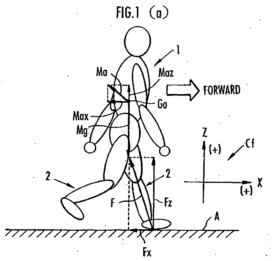
- leg bodies of a bipedal walking moving body for example, as motion states of the leg bodies upon walking, there are a single stance state wherein, as illustrated in Fig. 1(a), only one leg body 2 (a leg body on a front side in an advancing direction in the figure) of both leg bodies 2, 2 of a bipedal walking moving body 1 touches the ground, and a double stance state wherein both leg bodies 2, 2 touch the ground as shown in Fig. 1(b).
- Parenthesis portions T ( , ) on both sides in the equation (1) represent two-component vectors.
- the notation in the form of T ( , ) represents a vector.
- T (Fx, Fz) M ⁇ T (ax, az-g)
- the weight M necessary for deriving the estimated value of the floor reaction force F can be grasped in advance by measurement or the like. Further, with respect to a position of the center of gravity G0 and the acceleration a, it is possible to grasp them in sequence according to a known technique or the like using outputs of sensors such as sensors for detecting bending angles (rotation angles) of the respective joints of the bipedal walking moving body 1, accelerometers, gyro sensors, and so forth, which will be described later in detail.
- floor reaction forces acting from the floor on the respective ground touching portions of both leg bodies two floor reaction forces corresponding to both leg bodies, respectively.
- the floor reaction forces Ff, Fr respectively relating to the leg bodies 2, 2 can be deemed to almost act from specific portions 12f, 12r (e.g. ankle portions) in the vicinity of lower end portions of the respective leg bodies 2, 2 toward the center of gravity G0 of the bipedal walking moving body 1, as shown in Fig. 1(b).
- the weight M necessary for obtaining the estimated values of the floor reaction forces Ff, Fr can be grasped in advance by measurement or the like.
- the acceleration a of the center of gravity G0, the position of the center of gravity G0, and the positions of the specific portions 12f, 12r relative to the center of gravity G0 although details will be described later, it is possible to grasp them in sequence by a known technique or the like using outputs of the sensors detecting bending angles (rotation angles) of the respective joints of the bipedal walking moving body 1, the accelerometers, the gyro sensors, and so forth.
- a method of estimating a floor reaction force for a bipedal walking moving body comprises a first step of judging whether a motion state of the leg bodies of said bipedal walking moving body is a single stance state in which only one of the leg bodies touches the ground, or a double stance state in which both leg bodies touch the ground; a second step of sequentially deriving positions of the center of gravity of said bipedal walking moving body, and sequentially deriving accelerations of said center of gravity in an absolute coordinate system fixed relative to the ground by the use of time series data about the positions of said center of gravity; and a third step of sequentially deriving positions of a specific portion relative to said center of gravity at least in said double stance state, said specific portion predetermined in the neighborhood of a lower end portion of each
- the method of estimating a floor reaction force of the present invention is characterized by further comprising a step of deriving estimated values of said floor reaction force acting on the leg body touching the ground sequentially, in the single stance state of said bipedal walking moving body, based on an equation of motion for said center of gravity expressed by a weight and an acceleration of gravity of the bipedal walking moving body, the acceleration of said center of gravity, and said floor reaction force acting on the leg body touching the ground; and a step of deriving estimated values of said floor reaction forces respectively acting on both leg bodies sequentially, in the double stance state of said bipedal walking moving body, based on an equation of motion for said center of gravity expressed by a weight and an acceleration of gravity of the bipedal walking moving body, the acceleration of said center of gravity, and said floor reaction forces respectively acting on both leg bodies, and an expression of relation between the position of said specific portion of each leg body relative to said center of gravity and said floor reaction force acting on said leg body, said expression of relation being determined based on assumption that said floor reaction force
- the estimated values of the foregoing floor reaction forces are derived by the techniques depending on the respective supporting states.
- the estimated value of the foregoing floor reaction force acting on the leg body touching the ground is derived from values of the weight, the acceleration of gravity, and the acceleration of the center of gravity of the bipedal walking moving body (see the equation (2)) based on the foregoing equation of motion for the center of gravity of the bipedal walking moving body (see the equation (1)).
- the estimated values of the floor reaction forces acting on both leg bodies, respectively are derived from the weight, the acceleration of gravity, and the acceleration of the center of gravity of the bipedal walking moving body, and the position of the specific portion of each leg body relative to the center of gravity (see the equations (5)) based on the foregoing equation of motion for the center of gravity of the bipedal walking moving body (see the equation (3)) and the expression of relation (the equation (4)) between the position of the specific portion of each leg body relative to the foregoing center of gravity, and the foregoing floor reaction force acting on the subject leg body.
- the floor reaction force acting on the free-leg side leg body is "0".
- the weight of the bipedal walking moving body necessary for deriving the estimated value of the floor reaction force may be grasped in advance by measurement or the like.
- sensors that are relatively small in size and easy to be attached to the bipedal walking moving body, such as sensors (potentiometers or the like) detecting bending angles (rotation angles) of the respective joints of the bipedal walking moving body, accelerometers, gyro sensors, and so forth.
- the method of estimating a floor reaction force of the present invention it is possible to grasp the floor reaction forces in real time by the relatively simple technique without attaching force sensors to ankle portions or foot portions of the bipedal walking moving body, or using a force place.
- each leg body is an ankle portion of the leg body.
- the specific portion of each leg body is an ankle portion of the leg body.
- the method of estimating a floor reaction force of the present invention comprises a step of measuring an acceleration, in an upward/downward direction, of a lower portion of a body supported on both leg bodies via a hip joint of each leg body, said lower portion of the body located near said hip joints, wherein, in said first step, the motion state of said bipedal walking moving body is judged such that when the acceleration of said lower portion of the body in the upward/downward direction increases to a predetermined threshold value or more, said double stance state starts while said single stance state finishes and, when the estimated value of said floor reaction force acting on the leg body which precedingly makes a takeoff is lowered to a predetermined threshold value or less in said double stance state, said double stance state finishes while said single stance state starts.
- a floor reaction force estimated value calculation method that differs between the single stance state and the double stance state can be switched at appropriate timing to thereby increase the accuracy of the estimated value of the floor reaction force.
- the acceleration, in the upward/downward direction, of the lower part of the body necessary for judging the motion state of the leg bodies can be easily grasped from an output of an accelerometer by, for example, attaching the accelerometer to the lower part of the body.
- the acceleration, in the upward/downward direction, of the lower part of the body to be measured is an acceleration of the waist in the upward/downward direction.
- various techniques are considered as a technique of grasping the position of the center of gravity of the bipedal walking moving body and the acceleration of the center of gravity in the foregoing second step, and it is possible to use various known methods. However, it is preferable to grasp the position of the center of gravity and the acceleration of the center of gravity according to the following method.
- the method comprises a step of respectively measuring an inclination angle of a body supported on both leg bodies via a hip joint of each leg body, bending angles respectively of at least the hip joint and a knee joint of each leg body, and an acceleration of a predetermined reference point of said bipedal walking moving body in said absolute coordinate system, wherein, in said second step, based on the inclination angle of said body, the bending angles respectively of said hip joints and said knee joints, a rigid body link model formed by expressing said bipedal walking moving body as a linked body of a plurality of rigid bodies, prederived weights of respective rigid-body corresponding portions of the bipedal walking moving body corresponding to the respective rigid bodies of said rigid body link model, and positions of the prederived centers of gravity of the rigid-body corresponding portions in the respective rigid-body corresponding portions, positions of the center of gravity of said bipedal walking moving body relative to said reference point are sequentially derived, accelerations of said center of gravity relative to said reference point are sequentially derived based on time series data about
- the position of the center of gravity of the bipedal walking moving body relative to the reference point is almost determined by a mutual posture relationship among the body, a thigh portion of each leg body from the hip joint to the knee joint, and a crus portion on a lower side below the knee joint.
- the posture relationship can be grasped from those measurement data.
- the position of the center of gravity of the bipedal walking moving body relative to the foregoing reference point can be derived based on the weights of the respective rigid-body corresponding portions of the bipedal walking moving body, the positions of the centers of gravity of the rigid-body corresponding portions in the respective rigid-body corresponding portions (specifically, the positions of the rigid-body corresponding portions in coordinate systems fixed to the respective rigid-body corresponding portions), and the foregoing posture relationship.
- the acceleration of the center of gravity relative to the reference point can be derived as a second-order differentiated value of the position of the center of gravity which is grasped from time series data about the positions of the center of gravity. Therefore, by measuring the acceleration of the reference point in the foregoing absolute coordinate system, the acceleration of the center of gravity of the bipedal walking moving body in the absolute coordinate system can be derived as a composite acceleration of the acceleration of the center of gravity relative to the reference point and the acceleration of the reference point.
- the inclination angles of the body necessary for grasping the acceleration of the bipedal walking moving body as described above can be grasped from outputs of accelerometers and gyro sensors, or inclinometers or the like attached to the body, and the bending angles of the hip joint and the knee joint of each leg body can be grasped from outputs of sensors such as potentiometers attached to the portions of the respective joints.
- the acceleration of the reference point in the absolute coordinate system can be grasped from outputs of sensors such as accelerometers attached to a portion integral with the reference point.
- the weights of the respective rigid-body corresponding portions of the bipedal walking moving body and the positions of the centers of gravity of the rigid-body corresponding portions in the respective rigid-body corresponding portions can be grasped in advance by measurement or the like.
- the reference point is set to the body.
- the sensors such as the accelerometers for measuring the acceleration of the reference point in the absolute coordinate system can be mounted on the body, and therefore, the sensors attached to the leg bodies can be reduced, thereby to make it possible to avoid the situation where those sensors become obstructive to walking motions of the bipedal walking moving body.
- the inclination angle of the body used for deriving the position of the center of gravity comprises inclination angles respectively of the waist and the chest.
- the foregoing rigid body link model is a model expressing a crus portion located on a lower side of the knee joint of each leg body of the bipedal walking moving body, a thigh portion between the knee joint and the hip joint, the waist, and an upper body portion located on an upper side of the waist and including the chest, as rigid bodies, respectively.
- the position of the center of gravity thereof and the acceleration thereof can be grasped accurately to thereby enhance the accuracy of the estimated values of the floor reaction forces.
- the position of the foregoing specific portion of each leg body relative to the center of gravity of the bipedal walking moving body can be derived by deriving the position of the specific portion relative to the reference point in the foregoing third step.
- parameters necessary for deriving the position of the specific portion relative to the reference point differ depending on a set position of the reference point.
- the specific portion is an ankle portion of each leg body, and the reference point is set to the body
- a method of estimating a moment for a bipedal walking moving body is a method of estimating a moment acting on at least one joint of each leg body of the bipedal walking moving body by the use of the estimated values of the floor reaction force on each leg body sequentially derived by the foregoing method of estimating a floor reaction force.
- the method of estimating a moment of the present invention is characterized by comprising a step of respectively measuring an inclination angle of a body supported on both leg bodies via a hip joint of each leg body, bending angles respectively of at least the hip joint and a knee joint of each leg body, and an acceleration of a predetermined reference point of said bipedal walking moving body in said absolute coordinate system; a step of sequentially deriving inclination angles of respective rigid-body corresponding portions of the bipedal walking moving body corresponding to the respective rigid bodies of said rigid body link model, based on the inclination angle of said body, the bending angles respectively of said hip joint and said knee joint of each leg body, and a rigid body link model formed by expressing said bipedal walking moving body as a linked body of a plurality of rigid bodies; a step of sequentially deriving positions of the centers of gravity of the respective rigid-body corresponding portions relative to said reference point, based on the inclination angles of said respective rigid-body corresponding portions, prederived weights of the respective
- the second step in the foregoing floor reaction force estimating method comprises a step of respectively measuring the inclination angle of the body, the bending angles respectively of the hip joint and the knee joint of each leg body, and the acceleration of the reference point of the bipedal walking moving body in the absolute coordinate system, for deriving the position of the center of gravity of the bipedal walking moving body relative to the reference point, and so forth, it is not necessary to newly measure them.
- the rigid body link model may be the same as the rigid body link model used for deriving the position of the center of gravity of the bipedal walking moving body, and so forth.
- the positions of the centers of gravity of the rigid-body corresponding portions in the respective rigid-body corresponding portions (specifically, the positions of the rigid-body corresponding portions in coordinate systems fixed to the respective rigid-body corresponding portions), and the inclination angles of the respective rigid-body corresponding portions, it is possible to derive the positions of the centers of gravity of the respective rigid-body corresponding portions with respect to the reference point.
- the acceleration of the center of gravity of each rigid-body corresponding portion relative to the reference point is derived as a second-order differentiated value of the position of the center of gravity which is grasped from time series data about the positions of the center of gravity.
- the acceleration of the center of gravity of each rigid-body corresponding portion of the bipedal walking moving body in the absolute coordinate system can be derived as a composite acceleration of the acceleration of the center of gravity relative to the reference point and the acceleration of the reference point (the acceleration in the absolute coordinate system).
- an angular velocity of each rigid-body corresponding portion is derived as a second-order differentiated value of the inclination angle which is grasped from time series data about the inclination angles of each rigid-body corresponding portion.
- the position of a floor reaction force acting point of each leg body in the bipedal walking moving body for example, the position of a floor reaction force acting point of each leg body relative to the ankle portion of the leg body, has a close correlation with the inclination angle of the thigh portion of each leg body as the rigid-body corresponding portion of the bipedal walking moving body, and the bending angle of the knee joint of each leg body. Therefore, it is possible to derive an estimated position of the floor reaction force acting point in the bipedal walking moving body based on at least one of the inclination angle of the thigh portion of each leg body and the bending angle of the knee joint thereof.
- the technique based on this inverse dynamics model uses the equation of motion for the translation motion of the center of gravity of each rigid-body corresponding portion of the bipedal walking moving body, and the equation of motion for the rotating motion of the rigid-body corresponding portion (e.g. the rotating motion about the center of gravity of the rigid-body corresponding portion), and derives moments acting on the respective joints of the bipedal walking moving body corresponding to the respective joints of the rigid body link model, in order from the joint closer to the floor reaction force acting point.
- each leg body is a linked body having a thigh portion and a crus portion as rigid-body corresponding portions, respectively
- a force (joint reaction force) acting on a knee joint of the leg body can be grasped by applying an acceleration of the center of gravity of the crus portion, an estimated value of a floor reaction force acting on the leg body, and a value of the weight of the crus portion, into the equation of motion for the translation motion of the center of gravity of the crus portion of each leg body.
- a moment on the knee joint of the leg body can be estimated by applying a joint reaction force acting on the knee joint of the leg body, an angular velocity of the crus portion of the leg body, an estimated position of a floor reaction force acting point of the leg body, an estimated value of a floor reaction force on the leg body, data values relating to a position of the center of gravity of the crus portion in the crus portion and a size (length) of the crus portion, a value of a moment of inertia of the crus portion, and a value of an inclination angle of the crus portion, into the equation of motion for the rotating motion of the crus portion.
- a joint reaction force acting on a hip joint of the leg body can be grasped by applying an acceleration of the center of gravity of the thigh portion, a joint reaction force acting on the knee joint of the leg body, and a value of the weight of the thigh portion, into the equation of motion for the translation motion of the center of gravity of the thigh portion.
- a moment on the hip joint of the leg body can be estimated by applying joint reaction forces respectively acting on the knee joint and the hip joint of the leg body, an angular velocity of the thigh portion of the leg body, data values relating to a position of the center of gravity of the thigh portion in the thigh portion and a size (length) of the thigh portion, a value of a moment of inertia of the thigh portion, and a value of an inclination angle of the thigh portion, into the equation of motion for the rotating motion of the thigh portion.
- Fig. 1 is a diagram for explaining the basic principle of a floor reaction force estimating method of the present invention
- Fig. 2 is a diagram exemplarily showing a human being as a bipedal walking moving body and structures of devices attached to the human being in one embodiment of the present invention
- Fig. 3 is a block diagram for explaining functions of an arithmetic processing unit provided in the devices of Fig. 2
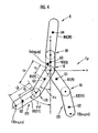
- Fig. 4 is a diagram showing a rigid body link model used in the processing of the arithmetic processing unit of Fig. 3.
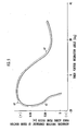
- Fig. 5 is a diagram showing a correlation between advancing direction components of a floor reaction force acting point vector and an inclination angle of a thigh portion during normal walking
- Fig. 5 is a diagram showing a correlation between advancing direction components of a floor reaction force acting point vector and an inclination angle of a thigh portion during normal walking
- Fig. 5 is a diagram showing a correlation between advancing direction components of a floor reaction force acting point vector and an
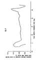
- FIG. 6 is a diagram showing a correlation between vertical direction components of a floor reaction force acting point vector and an inclination angle of a thigh portion during normal walking
- Fig. 7 is a diagram showing a correlation between advancing direction components of a floor reaction force acting point vector and a bending angle of a knee joint upon sitting in a chair
- Fig. 8 is a diagram showing a correlation between advancing direction components of a floor reaction force acting point vector and a bending angle of a knee joint upon standing up from a chair
- Fig. 9 is a diagram showing a correlation between advancing direction components of a floor reaction force acting point vector and an inclination angle of a thigh portion upon going upstairs
- FIG. 10 is a diagram showing a correlation between advancing direction components of a floor reaction force acting point vector and an inclination angle of a thigh portion upon going downstairs.
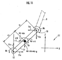
- Fig. 11 is a diagram for explaining the processing in joint moment estimating means of the arithmetic processing unit of Fig. 3
- Fig. 12 is a graph illustrating the states of temporal variations of estimated values of floor reaction forces during normal walking, which are derived by the embodiment of the present invention
- Fig. 13 is a graph illustrating the states of temporal variations of estimated values of floor reaction forces upon going upstairs, which are derived by the embodiment of the present invention
- Fig. 12 is a graph illustrating the states of temporal variations of estimated values of floor reaction forces upon going upstairs, which are derived by the embodiment of the present invention.
- Fig. 14 is a graph illustrating the state of temporal variation of estimated values of floor reaction forces upon standing up from a chair, which are derived by the embodiment of the present invention
- Fig. 15 is a graph illustrating the states of temporal variations of estimated values of moments on a knee joint and a hip joint, which are derived by the embodiment of the present invention.
- the present embodiment is an embodiment wherein a floor reaction force estimating method and a method of estimating a moment of the present invention are applied to a human being as a bipedal walking moving body.
- a human being 1 when its structure is roughly classified, has a pair of left and right leg bodies 2, 2, a body 5 comprising a waist 3 and a chest 4, a head 6, and a pair of left and right arm bodies 7, 7.
- the waist 3 is coupled to the respective leg bodies 2, 2 via a pair of left and right hip joints 8, 8 so that the body 5 is supported on both leg bodies 2, 2.
- the chest 4 of the body 5 is disposed on an upper side of the waist 3 so as to be free inclined toward a forward side of the human being 1 relative to the waist 3.
- the arm bodies 7, 7 extend from both left and right side portions of an upper part of the chest 4, and the head 6 is supported at an upper end portion of the chest 4.
- Each of the leg bodies 2, 2 has a thigh portion 9 extending from the hip joint 8, and a crus portion 11 extending from a tip of the thigh portion 9 via a knee joint 10, and a foot portion 13 is coupled to a tip portion of the crus portion 11 via an ankle portion (ankle joint) 12.
- the human being 1 for estimating a floor reaction force acting on each leg body 2 of the human being 1 having the foregoing structure, and further estimating moments acting on the knee joint 10 and the hip joint 8, the human being 1 is equipped with the following devices.
- the chest 4 of the body 5 is mounted with a gyro sensor 14 (hereinafter referred to as the chest gyro sensor 14) that produces an output corresponding to an angular velocity following an inclination of the chest 4, an accelerometer 15 (hereinafter referred to as the chest forward/backward accelerometer 15) that produces an output corresponding to an acceleration of the chest 4 in a forward/backward direction, an arithmetic processing unit 16 comprising a CPU, a RAM, a ROM, and so forth, and a battery 17 serving as a power supply for the arithmetic processing unit 16 and so forth.
- a gyro sensor 14 that produces an output corresponding to an angular velocity following an inclination of the chest 4
- an accelerometer 15 hereinafter referred to as the chest forward/backward accelerometer 15
- the chest forward/backward accelerometer 15 that produces an output corresponding to an acceleration of the chest 4 in a forward/backward direction
- an arithmetic processing unit 16 comprising
- these chest gyro sensor 14, chest forward/backward accelerometer 15, arithmetic processing unit 16, and battery 17 are, for example, received in a reception member 18 in the form of a shoulder bag that is fixed to the chest 4 using a belt or the like not shown, and unitarily fixed to the chest 4 via the reception member 18.
- the acceleration represented by the output of the chest accelerometer 15 is, more specifically, an acceleration in a forward/backward direction in a direction of horizontal section of the chest 4 (a direction perpendicular to a central axis of the chest 4).
- a forward/backward direction in a direction of horizontal section of the chest 4
- X-axis direction of the absolute coordinate system in Fig. 2 a direction perpendicular to a central axis of the chest 4
- Z-axis direction of the absolute coordinate system in Fig. 2 it is an acceleration in a direction inclined relative to the horizontal direction by an inclination angle of the chest 4 relative to the vertical direction.
- a gyro sensor 19 (hereinafter referred to as the waist gyro sensor 19) for producing an output corresponding to an angular velocity following an inclination of the waist 3, an accelerometer 20 (hereinafter referred to as the waist forward/backward accelerometer 20) for producing an output corresponding to an acceleration of the waist 3 in a forward/backward direction, and an accelerometer 21 (hereinafter referred to as the waist upward/downward accelerometer 21) for producing an output corresponding to an acceleration of the waist 3 in an upward/downward direction are unitarily mounted/fixed to the waist 3 of the body 5 via fixing means such as a belt not shown.
- the waist forward/backward accelerometer 20 is, more specifically, a sensor, like the chest forward/backward accelerometer 15, for detecting an acceleration in a forward/backward direction in a direction of horizontal section of the waist 3 (a direction perpendicular to a central axis of the waist 3).
- the waist upward/downward accelerometer 21 is, more specifically, a sensor for detecting an acceleration in an upward/downward direction in a direction of the central axis of the waist 3 (this is perpendicular to the acceleration detected by the waist forward/backward accelerometer 20).
- the waist forward/backward accelerometer 20 and the waist upward/downward accelerometer 21 may be unitarily formed as a two-axis accelerometer.
- hip joint 8 and the knee joint 10 of each leg body 2 are mounted with a hip joint angle sensor 22 and a knee joint angle sensor 23 that produce outputs corresponding to respective bending angles ⁇ c and ⁇ d.
- hip joint angle sensors 22 although only the hip joint angle sensor 22 relating to the hip joint 8 of the leg body 2 on this side (the right side of the human being 1 facing forward) is shown in Fig. 2, the hip joint 8 of the leg body 2 on the other side (the left side of the human being 1 facing forward) is mounted with the hip joint angle sensor 22 concentrically with the hip joint angle sensor 22 on this side.
- each hip joint angle sensor 22 is, more specifically, a rotation angle of the thigh portion 9 of the leg body 2 about the hip joint 8 (about a central axis of the hip joint 8 in a leftward/rightward direction of the human being 1) relative to the waist 3, using as a criterion the state where a posture relationship between the waist 3 and the thigh portion 9 of the leg body 2 is in a predetermined posture relationship (e.g.
- each knee joint angle sensor 23 is a rotation angle of the crus portion 11 about the knee joint 10 (about a central axis of the knee joint 10 in a leftward/rightward direction of the human being 1) relative to the thigh portion 9, using as a criterion the state where a posture relationship between the thigh portion 9 and the crus portion 11 of the leg body 2 is in a predetermined posture relationship (e.g. a posture relationship in which the central axis of the thigh portion 9 and a central axis of the crus portion 11 become substantially parallel to each other).
- a posture relationship between the thigh portion 9 and the crus portion 11 of the leg body 2 is in a predetermined posture relationship (e.g. a posture relationship in which the central axis of the thigh portion 9 and a central axis of the crus portion 11 become substantially parallel to each other).
- the foregoing respective sensors 14, 15, and 19 to 23 are connected to the arithmetic processing unit 16 via signal lines not shown, for inputting outputs thereof into the arithmetic processing unit 16.
- the foregoing arithmetic processing unit 16 is provided with functional means as shown in Fig. 3. Specifically, the arithmetic processing unit 16 is provided with leg body motion judging means 24 for judging whether the motion state of the leg bodies 2, 2 of the human being 1 is the single stance state (state of Fig. 1(a)) or the double stance state (state of Fig. 1(b)), using detection data of the waist upward/downward accelerometer 21 and data about an estimated value of a floor reaction force of each leg body 2 derived by later-described floor reaction force estimating means 36.
- leg body motion judging means 24 for judging whether the motion state of the leg bodies 2, 2 of the human being 1 is the single stance state (state of Fig. 1(a)) or the double stance state (state of Fig. 1(b)), using detection data of the waist upward/downward accelerometer 21 and data about an estimated value of a floor reaction force of each leg body 2 derived by later-described floor reaction force estimating means 36.
- the arithmetic processing unit 16 is provided with chest inclination angle measuring means 25 for measuring an inclination angle ⁇ a of the chest 4 in the absolute coordinate system Cf (specifically, an inclination angle ⁇ a relative to, for example, the vertical direction; see Fig. 2), using detection data of the chest forward/backward accelerometer 15 and the chest gyro sensor 14, and waist inclination angle measuring means 26 for measuring an inclination angle ⁇ b of the waist 3 in the absolute coordinate system Cf (specifically, an inclination angle ⁇ b relative to, for example, the vertical direction; see Fig. 2), using detection data of the waist forward/backward accelerometer 20 and the waist gyro sensor 19.
- the body coordinate system Cp is, more specifically, a coordinate system (coordinate system of which directions of three axes are the same as those of the foregoing absolute coordinate system Cf) wherein the origin O is set to, for example, a middle point of a line connecting the respective centers of the left and right hip joints 8, 8 of the human being 1, a z-axis direction is set to the vertical direction, and an x-axis direction is set to the horizontal direction headed forward of the human being 1.
- leg body posture calculating means 28 for deriving inclination angles ⁇ c and ⁇ d respectively of the thigh portion 9 and the crus portion 11 of each leg body 2 in the absolute coordinate system Cf (specifically, inclination angles ⁇ c and ⁇ d relative to, for example, the vertical direction; see Fig. 2), using detection data of the hip joint angle sensor 22 and the knee joint angle sensor 23 of the leg body 2 and data about the inclination angle ⁇ b of the waist 3 by the foregoing waist inclination angle measuring means 26.
- the arithmetic processing unit 16 is provided with respective-portion center of gravity position calculating means 29 for deriving positions of the centers of gravity of respective rigid-body corresponding portions (specifically, positions of the centers of gravity of respective rigid-body corresponding portions in the foregoing body coordinate system Cp) of the human being 1 corresponding to a later-described rigid body link model, using data about the inclination angle ⁇ a of the chest 4, the inclination angle ⁇ b of the waist 3, and the inclination angle ⁇ c of the thigh portion 9 and the inclination angle ⁇ d of the crus portion 11 of each leg body 2 obtained by the foregoing chest inclination angle measuring means 25, waist inclination angle measuring means 26, and leg body posture calculating means 28, body center of gravity position calculating means 30 for deriving a position of the center of gravity of the whole human being 1 in the foregoing body coordinate system Cp, using data about the positions of the centers of gravity of the respective rigid-body corresponding portions, ankle position calculating means 31 for deriving, using data
- leg body respective-portion acceleration calculating means 33 for deriving accelerations (translation accelerations) of the centers of gravity of the thigh portion 9 and the crus portion 11, respectively, of each leg body 2 in the absolute coordinate system Cf, using data about the positions of the centers of gravity of the respective rigid-body corresponding portions of the human being 1 (specifically, the positions of the centers of gravity of the rigid-body corresponding portions relating to each leg body 2) by the foregoing respective-portion center of gravity position calculating means 29 and data about the acceleration a 0 of the origin O of the body coordinate system Cp by the foregoing reference acceleration measuring means 27, leg body respective-portion angular velocity calculating means 34 for deriving angular velocities of the thigh portion 9 and the crus portion 11 of each leg body 2 in the absolute coordinate system Cf, using data about the respective inclination angles ⁇ c and ⁇ d of the thigh portion 9 and the crus portion 11 of the leg body 2 by the foregoing leg
- the arithmetic processing unit 16 is provided with floor reaction force estimating means 36 for deriving an estimated value of a floor reaction force acting on each leg body 2, using data about the acceleration a of the body center of gravity by the foregoing body center of gravity acceleration calculating means 32, data about the position of the ankle portion 12 of each leg body 2 relative to the body center of gravity by the foregoing ankle position calculating means 31, and data about the judgement result on the motion state of the leg bodies 2, 2 by the foregoing leg body motion judging means 24, and joint moment estimating means 37 for estimating moments acting on the knee joint 10 and the hip joint 8, respectively, of each leg body 2, using data about this estimated value of the floor reaction force, data about the accelerations of the centers of gravity of the thigh portion 9 and the crus portion 11 of each leg body 2 by the foregoing leg body respective-portion acceleration calculating means 33, data about the angular velocities of the thigh portion 9 and the crus portion 11 of each leg body 2 by the leg body respective-portion angular velocity calculating means
- the processing by the arithmetic processing unit 16 is executed in sequence per predetermined cycle time as will be described hereinbelow, to thereby successively derive estimated values of floor reaction forces and so forth acting on each leg body 2.
- the arithmetic processing unit 16 executes the processing of the foregoing leg body motion judging means 24.
- detection data about the acceleration of the waist 3 in the upward direction by the foregoing waist upward/downward accelerometer 21 is compared with a prescribed threshold value determined in advance per the foregoing cycle time. Then, when a detected value of the acceleration exceeds the threshold value, it is judged that the double stance state as shown in the foregoing figure 1(b) starts, while the single stance state as shown in the foregoing figure 1(a) finishes.
- the foregoing leg body motion judging means 24 judges the start of the double stance state and the finish of the single stance state.
- the initial state of the motion state of the leg bodies 2, 2 is the double stance state
- the leg body motion judging means 24 judges that the motion state of the leg bodies 2, 2 is the double stance state until an estimated value of a floor reaction force acting on either one of the leg bodies 2, 2 is lowered to the foregoing threshold value or less.
- the arithmetic processing unit 16 executes the processing by the foregoing chest inclination angle measuring means 25 and waist inclination angle measuring means 26.
- an inclination angle ⁇ a of the chest 4 in the absolute coordinate system Cf is derived in sequence per the foregoing cycle time according to a known technique using the processing of a so-called Kalman filter, based on detection data about the acceleration of the chest 4 in the forward/backward direction and the angular velocity of the chest 4 which are inputted from the chest forward/backward accelerometer 15 and the chest gyro sensor 14, respectively.
- an inclination angle ⁇ b of the waist 3 in the absolute coordinate system Cf is derived in sequence using the processing of the Kalman filter, based on detection data about the acceleration of the waist 3 in the forward/backward direction and the angular velocity of the waist 3 which are inputted from the waist forward/backward accelerometer 20 and the waist gyro sensor 19, respectively.
- the inclination angles ⁇ a and ⁇ b respectively of the chest 4 and the waist 3 in the absolute coordinate system Cf are inclination angles relative to, for example, the vertical direction (direction of gravity).
- inclination angles of the chest 4 and the waist 3 can be accurately measured using the processing of the Kalman filter.
- the arithmetic processing unit 16 executes the processing of the foregoing leg body posture calculating means 28 and the processing of the foregoing reference acceleration measuring means 27.
- inclination angles ⁇ c and ⁇ d (inclination angles relative to the vertical direction; see Fig. 2) of the thigh portion 9 and the crus portion 11 of each leg body 2 in the absolute coordinate system Cf are derived per the foregoing cycle time in the following manner.
- the inclination angle ⁇ c of the thigh portion 9 of each leg body 2 is calculated from a current-time value of detection data about the bending angle ⁇ c of the hip joint 8 by the foregoing hip joint angle sensor 22 attached to the leg body 2 and a current-time value of the inclination angle ⁇ b of the waist 3 derived by the foregoing waist inclination angle measuring means 25, using the following equation (6).
- ⁇ c ⁇ b + ⁇ c
- the inclination angle ⁇ b of the waist 3 takes a negative value when the waist 3 is inclined relative to the vertical direction such that an upper end portion of the waist 3 is projected forward of the human being 1 as compared with a lower end portion thereof
- the bending angle ⁇ c of the hip joint 8 takes a positive value when the thigh portion 9 is inclined relative to the central axis of the waist 3 such that a lower end portion of the thigh portion 9 is projected forward of the human being 1.
- the inclination angle ⁇ d of the crus portion 11 of each leg body 2 is calculated from a current-time value of the inclination angle ⁇ c of the thigh portion 9 derived in the foregoing manner and a current-time value of detection data about the bending angle ⁇ d of the knee joint 10 by the foregoing knee joint angle sensor 23 attached to the leg body 2, using the following equation (7).
- ⁇ d ⁇ c - ⁇ d
- the bending angle of the knee joint 10 takes a positive value when the crus portion 11 is inclined relative to the central axis of the thigh portion 9 toward the back side of the thigh portion 9.
- the arithmetic processing unit 16 executes the processing of the foregoing respective-portion center of gravity position calculating means 29, and derives positions (positions relative to the origin of the body coordinate system Cp) of the centers of gravity of respective rigid-body corresponding portions of the human being 1 in the foregoing body coordinate system Cp, using a rigid body link model described hereinbelow.
- a rigid body link model R used in the present embodiment is a model that expresses the human being 1 by linking together rigid bodies R1, R1 corresponding to the thigh portions 9 of the respective leg bodies 2, 2, rigid bodies R2, R2 corresponding to the crus portions 11, 11, a rigid body R3 corresponding to the waist 3, and a rigid body R4 corresponding to a portion 38 (hereinafter referred to as the upper body portion 38) in a combination of the foregoing chest 4, arm bodies 7, 7, and head 6.
- a linkage portion between each rigid body R1 and the rigid body R3, and a linkage portion between each rigid body R1 and the rigid body R2 correspond to the hip joint 8 and the knee joint 10, respectively.
- a linkage portion between the rigid body R3 and the rigid body R4 is a tilting fulcrum portion 39 for the chest 4 relative to the waist 3.
- positions of the centers of gravity G1, G2, G3, and G4 of the rigid-body corresponding portions (the thigh portion 9 and the crus portion 11 of each leg body 2, the waist 3, and the upper body portion 38) of the human being 1 corresponding to the respective rigid bodies R1 to R4 of such a rigid body link model R, in the respective rigid-body corresponding portions, are derived in advance and stored in a memory, not shown, of the arithmetic processing unit 16.
- the positions of the centers of gravity G1, G2, G3, and G4 of the respective rigid-body corresponding portions stored/retained in the arithmetic processing unit 16 are positions each in a coordinate system that is fixed relative to each rigid-body corresponding portion.
- data representing each of the positions of the centers of gravity G1, G2, G3, and G4 of the respective rigid-body corresponding portions for example, a distance in a direction of the central axis of the rigid-body corresponding portion from the central point of a joint at one end portion of such a rigid-body corresponding portion is used. Specifically, for example, as shown in Fig.
- the position of the center of gravity G1 of each thigh portion 9 is given as a position with a distance t1 in the direction of the central axis of the thigh portion 9 from the center of the hip joint 8 of the thigh portion 9
- the position of the center of gravity G2 of each crus portion 11 is given as a position with a distance t2 in the direction of the central axis of the crus portion 11 from the center of the knee joint 10 of the crus portion 11, and values of those distances t1 and t2 are derived in advance and stored/retained in the arithmetic processing unit 16.
- This also applies to the positions of the centers of gravity G3, G4 of the other rigid-body corresponding portions.
- the position of the center of gravity G4 of the upper body portion 38 is affected by movement of the arm bodies 7, 7 included in the upper body portion 38.
- the position of the center of gravity G4 of the upper body portion 38 does not change much, and is, for example, substantially equivalent to a position of the center of gravity G4 of the upper body portion 38 in the erect posture state.
- data about weights of the respective rigid-body corresponding portions are derived in advance and stored/retained in the arithmetic processing unit 16.
- the weight of the crus portion 11 is a weight including the foot portion 13.
- the data stored/retained beforehand in the arithmetic processing unit 16 as described above may be obtained by actual measurement or the like, or may be estimated from a height and weight of the human being 1 based on human average statistical data.
- the positions of the centers of gravity G1, G2, G3, and G4, the weights, and the sizes of the foregoing respective rigid-body corresponding portions have correlation with a height or weight of a human being and, based on the correlation, it is possible to estimate relatively accurately the positions of the centers of gravity G1, G2, G3, and G4, the weights, and the sizes of the foregoing respective rigid-body corresponding portions from data about the height and weight of the human being.
- the positions and postures of the respective rigid-body corresponding portions in the body coordinate system Cp can be derived from data about the inclination angles ⁇ a to ⁇ d and data about the sizes of the respective rigid-body corresponding portions. Therefore, the positions of the centers of gravity G1, G2, G3, and G4 of the respective rigid-body corresponding portions in the body coordinate system Cp are derived.
- the arithmetic processing unit 16 executes the processing of the foregoing body center of gravity position calculating means 30, and derives a position (xg, zg) of the body center of gravity G0 of the human being 1 in the body coordinate system Cp using data about the positions of the centers of gravity G1, G2, G3, and G4 of the respective rigid-body corresponding portions and data about the weights of the respective rigid-body corresponding portions.
- the position of the center of gravity G3 of the waist 3 in the body coordinate system Cp and the weight thereof are (x3, z3) and m3, respectively
- the position of the center of gravity G4 of the upper body portion 38 and the weight thereof are (x4, z4) and m4, respectively
- the position of the center of gravity G1 of the thigh portion 9 of the leg body 2 on the left side of the human being 1 facing forward and the weight thereof are (x1L, z1L) and m1L, respectively
- the position of the center of gravity G2 of the crus portion 11 of the same leg body 2 and the weight thereof are (x2L, z2L) and m2L
- the position of the center of gravity G1 of the thigh portion 9 of the leg body 2 on the right side and the weight thereof are (x1R, z1R) and m1R, respectively
- the position of the center of gravity G2 of the crus portion 11 of the same leg body 2 and the weight thereof are (x2R, z2R
- the arithmetic processing unit 16 After executing the processing of the body center of gravity position calculating means 30 as described above, the arithmetic processing unit 16 further executes the processing of the foregoing body center of gravity acceleration calculating means 32 and the processing of the foregoing ankle position calculating means 31.
- a second-order differentiated value of the position (xg, zg) of the body center of gravity G0 in the body coordinate system Cp that is, an acceleration T (d 2 xg/dt 2 , d 2 zg/dt 2 ) of the body center of gravity G0 relative to the origin O of the body coordinate system Cp, is derived.
- a current-time value of data about the inclination angle ⁇ b of the waist 3 derived by the foregoing waist inclination angle measuring means 26, and data about the sizes (lengths) of the thigh portion 9 and the crus portion 11, a position of the ankle portion 12 of each leg body 2 in the foregoing body coordinate system Cp is derived by the processing like the processing of the foregoing respective-portion center of gravity position calculating means 29. Specifically, referring to Fig.
- a floor reaction force acting on the ground non-touching side leg body 2 is T (0, 0).
- the arithmetic processing unit 16 executes the processing of the foregoing leg body respective-portion acceleration calculating means 33, leg body respective-portion angular velocity calculating means 34, and floor reaction force acting point estimating means 35.
- accelerations (more specifically, coordinate components of the accelerations in the absolute coordinate system Cf) respectively of the thigh portion 9 and the crus portion 11 in the absolute coordinate system Cf are derived.
- a vector position vector of a floor reaction force acting point relative to the ankle portion 12; hereinafter referred to as the floor reaction force acting point vector
- the floor reaction force acting point vector is derived as data representing a position of the floor reaction force acting point, from, for example, a current-time value of the inclination angle ⁇ c of the thigh portion 9 derived by the foregoing leg body posture calculating means 28, based on predetermined correlations as shown in Figs. 5 and 6.
- the inclination angle ⁇ c of the thigh portion 9 or the bending angle ⁇ d of the knee joint 10 of the leg body 2 touching the ground has relatively significant correlation with the floor reaction force acting point.
- the foregoing floor reaction force acting point vector specifically, components of the floor reaction force acting point vector in the advancing direction (X-axis direction) of the human being 1, and components of the floor reaction force acting point vector in the vertical direction (Z-axis vector), respectively change with respect to, for example, the inclination angle ⁇ c of the thigh portion 9 as shown in FIGS. 5 and 6.
- the negative inclination angle ⁇ c of the thigh portion 9 is an angle when the thigh portion 9 is inclined relative to the central axis of the waist 3 so that the leg body 2 extends to the back side of the human being 1 (e.g. the leg body 2 on the right side of the human being 1 facing forward in Fig. 2)
- the positive inclination angle ⁇ c is an angle when the thigh portion 9 is inclined relative to the central axis of the waist 3 so that the leg body 2 exists on the front side of the human being 1 (e.g. the leg body 2 on the left side of the human being 1 facing forward in Fig. 2).
- a value of the floor reaction force acting point vector differs between a decreasing stage of the inclination angle ⁇ c and an increasing stage thereof. Therefore, in the present embodiment, upon preparing the foregoing approximate expression, a transition of the foregoing correlation from a landing of the heel of the foot portion 13 on the floor to a takeoff of the tiptoe from the floor is classified into a first phase (a phase of a1 in Fig. 5; a phase of b1 in Fig.
- px x 1 ⁇ ⁇ c 6 + x 2 ⁇ ⁇ c 5 + x 3 ⁇ ⁇ c 4 + x 4 ⁇ ⁇ c 3 + x 5 ⁇ ⁇ c 2 + x 6 ⁇ ⁇ c + x 7 (x 1 to x 7 are constant values).
- the floor reaction force acting point vector upon deriving the floor reaction force acting point vector, it is judged whether the inclination angle ⁇ c of the thigh portion 9 is positive or negative, and further judged whether the inclination angular velocity of the thigh portion 9 calculated by first-order differentiation of time series data about the inclination angles ⁇ c of the thigh portion 9 is positive or negative. Further, from judged positive or negative of the inclination angle ⁇ c and judged positive or negative of the inclination angular velocity, it is judged which of the phases is manifested currently and, by putting a current-time value of the inclination angle ⁇ c of the thigh portion 9 into the approximate expression of the judged phase, the floor reaction force acting point vector is calculated. Thereby, the value of the floor reaction force acting point vector in the decreasing stage of the inclination angle ⁇ c of the thigh portion 9, and the value of the floor reaction force acting point vector in the increasing stage thereof can be discriminatingly calculated.
- the correlation between the inclination angle ⁇ c of the thigh portion 9 of the leg body and the floor reaction force acting point vector is approximated by the polynomials to thereby derive the floor reaction force acting point vector.
- the position of the floor reaction force acting point also has correlation with the bending angle of the knee joint 10 of the leg body 2 touching the ground. Therefore, the position of the floor reaction force acting point may be estimated from the bending angle ⁇ d of the knee joint 10 measured by the knee joint angle sensor 23, instead of the inclination angle ⁇ c of the thigh portion 9. Alternatively, using both the inclination angle ⁇ c of the thigh portion 9 and the bending angle ⁇ d of the knee joint 10, the position of the floor reaction force acting point may be estimated by the use of a map or the like.
- a correlation shown in Fig. 7 (upon sitting in the chair) or Fig. 8 (upon standing up from the chair) is established between the position of the floor reaction force acting point and the bending angle ⁇ d of the knee joint 10 and, when going upstairs or downstairs, Fig. 9 (upon going upstairs) or Fig. 10 (upon going downstairs) is established between the position of the floor reaction force acting point and the inclination angle ⁇ c of the thigh portion 9. Therefore, upon sitting in the chair or standing up, the position of the floor reaction force acting point can be estimated from the bending angle ⁇ d of the knee joint 10 based on the correlation of Fig. 7 or Fig. 8, while, upon going upstairs or downstairs, the position of the floor reaction force acting point can be estimated from the inclination angle ⁇ c of the thigh portion 9 based on the correlation of Fig. 9 or Fig. 10.
- the arithmetic processing unit 16 executes the processing of the foregoing joint moment estimating means 37, and derives moments acting on the knee joint 10 and the hip joint 8 of each leg body 2. This processing is carried out based on a so-called inverse dynamics model using current-time values of the data respectively derived by the foregoing floor reaction force estimating means 36, leg body respective-portion acceleration calculating means 33, leg body respective-portion angular velocity calculating means 34, floor reaction force acting point estimating means 35, and leg body posture calculating means 28.
- This inverse dynamics model uses an equation of motion for translation motion of each rigid-body corresponding portion of the human being 1 and an equation of motion for rotating motion thereof so as to derive moments acting on joints in order from the joint closer to the floor reaction force acting point.
- the moments acting on the knee joint 10 and the hip joint 8 of each leg body 2 are derived in order.
- a force (joint reaction force) acting on the ankle portion 12 at a tip portion of the crus portion 11 a force (joint reaction force) acting on the portion of the knee joint 10 of the crus portion 11, and a translation acceleration of the center of gravity G2 of the crus portion 11 are respectively given as T (F 1 x, F 1 z), T (F 2 x, F 2 z), and T (a 2 x, a 2 z) according to the component notation in the absolute coordinate system Cf, and the weight of the crus portion 11 is given as m 2 .
- the acceleration T (a 2 x, a 2 z) of the center of gravity G2 of the crus portion 11 is derived by the foregoing leg body respective-portion acceleration calculating means 33.
- the joint reaction force T (F 1 x, F 1 z) acting on the ankle portion 12 at the tip portion of the crus portion 11 is approximately equal to the estimated value of the floor reaction force derived by the foregoing floor reaction force estimating means 36 for the leg body 2 having the crus portion 11.
- the joint reaction force T (F 1 x, F 1 z) is the floor reaction force T (Frx, Frz) of the foregoing equations (5) and, when the leg body 2 is the front-side leg body, it is the floor reaction force T (Ffx, Ffz) of the foregoing equations (5).
- a moment acting on the ankle portion 12 at the tip portion of the crus portion 11 is M 1
- a moment acting on the portion of the knee joint 10 of the crus portion 11 is M 2
- a moment of inertia about the center of gravity G2 of the crus portion 11 is I G2
- an angular velocity about the center of gravity G2 of the crus portion 11 is ⁇ 2 .
- M 1 in the equation (11) is a moment obtained as the outer product (vector product) of a floor reaction force acting point vector derived by the foregoing floor reaction force acting point estimating means 35 with respect to the leg body 2 having the crus portion 11 relating to the equation (11), and a floor reaction force vector derived by the foregoing floor reaction force estimating means 36 with respect to that leg body 2.
- ⁇ 2 is an angular velocity of the crus portion 11 derived by the foregoing leg body respective-portion angular velocity calculating means 34.
- ⁇ d is an inclination angle of the crus portion 11 derived by the foregoing leg body posture calculating means 28.
- T (F 1 x, F 1 z) is, as described before, the estimated value of the floor reaction force derived by the floor reaction force estimating means 36. Further, T (F 2 x, F 2 z) is derived by the foregoing equation (10). The moment of inertia I G2 is derived in advance and stored in the arithmetic processing unit 16 along with data about the weight m 2 and size of the crus portion 11, and so forth.
- the moment M 2 acting on the knee joint 10 is derived from data about the estimated value of the floor reaction force by the floor reaction force estimating means 36, data about the floor reaction force acting point vector by the floor reaction force acting point estimating means 35, data about the angular velocity ⁇ 2 of the crus portion 11 by the leg body respective-portion angular velocity calculating means 34, data about the inclination angle ⁇ d of the crus portion 11 by the leg body posture calculating means 28, data about the joint reaction force T (F 2 x, F 2 z) derived by the foregoing equation (10), and data about the moment of inertia I G2 , the size (Ld), and the position (t 2 ) of the center of gravity G2 of the crus portion 11 derived in advance, using the foregoing equation (11).
- the joint moment estimating means 37 derives, according to the processing like the processing of calculation thereof, a moment acting on the portion of the hip joint 8 of the thigh portion 9.
- the basic idea of this processing is the same as the technique of deriving the moment M 2 of the knee joint 10, and therefore, detailed showing and explanation are omitted. An outline thereof is as follows.
- a joint reaction force T (F 3 x, F 3 z) acting on the portion of the hip joint 8 of the thigh portion 9 is derived using the following equation (12) (an equation in the same form as the foregoing equation (10)) based on an equation of motion for the translation motion of the center of gravity G1 (see Fig. 4) of the thigh portion 9.
- T (F 3 x, F 3 z) T (F 2 x - m 1 ⁇ a 1 x, F 2 z - m 1 ⁇ a 1 z - m 1 ⁇ g)
- T (F 2 x, F 2 z) is the joint reaction force of the knee joint 10 derived before by the foregoing equation (10).
- T (a 1 x, a 1 z) is an acceleration (translation acceleration) of the center of gravity G1 of the thigh portion 9 in the absolute coordinate system Cf, which is derived by the foregoing leg body respective-portion acceleration calculating means 33.
- m 1 is the weight of the thigh portion 9 derived in advance
- g is the acceleration of gravity.
- a moment M 3 acting on the portion of the hip joint 8 of the thigh portion 9 is derived using the following equation (13) (an equation in the same form as the foregoing equation (11)) based on an equation of motion for the rotating motion about the center of gravity G1 of the thigh portion 9.
- M 3 M 2 - I G1 ⁇ ⁇ 1 + F 2 x ⁇ t 1 ' ⁇ cos ⁇ c - F 2 z ⁇ t 1 ' ⁇ sin ⁇ c + F 3 x ⁇ t 1 ⁇ cos ⁇ c - F 3 z ⁇ t 1 ⁇ sin ⁇ c
- M 2 is the moment on the knee joint 10 derived by the foregoing equation (11)
- T (F 2 x, F 2 z) is the joint reaction force on the knee joint 10 derived by the foregoing equation (10)
- T (F 3 x, F 3 z) is the joint reaction force on the hip joint 8 derived by the foregoing equation (12)
- I G1 is a moment of inertia about the center of gravity G1 of the thigh portion 9 derived in advance
- ⁇ 1 is an angular velocity of the thigh portion 9 derived by the foregoing leg body respective-portion angular velocity calculating means 34
- ⁇ c is an inclination angle of the thigh portion 9 derived by the foregoing leg body posture calculating means 28.
- t 1 is a distance from the center of the hip joint 8 to the center of gravity G1 of the thigh portion 9 (see Fig. 4), and t 1 ' is a distance from the center of the knee joint 10 to the center of gravity G1 of the thigh portion 9 (Lc-t 1 in Fig. 4), which are determined based on the position of the center of gravity G1 and the size (length) of the thigh portion 9 derived in advance.
- the processing described above is successively executed per cycle time of the foregoing arithmetic processing unit 16, so that the floor reaction force acting on each leg body 2, and the moments acting on the knee joint 10 and the hip joint 8 of each leg body 2 are sequentially estimated in real time.
- the derived estimated values of the moments on the knee joints 10 and the hip joints 8 are used for a control of, for example, a device assisting walking of the human being 1 (a device including electric motors or the like that can give auxiliary torques to the knee joints 10 and the hip joints 8).
- Figs. 12 to 14 The states of temporal variations of estimated values of floor reaction forces (specifically, absolute values of the estimated values of the floor reaction forces) derived by the foregoing processing of the arithmetic processing unit 16 are illustrated in Figs. 12 to 14 by solid lines. Further, the states of temporal variations of estimated values of moments on the knee joint 10 and the hip joint 8 derived by the processing of the arithmetic processing unit 16 are illustrated in Fig. 15 by solid lines.
- Figs. 12 and 15 are illustration wherein the human being 1 walks on a flatland at a substantially constant speed
- Fig. 13 is illustration wherein the human being 1 walks upstairs
- Fig. 14 is illustration wherein the human being 1 stands up from the state of sitting in a chair.
- Figs. 12 and 15 are illustration wherein the human being 1 walks on a flatland at a substantially constant speed
- Fig. 13 is illustration wherein the human being 1 walks upstairs
- Fig. 14 is illustration wherein the human being 1 stands up from the state
- comparative examples (corresponding to true values of floor reaction forces) obtained by actually measuring floor reaction forces using a force meter or the like are also shown by imaginary lines. Further, in Fig. 15, comparative examples (corresponding to true values of moments on the knee joint 10 and the hip joint 8) obtained by actually measuring moments on the knee joint 10 and the hip joint 8 using a torque meter or the like are also shown by imaginary lines.
- the accurate estimated values of the floor reaction forces are obtained irrespective of the motion type or motion environment of the leg bodies 2. Further, in the present embodiment, as shown in Fig. 15, the moments on the knee joint 10 and the hip joint 8 can also be estimated with relatively high accuracy using the estimated values of the floor reaction forces.
- the present invention is also applicable to a bipedal walking robot as a bipedal walking moving body.
- the bipedal walking robot may have a structure where a waist and a chest are integral with each other.
- the gyro sensor and the forward/backward accelerometer to either one of the waist and the chest, and estimate floor reaction forces and moments on joints of leg bodies in the same manner as in the present embodiment.
- the bipedal walking robot it is also possible grasp bending angles of hip joints and knee joints based on control amounts of a controller for actuators of those joints.
- the detection data of the waist upward/downward accelerometer 21 is uses as it is for judging the motion state of the leg bodies 2.
- detection data it is possible to use, for example, values of components of the acceleration a 0 of the waist 3 in the vertical direction (Z-axis direction) in the absolute coordinate system Cf, which are derived by the foregoing reference acceleration measuring means 27.
- the present invention is useful in that, when performing walking assistance or walking control of a bipedal walking moving body such as a human being or a robot, floor reaction forces and joint moments acting on leg bodies of the moving body can be grasped.
Landscapes
- Health & Medical Sciences (AREA)
- Engineering & Computer Science (AREA)
- Life Sciences & Earth Sciences (AREA)
- Public Health (AREA)
- Veterinary Medicine (AREA)
- Animal Behavior & Ethology (AREA)
- General Health & Medical Sciences (AREA)
- Mechanical Engineering (AREA)
- Biophysics (AREA)
- Physics & Mathematics (AREA)
- Surgery (AREA)
- Molecular Biology (AREA)
- Medical Informatics (AREA)
- Heart & Thoracic Surgery (AREA)
- Biomedical Technology (AREA)
- Dentistry (AREA)
- Oral & Maxillofacial Surgery (AREA)
- Pathology (AREA)
- Robotics (AREA)
- Combustion & Propulsion (AREA)
- Rheumatology (AREA)
- Epidemiology (AREA)
- Orthopedic Medicine & Surgery (AREA)
- Transportation (AREA)
- Rehabilitation Therapy (AREA)
- Chemical & Material Sciences (AREA)
- Pain & Pain Management (AREA)
- Physical Education & Sports Medicine (AREA)
- Manipulator (AREA)
Abstract
Description
Further, an approximate expression of the third phase a3 in the correlation of Fig. 5 is expressed by, for example, a fourth-order polynomial function in the form of
Further, an approximate expression of the third phase b3 in the correlation of Fig. 6 is expressed by, for example, a third-order polynomial function in the form of
Claims (9)
- A method of estimating a floor reaction force acting on each of leg bodies of the bipedal walking moving body, comprising:a first step of judging whether a motion state of the leg bodies of said bipedal walking moving body is a single stance state in which only one of the leg bodies touches the ground, or a double stance state in which both leg bodies touch the ground;a second step of sequentially deriving positions of the center of gravity of said bipedal walking moving body, and sequentially deriving accelerations of said center of gravity in an absolute coordinate system fixed relative to the ground by the use of time series data about the positions of said center of gravity;a third step of sequentially deriving positions of a specific portion relative to said center of gravity at least in said double stance state, said specific portion predetermined in the neighborhood of a lower end portion of each leg body;a step of deriving estimated values of said floor reaction force acting on the leg body touching the ground sequentially, in the single stance state of said bipedal walking moving body, based on an equation of motion for said center of gravity expressed by a weight and an acceleration of gravity of the bipedal walking moving body, the acceleration of said center of gravity, and said floor reaction force acting on the leg body touching the ground; anda step of deriving estimated values of said floor reaction forces respectively acting on both leg bodies sequentially, in the double stance state of said bipedal walking moving body, based on an equation of motion for said center of gravity expressed by a weight and an acceleration of gravity of the bipedal walking moving body, the acceleration of said center of gravity, and said floor reaction forces respectively acting on both leg bodies, and an expression of relation between the position of said specific portion of each leg body relative to said center of gravity and said floor reaction force acting on said leg body, said expression of relation being determined based on assumption that said floor reaction force acting on each leg body acts from said specific portion of said leg body toward said center of gravity.
- A method according to claim 1, wherein said specific portion of each leg body is an ankle portion of said leg body.
- A method according to claim 1, further comprising a step of measuring an acceleration, in an upward/downward direction, of a lower portion of a body supported on both leg bodies via a hip joint of each leg body, said lower portion of the body located near said hip joints,
wherein, in said first step, the motion state of said bipedal walking moving body is judged such that when the acceleration of said lower portion of the body in the upward/downward direction increases to a predetermined threshold value or more, said double stance state starts while said single stance state finishes and, when the estimated value of said floor reaction force acting on the leg body which precedingly makes a takeoff is lowered to a predetermined threshold value or less in said double stance state, said double stance state finishes while said single stance state starts. - A method according to claim 1, further comprising a step of respectively measuring an inclination angle of a body supported on both leg bodies via a hip joint of each leg body, bending angles respectively of at least the hip joint and a knee joint of each leg body, and an acceleration of a predetermined reference point of said bipedal walking moving body in said absolute coordinate system,
wherein, in said second step, based on the inclination angle of said body, the bending angles respectively of said hip joints and said knee joints, a rigid body link model formed by expressing said bipedal walking moving body as a linked body of a plurality of rigid bodies, prederived weights of respective rigid-body corresponding portions of the bipedal walking moving body corresponding to the respective rigid bodies of said rigid body link model, and positions of the prederived centers of gravity of the rigid-body corresponding portions in the respective rigid-body corresponding portions, positions of the center of gravity of said bipedal walking moving body relative to said reference point are sequentially derived, accelerations of said center of gravity relative to said reference point are sequentially derived based on time series data about the positions of said center of gravity, and the acceleration of said center of gravity in said absolute coordinate system is derived from the acceleration of said center of gravity relative to said reference point, and the acceleration of said reference point in said absolute coordinate system. - A method according to claim 4, wherein said reference point is set to said body.
- A method according to claim 4, wherein said body has a waist coupled to both leg bodies via the hip joints, and a chest located on said waist so as to be tiltable relative to said waist, and the inclination angle of said body used for deriving the position of said center of gravity comprises inclination angles respectively of said waist and said chest.
- A method according to claim 6, wherein said rigid body link model is a model expressing a crus portion located on a lower side of the knee joint of each leg body of said bipedal walking moving body, a thigh portion between said knee joint and said hip joint, said waist, and an upper body portion located on an upper side of said waist and including said chest, as rigid bodies, respectively.
- A method of estimating a moment acting on at least one joint of each leg body of the bipedal walking moving body by the use of the estimated values of the floor reaction force on each leg body sequentially derived by the method according to claim 1, comprising:a step of respectively measuring an inclination angle of a body supported on both leg bodies via a hip joint of each leg body, bending angles respectively of at least the hip joint and a knee joint of each leg body, and an acceleration of a predetermined reference point of said bipedal walking moving body in said absolute coordinate system;a step of sequentially deriving inclination angles of respective rigid-body corresponding portions of the bipedal walking moving body corresponding to the respective rigid bodies of said rigid body link model, based on the inclination angle of said body, the bending angles respectively of said hip joint and said knee joint of each leg body, and a rigid body link model formed by expressing said bipedal walking moving body as a linked body of a plurality of rigid bodies;a step of sequentially deriving positions of the centers of gravity of the respective rigid-body corresponding portions relative to said reference point, based on the inclination angles of said respective rigid-body corresponding portions, prederived weights of the respective rigid-body corresponding portions, and positions of the prederived centers of gravity of the rigid-body corresponding portions in the respective rigid-body corresponding portions, and sequentially deriving accelerations of the centers of gravity of the respective rigid-body corresponding portions relative to said reference point based on time series data about the positions of the centers of gravity of the respective rigid-body corresponding portions;a step of sequentially deriving accelerations of the centers of gravity of the respective rigid-body corresponding portions in said absolute coordinate system from the accelerations of the centers of gravity of the respective rigid-body corresponding portions relative to said reference point, and the accelerations of said reference point in said absolute coordinate system;a step of sequentially deriving angular velocities of the respective rigid-body corresponding portions based on time series data about the inclination angles of the respective rigid-body corresponding portions;a step of sequentially deriving estimated positions of a floor reaction force acting point of each leg body in said bipedal walking moving body, based on at least one of an inclination angle of a thigh portion of said leg body and the bending angle of the knee joint of said leg body as the rigid-body corresponding portions of said bipedal walking moving body; anda step of estimating a moment acting on at least one of the joints of each leg body of said bipedal walking moving body based on an inverse dynamics model using the estimated value of said floor reaction force, the estimated position of said floor reaction force acting point, the accelerations of the centers of gravity of the respective rigid-body corresponding portions and the angular velocities of said rigid-body corresponding portions in said absolute coordinate system, the inclination angles of the respective rigid-body corresponding portions, the prederived weights and sizes of the respective rigid-body corresponding portions, the positions of the prederived centers of gravity of the rigid-body corresponding portions in the respective rigid-body corresponding portions, and prederived moments of inertia of the respective rigid-body corresponding portions.
- A method of estimating a moment acting on at least one joint of each leg body of the bipedal walking moving body by the use of the estimated values of the floor reaction force on each leg body sequentially derived by the method according to claim 4, comprising:a step of sequentially deriving inclination angles, in said absolute coordinate system, of the respective rigid-body corresponding portions of the bipedal walking moving body corresponding to the respective rigid bodies of said rigid body link model, based on the inclination angle of said body, the bending angles respectively of said hip joint and said knee joint of each leg body, and said rigid body link model;a step of sequentially deriving positions of the centers of gravity of the respective rigid-body corresponding portions relative to said reference point, based on the inclination angles of said respective rigid-body corresponding portions, the prederived weights of the respective rigid-body corresponding portions, and the positions of the centers of gravity of the rigid-body corresponding portions in the respective rigid-body corresponding portions, and sequentially deriving accelerations of the centers of gravity of the respective rigid-body corresponding portions relative to said reference point based on time series data about the positions of the centers of gravity of the respective rigid-body corresponding portions;a step of sequentially deriving accelerations of the centers of gravity of the respective rigid-body corresponding portions in said absolute coordinate system from the accelerations of the centers of gravity of the respective rigid-body corresponding portions relative to said reference point, and the accelerations of said reference point in said absolute coordinate system;a step of sequentially deriving angular velocities of the respective rigid-body corresponding portions based on time series data about the inclination angles of the respective rigid-body corresponding portions;a step of sequentially deriving estimated positions of a floor reaction force acting point of each leg body in said bipedal walking moving body, based on at least one of an inclination angle of a thigh portion of said leg body and the bending angle of the knee joint of said leg body as the rigid-body corresponding portions of said bipedal walking moving body; anda step of estimating a moment acting on at least one of the joints of each leg body of said bipedal walking moving body based on an inverse dynamics model using the estimated value of said floor reaction force, the estimated position of said floor reaction force acting point, the accelerations of the centers of gravity of the respective rigid-body corresponding portions and the angular velocities of said rigid-body corresponding portions in said absolute coordinate system, the inclination angles of the respective rigid-body corresponding portions, the prederived weights and sizes of the respective rigid-body corresponding portions, the positions of the prederived centers of gravity of the rigid-body corresponding portions in the respective rigid-body corresponding portions, and prederived moments of inertia of the respective rigid-body corresponding portions.
Applications Claiming Priority (7)
| Application Number | Priority Date | Filing Date | Title |
|---|---|---|---|
| US30081501P | 2001-06-27 | 2001-06-27 | |
| US300815P | 2001-06-27 | ||
| JP2001214174 | 2001-07-13 | ||
| JP2001214174 | 2001-07-13 | ||
| JP2002039201A JP4188607B2 (en) | 2001-06-27 | 2002-02-15 | Method for estimating floor reaction force of bipedal mobile body and method for estimating joint moment of bipedal mobile body |
| JP2002039201 | 2002-02-15 | ||
| PCT/JP2002/006467 WO2003002309A1 (en) | 2001-06-27 | 2002-06-27 | Method of estimating floor reactions of bipedal walking body, and method of estimating joint moments of bipedal walking body |
Publications (3)
| Publication Number | Publication Date |
|---|---|
| EP1415770A1 true EP1415770A1 (en) | 2004-05-06 |
| EP1415770A4 EP1415770A4 (en) | 2008-08-27 |
| EP1415770B1 EP1415770B1 (en) | 2010-08-11 |
Family
ID=27347157
Family Applications (1)
| Application Number | Title | Priority Date | Filing Date |
|---|---|---|---|
| EP02736183A Expired - Lifetime EP1415770B1 (en) | 2001-06-27 | 2002-06-27 | Method of estimating floor reactions of bipedal walking body; and method of estimating joint moments of bipedal walking body |
Country Status (8)
| Country | Link |
|---|---|
| US (1) | US6915230B2 (en) |
| EP (1) | EP1415770B1 (en) |
| JP (1) | JP4188607B2 (en) |
| KR (1) | KR100847319B1 (en) |
| CN (1) | CN1290676C (en) |
| CA (1) | CA2451730C (en) |
| DE (1) | DE60237288D1 (en) |
| WO (1) | WO2003002309A1 (en) |
Cited By (8)
| Publication number | Priority date | Publication date | Assignee | Title |
|---|---|---|---|---|
| EP1481771A4 (en) * | 2002-01-28 | 2006-08-23 | Honda Motor Co Ltd | Method of estimating floor reaction of bipedal movable body |
| EP1868546A4 (en) * | 2005-04-12 | 2008-05-21 | Honda Motor Co Ltd | Active control of an ankle-foot orthosis |
| EP1649985A4 (en) * | 2003-07-11 | 2008-12-24 | Honda Motor Co Ltd | Method of estimating joint moment of two-legged walking mobile body |
| EP1649984A4 (en) * | 2003-07-11 | 2008-12-24 | Honda Motor Co Ltd | Method of estimating joint moment of two-legged walking mobile body |
| DE102008027639A1 (en) * | 2008-06-06 | 2009-12-24 | Fior & Gentz Gmbh | Orthotic joint e.g. human anatomic knee joint, for use in orthopedic for forming leg brace of patient, has sensor unit including two sensors, and gyroscope for detecting person defined information in moving and/or resting state |
| WO2010035187A1 (en) * | 2008-09-23 | 2010-04-01 | Koninklijke Philips Electronics N.V. | Power measurement method and apparatus |
| EP3295914A1 (en) * | 2016-09-20 | 2018-03-21 | Samsung Electronics Co., Ltd | Walking assistance apparatus |
| US11577390B2 (en) | 2018-06-05 | 2023-02-14 | Sony Corporation | Information processing device and information processing method |
Families Citing this family (126)
| Publication number | Priority date | Publication date | Assignee | Title |
|---|---|---|---|---|
| GB0106037D0 (en) * | 2001-03-12 | 2001-05-02 | Univ Strathclyde | Activity monitor |
| KR100956539B1 (en) * | 2002-04-26 | 2010-05-07 | 혼다 기켄 고교 가부시키가이샤 | Magnetic Posture Estimator for Legged Mobile Robot |
| US7490012B2 (en) * | 2002-05-29 | 2009-02-10 | Japan Science And Technology Agency | Body dynamics calculation method, body dynamics model and model data thereof, and body-model generation method |
| JP4246535B2 (en) | 2003-04-17 | 2009-04-02 | 本田技研工業株式会社 | Method for estimating point of action of floor reaction force of bipedal mobile body and method of estimating joint moment of bipedal mobile body |
| JP4246534B2 (en) * | 2003-04-17 | 2009-04-02 | 本田技研工業株式会社 | Method for estimating point of action of floor reaction force of bipedal mobile body and method of estimating joint moment of bipedal mobile body |
| JP4503311B2 (en) * | 2004-02-25 | 2010-07-14 | 本田技研工業株式会社 | Method for controlling generated torque of leg exercise assistive device |
| JP4549758B2 (en) | 2004-06-30 | 2010-09-22 | 本田技研工業株式会社 | Exercise measurement method, exercise measurement device, and exercise measurement program |
| JP4410051B2 (en) * | 2004-07-22 | 2010-02-03 | 本田技研工業株式会社 | Angular velocity measuring device and legged mobile robot |
| JP4541867B2 (en) * | 2004-12-16 | 2010-09-08 | 本田技研工業株式会社 | External force control method, external force control system, and external force control program |
| JP4426432B2 (en) | 2004-12-17 | 2010-03-03 | 本田技研工業株式会社 | Auxiliary moment control method for leg exercise assistive device |
| JP4440759B2 (en) | 2004-12-17 | 2010-03-24 | 本田技研工業株式会社 | Method for estimating floor reaction force of biped walking object |
| CA2598391C (en) * | 2005-02-18 | 2012-05-22 | Ray C. Wasielewski | Smart joint implant sensors |
| CN101184463B (en) * | 2005-05-31 | 2012-09-05 | 本田技研工业株式会社 | Control device and control method of walking assist device |
| US20070112287A1 (en) * | 2005-09-13 | 2007-05-17 | Fancourt Craig L | System and method for detecting deviations in nominal gait patterns |
| US7353135B2 (en) * | 2006-03-07 | 2008-04-01 | Robert Malm | Positioning and aligning the parts of an assembly |
| US8849457B2 (en) | 2006-07-17 | 2014-09-30 | Raytheon Company | Contact displacement actuator system |
| JP2008126382A (en) * | 2006-11-24 | 2008-06-05 | Toyota Motor Corp | Legged mobile robot and control method thereof |
| US7949430B2 (en) * | 2006-11-29 | 2011-05-24 | Honda Motor Co., Ltd. | Determination of foot placement for humanoid push recovery |
| WO2008091227A1 (en) * | 2007-01-22 | 2008-07-31 | National University Of Singapore | Method and system for fall-onset detection |
| JP5232177B2 (en) * | 2007-02-28 | 2013-07-10 | レイセオン カンパニー | Opposing fluid control systems for active and passive actuation of actuators |
| WO2008106618A1 (en) * | 2007-02-28 | 2008-09-04 | Raytheon Sarcos, Llc | Fluid control system having selective recruitable actuators |
| JP4840239B2 (en) * | 2007-04-20 | 2011-12-21 | トヨタ自動車株式会社 | Control method for legged mobile robot and legged mobile robot |
| KR100894895B1 (en) | 2007-05-21 | 2009-04-30 | 연세대학교 산학협력단 | Exercise, balance and gait measurement method and treatment system |
| JP4271713B2 (en) * | 2007-10-19 | 2009-06-03 | 本田技研工業株式会社 | Exercise assistance device |
| CN102144248B (en) * | 2008-09-04 | 2014-05-14 | 皇家飞利浦电子股份有限公司 | Fall prevention system |
| US20110082566A1 (en) * | 2008-09-04 | 2011-04-07 | Herr Hugh M | Implementing a stand-up sequence using a lower-extremity prosthesis or orthosis |
| US8369991B2 (en) * | 2008-12-19 | 2013-02-05 | Honda Motor Co., Ltd. | Humanoid fall direction change among multiple objects |
| US8352077B2 (en) * | 2008-12-19 | 2013-01-08 | Honda Motor Co., Ltd. | Inertia shaping for humanoid fall direction change |
| KR20110082394A (en) * | 2010-01-11 | 2011-07-19 | 삼성전자주식회사 | Walking robot and its control method |
| KR101687630B1 (en) * | 2010-01-11 | 2016-12-20 | 삼성전자주식회사 | Walking robot and method for controlling balancing the same |
| KR101633362B1 (en) * | 2010-01-18 | 2016-06-28 | 삼성전자 주식회사 | Humanoid robot and walking control method thereof |
| CH703381B1 (en) | 2010-06-16 | 2018-12-14 | Myotest Sa | Integrated portable device and method for calculating biomechanical parameters of the stride. |
| JP5083461B2 (en) | 2010-06-21 | 2012-11-28 | トヨタ自動車株式会社 | Leg support device |
| JP5528916B2 (en) * | 2010-06-22 | 2014-06-25 | 本田技研工業株式会社 | Robot and external force detection mechanism of robot |
| JP5685842B2 (en) * | 2010-07-12 | 2015-03-18 | セイコーエプソン株式会社 | Robot device and control method of robot device |
| KR101200191B1 (en) * | 2010-07-14 | 2012-11-13 | 서울대학교산학협력단 | Data-driven biped control apparatus and method |
| JP2012081568A (en) * | 2010-10-14 | 2012-04-26 | Sony Corp | Device and method for controlling robot, and computer program |
| US20120101415A1 (en) | 2010-10-21 | 2012-04-26 | Amit Goffer | Locomotion assisting apparatus with integrated tilt sensor |
| US9789603B2 (en) | 2011-04-29 | 2017-10-17 | Sarcos Lc | Teleoperated robotic system |
| US9566710B2 (en) | 2011-06-02 | 2017-02-14 | Brain Corporation | Apparatus and methods for operating robotic devices using selective state space training |
| JP5907678B2 (en) * | 2011-07-20 | 2016-04-26 | オリンパス株式会社 | Medical operating mechanism and manipulator |
| JP5982767B2 (en) * | 2011-09-26 | 2016-08-31 | ソニー株式会社 | Exercise assistance device, exercise assistance method, computer program, and program recording medium |
| WO2013069291A1 (en) * | 2011-11-10 | 2013-05-16 | パナソニック株式会社 | Robot, and control device, control method and control program for robot |
| US9616580B2 (en) | 2012-05-14 | 2017-04-11 | Sarcos Lc | End effector for a robotic arm |
| BR112015002620A2 (en) * | 2012-08-07 | 2018-05-22 | Dorsavi Pty Ltd | method and apparatus for measuring reaction forces. |
| US9764468B2 (en) | 2013-03-15 | 2017-09-19 | Brain Corporation | Adaptive predictor apparatus and methods |
| US9242372B2 (en) | 2013-05-31 | 2016-01-26 | Brain Corporation | Adaptive robotic interface apparatus and methods |
| US9792546B2 (en) | 2013-06-14 | 2017-10-17 | Brain Corporation | Hierarchical robotic controller apparatus and methods |
| US9384443B2 (en) | 2013-06-14 | 2016-07-05 | Brain Corporation | Robotic training apparatus and methods |
| US9314924B1 (en) | 2013-06-14 | 2016-04-19 | Brain Corporation | Predictive robotic controller apparatus and methods |
| CN103340603A (en) * | 2013-07-02 | 2013-10-09 | 北京邮电大学 | Human body inertial parameter recognition method |
| US9579789B2 (en) | 2013-09-27 | 2017-02-28 | Brain Corporation | Apparatus and methods for training of robotic control arbitration |
| KR102146363B1 (en) * | 2013-10-31 | 2020-08-20 | 삼성전자주식회사 | Wearable robot and control method for the same |
| US9597797B2 (en) | 2013-11-01 | 2017-03-21 | Brain Corporation | Apparatus and methods for haptic training of robots |
| US9463571B2 (en) | 2013-11-01 | 2016-10-11 | Brian Corporation | Apparatus and methods for online training of robots |
| KR20150055958A (en) * | 2013-11-14 | 2015-05-22 | 삼성전자주식회사 | Wearable robot and control method for the same |
| KR102073001B1 (en) * | 2013-11-29 | 2020-02-04 | 삼성전자주식회사 | Wearable robot and method for controlling the same |
| US9358685B2 (en) * | 2014-02-03 | 2016-06-07 | Brain Corporation | Apparatus and methods for control of robot actions based on corrective user inputs |
| CN103802909A (en) * | 2014-02-25 | 2014-05-21 | 中国人民解放军军事交通学院 | Leg linkage mechanism of quadruped robot |
| US9346167B2 (en) | 2014-04-29 | 2016-05-24 | Brain Corporation | Trainable convolutional network apparatus and methods for operating a robotic vehicle |
| US10766133B2 (en) | 2014-05-06 | 2020-09-08 | Sarcos Lc | Legged robotic device utilizing modifiable linkage mechanism |
| US9387588B1 (en) * | 2014-08-25 | 2016-07-12 | Google Inc. | Handling gait disturbances with asynchronous timing |
| US10081098B1 (en) | 2014-08-25 | 2018-09-25 | Boston Dynamics, Inc. | Generalized coordinate surrogates for integrated estimation and control |
| US9618937B1 (en) | 2014-08-25 | 2017-04-11 | Google Inc. | Slip detection using robotic limbs |
| JP5876550B1 (en) * | 2014-08-28 | 2016-03-02 | 国立大学法人九州大学 | Joint motion assist device |
| US9381961B1 (en) * | 2014-09-04 | 2016-07-05 | Google Inc. | Robotic systems having protrusions for use in starting positions and in use positions |
| US9630318B2 (en) | 2014-10-02 | 2017-04-25 | Brain Corporation | Feature detection apparatus and methods for training of robotic navigation |
| JP6228097B2 (en) * | 2014-10-06 | 2017-11-08 | 本田技研工業株式会社 | Mobile robot |
| US9446518B1 (en) * | 2014-11-11 | 2016-09-20 | Google Inc. | Leg collision avoidance in a robotic device |
| US9499218B1 (en) | 2014-12-30 | 2016-11-22 | Google Inc. | Mechanically-timed footsteps for a robotic device |
| US9717387B1 (en) | 2015-02-26 | 2017-08-01 | Brain Corporation | Apparatus and methods for programming and training of robotic household appliances |
| US9594377B1 (en) | 2015-05-12 | 2017-03-14 | Google Inc. | Auto-height swing adjustment |
| US9586316B1 (en) | 2015-09-15 | 2017-03-07 | Google Inc. | Determination of robotic step path |
| US10471594B2 (en) * | 2015-12-01 | 2019-11-12 | Kindred Systems Inc. | Systems, devices, and methods for the distribution and collection of multimodal data associated with robots |
| DE102017000063B4 (en) * | 2016-01-14 | 2019-10-31 | Fanuc Corporation | Robot device with learning function |
| US9925667B1 (en) | 2016-01-25 | 2018-03-27 | Boston Dynamics, Inc. | Continuous slip recovery |
| CN105938032A (en) * | 2016-03-18 | 2016-09-14 | 温州大学 | Indirect testing system for ground reaction force of human body and method for carrying out indirect testing on ground reaction force of human body |
| US9789919B1 (en) | 2016-03-22 | 2017-10-17 | Google Inc. | Mitigating sensor noise in legged robots |
| CN105640742B (en) * | 2016-04-01 | 2018-10-19 | 中山长曜医疗器材有限公司 | A kind of servo-actuated auxiliary device in joint |
| BR112018071792A2 (en) * | 2016-04-29 | 2019-02-19 | Softbank Robotics Europe | mobile robot with improved balanced movement and behavior capabilities |
| JP6682341B2 (en) * | 2016-05-10 | 2020-04-15 | パナソニック株式会社 | Walking control method, walking control program, and bipedal walking robot |
| US10241514B2 (en) | 2016-05-11 | 2019-03-26 | Brain Corporation | Systems and methods for initializing a robot to autonomously travel a trained route |
| EP3450115B1 (en) * | 2016-06-08 | 2021-03-31 | Nintendo Co., Ltd. | Passive walking device and passive walking module |
| US9987752B2 (en) | 2016-06-10 | 2018-06-05 | Brain Corporation | Systems and methods for automatic detection of spills |
| US10282849B2 (en) | 2016-06-17 | 2019-05-07 | Brain Corporation | Systems and methods for predictive/reconstructive visual object tracker |
| US10016896B2 (en) | 2016-06-30 | 2018-07-10 | Brain Corporation | Systems and methods for robotic behavior around moving bodies |
| US10274325B2 (en) | 2016-11-01 | 2019-04-30 | Brain Corporation | Systems and methods for robotic mapping |
| US10001780B2 (en) | 2016-11-02 | 2018-06-19 | Brain Corporation | Systems and methods for dynamic route planning in autonomous navigation |
| US10821614B2 (en) | 2016-11-11 | 2020-11-03 | Sarcos Corp. | Clutched joint modules having a quasi-passive elastic actuator for a robotic assembly |
| US10919161B2 (en) | 2016-11-11 | 2021-02-16 | Sarcos Corp. | Clutched joint modules for a robotic system |
| JP6508167B2 (en) * | 2016-11-11 | 2019-05-08 | トヨタ自動車株式会社 | Walking training system |
| US10828767B2 (en) | 2016-11-11 | 2020-11-10 | Sarcos Corp. | Tunable actuator joint modules having energy recovering quasi-passive elastic actuators with internal valve arrangements |
| US10765537B2 (en) | 2016-11-11 | 2020-09-08 | Sarcos Corp. | Tunable actuator joint modules having energy recovering quasi-passive elastic actuators for use within a robotic system |
| US10723018B2 (en) | 2016-11-28 | 2020-07-28 | Brain Corporation | Systems and methods for remote operating and/or monitoring of a robot |
| US10377040B2 (en) | 2017-02-02 | 2019-08-13 | Brain Corporation | Systems and methods for assisting a robotic apparatus |
| US10852730B2 (en) | 2017-02-08 | 2020-12-01 | Brain Corporation | Systems and methods for robotic mobile platforms |
| US10293485B2 (en) | 2017-03-30 | 2019-05-21 | Brain Corporation | Systems and methods for robotic path planning |
| CN109202863B (en) * | 2017-07-04 | 2023-06-23 | 现代自动车株式会社 | Wearable muscle strength assisting device and control method and system thereof |
| KR102566114B1 (en) * | 2017-11-10 | 2023-08-14 | 삼성전자주식회사 | Control method and control apparatus for turning walking |
| US10843330B2 (en) | 2017-12-07 | 2020-11-24 | Sarcos Corp. | Resistance-based joint constraint for a master robotic system |
| US11331809B2 (en) | 2017-12-18 | 2022-05-17 | Sarcos Corp. | Dynamically controlled robotic stiffening element |
| KR102546547B1 (en) * | 2018-01-11 | 2023-06-22 | 삼성전자주식회사 | Method and apparatus for assisting walking |
| CN109079763B (en) * | 2018-10-29 | 2023-05-16 | 河北工业大学 | Control system and control method for wearable flexible walking assisting robot |
| KR102626098B1 (en) | 2018-12-13 | 2024-01-18 | 삼성전자주식회사 | Method for controlling a walking assist device and electronic device performing the method |
| CN109634100B (en) * | 2018-12-30 | 2021-11-02 | 深圳市优必选科技有限公司 | Humanoid robot walking acceleration compensation method and device and humanoid robot |
| US11241801B2 (en) | 2018-12-31 | 2022-02-08 | Sarcos Corp. | Robotic end effector with dorsally supported actuation mechanism |
| US11351675B2 (en) | 2018-12-31 | 2022-06-07 | Sarcos Corp. | Robotic end-effector having dynamic stiffening elements for conforming object interaction |
| US10906191B2 (en) | 2018-12-31 | 2021-02-02 | Sarcos Corp. | Hybrid robotic end effector |
| CN111588382B (en) * | 2020-06-11 | 2023-03-31 | 深圳市丞辉威世智能科技有限公司 | Method and device for guiding gravity center transfer training and storage medium |
| WO2022087161A1 (en) * | 2020-10-20 | 2022-04-28 | University Of Utah Research Foundation | Powered knee and ankle joint system with adaptive control |
| US11833676B2 (en) | 2020-12-07 | 2023-12-05 | Sarcos Corp. | Combining sensor output data to prevent unsafe operation of an exoskeleton |
| CN113317776B (en) * | 2020-12-29 | 2023-04-07 | 武汉理工大学 | Gait phase detection method for exoskeleton without plantar pressure in multiple motion modes |
| CN112790951B (en) * | 2020-12-30 | 2023-03-10 | 上海傅利叶智能科技有限公司 | Method for identifying center of gravity, method and system for auxiliary training, smart crutches |
| US11794345B2 (en) | 2020-12-31 | 2023-10-24 | Sarcos Corp. | Unified robotic vehicle systems and methods of control |
| CN113080946B (en) * | 2021-04-29 | 2024-05-14 | 合肥工业大学 | Human body sitting station transfer capability measuring device, measuring method and electronic equipment |
| CN113244090B (en) * | 2021-07-16 | 2021-09-14 | 中国科学院自动化研究所 | Hip joint lower limb exoskeleton control method and device, electronic equipment and storage medium |
| CN116922346B (en) * | 2022-04-02 | 2026-04-10 | 深圳市肯綮科技有限公司 | A waist assist device and its control method |
| US11826907B1 (en) | 2022-08-17 | 2023-11-28 | Sarcos Corp. | Robotic joint system with length adapter |
| US11717956B1 (en) | 2022-08-29 | 2023-08-08 | Sarcos Corp. | Robotic joint system with integrated safety |
| WO2024098070A1 (en) | 2022-11-04 | 2024-05-10 | Sarcos Corp. | Robotic end-effector having dynamic stiffening elements with resilient spacers for conforming object interaction |
| US11924023B1 (en) | 2022-11-17 | 2024-03-05 | Sarcos Corp. | Systems and methods for redundant network communication in a robot |
| US11897132B1 (en) | 2022-11-17 | 2024-02-13 | Sarcos Corp. | Systems and methods for redundant network communication in a robot |
| US12290940B1 (en) * | 2022-11-18 | 2025-05-06 | Agility Robotics, Inc. | Torso protrusion for robotic manipulation of objects and related technology |
| US12465502B2 (en) | 2023-09-29 | 2025-11-11 | University Of Utah Research Foundation | Volitional EMG controller for a powered knee prosthesis |
| US12527673B2 (en) | 2023-09-29 | 2026-01-20 | The University Of Utah Research Foundation | Unified controller for a powered knee prosthesis |
| US20250107907A1 (en) * | 2023-09-29 | 2025-04-03 | University Of Utah Research Foundation | Powered knee and ankle prosthesis controller for adaptive ambulation |
Family Cites Families (37)
| Publication number | Priority date | Publication date | Assignee | Title |
|---|---|---|---|---|
| JP2520019B2 (en) * | 1989-06-29 | 1996-07-31 | 本田技研工業株式会社 | Drive controller for legged mobile robot |
| JP2819353B2 (en) * | 1990-09-28 | 1998-10-30 | 本田技研工業株式会社 | Walking control device for legged mobile robot |
| US5221883A (en) * | 1990-11-30 | 1993-06-22 | Honda Giken Kogyo Kabushiki Kaisha | System for controlling locomotion of legged walking robot |
| JP3035051B2 (en) * | 1991-12-20 | 2000-04-17 | 本田技研工業株式会社 | Walking control device for legged mobile robot |
| JP3167404B2 (en) * | 1992-02-26 | 2001-05-21 | 本田技研工業株式会社 | Robot joint drive controller |
| US5355064A (en) * | 1992-03-04 | 1994-10-11 | Honda Giken Kogyo Kabushiki Kaisha | Control system for legged mobile robot |
| US5349277A (en) * | 1992-03-12 | 1994-09-20 | Honda Giken Kogyo Kabushiki Kaisha | Control system for legged mobile robot |
| US5455497A (en) * | 1992-04-20 | 1995-10-03 | Honda Giken Kogyo Kabushiki Kaisha | Legged mobile robot and a system for controlling the same |
| US5432417A (en) * | 1992-04-30 | 1995-07-11 | Honda Giken Kogyo Kabushiki Kaisha | Locomotion control system for legged mobile robot |
| US5416393A (en) * | 1992-05-20 | 1995-05-16 | Honda Giken Kogyo Kabushiki Kaisha | Legged mobile robot foot structure |
| JP3132156B2 (en) * | 1992-05-22 | 2001-02-05 | 本田技研工業株式会社 | Gait generator for legged mobile robot |
| DE69307023T2 (en) * | 1992-05-26 | 1997-04-17 | Honda Motor Co Ltd | Moving robot with legs |
| JP3269852B2 (en) * | 1992-05-29 | 2002-04-02 | 本田技研工業株式会社 | Posture stabilization control device for legged mobile robot |
| US5404086A (en) * | 1992-07-20 | 1995-04-04 | Honda Giken Kogyo Kabushiki Kaisha | System for controlling locomotion of legged mobile robot and correcting inclinometer's output thereof |
| JP3278467B2 (en) * | 1992-08-18 | 2002-04-30 | 本田技研工業株式会社 | Control device for mobile robot |
| JP3330710B2 (en) * | 1993-12-30 | 2002-09-30 | 本田技研工業株式会社 | Mobile robot position detection and control device |
| JP3277076B2 (en) * | 1994-09-09 | 2002-04-22 | 株式会社小松製作所 | Walking control device and walking control method for walking robot |
| US5808433A (en) | 1995-09-29 | 1998-09-15 | Honda Giken Kogyo Kabushiki Kaisha | Method of generating gait of legged walking robot and system for controlling its locomotion |
| JP3662996B2 (en) * | 1996-01-25 | 2005-06-22 | 本田技研工業株式会社 | Walking control device for legged mobile robot |
| US5872893A (en) * | 1996-07-25 | 1999-02-16 | Honda Giken Kogyo Kabushiki Kaisha | Gait generation system of legged mobile robot |
| DE69725764T2 (en) * | 1996-07-25 | 2004-08-05 | Honda Giken Kogyo K.K. | DEVICE FOR IMPLEMENTING THE GEAR FOR A DOUBLE-LEGED ROBOT |
| JP3626303B2 (en) * | 1996-12-18 | 2005-03-09 | 本田技研工業株式会社 | Foot ground contact position detector for legged mobile robot |
| US6243623B1 (en) * | 1997-01-31 | 2001-06-05 | Honda Giken Kogyo Kabushiki Kaisha | Leg type mobile robot control apparatus |
| JP3672406B2 (en) * | 1997-01-31 | 2005-07-20 | 本田技研工業株式会社 | Gait generator for legged mobile robot |
| US6289265B1 (en) * | 1998-04-20 | 2001-09-11 | Honda Giken Kogyo Kabushiki Kaisha | Controller for legged mobile robot |
| CA2271498C (en) * | 1998-05-11 | 2007-01-09 | Honda Giken Kogyo Kabushiki Kaisha | Legged mobile robot |
| JP2000066706A (en) * | 1998-08-21 | 2000-03-03 | Matsushita Electric Ind Co Ltd | Robot control device and control method thereof |
| JP3497402B2 (en) | 1999-02-25 | 2004-02-16 | 日本電信電話株式会社 | Exercise state generation device and recording medium recording exercise state generation program |
| JP4213310B2 (en) * | 1999-08-30 | 2009-01-21 | 本田技研工業株式会社 | Biped legged mobile robot |
| JP3555107B2 (en) * | 1999-11-24 | 2004-08-18 | ソニー株式会社 | Legged mobile robot and operation control method for legged mobile robot |
| JP3615702B2 (en) * | 1999-11-25 | 2005-02-02 | ソニー株式会社 | Motion control device and motion control method for legged mobile robot, and legged mobile robot |
| JP4491912B2 (en) * | 2000-05-22 | 2010-06-30 | ソニー株式会社 | Battery-powered legged mobile robot and control method thereof |
| JP2002018680A (en) * | 2000-07-10 | 2002-01-22 | Mitsubishi Electric Corp | Machine Tools |
| JP4252721B2 (en) * | 2000-11-17 | 2009-04-08 | 本田技研工業株式会社 | Biped robot |
| JP4184679B2 (en) * | 2001-08-01 | 2008-11-19 | 本田技研工業株式会社 | Method for estimating floor reaction force of bipedal mobile body and method for estimating joint moment of bipedal mobile body |
| US6999851B2 (en) * | 2002-08-30 | 2006-02-14 | Sony Corporation | Robot apparatus and motion controlling method therefor |
| US7343223B2 (en) * | 2003-03-13 | 2008-03-11 | Alps Electric Co., Ltd. | Robot apparatus and load sensor |
-
2002
- 2002-02-15 JP JP2002039201A patent/JP4188607B2/en not_active Expired - Fee Related
- 2002-06-27 KR KR1020037016830A patent/KR100847319B1/en not_active Expired - Fee Related
- 2002-06-27 CA CA2451730A patent/CA2451730C/en not_active Expired - Fee Related
- 2002-06-27 EP EP02736183A patent/EP1415770B1/en not_active Expired - Lifetime
- 2002-06-27 DE DE60237288T patent/DE60237288D1/en not_active Expired - Lifetime
- 2002-06-27 WO PCT/JP2002/006467 patent/WO2003002309A1/en not_active Ceased
- 2002-06-27 US US10/481,858 patent/US6915230B2/en not_active Expired - Lifetime
- 2002-06-27 CN CNB028128966A patent/CN1290676C/en not_active Expired - Fee Related
Cited By (12)
| Publication number | Priority date | Publication date | Assignee | Title |
|---|---|---|---|---|
| EP1481771A4 (en) * | 2002-01-28 | 2006-08-23 | Honda Motor Co Ltd | Method of estimating floor reaction of bipedal movable body |
| EP1649985A4 (en) * | 2003-07-11 | 2008-12-24 | Honda Motor Co Ltd | Method of estimating joint moment of two-legged walking mobile body |
| EP1649984A4 (en) * | 2003-07-11 | 2008-12-24 | Honda Motor Co Ltd | Method of estimating joint moment of two-legged walking mobile body |
| US7698020B2 (en) | 2003-07-11 | 2010-04-13 | Honda Motor Co., Ltd. | Method of estimating joint moment of two-legged walking mobile body |
| US7860607B2 (en) | 2003-07-11 | 2010-12-28 | Honda Motor Co., Ltd. | Method of estimating joint moment of bipedal walking body |
| EP1868546A4 (en) * | 2005-04-12 | 2008-05-21 | Honda Motor Co Ltd | Active control of an ankle-foot orthosis |
| DE102008027639A1 (en) * | 2008-06-06 | 2009-12-24 | Fior & Gentz Gmbh | Orthotic joint e.g. human anatomic knee joint, for use in orthopedic for forming leg brace of patient, has sensor unit including two sensors, and gyroscope for detecting person defined information in moving and/or resting state |
| WO2010035187A1 (en) * | 2008-09-23 | 2010-04-01 | Koninklijke Philips Electronics N.V. | Power measurement method and apparatus |
| US9730617B2 (en) | 2008-09-23 | 2017-08-15 | Koninklijke Philips N.V. | Power measurement method and apparatus |
| EP3295914A1 (en) * | 2016-09-20 | 2018-03-21 | Samsung Electronics Co., Ltd | Walking assistance apparatus |
| US10596013B2 (en) | 2016-09-20 | 2020-03-24 | Samsung Electronics Co., Ltd. | Walking assistance apparatus and method of controlling the walking assistance apparatus |
| US11577390B2 (en) | 2018-06-05 | 2023-02-14 | Sony Corporation | Information processing device and information processing method |
Also Published As
| Publication number | Publication date |
|---|---|
| KR100847319B1 (en) | 2008-07-21 |
| DE60237288D1 (en) | 2010-09-23 |
| JP2003089083A (en) | 2003-03-25 |
| EP1415770B1 (en) | 2010-08-11 |
| JP4188607B2 (en) | 2008-11-26 |
| KR20040018390A (en) | 2004-03-03 |
| CA2451730C (en) | 2010-08-10 |
| US20040167641A1 (en) | 2004-08-26 |
| CN1290676C (en) | 2006-12-20 |
| US6915230B2 (en) | 2005-07-05 |
| CA2451730A1 (en) | 2003-01-09 |
| CN1520350A (en) | 2004-08-11 |
| WO2003002309A1 (en) | 2003-01-09 |
| EP1415770A4 (en) | 2008-08-27 |
Similar Documents
| Publication | Publication Date | Title |
|---|---|---|
| EP1415770B1 (en) | Method of estimating floor reactions of bipedal walking body; and method of estimating joint moments of bipedal walking body | |
| JP4184679B2 (en) | Method for estimating floor reaction force of bipedal mobile body and method for estimating joint moment of bipedal mobile body | |
| EP1627712B1 (en) | Method of assuming acting point of floor reaction force to biped walking mobile body and method of assuming joint moment of biped walking mobile body | |
| JP4312558B2 (en) | Method for calculating torque applied to joint part of leg and arithmetic processing unit | |
| JP4282419B2 (en) | Method for calculating torque applied to joint part of leg and arithmetic processing unit | |
| EP1627711B1 (en) | Method of assuming acting point of floor reaction force to biped walking mobile body and method of assuming joint moment of biped walking mobile body | |
| JP3844695B2 (en) | Method of estimating floor reaction force action point for bipedal mobile body | |
| JP4130739B2 (en) | Method for estimating floor reaction force of bipedal moving objects | |
| RU2272705C2 (en) | Support reaction evaluating method amd method for evaluating moments of articulated joints of double-leg walking body |
Legal Events
| Date | Code | Title | Description |
|---|---|---|---|
| PUAI | Public reference made under article 153(3) epc to a published international application that has entered the european phase |
Free format text: ORIGINAL CODE: 0009012 |
|
| 17P | Request for examination filed |
Effective date: 20040122 |
|
| AK | Designated contracting states |
Kind code of ref document: A1 Designated state(s): AT BE CH CY DE DK ES FI FR GB GR IE IT LI LU MC NL PT SE TR |
|
| AX | Request for extension of the european patent |
Extension state: AL LT LV MK RO SI |
|
| A4 | Supplementary search report drawn up and despatched |
Effective date: 20080729 |
|
| RIC1 | Information provided on ipc code assigned before grant |
Ipc: A61H 3/00 20060101AFI20080724BHEP Ipc: B62D 57/032 20060101ALI20080724BHEP Ipc: A61F 2/60 20060101ALI20080724BHEP Ipc: B25J 9/00 20060101ALI20080724BHEP |
|
| 17Q | First examination report despatched |
Effective date: 20081124 |
|
| GRAP | Despatch of communication of intention to grant a patent |
Free format text: ORIGINAL CODE: EPIDOSNIGR1 |
|
| GRAS | Grant fee paid |
Free format text: ORIGINAL CODE: EPIDOSNIGR3 |
|
| GRAA | (expected) grant |
Free format text: ORIGINAL CODE: 0009210 |
|
| RIN1 | Information on inventor provided before grant (corrected) |
Inventor name: KATO, HISASHI,C/O K. K. HONDA GIJYUTSU KENKYUSHO Inventor name: IKEUCHI, YASUSHIC/O K. K. HONDA GIJYUTSU KENKYUSHO Inventor name: KAWAI, MASAKAZU,C/O K. K. HONDA GIJYUTSU KENKYUSHO |
|
| AK | Designated contracting states |
Kind code of ref document: B1 Designated state(s): DE FR GB NL |
|
| REG | Reference to a national code |
Ref country code: GB Ref legal event code: FG4D |
|
| REF | Corresponds to: |
Ref document number: 60237288 Country of ref document: DE Date of ref document: 20100923 Kind code of ref document: P |
|
| REG | Reference to a national code |
Ref country code: NL Ref legal event code: T3 |
|
| PLBE | No opposition filed within time limit |
Free format text: ORIGINAL CODE: 0009261 |
|
| STAA | Information on the status of an ep patent application or granted ep patent |
Free format text: STATUS: NO OPPOSITION FILED WITHIN TIME LIMIT |
|
| 26N | No opposition filed |
Effective date: 20110512 |
|
| PGFP | Annual fee paid to national office [announced via postgrant information from national office to epo] |
Ref country code: GB Payment date: 20110610 Year of fee payment: 10 Ref country code: NL Payment date: 20110630 Year of fee payment: 10 |
|
| REG | Reference to a national code |
Ref country code: DE Ref legal event code: R097 Ref document number: 60237288 Country of ref document: DE Effective date: 20110512 |
|
| REG | Reference to a national code |
Ref country code: FR Ref legal event code: ST Effective date: 20120229 |
|
| PG25 | Lapsed in a contracting state [announced via postgrant information from national office to epo] |
Ref country code: FR Free format text: LAPSE BECAUSE OF NON-PAYMENT OF DUE FEES Effective date: 20110630 |
|
| REG | Reference to a national code |
Ref country code: NL Ref legal event code: V1 Effective date: 20130101 |
|
| GBPC | Gb: european patent ceased through non-payment of renewal fee |
Effective date: 20120627 |
|
| PG25 | Lapsed in a contracting state [announced via postgrant information from national office to epo] |
Ref country code: NL Free format text: LAPSE BECAUSE OF NON-PAYMENT OF DUE FEES Effective date: 20130101 Ref country code: GB Free format text: LAPSE BECAUSE OF NON-PAYMENT OF DUE FEES Effective date: 20120627 |
|
| PGFP | Annual fee paid to national office [announced via postgrant information from national office to epo] |
Ref country code: DE Payment date: 20130619 Year of fee payment: 12 |
|
| REG | Reference to a national code |
Ref country code: DE Ref legal event code: R119 Ref document number: 60237288 Country of ref document: DE |
|
| PG25 | Lapsed in a contracting state [announced via postgrant information from national office to epo] |
Ref country code: DE Free format text: LAPSE BECAUSE OF NON-PAYMENT OF DUE FEES Effective date: 20150101 |
|
| REG | Reference to a national code |
Ref country code: DE Ref legal event code: R119 Ref document number: 60237288 Country of ref document: DE Effective date: 20150101 |