-
The present invention generally relates to spherical aberration correction in a
diagnostic imaging system. In particular, the present invention relates to
correcting spherical aberration of an electron beam in an EBT scanner with an
extended range of correction.
-
Diagnostic imaging systems encompass a variety of imaging modalities, such
as x-ray systems, computerized tomography (CT) systems, ultrasound
systems, electron beam tomography (EBT) systems, magnetic resonance
(MR) systems, and the like. Diagnostic imaging systems generate images of
an object, such as a patient, for example, through exposure to an energy
source, such as x-rays passing through a patient, for example. The
generated images may be used for many purposes. For instance, internal
defects in an object may be detected. Additionally, changes in internal
structure or alignment may be determined. Fluid flow within an object may
also be represented. Furthermore, the image may show the presence or
absence of items in an object. The information gained from diagnostic
imaging has applications in many fields, including medicine and
manufacturing.
-
In order to help ensure that diagnostic images may be used reliably, image
correction is advantageous in diagnostic imaging systems. The image
correction in diagnostic imaging systems is important for several reasons,
including image quality and system performance. Poor image quality may
prevent reliable analysis of the image. For example, a decrease in image
contrast quality may yield an unreliable image that is not usable clinically.
Additionally, the advent of real-time imaging systems has increased the
importance of generating clear, high quality images. The correction of
diagnostic images may help to produce a distinct and usable representation of
an object.
-
In CT imaging systems, for example, an object, such as a patient, is x-rayed
from a plurality of angles to produce a set of x-ray projections, referred to as a
sinogram. Reconstruction in CT imaging calculates a reconstructed two-dimensional
image from the sinogram data. The resulting image may be a
single slice of the interior of the target object. Multiple slices may also be
obtained. Inaccuracies or errors in the CT imaging system may result in
blurring, streaking, or introduction of ghost images or artifacts in the resulting
image. For example, if an electron beam suffers spherical aberrations,
distortion in a scanned image may result.
-
EBT systems utilize a high energy beam of electrons to strike a target and
produce x-rays for irradiating an object to be imaged. The point where the
electrons strike the target is called the "beam spot". The electron beam may
be "tuned" and/or corrected to minimize error and more accurately produce a
beam spot.
-
In order to achieve as high a spatial resolution as possible, it is desirable to
produce an electron beam spot that is as small as theoretically possible and
compatible with system safety. To produce a small beam spot, electron beam
optics should be free of aberrations. Aberrations in a beam optical system
may occur when beam focusing forces, due to external components or to ions
within the beam itself, are not proportional to the beam radius. Aberrations
may cause the electron beam to become non-uniform downstream. Spherical
aberrations are created when a focal strength of the electron beam varies with
a radius of the electron beam. Spherical aberrations cause forces within the
electron beam to become non-uniform (non-linear) and result in haloes
surrounding the beam spot. As a result, x-rays produced at the beam spot will
also have a halo. A halo surrounding the x-rays will decrease image quality
and definition in a resulting image.
-
Even though spherical aberration may be corrected, correction may not be
perfect. Any beam optical devices that produce some aberration should
therefore produce as little spherical aberration as possible. Thus, there is a
need for an aberration compensation device to allow use of an electron
source with superior beam optics.
-
As described in U.S. Patent Nos. 5,719,914 and 6,208,711, an electron beam
is produced by an electron source at the upstream end of a vacuum housing
chamber. A large negative potential (e.g., -130 kV) on the cathode of the
electron gun accelerates the electron beam downstream along the chamber
axis. Further downstream, a beam optical system that includes magnetic
focusing, quadrupole, and deflection coils focuses and deflects the beam to
scan along an x-ray producing target. The final beam spot at the target is
smaller than that produced at the anode of the electron source. The beam
spot must be suitably sharp and halo-free in order to minimize degradation of
quality in an image obtained by the imaging system.
-
In the chamber region upstream of the beam optical system, a diverging beam
is desired, and the electron beam may advantageously self-expand due to the
force created by its own space-charge. By contrast, downstream from the
beam optical system, a converging, self-focusing beam is desired to minimize
the final beam spot at the x-ray producing target.
-
As the electron beam passes through the vacuum chamber, the beam ionizes
residual or introduced gas therein, producing positive ions. The positive ions
are useful in the downstream chamber region where space charge
neutralization and a converging beam are desired. In the upstream region,
however, the positive ions would be trapped in the negative electron beam
unless removed by an external electrostatic field. Without ion-removal, the
space-charge for electron beam self-expansion may be neutralized, and the
electron beam may destabilize or even collapse.
-
In order to adjust the electron beam optics, current EBT scanners may
incorporate some form of an ion clearing electrode (ICE) system (for example,
a single potential ion clearing electrode system (SPICE, U.S. Patent No.
6,208,711), a rotatable ion clearing electrode assembly (RICE), or a periodic
ion clearing electrode (PICE)). An ICE system removes positive ions from the
electron beam by creating electric fields in the region between the electron
source and the beam optical lens system (a magnetic solenoid, for example).
Using electric fields to remove positive ions between the electron source and
the beam optical lens system advantageously produces an electron beam that
is self-repulsive (or self-divergent) in the upstream or first region and that is
self-attractive (or self-focusing) in the downstream or second region.
-
A typical ICE system is terminated by a Positive Ion Electrode (PIE) or ion
trap. The PIE or ion trap preferably segregates the first and second regions of
the electron beam. The PIE or ion trap prevents ions that are generated by
an electron beam from residual gas downstream from the ICE from drifting
upstream. The ions are accumulated downstream of the PIE in order to
neutralize the beam's space charge.
-
The PIE is typically a washer-shaped electrode. The PIE is typically coupled
to a high positive potential. The magnitude of the PIE potential may be used
to determine the relative lengths of the upstream and downstream beam
regions. Further, a suitably high PIE potential may prevent ions created
downstream from drifting into the upstream region. The PIE may cause a
paraboloidal boundary to form between the space-charge-dominated portion
of the electron beam in the ICE and the neutralized portion of the electron
beam downstream. The paraboloidal boundary produces spherical aberration
in self-focusing forces of the electron beam. As mentioned in U.S. Patent No.
5,719,914, spherical aberration may be controlled by adjusting a voltage
applied to the PIE. PIE voltage may be used to cancel or correct spherical
aberration produced by other beam line elements, such as an electron source.
-
However, correction of spherical aberration by adjusting PIE voltage with
reasonable applied potentials has both an upper limit and a lower limit. The
upper limit of spherical aberration correction may be extended by increasing
the aperture of the PIE. In principle, the lower limit may be extended by
increasing the voltage applied to the PIE, but even a small extension of the
lower limit may require an order of magnitude higher voltage. An alternative
approach of decreasing the lower limit by using a smaller PIE aperture is
limited by a need to maintain a safe separation of the electron beam and the
electrode. Thus, if an electron source were designed with superior beam
optics and less spherical aberration, current PIE designs would be unable to
compensate for the spherical aberration. In fact, current PIE designs may
worsen spherical aberration in an electron beam with superior optics due to
limitations on the upper and lower limits of spherical aberration correction in
current PIEs.
-
Thus, a need exists for a method and apparatus for extending lower and
upper limits of spherical aberration correction to improve image quality with
current beam optics and future superior electron beam optics. Additionally,
there is a need for a method and system for extending lower and upper
spherical aberration limits with reasonable applied voltages to eliminate
unreasonable high magnitude potentials necessary with current attempts.
There is a further need for a method and system for adjusting spherical
aberration correction while maintaining a safe separation between the
electron beam and the electrode. Therefore, a need exists for a method and
apparatus for correcting spherical aberration of an electron beam in an EBT
scanner with an extended range of correction.
-
Certain embodiments of the invention include a computed tomography
system. The system includes an electron beam generator for generating an
electron beam, an ion clearing electrode for removing ions from the electron
beam using electrical fields, an ion trap for accumulating ions in a
downstream region of the electron beam so that the ions do not drift
upstream, a beam tube for housing the ion trap and ion clearing electrode,
and a grounded tube conforming an effective radius of the beam tube to the
physical radius of the grounded tube to reduce spherical aberrations in the
electron beam. In certain embodiments, the grounded tube is a non-magnetic
grounded tube. The radius of the grounded tube extends a lower limit of
spherical aberration correction of the ion trap. In certain embodiments, the
ion trap is a positive ion electrode including an aperture through which the
electron beam passes. The size of the aperture is adjusted to provide safe
clearance from the electron beam and defines an upper limit of spherical
aberration correction of the ion trap. The ion trap uses a voltage to create a
neutralization boundary in the electron beam to allow ions to accumulate in
the downstream region of the electron beam. The grounded tube decreases
the voltage to be applied to the ion trap. The system may also include beam
optics to aim and/or focus the electron beam. The system may also include a
target producing x-ray radiation in response to impact by the electron beam
and a detector for detecting the x-ray radiation produced by the target.
-
Certain embodiments include a method for correcting spherical aberration in
an electron beam having an upstream region and a downstream region. The
method includes producing an electron beam, removing ions from the electron
beam using electrical fields in the upstream region of the electron beam, and
allowing ions to accumulate in the downstream portion of the electron beam
using an ion trap and a grounded tube. The grounded tube adjusts a range of
spherical aberration correction of the ion trap. The method also includes
adjusting an aperture in the ion trap to adjust the range of spherical aberration
correction of the ion trap. Additionally, a voltage may be applied to the ion
trap to form a neutralization boundary to trap the ions downstream in the
electron beam. The voltage applied to the ion trap to form the neutralization
boundary decreases as a radius of the grounded tube decreases. The ion
trap may be a positive ion electrode. In certain embodiments, the electrical
fields used to remove ions are generated by an ion clearing electrode.
-
The invention will now be described in greater detail, by way of example, with
reference to the drawings, in which:-
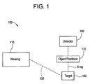
- Figure 1 illustrates an EBT imaging system formed in accordance with an
embodiment of the present invention.
- Figure 2 illustrates a portion of an electron beam housing formed in
accordance with an embodiment of the present invention.
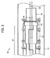
- Figure 3 illustrates an electrode assembly formed in accordance with an
embodiment of the present invention.
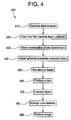
- Figure 4 depicts a flow diagram for a method for correcting spherical
aberration in an electron beam according to an embodiment of the present
invention.
- Figure 5 illustrates a graph depicting spherical aberrations versus PIE voltage
based on grounded tube radius in accordance with an embodiment of the
present invention.
- Figure 6 depicts spherical aberration of the electron beam versus grounded
tube radius based on PIE voltage in accordance with an embodiment of the
present invention.
- Figure 7 compares a conventional system using PIE to an improved system
using PIE with a grounded tube in accordance with an embodiment of the
present invention.
- Figure 8 illustrates the positioning of the PIE and the grounded tube in the
EBT imaging system according to an embodiment of the present invention.
-
-
For the purpose of illustration only, the following detailed description
references a certain embodiment of an Electron Beam Tomography (EBT)
imaging system. It is understood that the present invention may be used with
other imaging systems and other electron beam systems.
-
Figure 1 illustrates an EBT imaging system 100 formed in accordance with an
embodiment of the present invention. The EBT system 100 includes a
housing 110, a target 160, an object positioner 170, and a detector 180. As
illustrated in greater detail in Figure 2, the housing 110 includes an electron
source 120, an electrode assembly 140, and beam optics 150. As shown in
Figure 3, the electrode assembly 140 includes an ion clearing electrode (ICE)
142, a Positive Ion Electrode (PIE) 144, and a grounded tube 146.
-
The electron source 120 provides a source of electrons that may be used to
form an electron beam 105 for use in imaging. The electron beam 105 from
the electron source 120 is used to produce radiation, such as x-ray radiation,
for use in imaging at the target 160. The electron source 120 may be
connected to a voltage generator (not pictured) and is used to generate an
electron beam 105. For example, the electron beam 105 is generated at the
cathode of the electron source 120 in response to a -130 kV voltage from the
voltage generator.
-
The electrode assembly 140 controls positive ions in an upstream region of
the electron beam 105 using the ICE 142, washer-shaped PIE 144, and
grounded tube 146. For example, the electrode assembly 140 may control
positive ions by surrounding and subjecting an electron beam 105 to electric
fields transverse to the electron beam 105 velocity that advantageously
extract positive ions from the electron beam 105 while minimizing net electron
beam 105 deflection.
-
The ion clearing electrode (ICE) 142 removes positive ions from the electron
beam 105. The ICE 142 may be a multi-sided rotatable field ion clearing
electrode (RICE), multiple multi-sided ion clearing electrodes (ICE), a periodic
axial field ion controlling electrode (PICE), or a single potential ion clearing
electrode (SPICE), for example. The ICE 140 is terminated by the PIE or ion
trap 144.
-
The SPICE, for example, extracts positive ions from the electron beam 105
using an ion clearing electrode assembly that is operable from a single source
of operating potential and produces essentially zero net beam deflection and
displacement. The SPICE is normally installed inside a magnetic solenoid
(focusing) lens, concentric about the Z-axis of the system 100, and uses two
basic arrays of electrode cross-sections that alternate along the Z-axis to
generate electric fields to cancel or minimize focusing and aberration-producing
fields around the electron beam 105.
-
The PIE 144 or ion trap prevents ions generated by residual gas in the
electron beam 105 downstream from the ICE 142 from drifting upstream into
the ICE 142. The ions are accumulated in the downstream portion of the
electron beam 105 to neutralize space-charge exhibited by the electron beam
105. The PIE 144 may be a washer-shaped electrode. A voltage potential
applied to the PIE 144 produces a paraboloidal neutralization boundary 148 to
form between the space-charge-dominated portion of the electron beam 105
in the ICE 142 and the neutralized portion of the electron beam 105
downstream. Ions accumulate downstream from the paraboloidal
neutralization boundary 148. The accumulated ions neutralize the electron
beam 105 and cause the electron beam 105 to be self-focusing.
-
The paraboloidal boundary 148 between the space-charged beam and the
neutralized beam causes beam 105 self-focusing forces which are
proportional to beam 105 radius cubed. Focusing forces that are proportional
to the beam 105 radius cubed are a classical condition for spherical
aberrations. The magnitude of the spherical aberrations is proportional to the
axial extent of the neutralization boundary 148. The extent the boundary 148
is controlled by the voltage applied to the PIE 144 and by the dimensions of
the PIE 144 and the grounded tube 146. A voltage potential applied to the
PIE 144 may be used to cancel or correct spherical aberrations produced by
other beam line elements, such as the electron source 120, by modifying the
paraboloidal neutralization boundary 148 (i.e., reducing the extent of the
boundary 148).
-
The grounded tube 146 shifts the range of spherical aberration correction of
the PIE 144 to lower values using an applied potential. The grounded tube
146 is a metal tube, such as aluminum, non-magnetic stainless steel, or
copper, for example. The grounded tube 146 is grounded in the system 100
by attachment to an ICE support frame 145 or the inside wall of the housing or
beam tube 110, for example. In an embodiment, the grounded tube 146 is an
aluminum tube having a length of 80 mm, a radius of 30 mm, and a thickness
of 1.6 mm. The dimensions, composition, and positioning of the grounded
tube 146 may vary.
-
The grounded tube 146 is positioned downstream from the PIE 144 in the
beam tube 110. The grounded tube 146 is sufficiently spaced from the PIE
144 to prevent arcing between the grounded tube 146 and the PIE 144 (for
example, spacing of a few millimeters). For example, a spacing of two
millimeters or more may prevent arcing between the grounded tube 146 and
the PIE 144 at an applied voltage potential of 1000 V. In a certain
embodiment, the space between the grounded tube 146 and the PIE 144 is
smaller than the grounded tube 146 and the PIE 144 radii (for example, less
than 6 mm). In a certain embodiment, the end of the grounded tube 146
facing the downstream region of the electron beam 105 is several electron
beam 105 diameters beyond the paraboloidal neutralization boundary 148
formed by the PIE 144.
-
Figure 8 illustrates the positioning of the PIE 144 and the grounded tube 146
in the EBT imaging system 100 according to an embodiment of the present
invention. The grounded tube 146 and the PIE 144 are centered
symmetrically around the axis along which the electron beam 105 travels
through the beam tube 110. The PIE 144 and the grounded tube 146 are
mounted in the ICE support frame 145 within the beam tube 110. in an
embodiment, the grounded tube 146 and the PIE 144 are each attached to
the support frame 145 by three fasteners that are spaced 120 degrees apart.
-
When the grounded tube 146 is positioned downstream from the PIE 144, the
radius of the grounded tube 146 (for example, 30 mm) becomes the effective
"electrical" radius of the beam tube or housing 110 surrounding the electron
beam 105 downstream from the PIE 144. That is, when the grounded tube
146 is present downstream from the PIE 144, the grounded tube 146
becomes the beam tube 110 from an electrostatic perspective. However,
from a vacuum or physical perspective, the beam tube 110 has a larger radius
than the grounded tube 146 (for example, 76 mm). If the grounded tube 146
is not present, the electrical radius (radius in an electrostatic sense) and the
vacuum/physical radius of the beam tube 110 are the same (for example, 76
mm). The beam tube provides vacuum pumping for the ICE 142/PIE 144
system.
-
In certain embodiments, the electrostatic potential at the paraboloidal
neutralization boundary 148 produced by the PIE 144 is equal to the voltage
potential due to the PIE 144 plus the voltage potential of the electron beam
105. Downstream from the PIE 144, the magnitude of the voltage potential of
the electron beam 105 decreases as the radius of the grounded tube 146
decreases. If the grounded tube 146 radius were reduced to equal the
electron beam 105 radius (i.e., the beam 105 would touch the grounded tube
146), the voltage potential of the edge of the electron beam 105 would be
zero.
-
Spherical aberrations of the electron beam 105 are affected by the voltage
potential of the PIE 144, the radius of the PIE 144, and the radius of the beam
tube 110. Changes to the voltage potential applied to the PIE 144 may be
impractical beyond a certain threshold. Modification of the PIE 144 aperture
may also be of limited effectiveness after a certain threshold. The introduction
of the grounded tube 146 effectively reduces the radius of the portion of the
beam tube 110 downstream from the PIE 144 in electrical terms, while leaving
the physical beam tube 110 radius unchanged. That is, the effective electrical
radius of the beam tube 110 conforms to the physical radius of the grounded
tube 146. The grounded tube 146 restricts the potential of the electron beam
105 and helps to minimize spherical aberrations downstream from the PIE
144. As further described below in relation to Figures 5, 6, and 7, for the
same spherical aberration (the same neutralization boundary length, for
example), the potential due to the PIE 144 and the voltage applied to the PIE
144 decrease as the radius of the grounded tube 146 and the magnitude of
the potential due to the beam 105 decrease.
-
The electron beam 105 is focused by the beam optics 150. The beam optics
150 may adjust radius, angle, and/or timing of the electron beam 105, for
example. The beam optics 150 may include a quadrupole coil, a deflection
coil, and a magnetic lens. The coils focus and shape the electron beam 105
to impact the target 160 for use in imaging.
-
The target 160 produces radiation, such as x-ray radiation, upon contact by
the electron beam 105. The location at which the electron beam 105 strikes
the target 160 is referred to as the beam spot. The target 160 is struck by the
beam 105 at the beam spot, and x-rays are produced. The x-rays travel away
from the target 160. The target 160 may be a metal target, such as a
tungsten target, for example.
-
The object positioner 170 positions an object to be imaged at least partially in
the path of the radiation emitted from the target 160 at the beam spot. The
object on the object positioner 170 is irradiated as the x-rays travel from the
target 160. The object positioner 170 may be movable or immovable and may
position the object horizontally and/or vertically.
-
The detector 180 detects radiation impinging upon it from the target 160. X-rays
from the target 160 irradiate the object on the object positioner 170 and
then strike the detector 180. X-rays passing through the object are attenuated
to varying degrees depending on the density of the matter through which the
x-rays pass. X-rays impacting on the detector 180 generate an electrical
response corresponding to the intensity of the attenuated radiation. A
diagnostic image is formed from the electrical response.
-
In operation, the voltage generator and the electron source 120 generate an
electron beam 105 from the cathode of the electron source 120. The electron
beam 105 passes from the cathode of the electron source 120 to the
electrode assembly 140. Within the electrode assembly 140, electrodes in the
ICE 142 produce electric fields that remove positive ions from the electron
beam 105. Thus, the electron beam 105 is charged within the ICE 142.
-
Next, the electron beam 105 enters the PIE 144. The PIE 144 traps or
confines ions to the downstream portion of the electron beam 105. The PIE
144 produces a boundary 148 that blocks the ions. The ions neutralize the
electron beam 105 downstream from the ICE 142.
-
Spherical aberrations are introduced by ion clearing and ion trapping and by
the electron source 120, as well as other components. The PIE 144 voltage
controls the spherical aberrations due to ion trapping. The PIE 144 may
cancel spherical aberrations in the electron beam 105 due to other
components. However, if the degree of spherical aberrations to be cancelled
becomes excessive, a large voltage must be applied to the PIE 144 to correct
the spherical aberrations. The PIE 144 voltage may become too large.
However, with the introduction of the grounded tube 146, the PIE 144 and
grounded tube 146 cooperate to adjust the spherical aberration characteristics
and provide a wider range for correction of spherical aberrations.
-
When used alone, the PIE 144 has an inherent upper limit and lower limit to
its spherical aberration correction capabilities. The upper limit of correction is
extended by increasing the aperture or opening of the PIE 144. The lower
correction limit is extended by increasing the voltage applied to the PIE 144.
-
Without the grounded tube 146, a small extension of the lower limit requires
an increase in applied voltage by an order of magnitude. The grounded tube
146 allows extension of the lower limit of spherical aberration correction
based on the radius of the grounded tube 146 in relation to the beam tube 110
housing the electrode assembly 140.
-
After the electron beam 105 has passed through the PIE 144 and the
grounded tube 146 and the beam optical system 150, spherical aberration in
the electron beam 105 has been minimized. The PIE 144 with the grounded
tube 146 reduces the halo surrounding the electron beam 105 at the beam
spot caused by spherical aberrations. Thus, the electron beam 105 that
strikes the target 160 produces x-rays from the target 160 that possess a
reduced halo.
-
X-rays generated at the target 160 travel outwards through the object
positioner 170 and irradiate an object positioned on the object positioner 170.
The x-rays that are not blocked by the object then impinge upon the detector
180. Signals are generated based on the strength of the x-rays impacting the
detector 180. The signals are used to produce an image. X-rays with
reduced halo help to improve image quality in the resulting image.
-
Figure 4 depicts a flow diagram for a method 400 for correcting spherical
aberrations in the electron beam 105 according to an embodiment of the
present invention. First at step 410, an electron beam 105 is generated.
Next, at step 420, ions are cleared from the upstream electron beam 105
through electrical fields that are produced by the ICE 142. At step 430, ions
are allowed to accumulate in a downstream portion of the electron beam 105.
Ion accumulation beyond the paraboloidal neutralization boundary 148 occurs
automatically. Thus, the portion of the electron beam 105 downstream from
the neutralization boundary 148 is largely neutralized and contains a number
of ions equal to the number of electrons. For example, a washer-shaped ion
trap, such as the PIE 144, with an opening in the center, may be used to
create a paraboloidal boundary 148 blocking the ions from moving upstream.
-
However, ion trapping has limits in spherical aberration correction. Therefore,
at step 440, the correction limits of the ion trap, such as the PIE 144, are
shifted. For example, the upper limit of the PIE 144 may be adjusted by
adjusting the size of the opening or aperture in the PIE 144. Additionally, the
lower limit of spherical aberration correction of the PIE 144 may be adjusted
by placing a grounded tube 146 downstream from the PIE 144. As discussed
further below in relation to Figure 5, the dimensions of the grounded tube 146
decrease the limits of spherical aberration correction.
-
An upper limit of spherical aberration correction is increased by widening an
aperture of an ion trap, such as the PIE 144, through which an electron beam
105 passes. The ion trap allows ions to accumulate in the electron beam 105
at a downstream portion of the electron beam 105. A lower limit of spherical
aberration correction is expanded by positioning a grounded tube 146 beyond
the ion trap to shift the range of correction of the ion trap to lower values. The
dimensions of the grounded tube 146 affect electrical interaction between the
ion trap and the electron beam 105 and lower the range of spherical
aberration correction provided by the ion trap.
-
Then, at step 450, the corrected electron beam 105 is aimed and/or focused
by the beam optics 150. At step 460, the electron beam 105 impacts the
target 160 and produces x-rays. Next, at step 470, the x-rays travel from the
target 160 and pass through an object located on the object positioner 170,
irradiating the object. At step 480, the x-rays impinge upon the detector 180.
The x-rays produce signals at the detector 180 in proportion to the intensity
with which the x-rays arrive at the detector 180 after irradiating the object on
the object positioner 170. Finally, at step 490, the signals are used to
produce an image representative of the object through which the x-rays
passed.
-
Figure 5 illustrates a graph depicting spherical aberrations versus PIE 144
voltage based on different grounded tube 146 radii. Figure 5 shows a shift of
voltage for constant spherical aberrations as the grounded tube 146 radius
decreases. At a smaller physical grounded tube 146 radius, and thus a
smaller effective electrical radius of the beam tube 110, a lower voltage
potential applied to the PIE 144 achieves the same reduction of spherical
aberrations in the electron beam 105 as a higher voltage potential applied
with a larger effective electrical radius. In Figure 5, the spherical aberrations
at the edge of the electron beam 105 is the same at 0.2 diopter with a PIE 144
voltage of 710 V and a grounded tube 146 radius of 7.62 cm and with a PIE
144 voltage of 330 V and a grounded tube 146 radius of 3.0 cm. Thus, a
small grounded tube 146 radius allows a given reduction in spherical
aberration at a lower applied voltage potential.
-
Figure 6 depicts spherical aberration of the electron beam 105 versus
grounded tube 146 radius based on PIE 144 voltage. Figure 6 shows how
spherical aberration generally increases as the radius of the grounded tube
146 increases for a given voltage potential applied to the PIE 144. At a
constant voltage, a decrease in the radius of the grounded tube 146, and thus
a decrease in the effective electrical radius of the beam tube 110, allows for
an extended range of reduction in spherical aberrations of the electron beam
105. Figure 6 illustrates spherical aberration versus grounded tube 146
radius for a PIE 144 applied potential of 1000V and a minimum applied PIE
144 potential. For example, with a grounded tube 146 radius of 3.0cm,
spherical aberration correction of the electron beam 105 is 0.225 diopter at a
minimum PIE 144 voltage and 0.08 diopter at a PIE 144 voltage of 1000V.
-
Figure 7 compares a conventional system using PIE 144 to an improved
system using PIE 144 with a grounded tube 146 in accordance with an
embodiment of the present invention. Figure 7(a) illustrates a conventional
system using PIE 144 with a large radius rw between the center of the electron
beam 105 and the wall of the beam tube. Figure 7(b) graphs PIE 144
potential near the z-axis of the PIE 144 and the neutralization boundary 148
formed by voltage applied to the PIE 144. The voltage potential due to the
PIE 144 is shown with respect to distance along the z-axis. The PIE 144
voltage potential and the extent of the neutralization boundary 148 along the
z-axis of the electron beam 105 impact spherical aberrations within the
electron beam 105.
-
An improved PIE 144 with the grounded tube 146 is shown in Figure 7(c). As
shown in Figure 7(c), the radius rw is greatly reduced from the center of the
electron beam 105 to the wall of the grounded tube 146, rather than the wall
of the beam tube or housing 110. Additionally, the neutralization boundary
148 is formed by the PIE 144 closer to the PIE 144 than in the prior art and is
of reduced extent. By reducing the radius and shortening the extent of the
boundary 148 along the z-axis of the electron beam 105, spherical aberrations
may be reduced. The addition of the grounded tube 146 improves the
reduction and ease of reduction in spherical aberration of the electron beam
105 and, thus, improves resulting image quality as well.
-
For the sake of good order, various aspects of the invention are set out in the
following clauses: -
- 1. A method for correcting spherical aberration in an electron beam (105)
having an upstream region and a downstream region, said method
comprising:
- producing an electron beam (105, 400);
- removing ions from the electron beam (105) using electrical fields in
the upstream region of the electron beam (105, 400);
- allowing ions to accumulate in the downstream region of the electron
beam (105 using an ion trap (144) and a grounded tube (146, 400); and
- adjusting a range of spherical aberration correction of the ion trap (144)
with the grounded tube (146, 400).
- 2. The method of clause 1, further comprising adjusting an aperture in the
ion trap (144) to adjust the range of spherical aberration correction of the ion
trap (144).
- 3. The method of clause 1, further comprising applying a voltage to the
ion trap (144) to form a neutralization boundary (148) to trap the ions
accumulated in the downstream region of the electron beam (105).
- 4. The method of clause 3, wherein the voltage applied to the ion trap
(144) to form the neutralization boundary (148) decreases as a radius of the
grounded tube (146) decreases.
- 5. The method of clause 1, wherein the ion trap (144) comprises a
positive ion electrode (144).
- 6. The method of clause 1, wherein the electrical fields are generated by
an ion clearing electrode (142).
- 7. A computed tomography system, said system comprising:
- an electron beam source (120) for generating an electron beam (105);
- an ion clearing electrode (142) for removing ions from said electron
beam (105) using electrical fields;
- an ion trap (144) for allowing ions to accumulate in a downstream
region of said electron beam (105) so that said ions do not drift upstream;
- a beam tube (110) for housing said ion trap (144); and
- a grounded tube (146), located downstream of said ion trap (144), said
grounded tube (146) being electrically grounded, an effective electrical radius
of said beam tube (110) conforming to a physical radius of said grounded tube
(146) to reduce spherical aberration in said electron beam (105).
- 8. The system of clause 7, wherein said grounded tube (146) comprises a
non-magnetic grounded tube (146).
- 9. The system of clause 7, wherein a radius of said grounded tube (146)
extends a lower limit of spherical aberration correction of said ion trap (144).
- 10. The system of clause 7, wherein said ion trap (144) comprises a
positive ion electrode (144), said positive ion electrode (144) including an
aperture through which said electron beam (105) passes.
- 11. The system of clause 10, wherein size of said aperture is adjusted to
adjust an upper limit of spherical aberration correction of said ion trap (144).
- 12. The system of clause 7, wherein said ion trap (144) uses a voltage to
create a neutralization boundary (148) to trap ions in said downstream region
of said electron beam (105).
- 13. The system of clause 12, wherein said grounded tube (146) decreases
said voltage applied to said ion trap (144) for a certain spherical aberration
correction.
- 14. The system of clause 7, further comprising beam optics (150) to at
least one of aim and focus said electron beam (105).
- 15. The system of clause 7, further comprising a target (160) producing x-ray
radiation in response to impact by said electron beam (105).
- 16. The system of clause 15, further comprising a detector (180) for
detecting said x-ray radiation produced at said target (160).
- 17. A method for reducing spherical aberration in a computed tomography
scanner, said method comprising:
- increasing an upper limit of spherical aberration correction by widening
an aperture of an ion trap (144), the ion trap (144) allowing ions to accumulate
in an electron beam (105) at a downstream portion of the electron beam (105)
using an applied potential;
- extending a lower limit of spherical aberration correction by positioning
a grounded tube (146) beyond the ion trap (144); and
- passing an electron beam (105) through the ion trap (144) and the
grounded tube (146).
- 18. The method of clause 17, wherein the grounded tube (146) decreases
the applied potential for spherical aberration correction.
- 19. A system for correcting spherical aberration in an electron beam (105),
said system comprising:
- an ion trap (144) having a voltage for applying a potential to an electron
beam (105) to allow ions to accumulate in said electron beam (105) in a
portion of said electron beam (105) downstream from said ion trap (144) in
order to reduce spherical aberration in said electron beam (105); and
- a grounded tube (146) for extending a range of spherical aberration
reduction in relation to at least one of dimension and position of said
grounded tube (146), said grounded tube (146) reducing said voltage applied
to said ion trap (144).
- 20. The system of clause 19, wherein said voltage applied to said ion trap
(144) decreases as a radius of said grounded tube (146) decreases.
- 21. The system of clause 19, wherein said range of spherical aberration
reduction expands as size of an opening in said ion trap (144) expands.
-