EP1414681B1 - Safety belt winder comprising a power limitation system which can be actuated according to the strip of belt pulled out - Google Patents
Safety belt winder comprising a power limitation system which can be actuated according to the strip of belt pulled out Download PDFInfo
- Publication number
- EP1414681B1 EP1414681B1 EP02743104A EP02743104A EP1414681B1 EP 1414681 B1 EP1414681 B1 EP 1414681B1 EP 02743104 A EP02743104 A EP 02743104A EP 02743104 A EP02743104 A EP 02743104A EP 1414681 B1 EP1414681 B1 EP 1414681B1
- Authority
- EP
- European Patent Office
- Prior art keywords
- switching
- belt
- switching device
- belt shaft
- torque rod
- Prior art date
- Legal status (The legal status is an assumption and is not a legal conclusion. Google has not performed a legal analysis and makes no representation as to the accuracy of the status listed.)
- Expired - Lifetime
Links
Images
Classifications
-
- B—PERFORMING OPERATIONS; TRANSPORTING
- B60—VEHICLES IN GENERAL
- B60R—VEHICLES, VEHICLE FITTINGS, OR VEHICLE PARTS, NOT OTHERWISE PROVIDED FOR
- B60R22/00—Safety belts or body harnesses in vehicles
- B60R22/34—Belt retractors, e.g. reels
- B60R22/341—Belt retractors, e.g. reels comprising energy-absorbing means
-
- B—PERFORMING OPERATIONS; TRANSPORTING
- B60—VEHICLES IN GENERAL
- B60R—VEHICLES, VEHICLE FITTINGS, OR VEHICLE PARTS, NOT OTHERWISE PROVIDED FOR
- B60R21/00—Arrangements or fittings on vehicles for protecting or preventing injuries to occupants or pedestrians in case of accidents or other traffic risks
- B60R21/01—Electrical circuits for triggering passive safety arrangements, e.g. airbags, safety belt tighteners, in case of vehicle accidents or impending vehicle accidents
- B60R21/015—Electrical circuits for triggering passive safety arrangements, e.g. airbags, safety belt tighteners, in case of vehicle accidents or impending vehicle accidents including means for detecting the presence or position of passengers, passenger seats or child seats, and the related safety parameters therefor, e.g. speed or timing of airbag inflation in relation to occupant position or seat belt use
- B60R21/01512—Passenger detection systems
- B60R21/01516—Passenger detection systems using force or pressure sensing means
- B60R21/0152—Passenger detection systems using force or pressure sensing means using strain gauges
-
- B—PERFORMING OPERATIONS; TRANSPORTING
- B60—VEHICLES IN GENERAL
- B60R—VEHICLES, VEHICLE FITTINGS, OR VEHICLE PARTS, NOT OTHERWISE PROVIDED FOR
- B60R22/00—Safety belts or body harnesses in vehicles
- B60R22/34—Belt retractors, e.g. reels
- B60R22/341—Belt retractors, e.g. reels comprising energy-absorbing means
- B60R22/3413—Belt retractors, e.g. reels comprising energy-absorbing means operating between belt reel and retractor frame
-
- B—PERFORMING OPERATIONS; TRANSPORTING
- B60—VEHICLES IN GENERAL
- B60R—VEHICLES, VEHICLE FITTINGS, OR VEHICLE PARTS, NOT OTHERWISE PROVIDED FOR
- B60R22/00—Safety belts or body harnesses in vehicles
- B60R22/28—Safety belts or body harnesses in vehicles incorporating energy-absorbing devices
- B60R2022/286—Safety belts or body harnesses in vehicles incorporating energy-absorbing devices using deformation of material
- B60R2022/287—Safety belts or body harnesses in vehicles incorporating energy-absorbing devices using deformation of material of torsion rods or tubes
-
- B—PERFORMING OPERATIONS; TRANSPORTING
- B60—VEHICLES IN GENERAL
- B60R—VEHICLES, VEHICLE FITTINGS, OR VEHICLE PARTS, NOT OTHERWISE PROVIDED FOR
- B60R22/00—Safety belts or body harnesses in vehicles
- B60R22/28—Safety belts or body harnesses in vehicles incorporating energy-absorbing devices
- B60R2022/288—Safety belts or body harnesses in vehicles incorporating energy-absorbing devices with means to adjust or regulate the amount of energy to be absorbed
-
- B—PERFORMING OPERATIONS; TRANSPORTING
- B60—VEHICLES IN GENERAL
- B60R—VEHICLES, VEHICLE FITTINGS, OR VEHICLE PARTS, NOT OTHERWISE PROVIDED FOR
- B60R21/00—Arrangements or fittings on vehicles for protecting or preventing injuries to occupants or pedestrians in case of accidents or other traffic risks
- B60R21/01—Electrical circuits for triggering passive safety arrangements, e.g. airbags, safety belt tighteners, in case of vehicle accidents or impending vehicle accidents
- B60R21/015—Electrical circuits for triggering passive safety arrangements, e.g. airbags, safety belt tighteners, in case of vehicle accidents or impending vehicle accidents including means for detecting the presence or position of passengers, passenger seats or child seats, and the related safety parameters therefor, e.g. speed or timing of airbag inflation in relation to occupant position or seat belt use
- B60R21/01512—Passenger detection systems
- B60R21/01544—Passenger detection systems detecting seat belt parameters, e.g. length, tension or height-adjustment
- B60R21/01548—Passenger detection systems detecting seat belt parameters, e.g. length, tension or height-adjustment sensing the amount of belt winded on retractor
-
- B—PERFORMING OPERATIONS; TRANSPORTING
- B60—VEHICLES IN GENERAL
- B60R—VEHICLES, VEHICLE FITTINGS, OR VEHICLE PARTS, NOT OTHERWISE PROVIDED FOR
- B60R22/00—Safety belts or body harnesses in vehicles
- B60R22/34—Belt retractors, e.g. reels
- B60R22/36—Belt retractors, e.g. reels self-locking in an emergency
- B60R22/415—Belt retractors, e.g. reels self-locking in an emergency with additional means allowing a permanent locking of the retractor during the wearing of the belt
Definitions
- the invention relates to a safety belt with a stored in a housing belt shaft as a carrier a developable and developable on it Webbing, wherein the belt retractor a multi-level working force limiting device with a Torsion bar and a torsion bar in different clamping length with the belt shaft having coupling device and wherein the measure of the from the Gurtwelle unwound webbing for the Circuit of the force limiting device is used.
- a seat belt retractor with the aforementioned features is known from DE 27 27 470 A1.
- the known Seat belt retractor has a torsion bar as Force limiting device on, at its one end rotatably connected to the shaft lock and on coupled to the belt shaft at its other end is such that even when triggered shaft lock is the Belt shaft with twisting of the torsion bar around can continue to turn a certain amount.
- the known belt retractor a device for continuous change of the clamping length of the Torsionsstabes, which in one embodiment of the previously known belt retractor depending on the length the extended webbing should be controllable by a the clamping length defining sliding sleeve on a Gear is connected to the belt shaft.
- DE 197 80 583 C shows a seat belt retractor with a torsion bar, its effective length and thickness by pyrotechnic working Switching devices are changeable.
- the invention is therefore based on the object, a Seat belt retractor with the generic features with high reliability in its construction too simplify.
- the invention provides in detail that a two-stage Torsion bar with a pyrotechnic working Switching device provided and a via a Reduction gear connected to the belt shaft Ratchet is arranged, wherein the ratchet via a Part of its circumference a gearing to the intervention of Reduction gear and another part of his Circumference against a switch pin on the Switching device for the torsion bar connected Electric switch has applied switching contour and the Switching contour with a connection or disconnection of the Switching device for the torsion bar effecting course is trained.
- the invention is advantageously characterized characterized in that only a two-stage torsion bar as Force limiting device is proposed because so the different body sizes with large occupants or in small women, adolescents and children in each case adequately take account of the defined response range is.
- a two-stage torsion bar is also a known pyrotechnic Switching device for the two applicable clamping lengths the torsion bar used by means of which in a very reliable manner the respective clamping length of the Torsionsstabes is set, the pyrotechnic Switching device in a sensed accident depending on the Measure of the belt strap unwound from the belt shaft is triggered or not.
- the relevant Control of the release readiness of the pyrotechnic Switching device according to the invention is characterized in that the according to the prevailing webbing extension in one Positioned ratchet wheel trained on it Switching contour the switching pin of an electric switch acted upon, wherein the electric switch the Tripping readiness of the pyrotechnic switching device as defined above. This is one simple construction and safe operation of the Guaranteed according to the invention equipped belt retractor.
- the switching contour starting from the at full wound up webbing furnished position of Wegrades a first section to the plant in this Position a deactivation of the release of the pyrotechnic switching device causing switching pin and a second, to the first section subsequent and upon rotation of the belt shaft of the Weg. has overrunning section, wherein in the Position applied to the second section of the switching contour the switching pin, the pyrotechnic switching device is triggerable, and that the second section, a third Section of the switching contour for the contact pin connects and the switch pin in his on the third Section of the switching contour adjoining position the Triggering the pyrotechnic switching device disabled.
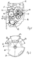
- a known belt retractor has a U-shaped Housing on, in the side housing plates, of which in Figure 1, a housing plate 10 can be seen, a Belt shaft 11 is stored. As can be seen from FIG. 1, the belt shaft 11 carries a firmly connected with her Worm gear 13. On the side housing plate 10 is a vehicle-sensitive sensor 12 is arranged, whose Function with self-locking belt retractors from the state The technique is well known.
- the shaft gear 13 a from two other gears existing reduction gear 15 is connected, which is a rotatably mounted on the housing plate 10 Ratchet 16 acted upon.
- the ratchet wheel 16 via a part of its outer periphery with an outer toothing 20th Mistake.
- the ratchet 16 is an electric switch 17th assigned, from which one shown in Figure 2 Stick pin 25 protrudes and on one of the ratchet 16th trained switching contour 21 is guided, wherein the Electric switch 17 with a switch housing 18 for the pyrotechnically operated switching device for adjustment the clamping length of the force limiting device forming, not shown in detail torsion bar is coupled.
- the belt retractor also has a Connection 19 for a coming from the vehicle Energy supply on.
- Switching contour 21 formed with three areas, namely a first region 22, a second region 23 and a third area 24, wherein the areas 22, 23, 24 at the Pivoting the ratchet wheel 16 of the adjacent thereto stationary switching pin 25 are run over.
- the assignment the switching wheel 16 is affected in such a way that in the first area 22 a position of the switching pin 25th is effected, in which the electric switch 17 a Deactivation of the pyrotechnic switching device so in case of a sensed accident the pyrotechnic switching device is not triggered.
- This first region 22 corresponds to a position of Belt shaft 11 with fully or almost fully wound Webbing, so when stored seat belt or only slightly pulled webbing, and in this Belt pulley position is a trigger of Switching device not required or not desired.
Abstract
Description
Die Erfindung betrifft einen Sicherheitsgurtaufroller mit einer in einem Gehäuse gelagerten Gurtwelle als Träger eines darauf aufwickelbaren und davon abwickelbaren Gurtbandes, wobei der Gurtaufroller eine mehrstufig arbeitende Kraftbegrenzungseinrichtung mit einem Torsionsstab und einer den Torsionsstab in unterschiedlicher Einspannlänge mit der Gurtwelle kuppelnden Schaltvorrichtung aufweist und wobei das Maß des von der Gurtwelle abgewickelten Gurtbandes für die Schaltung der Kraftbegrenzungseinrichtung herangezogen ist.The invention relates to a safety belt with a stored in a housing belt shaft as a carrier a developable and developable on it Webbing, wherein the belt retractor a multi-level working force limiting device with a Torsion bar and a torsion bar in different clamping length with the belt shaft having coupling device and wherein the measure of the from the Gurtwelle unwound webbing for the Circuit of the force limiting device is used.
Ein Sicherheitsgurtaufroller mit den vorgenannten Merkmalen ist aus der DE 27 27 470 A1 bekannt. Der bekannte Sicherheitsgurtaufroller weist einen Torsionsstab als Kraftbegrenzungseinrichtung auf, der an seinem einen Ende drehfest an die Wellenverriegelung angeschlossen und an seinem anderen Ende an die Gurtwelle gekoppelt ist derart, daß auch bei ausgelöster Wellenverriegelung sich die Gurtwelle unter Verdrillung des Torsionsstabes noch um einen gewissen Betrag weiterdrehen kann. Da die Einstellung des Kraftbegrenzungsniveaus in Abhängigkeit insbesondere von der Größe eines Fahrzeuginsassen erfolgen soll, weist der bekannte Gurtaufroller eine Vorrichtung zur kontinuierlichen Veränderung der Einspannlänge des Torsionsstabes auf, die in einer Ausführungsform des vorbekannten Gurtaufrollers in Abhängigkeit von der Länge des ausgezogenen Gurtbandes steuerbar sein soll, indem eine die Einspannlänge festlegende Schiebehülse über ein Getriebe mit der Gurtwelle verbunden ist.A seat belt retractor with the aforementioned features is known from DE 27 27 470 A1. The known Seat belt retractor has a torsion bar as Force limiting device on, at its one end rotatably connected to the shaft lock and on coupled to the belt shaft at its other end is such that even when triggered shaft lock is the Belt shaft with twisting of the torsion bar around can continue to turn a certain amount. Because the setting the force limitation level depending in particular should be made of the size of a vehicle occupant, points the known belt retractor a device for continuous change of the clamping length of the Torsionsstabes, which in one embodiment of the previously known belt retractor depending on the length the extended webbing should be controllable by a the clamping length defining sliding sleeve on a Gear is connected to the belt shaft.
Mit dem bekannten Sicherheitsgurtaufroller ist der Nachteil verbunden, daß die Schiebehülse keine ausreichende Sicherheit für die Festlegung der Einspannlänge des Torsionsstabes darstellt, und im übrigen die Mechanik für eine kontinuierliche Anpassung der Einspannlänge des Torsionsstabes an die Umdrehungszahl der Gurtwelle und damit an den jeweils herrschenden Gurtbandauszug aufwendig ist.With the known seat belt retractor is the disadvantage connected, that the sliding sleeve is not sufficient Safety for the determination of the clamping length of the Torsionsstabes represents, and otherwise the mechanics for a continuous adjustment of the clamping length of the Torsionsstabes to the number of revolutions of the belt shaft and so consuming the prevailing Gurtbandauszug is.
Die DE 197 80 583 C zeigt einen Sicherheitsgurtaufroller mit einem Torsionsstab, dessen wirksame Länge und Dicke durch pyrotechnisch arbeitende Schaltvorrichtungen veränderbar sind.DE 197 80 583 C shows a seat belt retractor with a torsion bar, its effective length and thickness by pyrotechnic working Switching devices are changeable.
Der Erfindung liegt daher die Aufgabe zugrunde, einen Sicherheitsgurtaufroller mit den gattungsgemäßen Merkmalen bei hoher Betriebssicherheit in seinem Aufbau zu vereinfachen.The invention is therefore based on the object, a Seat belt retractor with the generic features with high reliability in its construction too simplify.
Die Lösung dieser Aufgabe ergibt sich einschließlich vorteilhafter Ausgestaltungen und Weiterbildungen der Erfindung aus dem Inhalt der Patentansprüche, welche dieser Beschreibung nachgestellt sind.The solution to this problem arises including advantageous embodiments and further developments of Invention from the content of the claims, which of these Description are adjusted.
Die Erfindung sieht im einzelnen vor, daß ein zweistufiger Torsionsstab mit einer pyrotechnisch arbeitenden Schaltvorrichtung vorgesehen und ein über ein Untersetzungsgetriebe an die Gurtwelle angeschlossenes Schaltrad angeordnet ist, wobei das Schaltrad über einen Teil seines Umfangs eine Verzahnung zum Eingriff des Untersetzungsgetriebes und über einen weiteren Teil seines Umfangs eine gegen einen Schaltstift eines an die Schaltvorrichtung für den Torsionsstab angeschlossenen Elektroschalters anliegende Schaltkontur aufweist und die Schaltkontur mit einem die Zuschaltung oder Abschaltung der Schaltvorrichtung für den Torsionsstab bewirkenden Verlauf ausgebildet ist.The invention provides in detail that a two-stage Torsion bar with a pyrotechnic working Switching device provided and a via a Reduction gear connected to the belt shaft Ratchet is arranged, wherein the ratchet via a Part of its circumference a gearing to the intervention of Reduction gear and another part of his Circumference against a switch pin on the Switching device for the torsion bar connected Electric switch has applied switching contour and the Switching contour with a connection or disconnection of the Switching device for the torsion bar effecting course is trained.
Zunächst ist die Erfindung in vorteilhafter Weise dadurch geprägt, daß lediglich ein zweistufiger Torsionsstab als Kraftbegrenzungseinrichtung vorgeschlagen ist, weil damit den unterschiedlichen Körpergrößen bei großen Insassen bzw. bei kleinen Frauen, Jugendlichen und Kindern in dem jeweils festgelegten Ansprechbereich ausreichend Rechnung zu tragen ist. Mit der Reduktion auf einen zweistufigen Torsionsstab ist auch eine an sich bekannte pyrotechnische Schaltvorrichtung für die beiden geltenden Einspannlängen des Torsionsstabes einsetzbar, mittels derer in einer sehr betriebssicheren Weise die jeweilige Einspannlänge des Torsionsstabes festzulegen ist, wobei die pyrotechnische Schaltvorrichtung bei einem sensierten Unfall je nach dem Maß des von der Gurtwelle abgewickelten Gurtbandes ausgelöst wird oder nicht. Wird die pyrotechnische Schaltvorrichtung nicht ausgelöst, wirkt das entsprechend hoch eingestellte Belastungsniveau, wie es für große Fahrzeuginsassen zweckmäßig ist, während bei Auslösung der Schaltvorrichtung die Einspannlänge des Torsionsstabes verändert und ein entsprechend niedrigeres Kraftbegrenzungsniveau eingestellt wird. Die diesbezügliche Steuerung der Auslösebereitschaft der pyrotechnischen Schaltvorrichtung erfolgt erfindungsgemäß dadurch, daß das entsprechend dem herrschenden Gurtbandauszug in eine Stellung gebrachte Schaltrad über eine an ihm ausgebildete Schaltkontur den Schaltstift eines Elektroschalters beaufschlagt, wobei der Elektroschalter die Auslösebereitschaft der pyrotechnischen Schaltvorrichtung in dem vorstehend erläuterten Sinne festlegt. Damit sind ein einfacher Aufbau und eine sichere Funktion des erfindungsgemäß ausgerüsteten Gurtaufrollers gewährleistet.First, the invention is advantageously characterized characterized in that only a two-stage torsion bar as Force limiting device is proposed because so the different body sizes with large occupants or in small women, adolescents and children in each case adequately take account of the defined response range is. With the reduction to a two-stage torsion bar is also a known pyrotechnic Switching device for the two applicable clamping lengths the torsion bar used by means of which in a very reliable manner the respective clamping length of the Torsionsstabes is set, the pyrotechnic Switching device in a sensed accident depending on the Measure of the belt strap unwound from the belt shaft is triggered or not. Will the pyrotechnic Switching device not triggered, this acts accordingly High set load level, as is great Vehicle occupant is expedient, while triggering the Switching device, the clamping length of the torsion bar changed and a correspondingly lower Force limit level is set. The relevant Control of the release readiness of the pyrotechnic Switching device according to the invention is characterized in that the according to the prevailing webbing extension in one Positioned ratchet wheel trained on it Switching contour the switching pin of an electric switch acted upon, wherein the electric switch the Tripping readiness of the pyrotechnic switching device as defined above. This is one simple construction and safe operation of the Guaranteed according to the invention equipped belt retractor.
Im einzelnen ist zur Festlegung der Ansprechbereitschaft nach einem Ausführungsbeispiel der Erfindung vorgesehen, daß die Schaltkontur ausgehend von der bei voll aufgewickeltem Gurtband eingerichteten Stellung des Schaltrades einen ersten Abschnitt zur Anlage des in dieser Stellung eine Deaktivierung der Auslösung der pyrotechnischen Schaltvorrichtung bewirkenden Schaltstiftes aufweist und einen zweiten, an den ersten Abschnitt anschließenden und bei Drehung der Gurtwelle von dem Schaltstift überfahrenden Abschnitt aufweist, wobei in der am zweiten Abschnitt der Schaltkontur anliegenden Stellung des Schaltstiftes die pyrotechnische Schaltvorrichtung auslösbar ist, und daß an den zweiten Abschnitt ein dritter Abschnitt der Schaltkontur zur Anlage des Schaltstiftes anschließt und der Schaltstift in seiner an dem dritten Abschnitt der Schaltkontur anliegenden Stellung die Auslösung der pyrotechnischen Schaltvorrichtung deaktiviert. Mit der Aufteilung der Schaltkontur in drei Bereiche ist dem Umstand Rechnung getragen, daß bei vollständig abgelegtem Gurtband bzw. nur leicht ausgezogenem Gurtband eine Auslösung der pyrotechnischen Schaltvorrichtung nicht erfolgen soll. Wird das Gurtband mit einem Maß ausgezogen, welches bei kleineren Fahrzeuginsassen üblich ist, wird über die entsprechende Stellung des an der Schaltkontur anliegenden Schaltstiftes die Auslösebereitschaft der pyrotechnischen Schaltvorrichtung herbeigeführt, so daß bei.einem sensierten Unfall die Schaltvorrichtung anspricht. Wird das Gurtband von großen Fahrzeuginsassen weiter ausgezogen, bewegt sich der Schaltstift längs des dritten Abschnittes der Schaltkontur, und in dieser Stellung wird die Auslösebereitschaft der pyrotechnischen Schaltvorrichtung wiederum deaktiviert, so daß das hoch eingestellte Kraftbegrenzungsniveau Wirkung entfaltet.Specifically, to determine the responsiveness provided according to an embodiment of the invention, that the switching contour starting from the at full wound up webbing furnished position of Schaltrades a first section to the plant in this Position a deactivation of the release of the pyrotechnic switching device causing switching pin and a second, to the first section subsequent and upon rotation of the belt shaft of the Schaltstift has overrunning section, wherein in the Position applied to the second section of the switching contour the switching pin, the pyrotechnic switching device is triggerable, and that the second section, a third Section of the switching contour for the contact pin connects and the switch pin in his on the third Section of the switching contour adjoining position the Triggering the pyrotechnic switching device disabled. With the distribution of the switching contour in three Areas are taken into account the fact that at completely removed webbing or only lightly undressed webbing triggering the pyrotechnic Switching device should not be done. Will the webbing pulled out with a measure, which in smaller Vehicle occupants is common, is about the corresponding Position of the voltage applied to the switching contour switch pin the readiness to release the pyrotechnic Switching device brought about so that bei.einem sensed accident the switching device responds. Will that be Webbing continued to be pulled out by large vehicle occupants, the switching pin moves along the third section the switching contour, and in this position, the Tripping readiness of the pyrotechnic switching device deactivated again, so that the high set Kraftbegrenzungsniveau unfolded effect.
In der Zeichnung ist ein Ausführungsbeispiel der Erfindung wiedergegeben, welches nachstehend beschrieben ist. Es zeigen:
- Fig. 1
- die Systemseite eines Sicherheitsgurtaufrollers mit Ansteuerung der Kraftbegrenzungseinrichtung in Seitenansicht,
- Fig. 2
- das Schaltrad als Bestandteil der Steuerung in einer vergrößerten Darstellung.
- Fig. 1
- the system side of a seat belt retractor with control of the force limiting device in side view,
- Fig. 2
- the ratchet wheel as part of the controller in an enlarged view.
Ein an sich bekannter Gurtaufroller weist ein U-förmiges
Gehäuse auf, in dessen seitlichen Gehäuseplatten, von denen
in Figur 1 eine Gehäuseplatte 10 zu erkennen ist, eine
Gurtwelle 11 gelagert ist. Wie sich aus Figur 1 ergibt,
trägt die Gurtwelle 11 ein fest mit ihr verbundenes
Wellenzahnrad 13. An der seitlichen Gehäuseplatte 10 ist
ein fahrzeugsensitiver Sensor 12 angeordnet, dessen
Funktion bei selbstsperrenden Gurtaufrollern aus dem Stand
der Technik hinreichend bekannt ist.A known belt retractor has a U-shaped
Housing on, in the side housing plates, of which
in Figure 1, a
An das außenverzahnte Wellenzahnrad 13 ist ein aus mehreren
Zahnrädern bestehendes Getriebe 14 angeschlossen, mit
welchem die ALR-ELR-Umschaltung eines Gurtaufrollers
steuerbar ist, wobei auch diese Funktion für die
Erläuterung der vorstehenden Erfindung ohne Belang ist und
wahlweise an einem erfindungsgemäß ausgebildeten
selbstsperrenden Gurtaufroller verwirklicht sein kann oder
nicht.To the externally
Für die Verwirklichung der Erfindung wesentlich ist, daß an
das Wellenzahnrad 13 ein aus zwei weiteren Zahnrädern
bestehendes Untersetzungsgetriebe 15 angeschlossen ist,
welches ein an der Gehäuseplatte 10 drehbar gelagertes
Schaltrad 16 beaufschlagt. Hierzu ist das Schaltrad 16 über
einen Teil seines Außenumfangs mit einer Außenverzahnung 20
versehen. Dem Schaltrad 16 ist ein Elektroschalter 17
zugeordnet, aus welchem ein in Figur 2 dargestellter
Schaltstift 25 herausragt und an einer an dem Schaltrad 16
ausgebildeten Schaltkontur 21 geführt ist, wobei der
Elektroschalter 17 mit einem Schaltgehäuse 18 für die
pyrotechnisch betriebene Schaltvorrichtung zur Einstellung
der Einspannlänge des die Kraftbegrenzungseinrichtung
bildenden, im einzelnen nicht dargestellten Torsionsstabes
gekoppelt ist. Der Gurtaufroller weist ferner einen
Anschluß 19 für eine vom Fahrzeug herkommende
Energiezuleitung auf.For the realization of the invention is essential to that
the shaft gear 13 a from two other gears
existing reduction gear 15 is connected,
which is a rotatably mounted on the
Wie sich aus Figur 2 im einzelnen entnehmen läßt, ist die
über einen Teil des Umfangs des Schaltrades 16 ausgebildete
Schaltkontur 21 mit drei Bereichen ausgebildet, nämlich
einem ersten Bereich 22, einem zweiten Bereich 23 und einem
dritten Bereich 24, wobei die Bereiche 22, 23, 24 bei der
Verschwenkung des Schaltrades 16 von dem daran anliegenden
ortsfesten Schaltstift 25 überfahren werden. Die Zuordnung
des Schaltrades 16 ist dabei derart betroffen, daß in dem
ersten Bereich 22 eine Stellung des Schaltstiftes 25
bewirkt wird, in welcher der Elektroschalter 17 eine
Deaktivierung der pyrotechnischen Schaltvorrichtung
einstellt, so daß also im Falle eines sensierten Unfalles
die pyrotechnische Schaltvorrichtung nicht ausgelöst wird.
Dieser erste Bereich 22 entspricht dabei einer Stellung der
Gurtwelle 11 mit voll oder nahezu voll aufgewickeltem
Gurtband, also bei abgelegtem Sicherheitsgurt bzw. bei nur
leicht ausgezogenem Gurtband, und in dieser
Gurtauszugsstellung ist eine Auslösung der
Schaltvorrichtung nicht erforderlich bzw. nicht gewünscht.As can be seen in detail from Figure 2, is the
formed over part of the circumference of the switching
Wird das Gurtband von der Gurtwelle 11 mit einem Maß
abgewickelt, welches der Anschnallänge des Gurtbandes bei
kleineren Personen entspricht, so liegt der Schaltstift bei
derartig abgewickeltem Gurtband an dem zweiten Bereich 23
der Schaltkontur 21 des Schaltrades 16 an, und in dieser
Stellung bewirkt die Lage des Schaltstiftes 25 eine
Aktivierung der Auslösebereitschaft dergestalt, daß bei
einem sensierten Unfall nun die pyrotechnische
Schaltvorrichtung ausgelöst und dadurch die
Einspannsituation des Torsionsstabes derart verändert wird,
daß sich ein niedrigeres Kraftbegrenzungsniveau ergibt.Will the webbing of the
Wird schließlich soviel Gurtband von der Gurtwelle 11
abgewickelt, wie dies der Anschnallänge bei großen
Fahrzeuginsassen entspricht, gelangt der dritte Abschnitt
24 in Anlage an den Schaltstift, und hierdurch wird der
Schaltstift in eine bei Anlage an dem ersten Abschnitt 22
entsprechende Stellung verbracht, in welcher die Auslösung
der pyrotechnischen Schaltvorrichtung deaktiviert ist, so
daß das hohe Kraftbegrenzungsniveau mangels eines
Ansprechens der pyrotechnischen Schaltvorrichtung erhalten
bleibt.Will finally so much webbing from the belt shaft 11th
unwound, as is the buckle length at large
Vehicle occupants corresponds to the
Claims (2)
- Safety belt roll-up mechanism having a belt shaft (11) that is mounted In a housing and serves as a carrier for a belt strap that can be wound onto and unwound from the belt shaft, whereby the belt roll-up mechanism is provided with a force limitation device that operates in a multi-stage manner and has a torque rod and a switching device that couples the torque rod, in various clamping lengths, with the belt shaft (11), whereby the extent of the belt strap unwound from the belt shaft (11) is used for the switching of the force limitation device, characterized in that a two-stage torque rod having a pyrotechnically operating switching device is provided, and a ratchet wheel (16) is connected to the belt shaft (11) via a reduction gear mechanism (15), whereby the ratchet wheel (16) is provided over a portion of its periphery with a toothing (20) for engagement with the reduction gear mechanism (15) and is provided over a further portion of its periphery with a switching contour (21) that rests against a contact pin (25) of an electric switch (17) that is connected to the switching device for the torque rod, and the switching contour (21) has a profile that effects a connection or disconnection of the switching device for the torque rod.
- Safety belt roll-up mechanism according to claim 1, characterized in that the switching contour (21), proceeding from the position of the ratchet wheel (16) that is provided when the belt strap is fully wound up, has a first portion (22) for a contact of the contact pin (25) that in this position effects a deactivation of the triggering of the pyrotechnical switching device, and has a second portion (23) that adjoins the first portion (22) and that, upon rotation of the belt shaft (11), is traveled over by the contact pin (25), whereby in the position of the contact pin (25) where it rests against the second portion (23) of the switching contour (21), the pyrotechnical switching device can be triggered, and in that a third portion (24) adjoins the second portion (23) and serves for the contact of the contact pin (25), and the contact pin (25), in its position where it rests against the third portion (24) of the switching contour (21), deactivates the triggering of the pyrotechnical switching device.
Applications Claiming Priority (3)
| Application Number | Priority Date | Filing Date | Title |
|---|---|---|---|
| DE20109114U DE20109114U1 (en) | 2001-05-31 | 2001-05-31 | Seat belt retractor with a force limiting device that can be switched depending on the webbing extension |
| DE20109114U | 2001-05-31 | ||
| PCT/EP2002/005765 WO2002096724A1 (en) | 2001-05-31 | 2002-05-25 | Safety belt winder comprising a power limitation system which can be actuated according to the strip of belt pulled out |
Publications (2)
| Publication Number | Publication Date |
|---|---|
| EP1414681A1 EP1414681A1 (en) | 2004-05-06 |
| EP1414681B1 true EP1414681B1 (en) | 2005-07-27 |
Family
ID=7957571
Family Applications (1)
| Application Number | Title | Priority Date | Filing Date |
|---|---|---|---|
| EP02743104A Expired - Lifetime EP1414681B1 (en) | 2001-05-31 | 2002-05-25 | Safety belt winder comprising a power limitation system which can be actuated according to the strip of belt pulled out |
Country Status (6)
| Country | Link |
|---|---|
| US (2) | US20040188995A1 (en) |
| EP (1) | EP1414681B1 (en) |
| JP (1) | JP4135174B2 (en) |
| AT (1) | ATE300450T1 (en) |
| DE (2) | DE20109114U1 (en) |
| WO (1) | WO2002096724A1 (en) |
Families Citing this family (13)
| Publication number | Priority date | Publication date | Assignee | Title |
|---|---|---|---|---|
| KR100944823B1 (en) | 2005-07-14 | 2010-03-03 | 오토리브 디벨로프먼트 에이비 | Seatbelt device |
| WO2007073815A1 (en) * | 2005-12-19 | 2007-07-05 | Autoliv Development Ab | Seat-belt retractor comprising a force limiting device that is controlled by the withdrawal of the belt |
| DE102007026128A1 (en) * | 2006-11-02 | 2008-05-08 | Trw Automotive Gmbh | retractor |
| US7946519B2 (en) * | 2008-11-12 | 2011-05-24 | Tk Holdings Inc. | Pretensioned retractor |
| JP5420264B2 (en) * | 2009-02-12 | 2014-02-19 | テイ・エス テック株式会社 | Vehicle seat |
| US20100213302A1 (en) * | 2009-02-26 | 2010-08-26 | Tk Holdings Inc. | Retractor assembly |
| DE102009011091B4 (en) * | 2009-03-03 | 2017-02-23 | Autoliv Development Ab | Belt retractor with a device for sensing the Gurtbandauszugslänge |
| DE102011015862B4 (en) * | 2011-04-01 | 2020-07-23 | Autoliv Development Ab | Seat belt retractor with an inertia sensor with a swiveling sensor housing |
| DE102012209355B4 (en) * | 2012-06-04 | 2014-10-09 | Autoliv Development Ab | Belt retractor with a force limiting device |
| US9150193B2 (en) | 2012-06-14 | 2015-10-06 | Autoliv Asp, Inc. | Mode detection switch assembly for self-locking dual-mode seat belt retractor |
| WO2017174642A1 (en) * | 2016-04-06 | 2017-10-12 | Trw Automotive Gmbh | Actuator for releasing a force limiter of a seatbelt retractor for a vehicle seatbelt, and seatbelt retractor having an actuator of this type |
| DE102016007375A1 (en) * | 2016-06-16 | 2017-12-21 | GM Global Technology Operations LLC (n. d. Ges. d. Staates Delaware) | automatic belt |
| DE102019218307A1 (en) * | 2019-11-26 | 2021-05-27 | Autoliv Development Ab | Belt retractor |
Family Cites Families (13)
| Publication number | Priority date | Publication date | Assignee | Title |
|---|---|---|---|---|
| DE2727470A1 (en) | 1977-06-18 | 1979-01-04 | Volkswagenwerk Ag | Seat belt retractor blocking mechanism - has torsion rod with optionally variable span connecting spool and blocking assembly |
| JPS56124532A (en) * | 1980-03-07 | 1981-09-30 | Takata Kk | Seat belt retractor with memory |
| JP2579426Y2 (en) * | 1992-01-31 | 1998-08-27 | 富士機工株式会社 | Safety belt retractor |
| WO1997049583A1 (en) * | 1996-06-26 | 1997-12-31 | Autoliv Development Ab | Safety-belt reel with adjustable force limiter |
| JP3674800B2 (en) * | 1996-10-17 | 2005-07-20 | エヌエスケー・オートリブ株式会社 | Seat belt retractor |
| US6702056B2 (en) * | 1997-08-06 | 2004-03-09 | Takata Corporation | Seatbelt retractor |
| US6499554B1 (en) * | 1999-08-06 | 2002-12-31 | Hideaki Yano | Seat belt retractor |
| DE29820086U1 (en) * | 1998-11-10 | 1999-04-01 | Trw Repa Gmbh | Belt retractor for a vehicle seat belt |
| DE29821801U1 (en) * | 1998-12-07 | 1999-04-08 | Trw Repa Gmbh | Belt retractor for a vehicle seat belt |
| DE19907962B4 (en) * | 1999-02-24 | 2010-11-18 | Takata-Petri Ag | Seat belt device with belt tensioner |
| JP2001163181A (en) * | 1999-12-06 | 2001-06-19 | Tokai Rika Co Ltd | Webbing winding device |
| DE60106916T2 (en) * | 2001-09-27 | 2005-12-08 | Key Safety Systems, Inc., Sterling Heights | Belt retractor with automatic locking mechanism |
| JP2003154922A (en) * | 2001-11-19 | 2003-05-27 | Tokai Rika Co Ltd | Pretensioner device and seat belt device |
-
2001
- 2001-05-31 DE DE20109114U patent/DE20109114U1/en not_active Expired - Lifetime
-
2002
- 2002-05-25 DE DE50203776T patent/DE50203776D1/en not_active Expired - Lifetime
- 2002-05-25 EP EP02743104A patent/EP1414681B1/en not_active Expired - Lifetime
- 2002-05-25 WO PCT/EP2002/005765 patent/WO2002096724A1/en active IP Right Grant
- 2002-05-25 US US10/478,933 patent/US20040188995A1/en not_active Abandoned
- 2002-05-25 JP JP2002593211A patent/JP4135174B2/en not_active Expired - Fee Related
- 2002-05-25 AT AT02743104T patent/ATE300450T1/en not_active IP Right Cessation
-
2006
- 2006-09-01 US US11/583,293 patent/US7690688B2/en not_active Expired - Fee Related
Also Published As
| Publication number | Publication date |
|---|---|
| DE20109114U1 (en) | 2001-09-27 |
| US20070145175A1 (en) | 2007-06-28 |
| JP4135174B2 (en) | 2008-08-20 |
| US7690688B2 (en) | 2010-04-06 |
| JP2004521016A (en) | 2004-07-15 |
| US20040188995A1 (en) | 2004-09-30 |
| DE50203776D1 (en) | 2005-09-01 |
| ATE300450T1 (en) | 2005-08-15 |
| WO2002096724A1 (en) | 2002-12-05 |
| EP1414681A1 (en) | 2004-05-06 |
Similar Documents
| Publication | Publication Date | Title |
|---|---|---|
| DE19927427C2 (en) | Belt retractor with switchable force limiter | |
| DE19780583C1 (en) | Safety belt winder with adjustable force limiter | |
| DE3342478C2 (en) | Belt retractor | |
| EP1963146B1 (en) | Seat-belt retractor comprising a force limiting device that is controlled by the withdrawal of the belt | |
| EP0895906B1 (en) | Retractor for a safety belt system of a passenger seat | |
| DE60313198T2 (en) | retractor | |
| EP1414681B1 (en) | Safety belt winder comprising a power limitation system which can be actuated according to the strip of belt pulled out | |
| DE2542530A1 (en) | DEVICE FOR RELIEF ON A SAFETY BELT | |
| WO1997033778A1 (en) | Belt winding and tightening combination with a force limiter | |
| WO2014048560A1 (en) | Belt retractor for a seat-belt | |
| DE2419937C2 (en) | Winding device with belt force limitation | |
| DE10025031B4 (en) | Safety belt system with electric drive of its components | |
| DE19935248C1 (en) | Vehicle safety belt has a return mechanism to restore the belt roller unit to the start position after a collision for an effective restraint on any subsequent collisions where there are multiple impacts | |
| EP1008498B1 (en) | Belt retractor for a vehicle seat belt and process for actuating a belt retractor | |
| EP1551676B1 (en) | Seatbelt retractor comprising a pretensioning device | |
| DE2456670C2 (en) | Tensioning device for a seat belt | |
| DE10137546A1 (en) | Belt retractor for motor vehicle's seat belt has second energy absorption element installed between internal gear ring and frame, and gear ring can be mounted torsionally fixed on frame by means of slide | |
| DE19541430C2 (en) | Electrically controlled seat belt retractor | |
| DE2621198A1 (en) | AUTOMATICALLY LOCKING SEAT BELT REWINDING DEVICE | |
| DE10066141B4 (en) | Belt retractor with a designed as a sheet metal brake power limiting device | |
| DE60116896T2 (en) | SAFETY BELT ROLLING DEVICE WITH LOAD LIMITER | |
| DE60107105T2 (en) | SEAT ARRANGEMENT | |
| DE10162374C1 (en) | Safety belt spooler, for vehicle, has electromagnetic tensioning and comfort spring system with two series springs of different spring characteristics changeable between two states by switch element | |
| DE1755464B1 (en) | Energy ob? Ibir for seat belts or seats of vehicles | |
| DE102006059100A1 (en) | Belt retractor e.g. for vehicle safety belt, has belt coil, two ends and which rotate in frame with two discs are applied in two ends of belt coil |
Legal Events
| Date | Code | Title | Description |
|---|---|---|---|
| PUAI | Public reference made under article 153(3) epc to a published international application that has entered the european phase |
Free format text: ORIGINAL CODE: 0009012 |
|
| 17P | Request for examination filed |
Effective date: 20040225 |
|
| AK | Designated contracting states |
Kind code of ref document: A1 Designated state(s): AT BE CH CY DE DK ES FI FR GB GR IE IT LI LU MC NL PT SE TR |
|
| AX | Request for extension of the european patent |
Extension state: AL LT LV MK RO SI |
|
| GRAP | Despatch of communication of intention to grant a patent |
Free format text: ORIGINAL CODE: EPIDOSNIGR1 |
|
| GRAS | Grant fee paid |
Free format text: ORIGINAL CODE: EPIDOSNIGR3 |
|
| GRAA | (expected) grant |
Free format text: ORIGINAL CODE: 0009210 |
|
| AK | Designated contracting states |
Kind code of ref document: B1 Designated state(s): AT BE CH CY DE DK ES FI FR GB GR IE IT LI LU MC NL PT SE TR |
|
| PG25 | Lapsed in a contracting state [announced via postgrant information from national office to epo] |
Ref country code: IT Free format text: LAPSE BECAUSE OF FAILURE TO SUBMIT A TRANSLATION OF THE DESCRIPTION OR TO PAY THE FEE WITHIN THE PRESCRIBED TIME-LIMIT;WARNING: LAPSES OF ITALIAN PATENTS WITH EFFECTIVE DATE BEFORE 2007 MAY HAVE OCCURRED AT ANY TIME BEFORE 2007. THE CORRECT EFFECTIVE DATE MAY BE DIFFERENT FROM THE ONE RECORDED. Effective date: 20050727 Ref country code: FI Free format text: LAPSE BECAUSE OF FAILURE TO SUBMIT A TRANSLATION OF THE DESCRIPTION OR TO PAY THE FEE WITHIN THE PRESCRIBED TIME-LIMIT Effective date: 20050727 Ref country code: NL Free format text: LAPSE BECAUSE OF FAILURE TO SUBMIT A TRANSLATION OF THE DESCRIPTION OR TO PAY THE FEE WITHIN THE PRESCRIBED TIME-LIMIT Effective date: 20050727 Ref country code: IE Free format text: LAPSE BECAUSE OF FAILURE TO SUBMIT A TRANSLATION OF THE DESCRIPTION OR TO PAY THE FEE WITHIN THE PRESCRIBED TIME-LIMIT Effective date: 20050727 Ref country code: TR Free format text: LAPSE BECAUSE OF FAILURE TO SUBMIT A TRANSLATION OF THE DESCRIPTION OR TO PAY THE FEE WITHIN THE PRESCRIBED TIME-LIMIT Effective date: 20050727 Ref country code: GB Free format text: LAPSE BECAUSE OF FAILURE TO SUBMIT A TRANSLATION OF THE DESCRIPTION OR TO PAY THE FEE WITHIN THE PRESCRIBED TIME-LIMIT Effective date: 20050727 |
|
| REG | Reference to a national code |
Ref country code: GB Ref legal event code: FG4D Free format text: NOT ENGLISH |
|
| REG | Reference to a national code |
Ref country code: CH Ref legal event code: EP |
|
| REG | Reference to a national code |
Ref country code: IE Ref legal event code: FG4D Free format text: LANGUAGE OF EP DOCUMENT: GERMAN |
|
| REF | Corresponds to: |
Ref document number: 50203776 Country of ref document: DE Date of ref document: 20050901 Kind code of ref document: P |
|
| PG25 | Lapsed in a contracting state [announced via postgrant information from national office to epo] |
Ref country code: SE Free format text: LAPSE BECAUSE OF FAILURE TO SUBMIT A TRANSLATION OF THE DESCRIPTION OR TO PAY THE FEE WITHIN THE PRESCRIBED TIME-LIMIT Effective date: 20051027 Ref country code: GR Free format text: LAPSE BECAUSE OF FAILURE TO SUBMIT A TRANSLATION OF THE DESCRIPTION OR TO PAY THE FEE WITHIN THE PRESCRIBED TIME-LIMIT Effective date: 20051027 Ref country code: DK Free format text: LAPSE BECAUSE OF FAILURE TO SUBMIT A TRANSLATION OF THE DESCRIPTION OR TO PAY THE FEE WITHIN THE PRESCRIBED TIME-LIMIT Effective date: 20051027 |
|
| PG25 | Lapsed in a contracting state [announced via postgrant information from national office to epo] |
Ref country code: PT Free format text: LAPSE BECAUSE OF FAILURE TO SUBMIT A TRANSLATION OF THE DESCRIPTION OR TO PAY THE FEE WITHIN THE PRESCRIBED TIME-LIMIT Effective date: 20051227 |
|
| NLV1 | Nl: lapsed or annulled due to failure to fulfill the requirements of art. 29p and 29m of the patents act | ||
| GBV | Gb: ep patent (uk) treated as always having been void in accordance with gb section 77(7)/1977 [no translation filed] |
Effective date: 20050727 |
|
| REG | Reference to a national code |
Ref country code: IE Ref legal event code: FD4D |
|
| ET | Fr: translation filed | ||
| PG25 | Lapsed in a contracting state [announced via postgrant information from national office to epo] |
Ref country code: AT Free format text: LAPSE BECAUSE OF NON-PAYMENT OF DUE FEES Effective date: 20060525 |
|
| PG25 | Lapsed in a contracting state [announced via postgrant information from national office to epo] |
Ref country code: LI Free format text: LAPSE BECAUSE OF NON-PAYMENT OF DUE FEES Effective date: 20060531 Ref country code: CH Free format text: LAPSE BECAUSE OF NON-PAYMENT OF DUE FEES Effective date: 20060531 Ref country code: BE Free format text: LAPSE BECAUSE OF NON-PAYMENT OF DUE FEES Effective date: 20060531 Ref country code: MC Free format text: LAPSE BECAUSE OF NON-PAYMENT OF DUE FEES Effective date: 20060531 |
|
| PLBE | No opposition filed within time limit |
Free format text: ORIGINAL CODE: 0009261 |
|
| STAA | Information on the status of an ep patent application or granted ep patent |
Free format text: STATUS: NO OPPOSITION FILED WITHIN TIME LIMIT |
|
| 26N | No opposition filed |
Effective date: 20060428 |
|
| REG | Reference to a national code |
Ref country code: CH Ref legal event code: PL |
|
| BERE | Be: lapsed |
Owner name: AUTOLIV DEVELOPMENT A.B. Effective date: 20060531 |
|
| PG25 | Lapsed in a contracting state [announced via postgrant information from national office to epo] |
Ref country code: LU Free format text: LAPSE BECAUSE OF NON-PAYMENT OF DUE FEES Effective date: 20060525 |
|
| PG25 | Lapsed in a contracting state [announced via postgrant information from national office to epo] |
Ref country code: CY Free format text: LAPSE BECAUSE OF FAILURE TO SUBMIT A TRANSLATION OF THE DESCRIPTION OR TO PAY THE FEE WITHIN THE PRESCRIBED TIME-LIMIT Effective date: 20050727 |
|
| PG25 | Lapsed in a contracting state [announced via postgrant information from national office to epo] |
Ref country code: ES Free format text: LAPSE BECAUSE OF NON-PAYMENT OF DUE FEES Effective date: 20060531 |
|
| REG | Reference to a national code |
Ref country code: FR Ref legal event code: PLFP Year of fee payment: 15 |
|
| REG | Reference to a national code |
Ref country code: FR Ref legal event code: PLFP Year of fee payment: 16 |
|
| REG | Reference to a national code |
Ref country code: FR Ref legal event code: PLFP Year of fee payment: 17 |
|
| PGFP | Annual fee paid to national office [announced via postgrant information from national office to epo] |
Ref country code: FR Payment date: 20200527 Year of fee payment: 19 |
|
| PGFP | Annual fee paid to national office [announced via postgrant information from national office to epo] |
Ref country code: DE Payment date: 20210525 Year of fee payment: 20 |
|
| REG | Reference to a national code |
Ref country code: DE Ref legal event code: R071 Ref document number: 50203776 Country of ref document: DE |
|
| PG25 | Lapsed in a contracting state [announced via postgrant information from national office to epo] |
Ref country code: FR Free format text: LAPSE BECAUSE OF NON-PAYMENT OF DUE FEES Effective date: 20210531 |