EP1414654B1 - Pneumatic tire compensating for residual aligning torque (rat) and its manufacturing method - Google Patents
Pneumatic tire compensating for residual aligning torque (rat) and its manufacturing method Download PDFInfo
- Publication number
- EP1414654B1 EP1414654B1 EP02763287A EP02763287A EP1414654B1 EP 1414654 B1 EP1414654 B1 EP 1414654B1 EP 02763287 A EP02763287 A EP 02763287A EP 02763287 A EP02763287 A EP 02763287A EP 1414654 B1 EP1414654 B1 EP 1414654B1
- Authority
- EP
- European Patent Office
- Prior art keywords
- sipe
- tire
- tread
- sipes
- inclination
- Prior art date
- Legal status (The legal status is an assumption and is not a legal conclusion. Google has not performed a legal analysis and makes no representation as to the accuracy of the status listed.)
- Expired - Lifetime
Links
- 238000004519 manufacturing process Methods 0.000 title claims description 4
- 238000000034 method Methods 0.000 claims abstract description 10
- 238000005266 casting Methods 0.000 claims 1
- 238000005094 computer simulation Methods 0.000 claims 1
- 238000004088 simulation Methods 0.000 claims 1
- 238000012360 testing method Methods 0.000 description 11
- 230000000694 effects Effects 0.000 description 7
- 238000010276 construction Methods 0.000 description 2
- 238000000465 moulding Methods 0.000 description 2
- 238000005096 rolling process Methods 0.000 description 2
- 101100334009 Caenorhabditis elegans rib-2 gene Proteins 0.000 description 1
- 238000004458 analytical method Methods 0.000 description 1
- 230000003466 anti-cipated effect Effects 0.000 description 1
- 230000015572 biosynthetic process Effects 0.000 description 1
- 150000001875 compounds Chemical class 0.000 description 1
- 238000012937 correction Methods 0.000 description 1
- 230000001419 dependent effect Effects 0.000 description 1
- 239000000463 material Substances 0.000 description 1
- 239000002184 metal Substances 0.000 description 1
- 230000035945 sensitivity Effects 0.000 description 1
Images


Classifications
-
- B—PERFORMING OPERATIONS; TRANSPORTING
- B60—VEHICLES IN GENERAL
- B60C—VEHICLE TYRES; TYRE INFLATION; TYRE CHANGING; CONNECTING VALVES TO INFLATABLE ELASTIC BODIES IN GENERAL; DEVICES OR ARRANGEMENTS RELATED TO TYRES
- B60C11/00—Tyre tread bands; Tread patterns; Anti-skid inserts
- B60C11/03—Tread patterns
- B60C11/12—Tread patterns characterised by the use of narrow slits or incisions, e.g. sipes
-
- B—PERFORMING OPERATIONS; TRANSPORTING
- B60—VEHICLES IN GENERAL
- B60C—VEHICLE TYRES; TYRE INFLATION; TYRE CHANGING; CONNECTING VALVES TO INFLATABLE ELASTIC BODIES IN GENERAL; DEVICES OR ARRANGEMENTS RELATED TO TYRES
- B60C11/00—Tyre tread bands; Tread patterns; Anti-skid inserts
- B60C11/03—Tread patterns
- B60C11/11—Tread patterns in which the raised area of the pattern consists only of isolated elements, e.g. blocks
-
- B—PERFORMING OPERATIONS; TRANSPORTING
- B60—VEHICLES IN GENERAL
- B60C—VEHICLE TYRES; TYRE INFLATION; TYRE CHANGING; CONNECTING VALVES TO INFLATABLE ELASTIC BODIES IN GENERAL; DEVICES OR ARRANGEMENTS RELATED TO TYRES
- B60C11/00—Tyre tread bands; Tread patterns; Anti-skid inserts
- B60C11/03—Tread patterns
- B60C11/12—Tread patterns characterised by the use of narrow slits or incisions, e.g. sipes
- B60C11/1236—Tread patterns characterised by the use of narrow slits or incisions, e.g. sipes with special arrangements in the tread pattern
- B60C11/124—Tread patterns characterised by the use of narrow slits or incisions, e.g. sipes with special arrangements in the tread pattern inclined with regard to a plane normal to the tread surface
-
- B—PERFORMING OPERATIONS; TRANSPORTING
- B29—WORKING OF PLASTICS; WORKING OF SUBSTANCES IN A PLASTIC STATE IN GENERAL
- B29D—PRODUCING PARTICULAR ARTICLES FROM PLASTICS OR FROM SUBSTANCES IN A PLASTIC STATE
- B29D30/00—Producing pneumatic or solid tyres or parts thereof
- B29D30/06—Pneumatic tyres or parts thereof (e.g. produced by casting, moulding, compression moulding, injection moulding, centrifugal casting)
- B29D30/0601—Vulcanising tyres; Vulcanising presses for tyres
- B29D30/0606—Vulcanising moulds not integral with vulcanising presses
- B29D2030/0607—Constructional features of the moulds
- B29D2030/0613—Means, e.g. sipes or blade-like elements, for forming narrow recesses in the tyres, e.g. cuts or incisions for winter tyres
-
- B—PERFORMING OPERATIONS; TRANSPORTING
- B60—VEHICLES IN GENERAL
- B60C—VEHICLE TYRES; TYRE INFLATION; TYRE CHANGING; CONNECTING VALVES TO INFLATABLE ELASTIC BODIES IN GENERAL; DEVICES OR ARRANGEMENTS RELATED TO TYRES
- B60C11/00—Tyre tread bands; Tread patterns; Anti-skid inserts
- B60C11/03—Tread patterns
- B60C11/12—Tread patterns characterised by the use of narrow slits or incisions, e.g. sipes
- B60C11/1204—Tread patterns characterised by the use of narrow slits or incisions, e.g. sipes with special shape of the sipe
- B60C2011/1213—Tread patterns characterised by the use of narrow slits or incisions, e.g. sipes with special shape of the sipe sinusoidal or zigzag at the tread surface
-
- Y—GENERAL TAGGING OF NEW TECHNOLOGICAL DEVELOPMENTS; GENERAL TAGGING OF CROSS-SECTIONAL TECHNOLOGIES SPANNING OVER SEVERAL SECTIONS OF THE IPC; TECHNICAL SUBJECTS COVERED BY FORMER USPC CROSS-REFERENCE ART COLLECTIONS [XRACs] AND DIGESTS
- Y10—TECHNICAL SUBJECTS COVERED BY FORMER USPC
- Y10S—TECHNICAL SUBJECTS COVERED BY FORMER USPC CROSS-REFERENCE ART COLLECTIONS [XRACs] AND DIGESTS
- Y10S152/00—Resilient tires and wheels
- Y10S152/03—Slits in threads
-
- Y—GENERAL TAGGING OF NEW TECHNOLOGICAL DEVELOPMENTS; GENERAL TAGGING OF CROSS-SECTIONAL TECHNOLOGIES SPANNING OVER SEVERAL SECTIONS OF THE IPC; TECHNICAL SUBJECTS COVERED BY FORMER USPC CROSS-REFERENCE ART COLLECTIONS [XRACs] AND DIGESTS
- Y10—TECHNICAL SUBJECTS COVERED BY FORMER USPC
- Y10S—TECHNICAL SUBJECTS COVERED BY FORMER USPC CROSS-REFERENCE ART COLLECTIONS [XRACs] AND DIGESTS
- Y10S152/00—Resilient tires and wheels
- Y10S152/902—Non-directional tread pattern having no circumferential rib and having blocks defined by circumferential grooves and transverse grooves
Definitions
- Another preferred feature of the invention is the ability to make changes in the residual aligning torque (RAT) without changing the carcass or road contacting tread pattern by forming the tire tread blocks with angled sipes extending in the fore and aft directions in opposing ribs of the tire tread pattern.
- RAT residual aligning torque
- Fig. 1 is a plan view of a portion of a pneumatic tread pattern indicated generally at 1, which includes a pair of shoulder ribs 2, a pair of intermediate ribs 3 and 4 and a center rib 5.
- Each rib 2 is formed by a plurality of tread blocks 6 separated by generally V-shaped grooves 7. If desired grooves 7 could be continuously curved or have multiple angles in addition to the double angle of the V-shape groove as shown.
- Each intermediate rib 3 and 4 is formed by a plurality of tread blocks 9 separated by laterally extending grooves 10.
- Center rib 5 is formed by a plurality of circumferentially spaced tread blocks 12 separated by lateral grooves 13.
- the FEA calculations showed that the projected sensitivity to the sipe inclination angle is about 0.37 N-m/o inclination angle.
- the actual measured change in RAT obtained from the test results in Chart Two showed a change in RAT of 0.28 N-m /o inclination angle. It is believed that the main reason for the difference between the model affect and the actual affect on the test tires is in the material properties of the tread compound and the loading corrections on the tire.
- the test results show there is a definite change in RAT by providing angled sipes in the tread blocks and that various changes in RAT can be achieved by varying the sipe angle and that the amount of desired change in RAT can be determined to some degree of certainty by FEA as set forth in Chart One.
Landscapes
- Engineering & Computer Science (AREA)
- Mechanical Engineering (AREA)
- Tires In General (AREA)
Abstract
Description
- The invention relates to pneumatic tires and in particular to pneumatic tires having sipes formed in certain of the tread blocks forming a pair of circumferentially extending ribs located on opposite sides of a mid-circumferential plane of the tire. More particularly, the invention relates to forming the sipes at angles in the tread blocks in a slanted forward direction in one of the ribs and in the opposite slanted reverse direction in the other of said ribs to make changes in the residual aligning torque (RAT) without changing the carcass or road contacting tread pattern of the tire.
- Pneumatic tires such as used for passenger and light trucks, have a tread pattern which extends circumferentially about the tire. The tread consists of a plurality of circumferentially and laterally extending grooves which divide the tread into generally circumferentially extending ribs formed by a plurality of either continuous or discontinuous tread blocks. Many of the tread blocks are formed with very narrow slots or slits commonly referred to as sipes. These sipes are formed by thin metal strips placed in the mold, referred to as sipe blades. These sipes provide various traction and stiffness characteristics to the tread blocks which provides certain ride and handling characteristics for the vehicle.
- Even when the ribs of a tire are spaced symmetrical with respect to the mid-circumferential plane of the tire, they can produce a moment on the tread at the contact patch with the roadway, causing a twisting force on the tire. This moment provides a tendency for the vehicle to drift left or right when the steering wheel is released. This moment or force at the contact patch is referred to as residual aligning torque (RAT). The effect of this twisting moment and a detailed discussion relating to the various factors thereof and prior attempts to reduce or eliminate the same, is disclosed in detail in
U.S. Patent No. 5,944,082 , the contents of which are incorporated herein by reference. The tire construction and method set forth inU.S. Patent No. 5,944,082 provides draft angles in lateral grooves of certain ribs, which angles are sloped forward on one side of the mid-circumferential plane and sloped backward on the opposite side of the plane. These sloped grooves allegedly result in the tread blocks sloping forward and backward during forward motion of the vehicle which induces a torque to compensate for the inherent residual aligning torque due to the tread pattern. -
U.S. Patent No. 5,944,082 states that the siping in tread blocks is usually not wide enough to allow effective rolling radius changes before adjacent blocks come into contact and that the friction between sipes frequently locks the sipes together canceling the effect to be achieved. It concludes that inclined sipes on the rolling circumference of the rib are usually negligible and not predictable. However, the method of the present invention of forming the tire with oppositely sloped sipes has been found to achieve satisfactory results in affecting the residual aligning torque not believed possible in the tread pattern ofU.S. Patent No. 5,944,082 . - From
US 2,339,558 a tire is known which comprises a tread portion having a multiplicity of circular slits therein which are arranged in a plurality of circumferential series. The axes of the slits in some of the series are inclined in a direction with relation to the surface of the tread. The axis of the slits in other series are inclined in a direction transversely thereto. - From
EP 0 668 173 B1 , a tire according to the preamble ofindependent claim 1 is known.US 4,298,046 discloses a similar tire, however without specifying sipes which are formed in tread blocks of the tire and which are inclined at an angle between 2° and 15° with respect to a radial plane passing through an outermost tread surface of the tread block and adjacent to the sipe and through an axis of rotation of the tire. InUS 4,298,046 , in accordance with the preamble ofclaim 1, different sipe angles of inclination are used in circumferentially extending ribs on a first side of a mid-circumferential plane of the tire, and different sipe angles are used in circumferentially extending ribs on a second side of the mid-circumferential plane. - The present invention provides a pneumatic tire according to
claim 1 and a method for forming a pneumatic tire having a plurality of circumferentially extending ribs formed by a plurality of tread blocks, in which certain of the tread blocks, in at least a pair of ribs located on opposite sides of the mid-circumferential plane of the tire, have angled sipes which are angled in a forward direction in one of the ribs and in an opposite rearward direction in the other of the ribs, in particular, the present invention provides a pneumatic tire according toclaim 1 and a method of manufacturing a pneumatic tire according toclaim 11. The dependent claims define preferred and advantageous embodiments of the invention. - Another preferred feature of the invention is the ability to make changes in the residual aligning torque (RAT) without changing the carcass or road contacting tread pattern by forming the tire tread blocks with angled sipes extending in the fore and aft directions in opposing ribs of the tire tread pattern.
- Still another preferred feature of the invention is forming the sipes with various heights and tapers to achieve a desired aligning moment and effect on the RAT, and in which the width and depth of the sipes can be varied to effect this change in RAT.
- Another preferred feature of the invention is to provide a method of forming a pneumatic tire having angled sipes in which the sipes are formed during molding of the tire by utilizing sipe blades in a usual mold without requiring substantial changes to the molding process or materially increasing the cost of the tire.
- Another aspect of the invention is forming the sipes to extend in a generally lateral direction with respect to the mid-circumferential plane of the tire, perpendicular thereto or at various angles, or providing the sipes with various shapes such as zig-zag, in order to achieve various changes in the RAT depending on the particular tread pattern of the tire.
- A still further preferred feature of the invention is to provide the angled sipes either with a full or partial width with respect to the lateral width of the tread block, and varying the depth of the sipe to extend partially into the tread block or completely to the base of the tread block.
- The foregoing advantages, construction, operation and method steps of the present invention will become more readily apparent from the following description and the accompanying drawings.
-
-
Fig. 1 is a diagrammatic plan view of a tire tread containing the angled sipes formed by the method of the present invention; -
Fig. 2 is an enlarged diagrammatic perspective view with portions in section of adjacent tread blocks in two intermediate ribs having the angled sipes formed therein; -
Fig. 3 is an enlarged fragmentary sectioned view taken on line 3-3,Fig. 1 ; -
Fig. 4 is an enlarged fragmentary sectional view taken on line 4-4,Fig. 1 ; -
Fig. 5 is a further enlarged view of the angled sipes In one of the tread blocks ofFig. 4 ; -
Fig. 6 is a diagrammatic plan view similar toFig. 1 showing the method of the present invention forming a modified sipe configuration; -
Fig. 7 is a plan view similar toFigs. 1 and6 showing another tread pattern having a modified sipe configuration; -
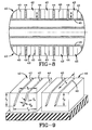
Fig. 8 is a diagrammatic plan view of a test tire tread proving that changes in RAT are achieved with the angled sipes; and -
Fig. 9 is an enlarged perspective view of two of the test tread blocks ofFig. 8 . -
Fig. 1 is a plan view of a portion of a pneumatic tread pattern indicated generally at 1, which includes a pair ofshoulder ribs 2, a pair ofintermediate ribs center rib 5. Eachrib 2 is formed by a plurality oftread blocks 6 separated by generally V-shaped grooves 7. If desiredgrooves 7 could be continuously curved or have multiple angles in addition to the double angle of the V-shape groove as shown. Eachintermediate rib tread blocks 9 separated by laterally extendinggrooves 10.Center rib 5 is formed by a plurality of circumferentially spacedtread blocks 12 separated bylateral grooves 13. Circumferentially extendinggrooves separate rib 3 fromrib 5 andrib 4 fromrib 5 respectively. The particular shapes of the tread blocks shown inFig. 1 can vary without affecting the concept of the invention as well as the various directions and shapes of the intervening grooves. Likewise, the various ribs can have the tread blocks integrally connected to form a continuous rib as opposed to the discontinuous figuration of the ribs as shown inFig. 1 .Ribs mid-circumferential plane 15 of the tread pattern. - In accordance with the invention,
sipes tread blocks 9 and extend at an angle A (Fig. 5 ) with respect to a plane indicated at 20 inFig. 5 , which extends generally perpendicular to the tread block and in a generally radial direction through the axis of rotation of the tire.Sipes 17 intread blocks 9 ofrib 3 are slanted at the same angle, but in an equal and opposite direction with respect toplane 20 to that ofsipes 18 ofrib 4 as shown inFig. 4 .Sipes - In a preferred embodiment,
sipes groove bottom surface 22 or only partially thereto without affecting the concept of the invention so long as the sipes inopposite ribs Fig. 1 , this number can vary so long as substantially the same number of sipes are formed in each tread block. The sipes need not extend perpendicular tomid-circumferential plane 15 as shown inFig. 1 , but can extend at an angle thereto as shown in modifiedtread pattern 24 inFig. 6. Fig. 6 showssipes 25 and 26 formed intread blocks 9 extending at an angle with respect tomid-circumferential plane 15. Again, the same number of sipes will be formed in eachtread block 9, but sloped in opposite directions as shown inFigs. 3 and 4 . -
Fig. 7 shows another modifiedtread pattern 27 in which sipes 28 and 29 have a zig-zag configuration and are symmetrical to each other except that the sipes will be slanted in opposite directions with respect to those in the opposite rib as discussed above. - The tread pattern of
Fig. 6 also shows the formation ofangled sipes shoulder ribs 2, which again are of equal and opposite angles and depths to each other in the respective opposite ribs with respect toplane 15. - Tests have been performed to prove that the angled sipes do affect the residual aligning torque shown diagrammatically in
Figs. 8 and 9 . -
Fig. 8 is a diagrammatic foot print of an actual test tire which proved that a change in RAT can be achieved by providing angled sipes and by varying both the depth and angle of the sipes in the tread blocks. Set forth below is Chart One which was developed by Finite Element Analysis (FEA) in order to mathematically determine what, if any effect the angled sipes would have on the RAT. - In the test tire of
Fig. 8 ,sipes 40, two of which are formed in eachtread block 42, were provided inshoulder ribs 43.Blocks 42 were formed bylateral grooves 44 andcircumferential grooves 45. The various parameters which were considered and which could effect the change in RAT are shown inFig. 9 . These parameters include Pd (radial sipe depth); Pg (sipe gauge or width); Pb (distance of sipe base to leading edge); Pe (distance of sipe opening to leading edge); Px (sipe angle of inclination); and Pw (sipe lateral width).CHART ONE Sipe Angle Compressiv e Force (lbs) Circumferential Direction Thrust/Element (lbs) Net RAT N-m Anticip ated Result On Tire N-m 0 63.25 0.0 0 0.0 5 62.98 1.46 4 1.89 10 62.17 2.88 8 3.69 - Actual tests were then performed on two tires which had the parameters set forth in Chart Two and shown in
Fig. 9 .CHART TWO Sipe Angle (degrees) Measured RAT N-m Net Angled Tie Bar RAT Effect (N-m) -7 -5.52 -1.93 No Sipes -3.59 - 7 -1.77 1.82 - The FEA calculations showed that the projected sensitivity to the sipe inclination angle is about 0.37 N-m/º inclination angle. The actual measured change in RAT obtained from the test results in Chart Two showed a change in RAT of 0.28 N-m /º inclination angle. It is believed that the main reason for the difference between the model affect and the actual affect on the test tires is in the material properties of the tread compound and the loading corrections on the tire. Most importantly, the test results show there is a definite change in RAT by providing angled sipes in the tread blocks and that various changes in RAT can be achieved by varying the sipe angle and that the amount of desired change in RAT can be determined to some degree of certainty by FEA as set forth in Chart One.
- Thus, a tire manufacturer can change the RAT of a tire easily by providing angled sipe blades in the mold and can arrive at a projected amount of change initially through FEA which then can be incorporated into an actual tire for subsequent testing. Thus, FEA avoids the more expensive and time consuming production of samples and actual testing of tires in order to arrive at the desired change of RAT since a change in RAT can be pre-calculated.
- While the embodiments in the invention has been described, the invention is not limited thereto. The claims of the invention follow.
Claims (11)
- A pneumatic tire comprising:a circumferentially extending tread pattern (1; 24; 27) with circumferentially extending ribs (2, 3, 4; 43), said ribs being located on opposite sides of a mid-circumferential plane (15) of said tire;a plurality of tread blocks (6, 9; 42) within at least some of the circumferentially extending ribs (2, 3, 4; 43), said tread blocks (6, 9; 42) being separated by laterally extending grooves (7, 10; 44);an angled sipe (17, 18; 25, 26; 28, 29; 33, 34; 40) formed in at least some of the tread blocks, each sipe extending for a sipe lateral width (W) and a radial sipe depth (D) at a sipe angle of inclination (A) between 2° and 15° with respect to a radial plane (20) passing through an outermost tread surface of the tread block (6, 9; 42) and adjacent to the sipe (17, 18; 25, 26; 28, 29; 33, 34; 40) and through an axis of rotation of the tire,characterized in thateach sipe (17; 25; 28; 33; 40) within circumferentially extending ribs (2, 3, 4; 43) on a first side of the mid-circumferential plane (15) extends at a first sipe angle of inclination (A) with respect to said radial plane (20) for the sipe lateral width (W) and the radial sipe depth (D), and in thateach sipe (18; 26; 29; 34; 40) within circumferentially extending ribs (2, 3, 4; 43) on a second side of the mid-circumferential plane extends at a second sipe angle of inclination (A) with respect to said radial plane (20) that is substantially equal to and opposite the first sipe angle of inclination (A) for the sipe lateral width (W) and the radial sipe depth (D),wherein said tread blocks (6, 9; 42) on opposite sides of the mid-circumferential plane create a force on the tire during load bearing rotation of the tire against a surface, said force including forces that extend in opposite directions on opposite sides of the mid-circumferential plane (15) creating an overall moment on the tire to affect tire residual aligning torque.
- The tire defined in claim 1 wherein the sipe angle of inclination (A) is 7°.
- The tire defined in claim 1 or claim 2 wherein the sipes (17, 18; 25, 26; 28, 29; 33, 34; 40) have a depth of between 20% and 100% of the height of the tread blocks (6, 9; 42).
- The tire defined in any one of claims 1-3 wherein the sipes (17, 18; 40) are substantially perpendicular to the mid-circumferencial plane (15) of the tire.
- The tire defined in any one of claims 1-3 wherein the sipes (25, 26) are formed at an angle with respect to the mid-circumferential plane (15) of the tire.
- The tire defined in any one of claims 1-5 wherein the sipes (17, 18; 25, 26; 28, 29; 33, 34; 40) each have a width of between 0.038mm to 1.52mm (0.015 inches and 0.06 inches).
- The tire defined in any one of claims 1-3 or 6 wherein the sipes (33, 34; 40) are formed in opposed shoulder ribs (2; 43) of the tire.
- The tire defined in any one of claims 1-6 wherein the sipes (17, 18; 25, 26; 28, 29) are formed in opposed intermediate ribs (3, 4) of the tire.
- The tire defined in any one of claims 1-3, 5, 6 or 8 wherein the sipes (25, 26) extend partially across the lateral width of the tread blocks (3, 4).
- The tire defined in any one of claims 1-9 wherein a plurality of the sipes (17, 18; 25, 26; 28, 29; 33, 34; 40) are formed in each of the tread blocks (6, 9; 42).
- A method of manufacturing a pneumatic tire, the method comprising:selecting an existing tire tread mold with a tread pattern that includes:a circumferentially extending tread pattern (1; 24; 27) with circumferentially extending ribs (2, 3, 4; 43), said ribs being located on opposite sides of a mid-circumferential plane (15) of said tire; anda plurality of tread blocks (6, 9; 42) within at least some of the circumferentially extending ribs (2, 3, 4; 43), said tread blocks (6, 9; 42) being separated by laterally extending grooves (7, 10; 44);building a finite element model of the pneumatic tire with the tread pattern that corresponds to the selected mold, wherein the modeled pneumatic tire includes:an angled sipe (17, 18; 25, 26; 28, 29; 33, 34; 40) formed in at least some of the tread blocks, each angled sipe (17, 18; 25, 26; 28, 29; 33, 34; 40) extending for a sipe lateral width (W) and a radial sipe depth (D) at a sipe angle of inclination (A) between 2° and 15° with respect to a radial plane (20) passing through an outermost tread surface of the tread block (6, 9; 42) and adjacent to the angled sipe (17, 18; 25, 26; 28, 29; 33, 34; 40) and through an axis of rotation of the modeled tire,wherein each angled sipes (17; 25; 28; 33; 40) within circumferentially extending ribs (2, 3, 4; 43) on a first side of the mid-circumferential plane (15) extend at a first sipe angle of inclination (A) with respect to said radial plane (20) for the sipe lateral width (W) and the radial sipe depth (D), andwherein each angled sipes (18; 26; 29; 34; 40) within circumferentially extending ribs (2, 3, 4; 43) on a second side of the mid-circumferential plane (15) extend at a second sipe angle of inclination (A) with respect to said radial plane (20) that is substantially equal to and opposite the first sipe angle of inclination (A) for the sipe lateral width (W) and the radial sipe depth (D),performing a plurality of computer simulations based upon the finite element model wherein said first sipe angle of inclination (A) and said second sipe angle of inclination (A) are varied until a simulated tire with a desired residual aligning torque is achieved;inserting angled sipe blades into the selected tire tread mold that correspond to a first sipe angle of inclination (A) and a second sipe angle of inclination (A) determined based upon the simulation to result in the desired residual aligning torque; andcasting a tread upon the pneumatic tire using the selected mold and the inserted angled sipe blades, thereby producing the pneumatic tire with a desired residual aligning torque without permanently altering the mold from which the tire tread is formed.
Applications Claiming Priority (3)
| Application Number | Priority Date | Filing Date | Title |
|---|---|---|---|
| US09/922,964 US7090735B2 (en) | 2001-08-06 | 2001-08-06 | Method of compensating for residual aligning torque (RAT) |
| US922964 | 2001-08-06 | ||
| PCT/US2002/022572 WO2003013882A1 (en) | 2001-08-06 | 2002-07-17 | Method of compensating for residual aligning torque (rat) |
Publications (2)
| Publication Number | Publication Date |
|---|---|
| EP1414654A1 EP1414654A1 (en) | 2004-05-06 |
| EP1414654B1 true EP1414654B1 (en) | 2012-08-15 |
Family
ID=25447882
Family Applications (1)
| Application Number | Title | Priority Date | Filing Date |
|---|---|---|---|
| EP02763287A Expired - Lifetime EP1414654B1 (en) | 2001-08-06 | 2002-07-17 | Pneumatic tire compensating for residual aligning torque (rat) and its manufacturing method |
Country Status (6)
| Country | Link |
|---|---|
| US (1) | US7090735B2 (en) |
| EP (1) | EP1414654B1 (en) |
| JP (1) | JP4573529B2 (en) |
| BR (1) | BR0211767B1 (en) |
| CA (1) | CA2456309C (en) |
| WO (1) | WO2003013882A1 (en) |
Families Citing this family (14)
| Publication number | Priority date | Publication date | Assignee | Title |
|---|---|---|---|---|
| EP1510368B1 (en) * | 1999-01-13 | 2014-06-18 | Bridgestone Corporation | Pneumatic tire having excellent steering stability |
| KR100502555B1 (en) * | 2003-07-09 | 2005-07-21 | 한국타이어 주식회사 | Method for controlling PRAT as tire properties |
| JP4628055B2 (en) * | 2004-09-30 | 2011-02-09 | 株式会社ブリヂストン | Pneumatic tire |
| US8916001B2 (en) * | 2006-04-05 | 2014-12-23 | Gvd Corporation | Coated molds and related methods and components |
| US8056202B2 (en) | 2006-04-27 | 2011-11-15 | Bridgestone Americas Tire Operations, Llc | Tire replacement system for compact tractor |
| FR2928866B1 (en) * | 2008-03-20 | 2010-03-19 | Michelin Soc Tech | SCULPTURE FOR TIRE TREAD |
| WO2009137056A2 (en) * | 2008-05-07 | 2009-11-12 | Bridgestone Americas Tire Operations, Llc | Method of designing a tire having a target residual aligning torque |
| US9616716B2 (en) | 2011-12-14 | 2017-04-11 | Bridgestone Americas Tire Operations, Llc | Three dimensional sipe |
| DE102011056762A1 (en) * | 2011-12-21 | 2013-06-27 | Continental Reifen Deutschland Gmbh | Arrangement of pneumatic vehicle tires on a vehicle |
| BR112015004749A2 (en) * | 2012-12-28 | 2017-07-04 | Michelin & Cie | adjustment within plysteer parameters mold |
| EP3083283B1 (en) | 2013-12-19 | 2020-01-15 | Bridgestone Americas Tire Operations, LLC | Tire having circumferentially biased sipe depths |
| CN112996672B (en) * | 2018-11-16 | 2022-12-23 | 米其林集团总公司 | Heavy duty truck tires having a shoulder rib sipe arrangement |
| EP4015203B1 (en) | 2020-12-18 | 2023-10-11 | The Goodyear Tire & Rubber Company | Tire mold |
| US11807045B2 (en) | 2021-06-14 | 2023-11-07 | The Goodyear Tire & Rubber Company | Tire with hybrid sipe pattern |
Family Cites Families (44)
| Publication number | Priority date | Publication date | Assignee | Title |
|---|---|---|---|---|
| US2339558A (en) | 1942-03-21 | 1944-01-18 | Firestone Tire & Rubber Co | Tire |
| FR2461602A1 (en) * | 1979-07-24 | 1981-02-06 | Michelin & Cie | PNEUMATIC FOR ROLLING ON SNOW |
| JPS57104404A (en) * | 1980-12-19 | 1982-06-29 | Yokohama Rubber Co Ltd:The | Radial tire |
| JPS57130802A (en) | 1981-02-03 | 1982-08-13 | Bridgestone Corp | Two main grooved rib type tread pattern with subsidiary grooves of superior resistance to gravel catching and gravel removing function |
| US4449560A (en) | 1981-05-13 | 1984-05-22 | Bridgestone Tire Company Limited | Heavy duty pneumatic tire |
| CA1198043A (en) | 1981-06-12 | 1985-12-17 | Barry W. Treves | Tyre treads |
| FR2544251B1 (en) | 1983-04-12 | 1986-05-09 | Michelin & Cie | RELIEF ELEMENTS OF A TIRE TREAD COMPRISING WAVY OR BROKEN TRACK INCISIONS |
| DE3324649A1 (en) | 1983-07-08 | 1985-01-31 | Continental Gummi-Werke Ag, 3000 Hannover | VEHICLE TIRES |
| JPS6397405A (en) * | 1986-10-14 | 1988-04-28 | Yukio Murashima | Tire tread pattern |
| US5131444A (en) | 1987-10-20 | 1992-07-21 | Bridgestone Corporation | Heavy duty pneumatic tires including stepped tread zones for preventing uneven wearing |
| JPH0253608A (en) * | 1988-08-12 | 1990-02-22 | Sumitomo Rubber Ind Ltd | Pneumatic radial tire |
| US4936363A (en) | 1988-08-15 | 1990-06-26 | The Goodyear Tire & Rubber Company | Tread for a pneumatic tire with circumferential slot to prevent the spread of river wear |
| JPH068081B2 (en) | 1989-11-10 | 1994-02-02 | 株式会社ブリヂストン | Pneumatic tire |
| AT398732B (en) * | 1990-03-20 | 1995-01-25 | Semperit Ag | VEHICLE TIRES |
| JP2994008B2 (en) * | 1990-08-16 | 1999-12-27 | 株式会社ブリヂストン | Pneumatic radial tire |
| JP2643058B2 (en) | 1991-08-26 | 1997-08-20 | 住友ゴム工業株式会社 | Pneumatic radial tire |
| DE4139344A1 (en) | 1991-11-29 | 1993-06-03 | Bosch Gmbh Robert | HAND MILLING |
| JPH05319029A (en) | 1992-05-27 | 1993-12-03 | Yokohama Rubber Co Ltd:The | Pneumatic radial tire for heavy load |
| JP2702873B2 (en) * | 1992-09-16 | 1998-01-26 | 住友ゴム工業株式会社 | Radial tire |
| DE69304021T2 (en) * | 1992-11-20 | 1996-12-19 | Sumitomo Rubber Ind | Method for selecting a tread pattern that prevents the vehicle from skewing |
| ES2089690T3 (en) | 1992-12-30 | 1996-10-01 | Michelin Rech Tech | TIRE ROLLER BELT COMPENSATING FOR THE RESIDUAL ALIGNMENT TORQUE. |
| US5960845A (en) * | 1993-07-23 | 1999-10-05 | Sumitomo Rubber Industries, Ltd. | Pneumatic tire |
| FI944892L (en) | 1993-11-18 | 1995-08-18 | Bridgestone Corp | Pneumatic tire |
| JP2763066B2 (en) * | 1993-12-29 | 1998-06-11 | 住友ゴム工業株式会社 | Pneumatic tire |
| IT1276320B1 (en) | 1994-02-22 | 1997-10-28 | Pirelli | TIRE FOR MEDIUM / HEAVY TRANSPORT VEHICLES WITH UNIVERSAL TYPE TREAD |
| JP3366737B2 (en) | 1994-06-29 | 2003-01-14 | 株式会社ブリヂストン | Pneumatic tire |
| US5538060A (en) * | 1994-12-27 | 1996-07-23 | The Goodyear Tire & Rubber Company | Pneumatic tire having tread portion including blocks |
| DE19506697A1 (en) * | 1995-02-25 | 1996-08-29 | Continental Ag | Forming fine cuts in tyre tread esp. for winter use in snow and ice |
| US5669993A (en) * | 1995-06-29 | 1997-09-23 | The Goodyear Tire & Rubber Company | Tire tread elements with built-in twist |
| EP0761479A3 (en) | 1995-07-24 | 1997-06-04 | Goodyear Tire & Rubber | Aligning torque generation via inclined lateral tread grooves |
| JP3079026B2 (en) * | 1995-11-15 | 2000-08-21 | 住友ゴム工業株式会社 | studless tire |
| US5733393A (en) | 1996-01-17 | 1998-03-31 | The Goodyear Tire & Rubber Company | Tire having good diverse properties |
| EP0810104A1 (en) * | 1996-05-28 | 1997-12-03 | The Goodyear Tire & Rubber Company | Treads for tires with siped elastomeric blocks |
| EP0816130B1 (en) | 1996-06-28 | 2005-02-09 | Sumitomo Rubber Industries Limited | Pneumatic tyre |
| JP3636253B2 (en) | 1996-09-11 | 2005-04-06 | 株式会社ブリヂストン | Mold for vulcanizing pneumatic tires |
| JP3626300B2 (en) * | 1996-11-08 | 2005-03-02 | 住友ゴム工業株式会社 | Pneumatic tire |
| WO1998029270A1 (en) * | 1996-12-27 | 1998-07-09 | Bridgestone Corporation | Pneumatic tire designing method |
| ES2234037T3 (en) * | 1996-12-27 | 2005-06-16 | Bridgestone Corporation | PROCEDURE FOR THE DESIGN OF A TIRE. |
| JP4390879B2 (en) * | 1997-12-24 | 2009-12-24 | 株式会社ブリヂストン | Pneumatic tire |
| US6786257B1 (en) * | 1998-11-20 | 2004-09-07 | Bridgestone Corporation | Pneumatic tire including twisted sipe |
| JP2000255226A (en) * | 1998-12-22 | 2000-09-19 | Pirelli Pneumatici Spa | Method for determining a preselected performance characteristic of a tire tread and a tire provided with a tread having optimum characteristics with respect to said performance characteristic |
| ES2199515T3 (en) | 1998-12-23 | 2004-02-16 | Pirelli Pneumatici S.P.A. | TIRES FOR VEHICLE WHEELS. |
| JP2001219715A (en) * | 1999-01-13 | 2001-08-14 | Bridgestone Corp | Pneumatic tire with high maneuver stability |
| EP1510368B1 (en) * | 1999-01-13 | 2014-06-18 | Bridgestone Corporation | Pneumatic tire having excellent steering stability |
-
2001
- 2001-08-06 US US09/922,964 patent/US7090735B2/en not_active Expired - Lifetime
-
2002
- 2002-07-17 EP EP02763287A patent/EP1414654B1/en not_active Expired - Lifetime
- 2002-07-17 JP JP2003518850A patent/JP4573529B2/en not_active Expired - Fee Related
- 2002-07-17 WO PCT/US2002/022572 patent/WO2003013882A1/en not_active Ceased
- 2002-07-17 BR BRPI0211767-3A patent/BR0211767B1/en not_active IP Right Cessation
- 2002-07-17 CA CA2456309A patent/CA2456309C/en not_active Expired - Fee Related
Also Published As
| Publication number | Publication date |
|---|---|
| US7090735B2 (en) | 2006-08-15 |
| JP4573529B2 (en) | 2010-11-04 |
| EP1414654A1 (en) | 2004-05-06 |
| CA2456309A1 (en) | 2003-02-20 |
| BR0211767B1 (en) | 2011-06-28 |
| BR0211767A (en) | 2004-07-27 |
| JP2004537454A (en) | 2004-12-16 |
| WO2003013882A1 (en) | 2003-02-20 |
| CA2456309C (en) | 2010-11-30 |
| US20030029535A1 (en) | 2003-02-13 |
Similar Documents
| Publication | Publication Date | Title |
|---|---|---|
| US6488064B1 (en) | Sacrificial ribs for improved tire wear | |
| EP0422902B1 (en) | Pneumatic radial tires | |
| US7017634B2 (en) | Tire tread including hollowed zones | |
| EP0313361B1 (en) | Heavy duty pneumatic tires preventing uneven wearing | |
| US4798236A (en) | High performance tire tread | |
| EP0342908B1 (en) | Pneumatic tyre | |
| US7090735B2 (en) | Method of compensating for residual aligning torque (RAT) | |
| EP0605849B1 (en) | Tire tread to compensate residual aligning torque | |
| JPH10151915A (en) | Pneumatic tire | |
| JP2890310B2 (en) | Pneumatic radial tire | |
| NZ245109A (en) | Radial pneumatic tyre: tread of blocks divided by symmetric branched incisions | |
| JPS61261109A (en) | Pneumatic tire excellent in traction and brake performance | |
| EP1029714B1 (en) | Vehicle tyre | |
| JP2000255226A (en) | Method for determining a preselected performance characteristic of a tire tread and a tire provided with a tread having optimum characteristics with respect to said performance characteristic | |
| JPH0443005B2 (en) | ||
| JPS6343223B2 (en) | ||
| JPS6218305A (en) | Manufacture or tire | |
| AU2007254657B2 (en) | Method of compensating for residual aligning torque (RAT) | |
| JPS6060010A (en) | Pneumatic tire | |
| JP2807649B2 (en) | Pneumatic tire | |
| JP3581203B2 (en) | Heavy duty pneumatic tires | |
| AU2002327252B2 (en) | Method of compensating for residual aligning torque (RAT) | |
| JPH0443006B2 (en) | ||
| AU2002327252A1 (en) | Method of compensating for residual aligning torque (RAT) | |
| JP3938618B2 (en) | Pneumatic tire |
Legal Events
| Date | Code | Title | Description |
|---|---|---|---|
| PUAI | Public reference made under article 153(3) epc to a published international application that has entered the european phase |
Free format text: ORIGINAL CODE: 0009012 |
|
| 17P | Request for examination filed |
Effective date: 20040203 |
|
| AK | Designated contracting states |
Kind code of ref document: A1 Designated state(s): AT BE BG CH CY CZ DE DK EE ES FI FR GB GR IE IT LI LU MC NL PT SE SK TR |
|
| AX | Request for extension of the european patent |
Extension state: AL LT LV MK RO SI |
|
| RIN1 | Information on inventor provided before grant (corrected) |
Inventor name: TURNER, JOHN, L. Inventor name: VOSSBERG, STEVEN Inventor name: NEUGEBAUER, PAUL, M. |
|
| 17Q | First examination report despatched |
Effective date: 20050510 |
|
| 17Q | First examination report despatched |
Effective date: 20050510 |
|
| RAP1 | Party data changed (applicant data changed or rights of an application transferred) |
Owner name: BRIDGESTONE AMERICAS TIRE OPERATIONS, LLC |
|
| RTI1 | Title (correction) |
Free format text: PNEUMATIC TIRE COMPENSATING FOR RESIDUAL ALIGNING TORQUE (RAT) AND ITS MANUFACTURING METHOD |
|
| GRAP | Despatch of communication of intention to grant a patent |
Free format text: ORIGINAL CODE: EPIDOSNIGR1 |
|
| GRAC | Information related to communication of intention to grant a patent modified |
Free format text: ORIGINAL CODE: EPIDOSCIGR1 |
|
| RIC1 | Information provided on ipc code assigned before grant |
Ipc: B60C 11/11 20060101ALI20120216BHEP Ipc: B60C 11/12 20060101AFI20120216BHEP |
|
| GRAS | Grant fee paid |
Free format text: ORIGINAL CODE: EPIDOSNIGR3 |
|
| GRAA | (expected) grant |
Free format text: ORIGINAL CODE: 0009210 |
|
| AK | Designated contracting states |
Kind code of ref document: B1 Designated state(s): DE FR IT |
|
| REG | Reference to a national code |
Ref country code: DE Ref legal event code: R096 Ref document number: 60243530 Country of ref document: DE Effective date: 20121011 |
|
| PLBE | No opposition filed within time limit |
Free format text: ORIGINAL CODE: 0009261 |
|
| STAA | Information on the status of an ep patent application or granted ep patent |
Free format text: STATUS: NO OPPOSITION FILED WITHIN TIME LIMIT |
|
| 26N | No opposition filed |
Effective date: 20130516 |
|
| REG | Reference to a national code |
Ref country code: DE Ref legal event code: R097 Ref document number: 60243530 Country of ref document: DE Effective date: 20130516 |
|
| REG | Reference to a national code |
Ref country code: FR Ref legal event code: PLFP Year of fee payment: 15 |
|
| PGFP | Annual fee paid to national office [announced via postgrant information from national office to epo] |
Ref country code: FR Payment date: 20160621 Year of fee payment: 15 |
|
| PGFP | Annual fee paid to national office [announced via postgrant information from national office to epo] |
Ref country code: DE Payment date: 20160801 Year of fee payment: 15 Ref country code: IT Payment date: 20160722 Year of fee payment: 15 |
|
| REG | Reference to a national code |
Ref country code: DE Ref legal event code: R119 Ref document number: 60243530 Country of ref document: DE |
|
| REG | Reference to a national code |
Ref country code: FR Ref legal event code: ST Effective date: 20180330 |
|
| PG25 | Lapsed in a contracting state [announced via postgrant information from national office to epo] |
Ref country code: DE Free format text: LAPSE BECAUSE OF NON-PAYMENT OF DUE FEES Effective date: 20180201 |
|
| PG25 | Lapsed in a contracting state [announced via postgrant information from national office to epo] |
Ref country code: FR Free format text: LAPSE BECAUSE OF NON-PAYMENT OF DUE FEES Effective date: 20170731 |
|
| PG25 | Lapsed in a contracting state [announced via postgrant information from national office to epo] |
Ref country code: IT Free format text: LAPSE BECAUSE OF NON-PAYMENT OF DUE FEES Effective date: 20170717 |