EP1414634B1 - Process and apparatus for injection moulding - Google Patents
Process and apparatus for injection moulding Download PDFInfo
- Publication number
- EP1414634B1 EP1414634B1 EP02751307A EP02751307A EP1414634B1 EP 1414634 B1 EP1414634 B1 EP 1414634B1 EP 02751307 A EP02751307 A EP 02751307A EP 02751307 A EP02751307 A EP 02751307A EP 1414634 B1 EP1414634 B1 EP 1414634B1
- Authority
- EP
- European Patent Office
- Prior art keywords
- plastics material
- mould cavity
- plastics
- cavity
- mould
- Prior art date
- Legal status (The legal status is an assumption and is not a legal conclusion. Google has not performed a legal analysis and makes no representation as to the accuracy of the status listed.)
- Expired - Lifetime
Links
- 238000000034 method Methods 0.000 title claims abstract description 102
- 238000001746 injection moulding Methods 0.000 title claims abstract description 94
- 230000008569 process Effects 0.000 title claims abstract description 92
- 239000004033 plastic Substances 0.000 claims abstract description 515
- 229920003023 plastic Polymers 0.000 claims abstract description 515
- 239000000463 material Substances 0.000 claims abstract description 322
- 239000007788 liquid Substances 0.000 claims abstract description 79
- 238000002347 injection Methods 0.000 claims abstract description 69
- 239000007924 injection Substances 0.000 claims abstract description 69
- 238000012856 packing Methods 0.000 claims abstract description 61
- 238000000465 moulding Methods 0.000 claims description 44
- 230000007246 mechanism Effects 0.000 claims description 12
- 239000012530 fluid Substances 0.000 claims description 6
- 230000005540 biological transmission Effects 0.000 claims description 4
- 238000009966 trimming Methods 0.000 claims description 4
- 230000008878 coupling Effects 0.000 claims description 2
- 238000010168 coupling process Methods 0.000 claims description 2
- 238000005859 coupling reaction Methods 0.000 claims description 2
- 239000007789 gas Substances 0.000 description 171
- 239000000047 product Substances 0.000 description 12
- 238000004519 manufacturing process Methods 0.000 description 8
- 239000011347 resin Substances 0.000 description 7
- 229920005989 resin Polymers 0.000 description 7
- IJGRMHOSHXDMSA-UHFFFAOYSA-N Atomic nitrogen Chemical compound N#N IJGRMHOSHXDMSA-UHFFFAOYSA-N 0.000 description 6
- 230000001276 controlling effect Effects 0.000 description 6
- 238000001816 cooling Methods 0.000 description 6
- 230000010076 replication Effects 0.000 description 6
- 230000008602 contraction Effects 0.000 description 5
- 230000001419 dependent effect Effects 0.000 description 5
- 230000008901 benefit Effects 0.000 description 4
- 238000007711 solidification Methods 0.000 description 4
- 230000008023 solidification Effects 0.000 description 4
- 229920001169 thermoplastic Polymers 0.000 description 4
- 239000004416 thermosoftening plastic Substances 0.000 description 4
- 239000002991 molded plastic Substances 0.000 description 3
- 229910052757 nitrogen Inorganic materials 0.000 description 3
- 239000007787 solid Substances 0.000 description 3
- 230000015572 biosynthetic process Effects 0.000 description 2
- 238000006073 displacement reaction Methods 0.000 description 2
- 239000011521 glass Substances 0.000 description 2
- 238000003754 machining Methods 0.000 description 2
- 239000002184 metal Substances 0.000 description 2
- 239000012768 molten material Substances 0.000 description 2
- 230000035515 penetration Effects 0.000 description 2
- 230000001105 regulatory effect Effects 0.000 description 2
- 230000000717 retained effect Effects 0.000 description 2
- 238000013022 venting Methods 0.000 description 2
- XLYOFNOQVPJJNP-UHFFFAOYSA-N water Substances O XLYOFNOQVPJJNP-UHFFFAOYSA-N 0.000 description 2
- 230000035508 accumulation Effects 0.000 description 1
- 238000009825 accumulation Methods 0.000 description 1
- 230000009286 beneficial effect Effects 0.000 description 1
- 238000004891 communication Methods 0.000 description 1
- 230000005574 cross-species transmission Effects 0.000 description 1
- 238000013461 design Methods 0.000 description 1
- 239000000835 fiber Substances 0.000 description 1
- 229910052500 inorganic mineral Inorganic materials 0.000 description 1
- 239000011344 liquid material Substances 0.000 description 1
- 239000011707 mineral Substances 0.000 description 1
- 230000002093 peripheral effect Effects 0.000 description 1
- 239000012466 permeate Substances 0.000 description 1
- 239000013641 positive control Substances 0.000 description 1
- 238000002360 preparation method Methods 0.000 description 1
- 230000002035 prolonged effect Effects 0.000 description 1
- 238000011084 recovery Methods 0.000 description 1
- 238000012360 testing method Methods 0.000 description 1
- 238000011144 upstream manufacturing Methods 0.000 description 1
- 239000002699 waste material Substances 0.000 description 1
Images





Classifications
-
- B—PERFORMING OPERATIONS; TRANSPORTING
- B29—WORKING OF PLASTICS; WORKING OF SUBSTANCES IN A PLASTIC STATE IN GENERAL
- B29C—SHAPING OR JOINING OF PLASTICS; SHAPING OF MATERIAL IN A PLASTIC STATE, NOT OTHERWISE PROVIDED FOR; AFTER-TREATMENT OF THE SHAPED PRODUCTS, e.g. REPAIRING
- B29C45/00—Injection moulding, i.e. forcing the required volume of moulding material through a nozzle into a closed mould; Apparatus therefor
- B29C45/17—Component parts, details or accessories; Auxiliary operations
- B29C45/1703—Introducing an auxiliary fluid into the mould
- B29C45/1704—Introducing an auxiliary fluid into the mould the fluid being introduced into the interior of the injected material which is still in a molten state, e.g. for producing hollow articles
- B29C45/1711—Introducing an auxiliary fluid into the mould the fluid being introduced into the interior of the injected material which is still in a molten state, e.g. for producing hollow articles and removing excess material from the mould cavity by the introduced fluid, e.g. to an overflow cavity
-
- B—PERFORMING OPERATIONS; TRANSPORTING
- B29—WORKING OF PLASTICS; WORKING OF SUBSTANCES IN A PLASTIC STATE IN GENERAL
- B29C—SHAPING OR JOINING OF PLASTICS; SHAPING OF MATERIAL IN A PLASTIC STATE, NOT OTHERWISE PROVIDED FOR; AFTER-TREATMENT OF THE SHAPED PRODUCTS, e.g. REPAIRING
- B29C45/00—Injection moulding, i.e. forcing the required volume of moulding material through a nozzle into a closed mould; Apparatus therefor
- B29C45/17—Component parts, details or accessories; Auxiliary operations
-
- B—PERFORMING OPERATIONS; TRANSPORTING
- B29—WORKING OF PLASTICS; WORKING OF SUBSTANCES IN A PLASTIC STATE IN GENERAL
- B29C—SHAPING OR JOINING OF PLASTICS; SHAPING OF MATERIAL IN A PLASTIC STATE, NOT OTHERWISE PROVIDED FOR; AFTER-TREATMENT OF THE SHAPED PRODUCTS, e.g. REPAIRING
- B29C45/00—Injection moulding, i.e. forcing the required volume of moulding material through a nozzle into a closed mould; Apparatus therefor
- B29C45/17—Component parts, details or accessories; Auxiliary operations
- B29C45/1703—Introducing an auxiliary fluid into the mould
- B29C45/1732—Control circuits therefor
-
- B—PERFORMING OPERATIONS; TRANSPORTING
- B29—WORKING OF PLASTICS; WORKING OF SUBSTANCES IN A PLASTIC STATE IN GENERAL
- B29C—SHAPING OR JOINING OF PLASTICS; SHAPING OF MATERIAL IN A PLASTIC STATE, NOT OTHERWISE PROVIDED FOR; AFTER-TREATMENT OF THE SHAPED PRODUCTS, e.g. REPAIRING
- B29C45/00—Injection moulding, i.e. forcing the required volume of moulding material through a nozzle into a closed mould; Apparatus therefor
- B29C45/17—Component parts, details or accessories; Auxiliary operations
- B29C45/76—Measuring, controlling or regulating
- B29C45/762—Measuring, controlling or regulating the sequence of operations of an injection cycle
-
- B—PERFORMING OPERATIONS; TRANSPORTING
- B29—WORKING OF PLASTICS; WORKING OF SUBSTANCES IN A PLASTIC STATE IN GENERAL
- B29C—SHAPING OR JOINING OF PLASTICS; SHAPING OF MATERIAL IN A PLASTIC STATE, NOT OTHERWISE PROVIDED FOR; AFTER-TREATMENT OF THE SHAPED PRODUCTS, e.g. REPAIRING
- B29C45/00—Injection moulding, i.e. forcing the required volume of moulding material through a nozzle into a closed mould; Apparatus therefor
- B29C45/17—Component parts, details or accessories; Auxiliary operations
- B29C45/1703—Introducing an auxiliary fluid into the mould
- B29C45/1704—Introducing an auxiliary fluid into the mould the fluid being introduced into the interior of the injected material which is still in a molten state, e.g. for producing hollow articles
- B29C45/1711—Introducing an auxiliary fluid into the mould the fluid being introduced into the interior of the injected material which is still in a molten state, e.g. for producing hollow articles and removing excess material from the mould cavity by the introduced fluid, e.g. to an overflow cavity
- B29C2045/1712—Introducing an auxiliary fluid into the mould the fluid being introduced into the interior of the injected material which is still in a molten state, e.g. for producing hollow articles and removing excess material from the mould cavity by the introduced fluid, e.g. to an overflow cavity plastic material flowing back into the injection unit
-
- B—PERFORMING OPERATIONS; TRANSPORTING
- B29—WORKING OF PLASTICS; WORKING OF SUBSTANCES IN A PLASTIC STATE IN GENERAL
- B29C—SHAPING OR JOINING OF PLASTICS; SHAPING OF MATERIAL IN A PLASTIC STATE, NOT OTHERWISE PROVIDED FOR; AFTER-TREATMENT OF THE SHAPED PRODUCTS, e.g. REPAIRING
- B29C45/00—Injection moulding, i.e. forcing the required volume of moulding material through a nozzle into a closed mould; Apparatus therefor
- B29C45/17—Component parts, details or accessories; Auxiliary operations
- B29C45/1703—Introducing an auxiliary fluid into the mould
- B29C45/1704—Introducing an auxiliary fluid into the mould the fluid being introduced into the interior of the injected material which is still in a molten state, e.g. for producing hollow articles
- B29C45/1711—Introducing an auxiliary fluid into the mould the fluid being introduced into the interior of the injected material which is still in a molten state, e.g. for producing hollow articles and removing excess material from the mould cavity by the introduced fluid, e.g. to an overflow cavity
- B29C2045/1713—Introducing an auxiliary fluid into the mould the fluid being introduced into the interior of the injected material which is still in a molten state, e.g. for producing hollow articles and removing excess material from the mould cavity by the introduced fluid, e.g. to an overflow cavity using several overflow cavities
-
- B—PERFORMING OPERATIONS; TRANSPORTING
- B29—WORKING OF PLASTICS; WORKING OF SUBSTANCES IN A PLASTIC STATE IN GENERAL
- B29C—SHAPING OR JOINING OF PLASTICS; SHAPING OF MATERIAL IN A PLASTIC STATE, NOT OTHERWISE PROVIDED FOR; AFTER-TREATMENT OF THE SHAPED PRODUCTS, e.g. REPAIRING
- B29C45/00—Injection moulding, i.e. forcing the required volume of moulding material through a nozzle into a closed mould; Apparatus therefor
- B29C45/17—Component parts, details or accessories; Auxiliary operations
- B29C45/1703—Introducing an auxiliary fluid into the mould
- B29C45/1704—Introducing an auxiliary fluid into the mould the fluid being introduced into the interior of the injected material which is still in a molten state, e.g. for producing hollow articles
- B29C2045/1719—Introducing an auxiliary fluid into the mould the fluid being introduced into the interior of the injected material which is still in a molten state, e.g. for producing hollow articles making tubular articles
-
- B—PERFORMING OPERATIONS; TRANSPORTING
- B29—WORKING OF PLASTICS; WORKING OF SUBSTANCES IN A PLASTIC STATE IN GENERAL
- B29C—SHAPING OR JOINING OF PLASTICS; SHAPING OF MATERIAL IN A PLASTIC STATE, NOT OTHERWISE PROVIDED FOR; AFTER-TREATMENT OF THE SHAPED PRODUCTS, e.g. REPAIRING
- B29C45/00—Injection moulding, i.e. forcing the required volume of moulding material through a nozzle into a closed mould; Apparatus therefor
- B29C45/17—Component parts, details or accessories; Auxiliary operations
- B29C45/1703—Introducing an auxiliary fluid into the mould
- B29C45/1704—Introducing an auxiliary fluid into the mould the fluid being introduced into the interior of the injected material which is still in a molten state, e.g. for producing hollow articles
- B29C2045/173—Introducing an auxiliary fluid into the mould the fluid being introduced into the interior of the injected material which is still in a molten state, e.g. for producing hollow articles using a plurality of fluid injection nozzles
-
- B—PERFORMING OPERATIONS; TRANSPORTING
- B29—WORKING OF PLASTICS; WORKING OF SUBSTANCES IN A PLASTIC STATE IN GENERAL
- B29C—SHAPING OR JOINING OF PLASTICS; SHAPING OF MATERIAL IN A PLASTIC STATE, NOT OTHERWISE PROVIDED FOR; AFTER-TREATMENT OF THE SHAPED PRODUCTS, e.g. REPAIRING
- B29C45/00—Injection moulding, i.e. forcing the required volume of moulding material through a nozzle into a closed mould; Apparatus therefor
- B29C45/17—Component parts, details or accessories; Auxiliary operations
- B29C45/46—Means for plasticising or homogenising the moulding material or forcing it into the mould
- B29C2045/468—Means for plasticising or homogenising the moulding material or forcing it into the mould using a fluid as directly acting injection means
-
- B—PERFORMING OPERATIONS; TRANSPORTING
- B29—WORKING OF PLASTICS; WORKING OF SUBSTANCES IN A PLASTIC STATE IN GENERAL
- B29C—SHAPING OR JOINING OF PLASTICS; SHAPING OF MATERIAL IN A PLASTIC STATE, NOT OTHERWISE PROVIDED FOR; AFTER-TREATMENT OF THE SHAPED PRODUCTS, e.g. REPAIRING
- B29C2945/00—Indexing scheme relating to injection moulding, i.e. forcing the required volume of moulding material through a nozzle into a closed mould
- B29C2945/76—Measuring, controlling or regulating
- B29C2945/76494—Controlled parameter
- B29C2945/76498—Pressure
-
- B—PERFORMING OPERATIONS; TRANSPORTING
- B29—WORKING OF PLASTICS; WORKING OF SUBSTANCES IN A PLASTIC STATE IN GENERAL
- B29C—SHAPING OR JOINING OF PLASTICS; SHAPING OF MATERIAL IN A PLASTIC STATE, NOT OTHERWISE PROVIDED FOR; AFTER-TREATMENT OF THE SHAPED PRODUCTS, e.g. REPAIRING
- B29C2945/00—Indexing scheme relating to injection moulding, i.e. forcing the required volume of moulding material through a nozzle into a closed mould
- B29C2945/76—Measuring, controlling or regulating
- B29C2945/76494—Controlled parameter
- B29C2945/76568—Position
- B29C2945/76575—Position end position
-
- B—PERFORMING OPERATIONS; TRANSPORTING
- B29—WORKING OF PLASTICS; WORKING OF SUBSTANCES IN A PLASTIC STATE IN GENERAL
- B29C—SHAPING OR JOINING OF PLASTICS; SHAPING OF MATERIAL IN A PLASTIC STATE, NOT OTHERWISE PROVIDED FOR; AFTER-TREATMENT OF THE SHAPED PRODUCTS, e.g. REPAIRING
- B29C2945/00—Indexing scheme relating to injection moulding, i.e. forcing the required volume of moulding material through a nozzle into a closed mould
- B29C2945/76—Measuring, controlling or regulating
- B29C2945/76494—Controlled parameter
- B29C2945/76595—Velocity
-
- B—PERFORMING OPERATIONS; TRANSPORTING
- B29—WORKING OF PLASTICS; WORKING OF SUBSTANCES IN A PLASTIC STATE IN GENERAL
- B29C—SHAPING OR JOINING OF PLASTICS; SHAPING OF MATERIAL IN A PLASTIC STATE, NOT OTHERWISE PROVIDED FOR; AFTER-TREATMENT OF THE SHAPED PRODUCTS, e.g. REPAIRING
- B29C2945/00—Indexing scheme relating to injection moulding, i.e. forcing the required volume of moulding material through a nozzle into a closed mould
- B29C2945/76—Measuring, controlling or regulating
- B29C2945/76655—Location of control
- B29C2945/76658—Injection unit
- B29C2945/76665—Injection unit screw
-
- B—PERFORMING OPERATIONS; TRANSPORTING
- B29—WORKING OF PLASTICS; WORKING OF SUBSTANCES IN A PLASTIC STATE IN GENERAL
- B29C—SHAPING OR JOINING OF PLASTICS; SHAPING OF MATERIAL IN A PLASTIC STATE, NOT OTHERWISE PROVIDED FOR; AFTER-TREATMENT OF THE SHAPED PRODUCTS, e.g. REPAIRING
- B29C2945/00—Indexing scheme relating to injection moulding, i.e. forcing the required volume of moulding material through a nozzle into a closed mould
- B29C2945/76—Measuring, controlling or regulating
- B29C2945/76655—Location of control
- B29C2945/76775—Fluids
- B29C2945/76779—Fluids auxiliary fluids introduced into the cavity
-
- B—PERFORMING OPERATIONS; TRANSPORTING
- B29—WORKING OF PLASTICS; WORKING OF SUBSTANCES IN A PLASTIC STATE IN GENERAL
- B29C—SHAPING OR JOINING OF PLASTICS; SHAPING OF MATERIAL IN A PLASTIC STATE, NOT OTHERWISE PROVIDED FOR; AFTER-TREATMENT OF THE SHAPED PRODUCTS, e.g. REPAIRING
- B29C2945/00—Indexing scheme relating to injection moulding, i.e. forcing the required volume of moulding material through a nozzle into a closed mould
- B29C2945/76—Measuring, controlling or regulating
- B29C2945/76822—Phase or stage of control
-
- B—PERFORMING OPERATIONS; TRANSPORTING
- B29—WORKING OF PLASTICS; WORKING OF SUBSTANCES IN A PLASTIC STATE IN GENERAL
- B29C—SHAPING OR JOINING OF PLASTICS; SHAPING OF MATERIAL IN A PLASTIC STATE, NOT OTHERWISE PROVIDED FOR; AFTER-TREATMENT OF THE SHAPED PRODUCTS, e.g. REPAIRING
- B29C2945/00—Indexing scheme relating to injection moulding, i.e. forcing the required volume of moulding material through a nozzle into a closed mould
- B29C2945/76—Measuring, controlling or regulating
- B29C2945/76822—Phase or stage of control
- B29C2945/76862—Holding, dwelling
Definitions
- the present invention relates to a process and apparatus for injection moulding hollow plastics articles.
- Injection moulding of plastics materials is well known and widely practised as a means of manufacturing an ever-increasing diversity of plastics components for industrial and consumer use.
- versions of the process globally referred to as "gas assisted moulding" have been developed and used to overcome some of the problems inherent in conventional injection moulding, and to reduce costs and improve the quality of the final products.
- a gas such as nitrogen
- the low viscosity gas flows into the paths of least resistance within the more viscous plastics, thereby forming hollow channels within the plastics.
- the process is particularly beneficial for thick section mouldings, such as handles, and weight savings of up to 45% or more can result. Also, the moulding time cycles can be substantially reduced.
- the injected gas tends to flow into the thicker sections, again forming hollow continuous channels through which pressure may be transmitted through the medium of the gas. This adds to the scope of the designer and removes some of the design restrictions of conventional moulding.
- One conventional gas assisted plastics moulding process partially fills the mould cavity with an accurately controlled shot volume of plastics. Gas is then injected in order to continue the flow of plastics so that the cavity is filled with plastics and gas. The gas is used to exert outward pressure on the plastics material forcing it against the mould cavity surfaces, thereby achieving a good replication of the mould surface on the plastics moulded surface. After the plastics has solidified, the gas pressure is reduced by exhausting the gas to atmosphere, and the mould is opened and the part ejected. This is sometimes referred to as a "short shot" process.
- the mould cavity is completely or substantially filled with plastics material and then instead of injecting or packing more plastics into the cavity to compensate for the volumetric shrinkage of the plastics as it cools and solidifies, gas is injected into the plastics so that the gas expansion compensates for the plastics contraction.
- gas is injected into the plastics so that the gas expansion compensates for the plastics contraction.
- the initial gas penetration will continue to expand during the cooling cycle while the plastics is shrinking in volume. This is sometimes referred to as a "full shot" process.
- the flow of plastics is temporarily stopped at the end of the filling sequence, and then typically there is a delay of up to five seconds before injection of the gas urges the plastics forward to complete the filling of the article cavity with plastics and gas and the overflow cavity with plastics.
- the mould cavity is filled with, or substantially filled with, molten plastics and the gas is injected to compensate for the volumetric shrinkage of the plastics and to displace plastics into the overflow cavity.
- the runner to the overflow cavity is open, it is not feasible to apply "packing pressure" to the plastics in the mould cavity before displacement of the plastics into the overflow cavity occurs i.e.
- a process for injection moulding a hollow plastics article comprising the steps of injecting a quantity of molten plastics material into a mould cavity at least to substantially fill the mould cavity; injecting pressurised gas or pressurised liquid into the plastics material in the mould cavity; allowing a portion of the molten plastics material in the mould to be expelled into at least one secondary cavity coupled to the mould cavity; permitting the remaining plastics material in the mould cavity to solidify; exhausting the gas or liquid from the mould cavity; and removing the plastics article from the mould; characterised by holding the pressure of the gas or liquid on the plastics material in the mould cavity for a period of time in order to apply a packing pressure to the plastics material before allowing a portion of the plastics material to be expelled into said at least one secondary cavity; wherein the step of holding the pressure of the gas or liquid on the plastics material in the mould cavity ensures that the plastics material is held against a wall surface of the mould cavity and an outer skin of the plastics material has
- the step of injecting plastics material into the mould cavity includes the step of applying a packing pressure to the plastics material.
- the process includes the step of applying a packing pressure to the plastics material injection pressure in the mould cavity, prior to the injection of the pressurised gas or liquid into the plastics material in the mould cavity.
- a packing pressure to the plastics material injection pressure in the mould cavity, prior to the injection of the pressurised gas or liquid into the plastics material in the mould cavity.
- an injection moulding machine is employed to inject the plastics material into the mould cavity and to apply an initial packing pressure to the plastics material, the pressurised gas or liquid applying a further packing pressure to the plastics material in the mould cavity.
- the process comprises the step of applying the packing pressure to the plastics material injection pressure in the mould cavity for a predetermined amount of time prior to the injection of gas or liquid into the plastics material.
- the expulsion step is achieved by opening a valve in a flow runner or conduit connecting the mould cavity to the or each secondary cavity whilst maintaining gas or liquid pressure in the mould cavity.
- the plastics article to be moulded has at least one section which is thicker than other sections and the charge of pressurised gas or liquid is introduced into the thicker section in order to form a hollow portion therein.
- the process may include the step of adjusting the volume of the at least one secondary cavity in order to allow expulsion of a predetermined amount of plastics material from the mould cavity.
- Portions of the plastics material may be expelled into at least two subsidiary cavities.
- At least two secondary cavities are provided and the step of allowing portions of the plastics material in the mould to be expelled into the secondary cavities comprises opening valve members positioned in respective flow runners or conduits connecting the mould cavity with the secondary cavities.
- the process may further comprise the step of sequentially controlling the opening of the valve members in order to allow selective expelling of plastics material into the at least two secondary cavities.
- the process is applied for injection moulding a hollow plastics tubular article, the mould cavity having a substantially cone-shaped inlet portion, an elongate central portion and an exit portion.
- said cone-shaped portion has an apex and said gas or liquid is injected into the plastics material at said apex.
- said exit portion comprises a second substantially cone-shaped portion, said cone-shaped exit portion having an apex and said expulsion of plastics material from the mould cavity into the secondary cavity occurs through said apex.
- the plastics material is injected into the mould cavity at said cone-shaped inlet portion and maintains contact with the surfaces of the mould cavity as the mould cavity is filled.
- a ring gate mechanism for injecting the plastics material into said cone-shaped inlet portion.
- the process preferably includes the step of trimming at least one end of the article to form a tubular article. Thereby the article may be trimmed to form a tubular article of substantially constant cross-section.
- the plastics material may be injected into the mould cavity from an injection moulding machine with a barrel and nozzle, and the process includes the step of allowing a portion of the plastics material in the mould to be expelled back into the barrel of the injection moulding machine, the barrel constituting the secondary cavity or one of the secondary cavities.
- a process for injection moulding a hollow plastics article utilising an injection moulding machine with a barrel and nozzle and a mould with a mould cavity therein having a shape defining at least a portion of the article, said process comprising the steps of injecting a quantity of molten plastics material into the mould cavity from the injection moulding machine at least to substantially fill the mould cavity; injecting pressurised gas or pressurised liquid into the plastics material in the mould cavity; allowing a portion of the molten plastics material in the mould to be expelled back into the barrel of the injection moulding machine; permitting the remaining plastics material in the mould cavity to solidify; exhausting the gas or liquid from the mould cavity; and removing the plastics article from the mould; characterised by holding the pressure of the gas or liquid on the plastics material in the mould cavity for a period of time in order to apply a packing pressure to the plastics material before allowing said portion of the plastics material in the mould to be expelled back into the barrel of the injection moulding machine
- the step of holding the pressure of the gas or liquid on the plastics material in the mould cavity ensures that the plastics material is held against a wall surface of the mould cavity and an outer skin of the plastics material has solidified whilst a core portion of the plastics material remains molten.
- the step of injecting plastics material into the mould cavity includes the step of applying a packing pressure to the plastics material.
- the injection moulding machine is employed to apply a packing pressure to the plastics material injection pressure in the mould cavity, prior to the injection of pressurised gas or liquid into the plastics material.
- the step of allowing plastics material to be expelled back into the barrel of the injection moulding machine is controlled so that a predetermined amount is expelled in a controlled manner.
- the amount of plastics material which is expelled is controlled by controlling the speed and/or the extent by which the plastics material retracts an injection piston or screw in the barrel of the injection moulding machine.
- the amount of plastics material which is expelled is controlled by timing the closure of a shut-off valve member positioned in the flow path between the mould cavity and the barrel of the injection moulding machine.
- the gas or liquid is injected into the plastics material at a location spaced from the nozzle of the injection moulding machine.
- the step of allowing a portion of the plastics material in the mould to be expelled back into the barrel of the injection moulding machine comprises opening a shut-off valve member positioned in the flow path between the mould cavity and the barrel of the injection moulding machine.
- the valve member is preferably included as part of the nozzle of the injection moulding machine.
- a first portion of plastics material in the mould is allowed to be expelled back into the barrel of the injection moulding machine, and the process comprises the step of also allowing a respective second portion of the plastics material in the mould to be expelled into one or more secondary cavities coupled to the mould cavity.
- the step of allowing one or more second portions of the plastics material to be expelled into a respective secondary cavity comprises opening a valve member positioned in the flow path between the mould cavity and the secondary cavity.
- the invention also provides apparatus for injection moulding a hollow plastics article comprising a mould with a mould cavity therein defining at least a portion of the article and at least one secondary cavity coupled to the mould cavity; means for injecting a quantity of molten plastics material into the mould cavity at least to substantially fill the mould cavity; and means for injecting pressurised gas or pressurised liquid into the plastics material in the mould cavity in order to apply a packing pressure to the plastics material; characterised in that control means are provided for holding the pressure of the gas or liquid on the plastics material in the mould cavity for a period of time in order to apply a packing pressure to the plastics material before allowing a portion of the molten plastics material in the mould to be expelled into said at least one secondary cavity, prior to the remaining plastics material in the mould cavity solidifying and the gas or liquid being exhausted from the mould cavity to allow the removal of the plastics article from the mould cavity; wherein the control means hold the pressure of the gas or liquid on the plastics material in the mould cavity for a period of time which
- an injection moulding machine is employed to inject the plastics material into the mould cavity and to apply a packing pressure to the plastics material.
- an injection moulding machine is employed to inject the plastics material into the mould cavity, and to apply a packing pressure to the plastics material injection pressure in the mould cavity, prior to the injection of the pressurised gas or liquid into the plastics material in the mould cavity.
- each secondary cavity is connected to the mould cavity by a flow runner or conduit containing a valve controlled by said control means.
- the mould cavity is coupled to at least two secondary cavities by a respective flow runner or conduit, each coupling containing a controlled valve.
- the means for injecting plastics material into the mould cavity is an injection moulding machine with a barrel and nozzle, the nozzle being flow connected to the mould cavity and the barrel constituting a further secondary cavity.
- a shut-off valve member is positioned in the flow path between the mould cavity and the barrel of the injection moulding machine.
- the valve member may be included as part of the nozzle of the injection moulding machine.
- the mould cavity preferably has a substantially cone-shaped inlet portion, an elongate central portion and an exit portion.
- the cone-shaped portion has an apex and the fluid is injected into the plastics material at the apex.
- the exit portion may comprise a second substantially cone-shaped portion, said cone-shaped exit portion having an apex and said expulsion of plastics material from the mould cavity into the secondary cavity occurs through said apex.
- Means may be provided for trimming at least an end of the article to form a tubular article.
- the invention still further provides apparatus for injection moulding a hollow plastics article comprising an injection moulding machine with a barrel and a nozzle; a mould with a mould cavity therein defining at least a portion of the article, for connection to the nozzle for injecting a quantity of molten plastics material into the mould cavity from the injection moulding machine; and means for injecting pressurised gas or pressurised liquid into the plastics material in the mould cavity in order to apply a packing pressure to the plastics material; characterised in that control means are provided for holding the pressure of the gas or liquid on the plastics material in the mould cavity for a period of time in order to apply a packing pressure to the plastics material before allowing a portion of the molten plastics material in the mould to be expelled back into the barrel of the injection moulding machine, prior to the remaining plastics material in the mould cavity solidifying and the gas or liquid being exhausted from the mould cavity to allow the removal of the plastics article from the mould.
- the injection moulding machine is employed to inject the plastics material into the mould cavity and to apply a packing pressure to the plastics material.
- the injection moulding machine applies a packing pressure to the plastics material injection pressure in the mould cavity, prior to the injection of the pressurised gas or liquid into the plastics material in the mould cavity.
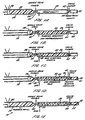
- FIGS 1A - 1E illustrate the sequence steps of an embodiment of the present invention. This process is referred to generally by the reference numeral 10 in the drawings.
- a quantity of molten plastics material 20 is positioned in the barrel 22 of an injection moulding machine.
- the injection moulding machine can be of any conventional type and can expel the plastics material from the nozzle of the barrel in any conventional manner, such as by a helical screw or a piston 26.
- a piston member 26 is shown and illustrated and described in Figures 1A - 1E, it is to be understood that any conventional mechanism used to expel the plastics material from a barrel of an injection moulding machine can be utilised.
- the nozzle 24 of the injection moulding machine is connected to a mould cavity 30.
- the mould cavity 30 is positioned in a conventional mould which in turn is positioned in a conventional moulding machine.
- the mould cavity 30 represents a thicker section of the article to be moulded.
- a secondary cavity 32 is positioned within the mould in communication with the mould cavity 30, and coupled to the mould cavity by a flow runner or conduit 44.
- a valve member 40 is positioned between the nozzle 24 and the mould cavity 30 while a second valve member 42 is positioned in the flow runner or conduit 44.
- the valve members 40 and 42 can be of any conventional type, but in this embodiment are shut-off type valve members, and can be operated in any conventional manner, such as pneumatically, hydraulically, electrically, etc. Control of the valve members 40 and 42 can also be accomplished with any conventional mechanism or system.
- the mechanism can be computer operated so that the valves can be accurately timed to open and close as desired in accordance with a prespecified injection moulding process.
- the quantity of plastics material 20 in the barrel 22 of the injection moulding machine is sufficient to fill or substantially fill the volume of the mould cavity 30.
- the plastics material 20 which can be used or utilised with the present invention can be of any conventional type, such as a thermoplastics resin.
- the plastics material can also be a filled material, that is mixed with a glass or mineral material.
- two or more secondary cavities can be provided.
- the secondary cavities are each connected to the mould cavity 30 by separate runners or conduits 44.
- independently controlled separate valve members are positioned in each of the runners or conduits 44 between the mould cavity 30 and the secondary cavities.
- the secondary cavities constitute overflow cavities, which can be filled separately and the valve members 42 are timed in order to allow the plastics material to be expelled as desired and where necessary in order to optimise the production process and plastics product produced by the process.
- the plastics resin material 20 is injected by the molten injection moulding machine into the mould cavity 30.
- valve member 40 is opened in order to allow plastics material to enter the mould cavity 30, but valve member 42 is retained in a closed position in order to prevent any plastics from entering the secondary cavity 32.
- the plastics in the mould cavity is then pressurised by the moulding machine ("packing pressure") for a short predetermined period of time, for example 1-5 seconds. This assists to ensure good reproducibility of the mould surface on the moulded article in the cavity.
- gas for example nitrogen
- inlet conduit 50 This is shown in Figure 1C.
- the valve member 42 remains in a closed condition for a predetermined amount of time such that the pressure of the gas creates a hollow cavity in the molten material 20 and forces the plastics material against the inner wall surfaces of the mould cavity, and an outer skin of the plastics material has solidified whilst a core portion of the plastics material remains molten, thereby helping to provide a good surface finish on the plastics product.
- valve member 40 is closed and the valve member 42 opened.
- the pressure of the gas 52 in the molten plastics material 20 in the mould cavity 30 causes a portion of the molten plastics to be expelled from the mould cavity into the secondary cavity 32.
- the molten plastics material is preferably expelled from the centre of the thicker sections in the mould article through the connecting gates or runner 44.
- a gas "hold” or “packing” pressure is maintained in the mould cavity whilst the remaining plastics material cools and solidifies. This takes in the order of 10-25 seconds or longer, depending on the size and thickness of the moulded plastics product.
- the volume of the or each secondary cavity 32 is determined by the time at which the valve member 42 is opened. If the valve opening time is prolonged, more of the plastics solidifies in the mould cavity, i.e. the solid skin of plastics will thicken, and less is expelled; conversely, if the valve opening time is advanced, i.e. the delay time in opening is reduced, the skin thickness is reduced and more plastics is expelled.
- the balance of secondary cavity volume and valve opening time is optimised, the process can be operated consistently shot-after-shot in production.
- the amount of plastics material which is expelled into the overflow cavity can also be controlled by the time at which the valve member 42 is opened.
- valve member 40 It is also possible to operate the present process with valve member 40 open or without use of a valve such as valve member 40 positioned between the injection moulding machine and the mould, by holding piston 26 in its forward position. However, it is preferable to close valve member 40 or an equivalent hot runner valve gate, to provide positive means for preventing plastics from being forced back into the screw or piston cylinder, i.e. the barrel 22, when pressurised by the gas.
- the gas 52 is exhausted, for example, back through conduit 50.
- the expelled gas can be either collected and reclaimed for further use, or expelled into the atmosphere.
- Mechanisms and systems for exhausting or venting pressurised gas from the interior of the moulded article preparatory to opening the mould are described in numerous patents in the prior art. In this regard, any conventional mechanism or system for exhausting or venting the gas from the mould and moulded article can be utilised in accordance with the present invention.
- the piston or ram 26 of the injection moulding machine is typically retracted to its rest position (as illustrated) in preparation for another shot of plastics material.
- the mould is opened and the finished plastics product is ejected or removed from the mould cavity.
- the expelled plastics material 21 in the secondary cavity 32 is similarly ejected or removed from the mould.
- the plastics in the secondary cavity 32 can be reground and reused, if desired, to avoid waste of material, or the cavity itself can be used to form another plastics part for possible use.
- the positioning of one or more injectors 50 in the mould cavity should preferably be adjacent to the thicker sections and remote from, and at the opposite extremity to, the expulsion gates and runners.
- commencement of gas injection from each gas feed position may be sequentially controlled by appropriate control means.
- the positioning of the plastics feed gate or gates, if more than one is provided, in the mould cavity should be selected to optimise the flow of plastics into the mould cavity. As explained above, it may be necessary to prevent in-mould gas pressure from forcing the plastics back into the injection moulding machine by using a shut-off valve 40, as illustrated, or by holding the ram screw forward, or by use of a hot runner system with valve gates.
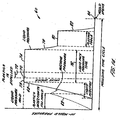
- FIG. 2 A graph illustrating the sequence of steps described above is shown in Figure 2.
- the graph is referred to generally by the reference numeral 60 in Figure 2 and charts the moulding cycle time relative to the pressure in the mould.
- the pressure in the mould initially increases as shown by line 62 as the plastics is injected into the mould cavity.
- the moulding machine then holds the plastics packed pressure as shown by line 64.
- the time at which the machine packs the pressure is indicated by the arrow 66. That time can be adjusted as desired.
- the gas is injected into the plastics material in the mould cavity.
- the valve member 44 regulating the flow of plastics material into the secondary cavity is opened. This allows plastics to be expelled from the mould cavity into the secondary cavity. This step is indicated by the arrow 72.
- the pressure of the gas in the mould cavity is held. This is shown by line 74.
- the time of the gas packing pressure is shown by the arrow 76 in Figure 2.
- the gas pressure is reduced in the mould. This is shown by line 78.
- the gas pressure can also be held constant for a period of time, as shown at 80, in order to allow the plastics material to cool and harden. Thereafter, that is once the plastics part is cooled and hardened, the gas is ejected from the mould. Once the pressure of the gas is vented or exhausted from the mould cavity, as shown by line 82, the mould is opened and the part removed. This is shown at point 84 on the graph of Figure 2.
- the method is not dependent on the injection of an accurately controlled shot volume of plastics repeatedly shot after shot. Also, the ability to pressure pack the plastics, due to volumetric contraction or shrinkage of the plastics, while the mould cavity is filled with plastics, or is filled with plastics and initial injection of gas, ensures accurate replication of the mould cavity surface without shrinkage of the plastics from the surface.
- the dependence on a fixed volume of plastics material which is expelled from the mould cavity eliminates the variable dependence on timing of the gas injection.
- the present invention is suitable for multi-cavity moulds, with each cavity being able to be connected to one or more secondary cavities, thereby eliminating any need to balance the flow of plastics in order to partially fill each mould cavity.
- the present invention is suitable for a wide range of thermoplastics resin materials, including glass-filled fibre materials which require early pressurisation in order to achieve acceptable surface finishes. Also, a more consistent and uniform wall section thickness is achievable throughout the length of the gas channel as a result of more positive control of the gas and plastic flows. The process is further operable on moulding machines which are not capable of accurately delivering consistent volumes of plastics material.
- the position of the or each gas injector in the mould cavity is not as critical as it is with other processes in which overflow cavities are utilised.
- the present invention is suitable for expelling plastics from more than one position in a mould cavity.
- the valve members into the secondary cavities can be sequentially opened and closed in order to optimise plastic expulsion and to avoid thick accumulations of plastics remaining in the moulded article.
- the injection of an unpressurised accurate shot weight or filling volume is not necessary.
- the timing of the gas injection is not as critical as in other processes.
- the packed pressure exerted by the moulding machine and subsequently the gas when the cavity is full of plastics material ensures a good reproducibility of the mould cavity and the moulded article itself. Flow and weld marks are reduced. Also, the appearance of hesitation marks, when partial filling of a cavity is desired, is also infrequent or minimised with the present invention.
- valve member 42 as well as any other valve members which are positioned between the mould cavity and respective secondary cavities, can be operated independently and timed to be sequential with the other secondary cavities. This allows the plastics to be expelled from the mould cavity in a desired sequence and in order to allow formation of various channels in various thicker sections or members of the moulded article. Also, as noted, the volume of plastics expelled from the mould cavity is not dependent on the timing of the gas injection. Instead, it is dependent on the timing of the valves and the volume of the secondary cavity or cavities and the opening and closing sequence of the valve members from the mould cavity into the secondary cavities.
- valves in the flow runners or conduits between the mould cavity and the secondary cavity or cavities can be operated in a different manner.
- the valve members may be operable by the application of a selected pressure which is exerted by the injection of gas and in turn a transmission of pressure to the plastics material. This in turn will open the valve member, thus overcoming a preset closing force.
- the present closing forces may be applied to the valve members by mechanical spring members or other means, such as pneumatic, hydraulic, or electric.
- opening and closing of the valve members may be controlled by any conventional means, such as pneumatic, hydraulic, electrical, or mechanical means.
- the opening and closing of the valve members can also be controlled by external means which may include digital or computer timing, external or integral with the gas pressure control means.
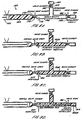
- Figures 3A - 3E illustrate the same apparatus as in the embodiment of Figures 1A - 1E, but an alternative sequence of steps of a process for injection moulding a hollow plastics article.
- the quantity of molten plastics material 20 in the barrel 22 of the injection moulding machine is at least sufficient to fill or substantially fill the volume of the mould cavity 30 without packing the plastics material in the mould cavity.
- the second step in the process is shown in Figure 3B.
- the molten plastics resin material 20 is injected by the injection moulding machine into the mould cavity 30, with valve member 40 open and valve member 42 closed, but the step of injecting the plastics material is completed before packing of the plastics material in the mould cavity occurs.
- pressurised gas e.g. nitrogen
- inlet conduit 50 is injected at selected ram and hold pressures through inlet conduit 50.
- pressurised gas e.g. nitrogen
- the valve member 42 remains in a closed condition for a predetermined amount of time such that the pressure of the gas creates a hollow cavity in the molten material 20 and applies a packing pressure which forces the plastics material against the inner surfaces of the mould cavity 30, and an outer skin of the plastics material has solidified whilst a core portion of the plastics material remains molten, thereby helping to provide a good surface finish on the plastics product.
- valve member 42 is opened.
- the pressure of the gas 52 in the molten plastics material 20 in the mould cavity 30 causes a portion of the molten plastics to be expelled from the mould cavity into the secondary cavity 32.
- the molten plastics material is preferably expelled from the centre of the thicker section or sections in the moulded article through the connecting conduit or runner 44.
- a gas "hold” or “packing” pressure is maintained in the mould cavity while the plastics material cools and solidifies.
- the gas 52 is exhausted. This is shown in Figure 3E. Thereafter, the mould is opened and the finished plastics article is ejected or removed from the mould cavity. At the same time, the expelled plastics material 21 in the or each secondary cavity 32 is similarly ejected or removed from the mould.
- FIG. 4 A graph illustrating the sequence of steps described above is shown in Figure 4.
- the graph is referred to generally by the reference numeral 60 in Figure 4 and charts the moulding cycle time relative to the pressure in the mould.
- the pressure in the mould initially increases as shown by line 62 as the plastics is injected into the mould cavity, without the moulding machine holding the plastics pressure to pack the plastics.
- the gas is injected into the plastics material in the mould cavity and applies a packing pressure to the plastics material as shown by line 73.
- the valve member 44 regulating the flow of plastics material into the secondary cavity is opened. This allows plastics to be expelled from the mould cavity into the secondary cavity. This step is indicated by the arrow 72.
- the pressure of the gas in the mould cavity is held. This is shown by line 74.
- the time of the gas packing pressure is shown by the arrow 76 in Figure 4.
- the gas pressure is reduced in the mould. This is shown by line 78.
- the gas pressure can also be held constant for a period of time, as shown at 80, in order to allow the plastics material to cool and harden. Thereafter, that is once the plastics article is cooled and hardened, the gas is ejected from the mould. Once the pressure of the gas is vented or exhausted from the mould cavity, as shown by line 82, the mould is opened and the moulded article removed. This is shown at point 84 on the graph of Figure 4.
- the ability to pressure pack the plastics during initial injection of gas assists replication of the mould cavity surface without shrinkage of the plastics from the surface.
- plastics material 102 is positioned in a barrel 104 of an injection moulding machine 101.
- the barrel 104 has a nozzle 106 which is connected in any conventional manner with a mould cavity 108.
- a valve member 110 controls the flow of plastics from the barrel member into the mould cavity.
- valve member 110 is opened allowing plastics material to be injected from the barrel 104 into the mould cavity 108. Thereafter, the pressure is temporarily held by the injection moulding machine relative to the plastics in the mould cavity 108, preferably for at least 1-5 seconds.
- gas injection begins through gas injection conduit 120, the gas creating a hollow cavity in the plastics material and forcing the plastics material against the inner surfaces of the mould cavity.
- An outer skin of the plastics material becomes solidified whilst a core portion of the plastics material remains molten.
- gas injection conduit 120 gas injection conduit 120
- valve member 110 open.
- the gas 122 expels a portion of the plastics back into the machine cylinder or barrel 104 and extends the hollow cavity in the plastics material in the mould cavity 108.
- the pressure is reduced from the moulding machine screw or plunger member 130 which enables expulsion of molten plastics material 102 from the mould cavity back into the machine cylinder or barrel 104.
- Space in the barrel 104 can be formed by the pressure of the gas forcing the plunger member 130 away from the mould.
- FIG. 6A An alternative process is shown in Figures 6A - 6E and referred to generally by the reference numeral 100.
- a quantity of molten plastics material 102 is positioned in barrel 104 of injection moulding machine 101, and the apparatus is the same as the apparatus illustrated in Figure 5A.
- the valve member 110 is opened allowing molten plastics material to be injected from the barrel 104 into the mould cavity 108 without packing the plastics.
- gas injection step is commenced. This is achieved either with the piston 130 of the moulding machine held forward and the valve member 110 open, or with the valve member 110 closed as shown in Figure 6C. In either case, gas is injected through conduit 120 and begins to create a hollow cavity in the plastics material in the mould cavity 108 thereby packing the plastics in the mould cavity.
- the step of expelling a portion of the plastics material back into the barrel 104 is controlled so that a predetermined amount of plastics is expelled in a controlled manner.
- Controlling the flow of plastics may be achieved by maintaining a back pressure on the piston 130 whilst controlling the speed at which the pressure of the plastics retracts the piston and/or controlling the final position of the piston.
- the amount of plastics which is expelled may be controlled first by controlling the speed at which the pressure of plastics retracts the piston whilst maintaining a back pressure on the piston, and subsequently closing the nozzle valve 110. In each case, the flow of gas does not extend beyond the nozzle valve 110, to avoid fouling of the plastics in the barrel which is injected into the mould cavity 108 during the succeeding moulding cycle.
- the gas pressure is held during cooling and solidification of the remaining plastics material in the mould cavity.
- the plastics is subjected to packing pressure by the gas and has its surface forced tightly against the inner wall surfaces of the mould cavity. This produces a good surface finish and creates a full definition of the surface of the mould.
- the gas pressure in the mould cavity is reduced under control to atmospheric pressure. This is shown in Figure 6E.
- the machine barrel 104 is completely refilled with plastics material ready for the next moulding cycle.
- the mould is opened and the moulded plastics article is removed or ejected from the mould.
- the expelled plastics can be remoulded in succeeding shots. Also, retrimming of the moulding is not necessary, and the system does not have to expend the cost of additional shut-off valves in the runner members to separate secondary cavities.
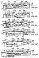
- FIG. 7A- 7F An embodiment of the invention in which more than one secondary cavity is utilised is shown in Figures 7A- 7F and designated generally by the reference numeral 150.
- the embodiment 150 includes an injection moulding machine 152 which is set up to inject a quantity of molten plastics material 154 into a mould cavity 156 in a mould.
- the primary mould cavity 156 has a pair of secondary cavities 158 and 160 which are connected to the mould cavity 156 by conduits or runners 162 and 164 respectively.
- Valve members 166 and 168 are positioned in the conduits and act to open and close the flow plastics from the mould cavity 156 to the secondary cavities.
- valve member 170 is positioned at the inlet to the primary mould cavity 156 (or in the nozzle) and used to open and close the conduit 172 which connects the injection moulding machine nozzle to the mould cavity.
- Port or pin member 174 is used to inject gas into the mould cavity.
- FIGs 7A - 7F The sequence of steps for use of system 150 is illustrated in Figures 7A - 7F.
- Molten plastics material 154A is first injected into the mould cavity and retained there for a brief period of "packing pressure" (Figure 7B).
- Gas 180 is then injected into the plastics material in the mould cavity and the pressure is held for an amount of time which ensures that the plastics material is held against the inner wall surfaces of the mould cavity and an outer skin of the plastics material has solidified whilst a core portion of the plastics material remains molten (Figure 7C).
- Valve member 166 is then opened and a first quantity of plastics material 154B is expelled into a first secondary cavity 158 ( Figure 7D).
- valve member 168 is opened and a second quantity of plastics material 154C is expelled into a second secondary cavity 160 ( Figure 7E).
- the gas is exhausted back through port 174 ( Figure 7F).
- the mould is opened, the part is ejected, and the system is prepared for the start of another cycle.
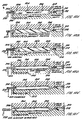
- FIG. 8A An alternative embodiment in which more than one secondary cavity is utilised is shown in Figures 8A - 8F and designated generally by the reference numeral 150.
- an injection moulding machine 152 is set up to inject a quantity of molten plastics material 154 into a mould cavity 156 in a mould.
- valve member 168 is opened and a second quantity of plastics material 154C is expelled into a second secondary cavity 160 ( Figure 8E).
- the gas is exhausted back through port 174 ( Figure 4F).
- the mould is opened, the part is ejected, and the system is prepared for the start of another cycle.
- FIGS 7A - 7F and Figures 8A - 8F are representative of embodiments in accordance with the present invention in which more than one secondary cavity is utilised. Variations and changes can be made by persons of ordinary skill in the art to develop other multiple secondary cavity systems. It is often advantageous to expel portions of the plastics material into second, third, or even fourth secondary cavities in order to relieve thick sections of the plastics remaining after the first expulsion. This can be evident in a non-uniformly thick section moulding such as an automobile door handle.
- valve member 42 as well as any other valve members which are positioned between the mould cavity and the secondary cavities, can be operated independently and timed to be sequential with the other secondary cavities. This allows the plastics to be expelled from the mould cavity in a desired sequence and in order to allow formation of various channels in various thicker sections or members of the product. Also, as noted above, the volume of plastics expelled from the mould cavity is not dependent on the timing of the gas. Instead, it is dependent on the timing of the valves and the volume of the secondary cavity or cavities, and the opening and closing sequence of the valve members from the mould cavity into the secondary cavities.
- valves in the runners or conduits between the mould cavity and the secondary cavity or cavities can be operated in a different manner.
- the valve members may be operable by the application of a selected pressure which is exerted by the injection of gas and in turn a transmission of pressure to the plastics material. This in turn will open the valve member, thus overcoming a preset closing force.
- the preset closing forces may be applied to the valve members by mechanical spring members or other means, such as pneumatic, hydraulic, or electric.
- opening and closing of the valve members may be controlled by any conventional means, such as pneumatic, hydraulic, electrical, or mechanical means.
- the opening and closing of the valve members can also be controlled by external means which may include digital or computer timing, external or integral with the gas pressure control means.
- the present invention also can be used in the manufacture of hollow tubular components.
- a preferred moulding system and process for this is shown in Figures 9A - 9F, while other embodiments of portions of this mechanism and system are illustrated in Figures 11 and 12.
- the tubular components can be used, for example, as rollers for printers.
- the tubular components have to be dimensionally stable and straight circular cross-sections with concentric hollow intersections in many cases.
- concentricity and uniformity of wall section can be achieved.
- the plastics and gas flows are controlled in an axial direction, and there is no random or uncontrolled sideways movement or turbulence in the plastics flow.
- the gas flows axially at the centre of the tubular section and is utilised to expel the plastics uniformly throughout the length of the tube into the secondary cavity or cavities. There is no lateral movement of the plastics after forming and within the semi-molten skin adjacent to the mould cavity surface.
- a uniform rate of cooling is achieved since there is good temperature control of the mould cavity members and there is a good plastics to mould surface contact to ensure uniform conduction of heat from the plastics.
- a mould cavity which has a circular middle section and two cone-shaped configurations at the two ends.
- the molten plastics is injected through a peripheral film gate from a runner surrounding the gate section feeding into the apex of the cone at the inlet end.
- the plastics is injected along a thinner section and it flows and expands gradually along a cone or cone-like configuration up to the maximum required cylindrical section. Thereby the plastics maintains contact with the surfaces of the mould cavity as the mould cavity is filled.
- the gas is injected in a central position along the axis of the tube and used to expel the plastics from the centre.
- the gas is injected near the apex of the cone in order to allow a gradual expansion into the desired intersection of the plastics.
- the speed of plastics injection is controlled from an initially slow rate and increased to a faster rate after the cone is filled and as the plastics completes the filling of the cylindrical section. The speed of the plastics injection slows again before the final cavity filling is completed.
- the control of the gas injection speed, and therefore the pressure is also controlled such that the gas is injected at a low pressure before expulsion of the plastics begins. This means that the pressure in which the gas is injected is lower before the opening of the valve in the runner or conduit which connects the mould cavity to the secondary cavity.
- the tubular section at the distal end of the mould cavity adjacent to the secondary cavity can be reduced in size to gradually reduce the flow of plastics to a thinner section. This allows the expulsion of the plastics to be controlled through the outflow runner and stop valve into the secondary cavity.
- a second cone-shaped cavity configuration is shown in the drawings and described below, but it is to be understood that any shape or configuration can be utilised at the distal end of the mould cavity. However, it is preferred that the cross-sectional size be reduced at the distal end of the cavity.
- FIG. 9A - 9F A sequence of steps which can be utilised in the plastics expulsion process in order to manufacture hollow tubular components is shown in Figures 9A - 9F.
- the process is generally referred to by the reference numeral 200 in the drawings.
- the mould cavity 202 generally has a central elongated portion or section 204, a cone shaped configuration 206 at the leading end (that is the entrance at which the gas and plastics are injected into the cavity), and preferably a corresponding cone-shaped configuration 208 at the distal end adjacent a secondary cavity 210.
- a valve member 212 is positioned in the conduit or runner connecting the mould cavity 202 with the secondary cavity 210.
- the valve member can be any conventional type, such as those described above with reference to Figures 1 to 8.
- the valve member may also have a tapered leading edge, as illustrated in Figures 9A - 9F.
- runner 220 and film gate 222 Detailed versions of the plastics feed runner 220 and the plastics gate 222 are better shown in Figures 11 and 12.
- the gas is injected into the mould cavity from gas injector port 230 which is positioned at the apex of the cone-shaped inlet section 206. Gas is directed to the port 230 from conduit or inlet line 232.
- the sequence of the moulding process includes the initial injection of molten plastics material into the mould cavity 202. At this point, the valve member 212 is closed. After the plastics is injected into the mould cavity, the plastics is pressurised or packed in the cavity in order to provide good surface characteristics of the outer surface of the moulded component. In this regard, the plastics is pressurised and compacted for a short dwell period of time of the order of 1-5 seconds by the moulding machine. This ensures good reproducibility of the mould surface on the moulded product or article and good replications of the mould cavity shape.
- the gas which is shown schematically by the reference numeral 250, creates a cavity in the plastics material, and continues to apply pressure within the plastics in the mould cavity 202.
- the valve member 212 is opened.
- the gas pressure within the inner tubular channel is maintained so that the outer surface of the plastics remains in contact uniformly with the mould cavity surface, thereby ensuring uniform conduction of heat from the plastics to the mould.
- the gas pressure is relieved and the gas is exhausted from the mould.
- Figure 9E Thereafter the movable core (if utilised) is removed from the mould cavity ( Figure 9F), and the mould is opened and the part ejected.
- the portion of the plastics material 252A in the secondary cavity 210 is also ejected at the same time.
- the plastics material in the secondary cavity can be reground and used again, can be scrapped, or can be made into another plastics component or part having the shape of the secondary cavity.
- the cone-shaped sections or configurations 206 and 208 of the mould cavity 202 preferably have included angles up to between 10-60 degrees. This assists in the uniform axial fill of the plastics from the apex of the cone and allows the plastics to expand up to the maximum cylindrical section as required in order to avoid turbulence or non-uniform flow of the plastics material.
- Injecting the gas at an axial direction from a gas injection assembly or port 230 mounted in a movable core assembly 240 enables the gas injector to be withdrawn axially from the moulded component before the mould is opened and the part is ejected.
- FIG. 10A An alternative process for moulding hollow tubular components is shown in Figures 10A - 10F.
- the apparatus is the same as shown in Figure 9A.
- plastics is introduced into the mould cavity 202 through runner 220, 222 and film gate 224, but without packing the plastics.
- the valve member 212 is closed ( Figure 10B).
- the injection of the gas is commenced.
- the gas which is shown schematically by the reference numeral 250, creates a cavity in the plastics material and continues to apply pressure within the plastics in the mould cavity 202.
- the valve member 212 is opened.
- the gas pressure within the inner tubular channel is maintained so that the outer surface of the plastics remains in contact uniformly with the mould cavity surface, thereby ensuring uniform conduction of heat from the plastics to the mould.
- the movable gas injector and plastics feed gate can be combined in order to feed the plastics to a ring gate configuration in which the plastics flows from a ringed runner 222 formed around the gas injector barrel, and then through a thinner ringed gate 224 flowing into the mould cavity so that it is coaxial with the gas injection when the gas is injected after the mould filling is complete. Thereby the plastics maintains contact with the surfaces of the mould cavity as the mould cavity is filled.
- Figure 12 An alternative configuration of the plastics runner can be utilised where the runner is formed by a groove between the enlarged movable core and the mould plate. This is illustrated in Figure 11.
- the gas is injected from a cone extension of the tubular component at the opposite end to the plastics feed gate section.
- the gas injector is mounted on a movable side core which injects the gas into the mould cavity in an axial direction, thereby expelling a uniform flow of plastics exiting from the cone-shaped feed section, through the feed gates, runners, and sprue and back into the machine cylinder.
- the gas pressure is maintained in the mould cavity in order to force the plastics against the surfaces of the mould cavity, which ensures good service replication and uniform conduction of heat from the plastics to the mould.
- the component can be moulded as one piece and can be moulded together with additional features, such as pulley wheels, gear wheels with profiled teeth, or with screw threads, grooves, or other profiles on the outer surface of the tubular section.
- additional features can be formed by machining applicable cavities for them in the mould cavity surfaces.
- a pressurised liquid instead of pressurised gas, to create a hollow cavity in the plastics material in the mould cavity as a result of volumetric contraction or shrinkage of the plastics material, and to apply a packing pressure.
- the packing pressure first creates a hollow cavity in the plastics material and applies a packing pressure which forces the plastics material against the inner surfaces of the mould cavity.
- the packing pressure is also held for a period of time which ensures that an outer skin of the plastics material has solidified whilst a core portion of the plastics material remains molten.
- the pressurised liquid expels a portion of the plastics material from the mould cavity into one or more secondary cavities and/or back into the injection machine barrel, the barrel constituting a secondary cavity.
- the liquid is conveniently water, but other liquids may be used, if desired.
- the use of cold water can also reduce the time of the cooling stage and thereby shorten the cycle time.
- Figures 13 and 14 are two graphs which correspond to Figures 2 and 4 respectively, for the use of liquid instead of gas as the pressurising fluid.
- the graph of Figure 13 includes the step of using the moulding machine to hold the plastics pressure to pack the plastics as shown by line 64.
- the time at which the machine packs the plastics is indicated by the arrow 66. That time can be adjusted as desired.
- the graph of Figure 14 illustrates the alternative process in which the mould cavity is filled with plastics material without the step of packing the plastics material before the injection of the pressurised liquid into the plastics material. Thereafter, the moulding cycle continues as described above in connection with Figure 4.
- One advantage of employing a liquid rather than a gas as the pressurising fluid is to provide a smoother internal wall surface within the plastics material, which is particularly desirable in the case of the tubular products of the above embodiments of Figures 9 to 12.
- Another advantage is that gas can tend to permeate into the wall of plastics material. Permeation is avoided or reduced by the use of liquid as the pressuring fluid.
- the secondary cavity or at least one secondary cavity is positioned in the mould, but upstream of the mould cavity, the secondary cavity being coupled to the flow runner or conduit through which the plastics is injected into the mould cavity.
- the secondary cavity or at least one secondary cavity is coupled to the mould cavity at a position within the mould cavity and near to the plastics feed position in the mould cavity.
- the gas or liquid injection position can then be positioned in the mould cavity and downstream of both the plastics feed position and the or each secondary cavity so that the expulsion of plastics material from the mould cavity is in a substantially contra direction to the flow of plastics material during the filling of the mould cavity.
Landscapes
- Engineering & Computer Science (AREA)
- Manufacturing & Machinery (AREA)
- Mechanical Engineering (AREA)
- Injection Moulding Of Plastics Or The Like (AREA)
- Moulds For Moulding Plastics Or The Like (AREA)
- Casting Or Compression Moulding Of Plastics Or The Like (AREA)
- Blow-Moulding Or Thermoforming Of Plastics Or The Like (AREA)
Abstract
Description
- The present invention relates to a process and apparatus for injection moulding hollow plastics articles.
- Injection moulding of plastics materials is well known and widely practised as a means of manufacturing an ever-increasing diversity of plastics components for industrial and consumer use. During the last two decades, versions of the process globally referred to as "gas assisted moulding" have been developed and used to overcome some of the problems inherent in conventional injection moulding, and to reduce costs and improve the quality of the final products.
- In conventional gas assisted injection moulding, a gas, such as nitrogen, is injected into the molten plastics material after it has entered the mould cavity. The low viscosity gas flows into the paths of least resistance within the more viscous plastics, thereby forming hollow channels within the plastics. The process is particularly beneficial for thick section mouldings, such as handles, and weight savings of up to 45% or more can result. Also, the moulding time cycles can be substantially reduced. In multi-section mouldings, the injected gas tends to flow into the thicker sections, again forming hollow continuous channels through which pressure may be transmitted through the medium of the gas. This adds to the scope of the designer and removes some of the design restrictions of conventional moulding.
- One conventional gas assisted plastics moulding process partially fills the mould cavity with an accurately controlled shot volume of plastics. Gas is then injected in order to continue the flow of plastics so that the cavity is filled with plastics and gas. The gas is used to exert outward pressure on the plastics material forcing it against the mould cavity surfaces, thereby achieving a good replication of the mould surface on the plastics moulded surface. After the plastics has solidified, the gas pressure is reduced by exhausting the gas to atmosphere, and the mould is opened and the part ejected. This is sometimes referred to as a "short shot" process.
- In another method, the mould cavity is completely or substantially filled with plastics material and then instead of injecting or packing more plastics into the cavity to compensate for the volumetric shrinkage of the plastics as it cools and solidifies, gas is injected into the plastics so that the gas expansion compensates for the plastics contraction. In practice, the initial gas penetration will continue to expand during the cooling cycle while the plastics is shrinking in volume. This is sometimes referred to as a "full shot" process.
- In the "full shot" process, it is sometimes difficult to achieve sufficient gas penetration along intended gas channels because there is insufficient volumetric shrinkage of the plastics to provide space for the gas. In such cases, a method of enabling some plastics to outflow from the mould cavity into overflow wells or "secondary" cavities is helpful in providing space for the gas expansion.
- In the "short shot" method, some mouldings may also be difficult to fill with plastics and gas to the extremities of the mould cavity. If the shot volume is too little, the gas may break through the leading edge of the plastics material during filling, thereby losing control of the gas. If the shot volume is too high, the gas will not reach the extremities of the mould cavity. Therefore thick section mouldings using the "short shot" process can also benefit from an additional displacement of plastics from the mould cavity into an overflow cavity.
- A method of at least partially filling the mould cavity before injection of the gas and employing an overflow cavity is described in U.S. Patent No. 5,098,637. However, in order to use the method of this patent successfully, it is necessary to accurately control the shot volume for both "short shot" and "full shot" methods, because there is no resistance to prevent the plastics from flowing into and filling the overflow cavity before the gas is injected.
- In the "short shot" process, the flow of plastics is temporarily stopped at the end of the filling sequence, and then typically there is a delay of up to five seconds before injection of the gas urges the plastics forward to complete the filling of the article cavity with plastics and gas and the overflow cavity with plastics. In the "full shot" process, the mould cavity is filled with, or substantially filled with, molten plastics and the gas is injected to compensate for the volumetric shrinkage of the plastics and to displace plastics into the overflow cavity. In both cases, since the runner to the overflow cavity is open, it is not feasible to apply "packing pressure" to the plastics in the mould cavity before displacement of the plastics into the overflow cavity occurs i.e. there is nothing to restrain the further flow of plastics. Furthermore, in the "short shot" process, or when nearly filling the cavity in a "full shot" process, there may remain unsightly visible hesitation lines or marks on the moulding surface at the position of the first plastics injection.
- Another method is disclosed in Japanese Patent Application No. 50-74660, in which a shut-off valve is positioned in a runner connecting the mould cavity and a "secondary cavity". In this application, the mould cavity is filled with thermoplastics resin and then a core resin or gas is injected into the mould cavity while thermoplastics resin is expelled from the mould cavity.
- It is known from FR 1.145.441 to introduce a plastics material into a mould cavity. Once the filling of the cavity is completed and after the plastics material has been given time to solidify in contact with the walls of the mould, the injection of a gas into the inside of the mould cavity, if done with sufficient pressure, can remove the still-liquid or semi-liquid material from the mould.
- According to one aspect of the invention there is provided a process for injection moulding a hollow plastics article comprising the steps of injecting a quantity of molten plastics material into a mould cavity at least to substantially fill the mould cavity; injecting pressurised gas or pressurised liquid into the plastics material in the mould cavity; allowing a portion of the molten plastics material in the mould to be expelled into at least one secondary cavity coupled to the mould cavity; permitting the remaining plastics material in the mould cavity to solidify; exhausting the gas or liquid from the mould cavity; and removing the plastics article from the mould; characterised by holding the pressure of the gas or liquid on the plastics material in the mould cavity for a period of time in order to apply a packing pressure to the plastics material before allowing a portion of the plastics material to be expelled into said at least one secondary cavity; wherein the step of holding the pressure of the gas or liquid on the plastics material in the mould cavity ensures that the plastics material is held against a wall surface of the mould cavity and an outer skin of the plastics material has solidified whilst a core portion of the plastics material remains molten.
- In one embodiment the step of injecting plastics material into the mould cavity includes the step of applying a packing pressure to the plastics material.
- In another embodiment the process includes the step of applying a packing pressure to the plastics material injection pressure in the mould cavity, prior to the injection of the pressurised gas or liquid into the plastics material in the mould cavity. Preferably an injection moulding machine is employed to inject the plastics material into the mould cavity and to apply an initial packing pressure to the plastics material, the pressurised gas or liquid applying a further packing pressure to the plastics material in the mould cavity.
- Preferably the process comprises the step of applying the packing pressure to the plastics material injection pressure in the mould cavity for a predetermined amount of time prior to the injection of gas or liquid into the plastics material.
- Preferably the expulsion step is achieved by opening a valve in a flow runner or conduit connecting the mould cavity to the or each secondary cavity whilst maintaining gas or liquid pressure in the mould cavity.
- In one embodiment the plastics article to be moulded has at least one section which is thicker than other sections and the charge of pressurised gas or liquid is introduced into the thicker section in order to form a hollow portion therein.
- The process may include the step of adjusting the volume of the at least one secondary cavity in order to allow expulsion of a predetermined amount of plastics material from the mould cavity.
- Portions of the plastics material may be expelled into at least two subsidiary cavities.
- In one embodiment at least two secondary cavities are provided and the step of allowing portions of the plastics material in the mould to be expelled into the secondary cavities comprises opening valve members positioned in respective flow runners or conduits connecting the mould cavity with the secondary cavities. The process may further comprise the step of sequentially controlling the opening of the valve members in order to allow selective expelling of plastics material into the at least two secondary cavities.
- In one embodiment the process is applied for injection moulding a hollow plastics tubular article, the mould cavity having a substantially cone-shaped inlet portion, an elongate central portion and an exit portion.
- Preferably said cone-shaped portion has an apex and said gas or liquid is injected into the plastics material at said apex.
- It is also preferred that said exit portion comprises a second substantially cone-shaped portion, said cone-shaped exit portion having an apex and said expulsion of plastics material from the mould cavity into the secondary cavity occurs through said apex.
- Preferably the plastics material is injected into the mould cavity at said cone-shaped inlet portion and maintains contact with the surfaces of the mould cavity as the mould cavity is filled.
- There may be provided a ring gate mechanism for injecting the plastics material into said cone-shaped inlet portion.
- The process preferably includes the step of trimming at least one end of the article to form a tubular article. Thereby the article may be trimmed to form a tubular article of substantially constant cross-section.
- The plastics material may be injected into the mould cavity from an injection moulding machine with a barrel and nozzle, and the process includes the step of allowing a portion of the plastics material in the mould to be expelled back into the barrel of the injection moulding machine, the barrel constituting the secondary cavity or one of the secondary cavities.
- According to another aspect of the invention there is provided a process for injection moulding a hollow plastics article utilising an injection moulding machine with a barrel and nozzle and a mould with a mould cavity therein having a shape defining at least a portion of the article, said process comprising the steps of injecting a quantity of molten plastics material into the mould cavity from the injection moulding machine at least to substantially fill the mould cavity; injecting pressurised gas or pressurised liquid into the plastics material in the mould cavity; allowing a portion of the molten plastics material in the mould to be expelled back into the barrel of the injection moulding machine; permitting the remaining plastics material in the mould cavity to solidify; exhausting the gas or liquid from the mould cavity; and removing the plastics article from the mould; characterised by holding the pressure of the gas or liquid on the plastics material in the mould cavity for a period of time in order to apply a packing pressure to the plastics material before allowing said portion of the plastics material in the mould to be expelled back into the barrel of the injection moulding machine.
- Preferably the step of holding the pressure of the gas or liquid on the plastics material in the mould cavity ensures that the plastics material is held against a wall surface of the mould cavity and an outer skin of the plastics material has solidified whilst a core portion of the plastics material remains molten.
- In one embodiment the step of injecting plastics material into the mould cavity includes the step of applying a packing pressure to the plastics material.
- In another embodiment the injection moulding machine is employed to apply a packing pressure to the plastics material injection pressure in the mould cavity, prior to the injection of pressurised gas or liquid into the plastics material.
- Preferably the step of allowing plastics material to be expelled back into the barrel of the injection moulding machine is controlled so that a predetermined amount is expelled in a controlled manner.
- In one embodiment, the amount of plastics material which is expelled is controlled by controlling the speed and/or the extent by which the plastics material retracts an injection piston or screw in the barrel of the injection moulding machine.
- Additionally or alternatively the amount of plastics material which is expelled is controlled by timing the closure of a shut-off valve member positioned in the flow path between the mould cavity and the barrel of the injection moulding machine.
- It is also preferred that the gas or liquid is injected into the plastics material at a location spaced from the nozzle of the injection moulding machine.
- Preferably the step of allowing a portion of the plastics material in the mould to be expelled back into the barrel of the injection moulding machine comprises opening a shut-off valve member positioned in the flow path between the mould cavity and the barrel of the injection moulding machine. The valve member is preferably included as part of the nozzle of the injection moulding machine.
- In one embodiment a first portion of plastics material in the mould is allowed to be expelled back into the barrel of the injection moulding machine, and the process comprises the step of also allowing a respective second portion of the plastics material in the mould to be expelled into one or more secondary cavities coupled to the mould cavity.
- Preferably the step of allowing one or more second portions of the plastics material to be expelled into a respective secondary cavity comprises opening a valve member positioned in the flow path between the mould cavity and the secondary cavity.
- The invention also provides apparatus for injection moulding a hollow plastics article comprising a mould with a mould cavity therein defining at least a portion of the article and at least one secondary cavity coupled to the mould cavity; means for injecting a quantity of molten plastics material into the mould cavity at least to substantially fill the mould cavity; and means for injecting pressurised gas or pressurised liquid into the plastics material in the mould cavity in order to apply a packing pressure to the plastics material; characterised in that control means are provided for holding the pressure of the gas or liquid on the plastics material in the mould cavity for a period of time in order to apply a packing pressure to the plastics material before allowing a portion of the molten plastics material in the mould to be expelled into said at least one secondary cavity, prior to the remaining plastics material in the mould cavity solidifying and the gas or liquid being exhausted from the mould cavity to allow the removal of the plastics article from the mould cavity; wherein the control means hold the pressure of the gas or liquid on the plastics material in the mould cavity for a period of time which ensures that the plastics material is held against a wall surface of the mould cavity and an outer skin of the plastics material has solidified whilst a core portion of the plastics material remains molten.
- In one embodiment an injection moulding machine is employed to inject the plastics material into the mould cavity and to apply a packing pressure to the plastics material.
- In another embodiment an injection moulding machine is employed to inject the plastics material into the mould cavity, and to apply a packing pressure to the plastics material injection pressure in the mould cavity, prior to the injection of the pressurised gas or liquid into the plastics material in the mould cavity.
- Preferably the or each secondary cavity is connected to the mould cavity by a flow runner or conduit containing a valve controlled by said control means.
- In one embodiment the mould cavity is coupled to at least two secondary cavities by a respective flow runner or conduit, each coupling containing a controlled valve.
- Preferably the means for injecting plastics material into the mould cavity is an injection moulding machine with a barrel and nozzle, the nozzle being flow connected to the mould cavity and the barrel constituting a further secondary cavity.
- Preferably a shut-off valve member is positioned in the flow path between the mould cavity and the barrel of the injection moulding machine. The valve member may be included as part of the nozzle of the injection moulding machine.
- For injection moulding a hollow plastics tubular article, the mould cavity preferably has a substantially cone-shaped inlet portion, an elongate central portion and an exit portion. Preferably the cone-shaped portion has an apex and the fluid is injected into the plastics material at the apex. The exit portion may comprise a second substantially cone-shaped portion, said cone-shaped exit portion having an apex and said expulsion of plastics material from the mould cavity into the secondary cavity occurs through said apex. There may be provided a ring gate mechanism for injecting the plastics material into said cone-shaped inlet portion.
- Means may be provided for trimming at least an end of the article to form a tubular article.
- The invention still further provides apparatus for injection moulding a hollow plastics article comprising an injection moulding machine with a barrel and a nozzle; a mould with a mould cavity therein defining at least a portion of the article, for connection to the nozzle for injecting a quantity of molten plastics material into the mould cavity from the injection moulding machine; and means for injecting pressurised gas or pressurised liquid into the plastics material in the mould cavity in order to apply a packing pressure to the plastics material; characterised in that control means are provided for holding the pressure of the gas or liquid on the plastics material in the mould cavity for a period of time in order to apply a packing pressure to the plastics material before allowing a portion of the molten plastics material in the mould to be expelled back into the barrel of the injection moulding machine, prior to the remaining plastics material in the mould cavity solidifying and the gas or liquid being exhausted from the mould cavity to allow the removal of the plastics article from the mould.
- In one embodiment the injection moulding machine is employed to inject the plastics material into the mould cavity and to apply a packing pressure to the plastics material.
- In another embodiment the injection moulding machine applies a packing pressure to the plastics material injection pressure in the mould cavity, prior to the injection of the pressurised gas or liquid into the plastics material in the mould cavity.
- By way of example, specific embodiments in accordance with the invention will be described with reference to the accompanying schematic drawings in which:-
- Figures 1A - 1E illustrate a sequence of steps in a first embodiment;
- Figure 2 is a graph further illustrating the in mould pressure time sequence as set forth in Figures 1A - 1E;
- Figures 3A - 3E illustrate an alternative sequence of steps to the embodiment of Figures 1A - 1E.
- Figure 4 is a graph further illustrating the in mould pressure time sequence as set forth in Figures 3A - 3E;
- Figures 5A - 5E illustrate a sequence of steps in another embodiment;
- Figures 6A - 6E illustrate an alternative sequence of steps to the embodiment of Figures 5A - 5E;
- Figures 7A - 7F illustrate a further embodiment of the invention in which two secondary cavities are utilised;
- Figures 8A - 8F illustrate an alternative sequence of steps to the embodiment of Figures 7A - 7F;
- Figures 9A - 9F illustrate a sequence of steps in a still further embodiment, particularly used for the manufacture of hollow tubular components;
- Figures 10A - 10F illustrate an alternative sequence of steps to the embodiment of Figures 9A - 9E;
- Figures 11 and 12 illustrate alternative embodiments at the entrance end of the hollow tubular component embodiment; and
- Figures 13 and 14 are graphs illustrating alternative in mould pressure time sequences when employing liquid as the pressurised fluid.
- Figures 1A - 1E illustrate the sequence steps of an embodiment of the present invention. This process is referred to generally by the
reference numeral 10 in the drawings. In Figure 1A, a quantity ofmolten plastics material 20 is positioned in thebarrel 22 of an injection moulding machine. The injection moulding machine can be of any conventional type and can expel the plastics material from the nozzle of the barrel in any conventional manner, such as by a helical screw or apiston 26. Although apiston member 26 is shown and illustrated and described in Figures 1A - 1E, it is to be understood that any conventional mechanism used to expel the plastics material from a barrel of an injection moulding machine can be utilised. - As shown in Figure 1A, the
nozzle 24 of the injection moulding machine is connected to amould cavity 30. Themould cavity 30 is positioned in a conventional mould which in turn is positioned in a conventional moulding machine. In this embodiment, themould cavity 30 represents a thicker section of the article to be moulded. Asecondary cavity 32 is positioned within the mould in communication with themould cavity 30, and coupled to the mould cavity by a flow runner orconduit 44. Avalve member 40 is positioned between thenozzle 24 and themould cavity 30 while asecond valve member 42 is positioned in the flow runner orconduit 44. Thevalve members valve members - The quantity of
plastics material 20 in thebarrel 22 of the injection moulding machine is sufficient to fill or substantially fill the volume of themould cavity 30. Theplastics material 20 which can be used or utilised with the present invention can be of any conventional type, such as a thermoplastics resin. The plastics material can also be a filled material, that is mixed with a glass or mineral material. - In an alternative embodiment, two or more secondary cavities can be provided. The secondary cavities are each connected to the
mould cavity 30 by separate runners orconduits 44. Also, independently controlled separate valve members are positioned in each of the runners orconduits 44 between themould cavity 30 and the secondary cavities. In this embodiment, the secondary cavities constitute overflow cavities, which can be filled separately and thevalve members 42 are timed in order to allow the plastics material to be expelled as desired and where necessary in order to optimise the production process and plastics product produced by the process. - Referring back to Figure 1, the second step in the process is shown in Figure 1B. In this step, the
plastics resin material 20 is injected by the molten injection moulding machine into themould cavity 30. For this process step,valve member 40 is opened in order to allow plastics material to enter themould cavity 30, butvalve member 42 is retained in a closed position in order to prevent any plastics from entering thesecondary cavity 32. The plastics in the mould cavity is then pressurised by the moulding machine ("packing pressure") for a short predetermined period of time, for example 1-5 seconds. This assists to ensure good reproducibility of the mould surface on the moulded article in the cavity. - At this point, the gas is injected at selected ram and hold pressures. As explained above, this is possible in the case of a full shot process due to the volumetric contraction or shrinkage of the plastics material in the
mould cavity 30. In the schematic embodiment shown, gas, for example nitrogen, is injected throughinlet conduit 50. This is shown in Figure 1C. Initially, thevalve member 42 remains in a closed condition for a predetermined amount of time such that the pressure of the gas creates a hollow cavity in themolten material 20 and forces the plastics material against the inner wall surfaces of the mould cavity, and an outer skin of the plastics material has solidified whilst a core portion of the plastics material remains molten, thereby helping to provide a good surface finish on the plastics product. - Thereafter, as shown in Figure 1D, the
valve member 40 is closed and thevalve member 42 opened. The pressure of the gas 52 in themolten plastics material 20 in themould cavity 30 causes a portion of the molten plastics to be expelled from the mould cavity into thesecondary cavity 32. In this regard, the molten plastics material is preferably expelled from the centre of the thicker sections in the mould article through the connecting gates orrunner 44. Thereafter, a gas "hold" or "packing" pressure is maintained in the mould cavity whilst the remaining plastics material cools and solidifies. This takes in the order of 10-25 seconds or longer, depending on the size and thickness of the moulded plastics product. - It is generally necessary to adjust the volume of the or each
secondary cavity 32 after the first or subsequent mould test trial in order to match the volume of the respective secondary cavity with the volume of plastics required to be expelled from the moulding cavity. This may be done by metal machining or removal from the mould to increase the volume, or addition of metal to reduce the volume. Initially, the volume of plastics expelled into the or each secondary cavity is determined by the time at which thevalve member 42 is opened. If the valve opening time is prolonged, more of the plastics solidifies in the mould cavity, i.e. the solid skin of plastics will thicken, and less is expelled; conversely, if the valve opening time is advanced, i.e. the delay time in opening is reduced, the skin thickness is reduced and more plastics is expelled. When the balance of secondary cavity volume and valve opening time is optimised, the process can be operated consistently shot-after-shot in production. - The amount of plastics material which is expelled into the overflow cavity can also be controlled by the time at which the
valve member 42 is opened. - It is also possible to operate the present process with
valve member 40 open or without use of a valve such asvalve member 40 positioned between the injection moulding machine and the mould, by holdingpiston 26 in its forward position. However, it is preferable to closevalve member 40 or an equivalent hot runner valve gate, to provide positive means for preventing plastics from being forced back into the screw or piston cylinder, i.e. thebarrel 22, when pressurised by the gas. - Once the remaining plastics material in the mould cavity has sufficiently cooled and solidified, the gas 52 is exhausted, for example, back through
conduit 50. This is shown in Figure 1E. The expelled gas can be either collected and reclaimed for further use, or expelled into the atmosphere. Mechanisms and systems for exhausting or venting pressurised gas from the interior of the moulded article preparatory to opening the mould are described in numerous patents in the prior art. In this regard, any conventional mechanism or system for exhausting or venting the gas from the mould and moulded article can be utilised in accordance with the present invention. At the same time that the gas is exhausted, the piston or ram 26 of the injection moulding machine is typically retracted to its rest position (as illustrated) in preparation for another shot of plastics material. - Once the gas is vented or exhausted from the mould cavity, the mould is opened and the finished plastics product is ejected or removed from the mould cavity. At the same time, the expelled
plastics material 21 in thesecondary cavity 32 is similarly ejected or removed from the mould. The plastics in thesecondary cavity 32 can be reground and reused, if desired, to avoid waste of material, or the cavity itself can be used to form another plastics part for possible use. - The positioning of one or
more injectors 50 in the mould cavity should preferably be adjacent to the thicker sections and remote from, and at the opposite extremity to, the expulsion gates and runners. In the case of two or more gas injectors in the mould cavity, the commencement of gas injection from each gas feed position may be sequentially controlled by appropriate control means. Also, the positioning of the plastics feed gate or gates, if more than one is provided, in the mould cavity, should be selected to optimise the flow of plastics into the mould cavity. As explained above, it may be necessary to prevent in-mould gas pressure from forcing the plastics back into the injection moulding machine by using a shut-offvalve 40, as illustrated, or by holding the ram screw forward, or by use of a hot runner system with valve gates. - A graph illustrating the sequence of steps described above is shown in Figure 2. The graph is referred to generally by the
reference numeral 60 in Figure 2 and charts the moulding cycle time relative to the pressure in the mould. In this regard, the pressure in the mould initially increases as shown byline 62 as the plastics is injected into the mould cavity. The moulding machine then holds the plastics packed pressure as shown byline 64. The time at which the machine packs the pressure is indicated by thearrow 66. That time can be adjusted as desired. - Thereafter, as shown by
line 68, the gas is injected into the plastics material in the mould cavity. Atpoint 70, thevalve member 44 regulating the flow of plastics material into the secondary cavity is opened. This allows plastics to be expelled from the mould cavity into the secondary cavity. This step is indicated by thearrow 72. Thereafter, the pressure of the gas in the mould cavity is held. This is shown byline 74. The time of the gas packing pressure is shown by thearrow 76 in Figure 2. - Subsequently, the gas pressure is reduced in the mould. This is shown by
line 78. The gas pressure can also be held constant for a period of time, as shown at 80, in order to allow the plastics material to cool and harden. Thereafter, that is once the plastics part is cooled and hardened, the gas is ejected from the mould. Once the pressure of the gas is vented or exhausted from the mould cavity, as shown byline 82, the mould is opened and the part removed. This is shown atpoint 84 on the graph of Figure 2. - With the system and process of the present invention, the method is not dependent on the injection of an accurately controlled shot volume of plastics repeatedly shot after shot. Also, the ability to pressure pack the plastics, due to volumetric contraction or shrinkage of the plastics, while the mould cavity is filled with plastics, or is filled with plastics and initial injection of gas, ensures accurate replication of the mould cavity surface without shrinkage of the plastics from the surface.
- Avoiding the need to partially fill the article cavity eliminates the tendency to form hesitation marks on the product at positions to which the plastics flows and stops before the gas is injected.
- The dependence on a fixed volume of plastics material which is expelled from the mould cavity eliminates the variable dependence on timing of the gas injection. Also, the present invention is suitable for multi-cavity moulds, with each cavity being able to be connected to one or more secondary cavities, thereby eliminating any need to balance the flow of plastics in order to partially fill each mould cavity.
- The present invention is suitable for a wide range of thermoplastics resin materials, including glass-filled fibre materials which require early pressurisation in order to achieve acceptable surface finishes. Also, a more consistent and uniform wall section thickness is achievable throughout the length of the gas channel as a result of more positive control of the gas and plastic flows. The process is further operable on moulding machines which are not capable of accurately delivering consistent volumes of plastics material.
- The position of the or each gas injector in the mould cavity is not as critical as it is with other processes in which overflow cavities are utilised. In this regard, the present invention is suitable for expelling plastics from more than one position in a mould cavity. Also, the valve members into the secondary cavities can be sequentially opened and closed in order to optimise plastic expulsion and to avoid thick accumulations of plastics remaining in the moulded article.
- With the present invention, the injection of an unpressurised accurate shot weight or filling volume is not necessary. Also, the timing of the gas injection is not as critical as in other processes. The packed pressure exerted by the moulding machine and subsequently the gas when the cavity is full of plastics material ensures a good reproducibility of the mould cavity and the moulded article itself. Flow and weld marks are reduced. Also, the appearance of hesitation marks, when partial filling of a cavity is desired, is also infrequent or minimised with the present invention.
- The operation of the
valve member 42, as well as any other valve members which are positioned between the mould cavity and respective secondary cavities, can be operated independently and timed to be sequential with the other secondary cavities. This allows the plastics to be expelled from the mould cavity in a desired sequence and in order to allow formation of various channels in various thicker sections or members of the moulded article. Also, as noted, the volume of plastics expelled from the mould cavity is not dependent on the timing of the gas injection. Instead, it is dependent on the timing of the valves and the volume of the secondary cavity or cavities and the opening and closing sequence of the valve members from the mould cavity into the secondary cavities. - In a further embodiment of the present invention, the valves in the flow runners or conduits between the mould cavity and the secondary cavity or cavities can be operated in a different manner. The valve members may be operable by the application of a selected pressure which is exerted by the injection of gas and in turn a transmission of pressure to the plastics material. This in turn will open the valve member, thus overcoming a preset closing force. The present closing forces may be applied to the valve members by mechanical spring members or other means, such as pneumatic, hydraulic, or electric.
- Further, the opening and closing of the valve members may be controlled by any conventional means, such as pneumatic, hydraulic, electrical, or mechanical means. The opening and closing of the valve members can also be controlled by external means which may include digital or computer timing, external or integral with the gas pressure control means.
- Figures 3A - 3E illustrate the same apparatus as in the embodiment of Figures 1A - 1E, but an alternative sequence of steps of a process for injection moulding a hollow plastics article.
- In this embodiment, the quantity of
molten plastics material 20 in thebarrel 22 of the injection moulding machine is at least sufficient to fill or substantially fill the volume of themould cavity 30 without packing the plastics material in the mould cavity. - Referring to Figure 3, the second step in the process is shown in Figure 3B. In this step, the molten
plastics resin material 20 is injected by the injection moulding machine into themould cavity 30, withvalve member 40 open andvalve member 42 closed, but the step of injecting the plastics material is completed before packing of the plastics material in the mould cavity occurs. - Following injection of the plastics material, with the
valve member 40 still closed, pressurised gas, e.g. nitrogen, is injected at selected ram and hold pressures throughinlet conduit 50. This is possible due to volumetric contraction or shrinkage of the plastics material and is shown in Figure 3C. Initially, thevalve member 42 remains in a closed condition for a predetermined amount of time such that the pressure of the gas creates a hollow cavity in themolten material 20 and applies a packing pressure which forces the plastics material against the inner surfaces of themould cavity 30, and an outer skin of the plastics material has solidified whilst a core portion of the plastics material remains molten, thereby helping to provide a good surface finish on the plastics product. - Thereafter, as shown in Figure 3D, the
valve member 42 is opened. The pressure of the gas 52 in themolten plastics material 20 in themould cavity 30 causes a portion of the molten plastics to be expelled from the mould cavity into thesecondary cavity 32. As before, the molten plastics material is preferably expelled from the centre of the thicker section or sections in the moulded article through the connecting conduit orrunner 44. Thereafter, a gas "hold" or "packing" pressure is maintained in the mould cavity while the plastics material cools and solidifies. - Once the remaining plastics material in the mould cavity has sufficiently cooled and solidified, the gas 52 is exhausted. This is shown in Figure 3E. Thereafter, the mould is opened and the finished plastics article is ejected or removed from the mould cavity. At the same time, the expelled
plastics material 21 in the or eachsecondary cavity 32 is similarly ejected or removed from the mould. - A graph illustrating the sequence of steps described above is shown in Figure 4. The graph is referred to generally by the
reference numeral 60 in Figure 4 and charts the moulding cycle time relative to the pressure in the mould. The pressure in the mould initially increases as shown byline 62 as the plastics is injected into the mould cavity, without the moulding machine holding the plastics pressure to pack the plastics. - Thereafter, as shown in
line 68, the gas is injected into the plastics material in the mould cavity and applies a packing pressure to the plastics material as shown byline 73. Atpoint 70, thevalve member 44 regulating the flow of plastics material into the secondary cavity is opened. This allows plastics to be expelled from the mould cavity into the secondary cavity. This step is indicated by thearrow 72. Thereafter, the pressure of the gas in the mould cavity is held. This is shown byline 74. The time of the gas packing pressure is shown by thearrow 76 in Figure 4. - Subsequently, the gas pressure is reduced in the mould. This is shown by
line 78. The gas pressure can also be held constant for a period of time, as shown at 80, in order to allow the plastics material to cool and harden. Thereafter, that is once the plastics article is cooled and hardened, the gas is ejected from the mould. Once the pressure of the gas is vented or exhausted from the mould cavity, as shown byline 82, the mould is opened and the moulded article removed. This is shown atpoint 84 on the graph of Figure 4. - The ability to pressure pack the plastics during initial injection of gas, assists replication of the mould cavity surface without shrinkage of the plastics from the surface.
- Also, avoiding the need to partially fill the mould cavity eliminates the tendency to form hesitation marks on the article at positions to which the plastics flows and stops before the gas is injected.
- Alternatively or additionally to expelling a portion of the plastics material into one or more secondary cavities, it is also possible to expel a portion of the plastics material back into the injection moulding machine barrel, the barrel thereby constituting a secondary cavity. This is accomplished by the gas pressure pushing back the injection screw or piston against a controllable back pressure. This process is shown in Figures 5A - 5E and referred to generally by the
reference numeral 100. As shown in Figure 5A,plastics material 102 is positioned in abarrel 104 of aninjection moulding machine 101. Thebarrel 104 has anozzle 106 which is connected in any conventional manner with amould cavity 108. Avalve member 110 controls the flow of plastics from the barrel member into the mould cavity. At the initial sequence of steps, as shown in Figure 5B, thevalve member 110 is opened allowing plastics material to be injected from thebarrel 104 into themould cavity 108. Thereafter, the pressure is temporarily held by the injection moulding machine relative to the plastics in themould cavity 108, preferably for at least 1-5 seconds. - With the machine screw or
plunger 130 held forward orvalve 110 closed, gas injection begins throughgas injection conduit 120, the gas creating a hollow cavity in the plastics material and forcing the plastics material against the inner surfaces of the mould cavity. An outer skin of the plastics material becomes solidified whilst a core portion of the plastics material remains molten. - Thereafter, as shown in Figure 5C, gas continues to be injected into the plastics material in the mould cavity through
gas injection conduit 120, with thevalve member 110 open. The gas 122 expels a portion of the plastics back into the machine cylinder orbarrel 104 and extends the hollow cavity in the plastics material in themould cavity 108. - At this point in the process, the pressure is reduced from the moulding machine screw or
plunger member 130 which enables expulsion ofmolten plastics material 102 from the mould cavity back into the machine cylinder orbarrel 104. Space in thebarrel 104 can be formed by the pressure of the gas forcing theplunger member 130 away from the mould. - Following completion of plastics expulsion, the gas pressure is held during cooling and solidification of the remaining plastics material in the mould cavity, and
valve member 110 is closed. This is shown in Figure 5D. At this point, the plastics is subjected to packing pressure and has its surface forced tightly against the inside surfaces of the mould cavity. This produces a good surface finish and creates a full definition of the surface of the mould. Thereafter, the gas pressure in the mould cavity is reduced under control to atmospheric pressure. This is shown in Figure 5E. Thereafter, themachine barrel 104 is completely refilled with plastics material, ready for the next moulding cycle. At the same time, the mould is opened and the formed plastics part is removed or ejected from the moulding machine. - The advantages of this alternative embodiment of the present invention is that the expelled plastics can be remoulded in succeeding shots. This eliminates regrinding or recovery of the expelled material from a spillover or secondary cavity. Also, retrimming of the moulding is not necessary, and the system does not have to expend the cost of additional shutoff valves in the runner members.
- An alternative process is shown in Figures 6A - 6E and referred to generally by the
reference numeral 100. As shown in Figure 6A, a quantity ofmolten plastics material 102 is positioned inbarrel 104 ofinjection moulding machine 101, and the apparatus is the same as the apparatus illustrated in Figure 5A. At the initial sequence of steps of this alternative process, as shown in Figure 6B, thevalve member 110 is opened allowing molten plastics material to be injected from thebarrel 104 into themould cavity 108 without packing the plastics. - Thereafter the gas injection step is commenced. This is achieved either with the
piston 130 of the moulding machine held forward and thevalve member 110 open, or with thevalve member 110 closed as shown in Figure 6C. In either case, gas is injected throughconduit 120 and begins to create a hollow cavity in the plastics material in themould cavity 108 thereby packing the plastics in the mould cavity. - After a predetermined time delay, whilst continuing to maintain gas pressure, the pressure is reduced from the moulding machine screw or
piston 130 and/or thevalve member 110 is opened, which enables the gas to progressively expel molten plastics material from themould cavity 108 back into the machine cylinder or barrel 104 (Figure 6D), the gas forcing thepiston 130 away from the mould. - The step of expelling a portion of the plastics material back into the
barrel 104 is controlled so that a predetermined amount of plastics is expelled in a controlled manner. Controlling the flow of plastics may be achieved by maintaining a back pressure on thepiston 130 whilst controlling the speed at which the pressure of the plastics retracts the piston and/or controlling the final position of the piston. Alternatively, the amount of plastics which is expelled may be controlled first by controlling the speed at which the pressure of plastics retracts the piston whilst maintaining a back pressure on the piston, and subsequently closing thenozzle valve 110. In each case, the flow of gas does not extend beyond thenozzle valve 110, to avoid fouling of the plastics in the barrel which is injected into themould cavity 108 during the succeeding moulding cycle. - Following completion of plastics expulsion, the gas pressure is held during cooling and solidification of the remaining plastics material in the mould cavity. At this point, the plastics is subjected to packing pressure by the gas and has its surface forced tightly against the inner wall surfaces of the mould cavity. This produces a good surface finish and creates a full definition of the surface of the mould. Thereafter, the gas pressure in the mould cavity is reduced under control to atmospheric pressure. This is shown in Figure 6E. Thereafter, the
machine barrel 104 is completely refilled with plastics material ready for the next moulding cycle. At the same time, the mould is opened and the moulded plastics article is removed or ejected from the mould. - As described above, the expelled plastics can be remoulded in succeeding shots. Also, retrimming of the moulding is not necessary, and the system does not have to expend the cost of additional shut-off valves in the runner members to separate secondary cavities.
- An embodiment of the invention in which more than one secondary cavity is utilised is shown in Figures 7A- 7F and designated generally by the
reference numeral 150. Theembodiment 150 includes aninjection moulding machine 152 which is set up to inject a quantity ofmolten plastics material 154 into amould cavity 156 in a mould. Theprimary mould cavity 156 has a pair ofsecondary cavities mould cavity 156 by conduits orrunners Valve members mould cavity 156 to the secondary cavities. Anothervalve member 170 is positioned at the inlet to the primary mould cavity 156 (or in the nozzle) and used to open and close theconduit 172 which connects the injection moulding machine nozzle to the mould cavity. Port orpin member 174 is used to inject gas into the mould cavity. - The sequence of steps for use of
system 150 is illustrated in Figures 7A - 7F.Molten plastics material 154A is first injected into the mould cavity and retained there for a brief period of "packing pressure" (Figure 7B).Gas 180 is then injected into the plastics material in the mould cavity and the pressure is held for an amount of time which ensures that the plastics material is held against the inner wall surfaces of the mould cavity and an outer skin of the plastics material has solidified whilst a core portion of the plastics material remains molten (Figure 7C).Valve member 166 is then opened and a first quantity of plastics material 154B is expelled into a first secondary cavity 158 (Figure 7D). Thereafter,valve member 168 is opened and a second quantity ofplastics material 154C is expelled into a second secondary cavity 160 (Figure 7E). Once the part has cooled and solidified sufficiently, the gas is exhausted back through port 174 (Figure 7F). In the final steps, the mould is opened, the part is ejected, and the system is prepared for the start of another cycle. - An alternative embodiment in which more than one secondary cavity is utilised is shown in Figures 8A - 8F and designated generally by the
reference numeral 150. As shown in Figure 8A, aninjection moulding machine 152 is set up to inject a quantity ofmolten plastics material 154 into amould cavity 156 in a mould. - The sequence of steps in this alternative embodiment is illustrated in Figures 8A - 8F.
Molten plastics material 154A is first injected into the mould cavity (Figure 8B) without packing of the plastics.Gas 180 is then injected into the plastics material in the mould cavity and the pressure is held for an amount of time which ensures that the plastics material is held against the inner wall surfaces of the mould cavity and an outer skin of the plastics material has solidified whilst a core portion of the plastics material remains molten (Figure 8C).Valve member 166 is then opened and a first quantity of plastics material 154B is expelled into a first secondary cavity 158 (Figure 8D). Thereafter,valve member 168 is opened and a second quantity ofplastics material 154C is expelled into a second secondary cavity 160 (Figure 8E). Once the part has cooled and solidified sufficiently, the gas is exhausted back through port 174 (Figure 4F). In the final steps, the mould is opened, the part is ejected, and the system is prepared for the start of another cycle. - The embodiments shown in Figures 7A - 7F and Figures 8A - 8F are representative of embodiments in accordance with the present invention in which more than one secondary cavity is utilised. Variations and changes can be made by persons of ordinary skill in the art to develop other multiple secondary cavity systems. It is often advantageous to expel portions of the plastics material into second, third, or even fourth secondary cavities in order to relieve thick sections of the plastics remaining after the first expulsion. This can be evident in a non-uniformly thick section moulding such as an automobile door handle.
- The operation of the
valve member 42, as well as any other valve members which are positioned between the mould cavity and the secondary cavities, can be operated independently and timed to be sequential with the other secondary cavities. This allows the plastics to be expelled from the mould cavity in a desired sequence and in order to allow formation of various channels in various thicker sections or members of the product. Also, as noted above, the volume of plastics expelled from the mould cavity is not dependent on the timing of the gas. Instead, it is dependent on the timing of the valves and the volume of the secondary cavity or cavities, and the opening and closing sequence of the valve members from the mould cavity into the secondary cavities. - In a further embodiment of the present invention, the valves in the runners or conduits between the mould cavity and the secondary cavity or cavities can be operated in a different manner. The valve members may be operable by the application of a selected pressure which is exerted by the injection of gas and in turn a transmission of pressure to the plastics material. This in turn will open the valve member, thus overcoming a preset closing force. The preset closing forces may be applied to the valve members by mechanical spring members or other means, such as pneumatic, hydraulic, or electric.
- Further, the opening and closing of the valve members may be controlled by any conventional means, such as pneumatic, hydraulic, electrical, or mechanical means. The opening and closing of the valve members can also be controlled by external means which may include digital or computer timing, external or integral with the gas pressure control means.
- The present invention also can be used in the manufacture of hollow tubular components. A preferred moulding system and process for this is shown in Figures 9A - 9F, while other embodiments of portions of this mechanism and system are illustrated in Figures 11 and 12. There is a need today for the manufacture of hollow tubular components from plastics materials. These components can be used, for example, as rollers for printers. The tubular components have to be dimensionally stable and straight circular cross-sections with concentric hollow intersections in many cases. It is also desirable to include features in the moulding which could normally not be extruded, but which are possible with injection moulded products. These include grooving or screw threads on the outer surface, brackets and other external fittings, connection mechanisms for use as spindles, and the inclusion of gear teeth or other configurations to provide ways to rotate the roller.
- With conventional injection moulding techniques, either as a solid section or with mechanically moving side cores to form the inter-tubular section, it is difficult to achieve flatness without distortion over the length of the component and to reduce moulding time cycles. In prior attempts to use gas assisted moulding for hollow products or components, it has proved difficult to achieve concentricity and uniform wall section thickness along the length of the tubular components.
- In order to achieve axial flatness over the length of the tubular section, uniform shrinkage of the plastics as it cools and changes from a liquid into a solid should be achieved. It is also important to eliminate or minimise stress in the moulding of the plastics since moulding stresses can cause ejected parts to distort or warp. Injection moulded plastics parts which have stress in them have a tendency to relieve that stress by distortion and warpage of the component after they are ejected from the mould.
- With the present invention, concentricity and uniformity of wall section can be achieved. The plastics and gas flows are controlled in an axial direction, and there is no random or uncontrolled sideways movement or turbulence in the plastics flow. The gas flows axially at the centre of the tubular section and is utilised to expel the plastics uniformly throughout the length of the tube into the secondary cavity or cavities. There is no lateral movement of the plastics after forming and within the semi-molten skin adjacent to the mould cavity surface. A uniform rate of cooling is achieved since there is good temperature control of the mould cavity members and there is a good plastics to mould surface contact to ensure uniform conduction of heat from the plastics.
- In order to achieve a flow of plastics without turbulence, a mould cavity is formed which has a circular middle section and two cone-shaped configurations at the two ends. The molten plastics is injected through a peripheral film gate from a runner surrounding the gate section feeding into the apex of the cone at the inlet end. The plastics is injected along a thinner section and it flows and expands gradually along a cone or cone-like configuration up to the maximum required cylindrical section. Thereby the plastics maintains contact with the surfaces of the mould cavity as the mould cavity is filled.
- The gas is injected in a central position along the axis of the tube and used to expel the plastics from the centre. The gas is injected near the apex of the cone in order to allow a gradual expansion into the desired intersection of the plastics. The speed of plastics injection is controlled from an initially slow rate and increased to a faster rate after the cone is filled and as the plastics completes the filling of the cylindrical section. The speed of the plastics injection slows again before the final cavity filling is completed.
- The control of the gas injection speed, and therefore the pressure, is also controlled such that the gas is injected at a low pressure before expulsion of the plastics begins. This means that the pressure in which the gas is injected is lower before the opening of the valve in the runner or conduit which connects the mould cavity to the secondary cavity.
- The tubular section at the distal end of the mould cavity adjacent to the secondary cavity can be reduced in size to gradually reduce the flow of plastics to a thinner section. This allows the expulsion of the plastics to be controlled through the outflow runner and stop valve into the secondary cavity. In this regard, a second cone-shaped cavity configuration is shown in the drawings and described below, but it is to be understood that any shape or configuration can be utilised at the distal end of the mould cavity. However, it is preferred that the cross-sectional size be reduced at the distal end of the cavity.
- A sequence of steps which can be utilised in the plastics expulsion process in order to manufacture hollow tubular components is shown in Figures 9A - 9F. The process is generally referred to by the
reference numeral 200 in the drawings. - As shown in Figure 9A, the
mould cavity 202 generally has a central elongated portion orsection 204, a cone shapedconfiguration 206 at the leading end (that is the entrance at which the gas and plastics are injected into the cavity), and preferably a corresponding cone-shapedconfiguration 208 at the distal end adjacent asecondary cavity 210. Avalve member 212 is positioned in the conduit or runner connecting themould cavity 202 with thesecondary cavity 210. The valve member can be any conventional type, such as those described above with reference to Figures 1 to 8. The valve member may also have a tapered leading edge, as illustrated in Figures 9A - 9F. - Plastics introduced into the
mould cavity 202 throughrunner 220 andfilm gate 222. Detailed versions of the plastics feedrunner 220 and theplastics gate 222 are better shown in Figures 11 and 12. - The gas is injected into the mould cavity from
gas injector port 230 which is positioned at the apex of the cone-shapedinlet section 206. Gas is directed to theport 230 from conduit orinlet line 232. - Also, as shown in Figures 11 and 12, it is possible to have a moving
core 240 as part of the mechanism and system. - As shown in Figure 9B, the sequence of the moulding process includes the initial injection of molten plastics material into the
mould cavity 202. At this point, thevalve member 212 is closed. After the plastics is injected into the mould cavity, the plastics is pressurised or packed in the cavity in order to provide good surface characteristics of the outer surface of the moulded component. In this regard, the plastics is pressurised and compacted for a short dwell period of time of the order of 1-5 seconds by the moulding machine. This ensures good reproducibility of the mould surface on the moulded product or article and good replications of the mould cavity shape. - Thereafter, as shown in Figure 9C, the injection of the gas is commenced. The gas, which is shown schematically by the
reference numeral 250, creates a cavity in the plastics material, and continues to apply pressure within the plastics in themould cavity 202. After a short dwell time in which the gas pressure is utilised to assist in forcing the plastics material against the internal walls or surfaces of the mould cavity and to ensure that an outer skin of the plastics material has solidified whilst a core portion of the plastics material remains molten, thevalve member 212 is opened. - With the
valve member 212 opened (Figure 9D), the molten plastics material in the centre of themould cavity 202 is allowed to be expelled from the mould cavity. The expulsion of the molten plastics is taken from the centre of the tubular section and enters thesecondary cavity 210 through the connectingrunner 214. In Figure 9D, the hollow centre of the tubular component, which is filled with gas, is indicated by thereference numeral 250, while the outer plastics now tubular component is referred to by thereference numeral 252. The plastics material in the secondary oroverflow cavity 210 is referred to by thereference numeral 252A. - When the expulsion of plastics is complete, the gas pressure within the inner tubular channel is maintained so that the outer surface of the plastics remains in contact uniformly with the mould cavity surface, thereby ensuring uniform conduction of heat from the plastics to the mould.
- After complete solidification of the plastics tubular component, the gas pressure is relieved and the gas is exhausted from the mould. This is shown in Figure 9E. Thereafter the movable core (if utilised) is removed from the mould cavity (Figure 9F), and the mould is opened and the part ejected. The portion of the
plastics material 252A in thesecondary cavity 210 is also ejected at the same time. In this regard, as indicated above, the plastics material in the secondary cavity can be reground and used again, can be scrapped, or can be made into another plastics component or part having the shape of the secondary cavity. - Once the plastics tubular component is formed and ejected from the mould, post moulding operations are necessary in order to trim off the cone sections at each end. This forms the final hollow tube or component.
- The cone-shaped sections or
configurations mould cavity 202 preferably have included angles up to between 10-60 degrees. This assists in the uniform axial fill of the plastics from the apex of the cone and allows the plastics to expand up to the maximum cylindrical section as required in order to avoid turbulence or non-uniform flow of the plastics material. - Injecting the gas at an axial direction from a gas injection assembly or
port 230 mounted in amovable core assembly 240 enables the gas injector to be withdrawn axially from the moulded component before the mould is opened and the part is ejected. - An alternative process for moulding hollow tubular components is shown in Figures 10A - 10F. The apparatus is the same as shown in Figure 9A. As before, plastics is introduced into the
mould cavity 202 throughrunner film gate 224, but without packing the plastics. At this point, thevalve member 212 is closed (Figure 10B). - Thereafter, as shown in Figure 10C, the injection of the gas is commenced. The gas which is shown schematically by the
reference numeral 250, creates a cavity in the plastics material and continues to apply pressure within the plastics in themould cavity 202. After a short dwell time in which the gas pressure is utilised to assist in forcing the plastics material against the internal walls or surfaces of the mould cavity, and to ensure that an the outer skin of the plastics material has solidified whilst a core portion of the plastics material remains molten, thevalve member 212 is opened. - With the
valve member 212 opened (Figure 10D), the molten plastics material in the centre of themould cavity 202 is allowed to be expelled from the mould cavity. The expulsion of the molten plastics is taken from the centre of the tubular section and enters thesecondary cavity 210 through the connectingrunner 214 acting as an overflow. - When the expulsion of plastics is complete, the gas pressure within the inner tubular channel is maintained so that the outer surface of the plastics remains in contact uniformly with the mould cavity surface, thereby ensuring uniform conduction of heat from the plastics to the mould.
- After cooling and solidification of the plastics tubular component, the gas pressure is relieved and the gas is exhausted or vented from the mould cavity. This is shown in Figure 10E. As before, the movable core (if utilised) is removed from the mould cavity (Figure 10F), and the mould is opened and the moulded article ejected.
- As an additional embodiment in the system and process of Figure 9 or Figure 10, the movable gas injector and plastics feed gate can be combined in order to feed the plastics to a ring gate configuration in which the plastics flows from a ringed
runner 222 formed around the gas injector barrel, and then through a thinner ringedgate 224 flowing into the mould cavity so that it is coaxial with the gas injection when the gas is injected after the mould filling is complete. Thereby the plastics maintains contact with the surfaces of the mould cavity as the mould cavity is filled. This is illustrated in Figure 12. An alternative configuration of the plastics runner can be utilised where the runner is formed by a groove between the enlarged movable core and the mould plate. This is illustrated in Figure 11. - It is possible in accordance with this hollow tubular embodiment to use either version of the plastics expulsion process as described above with respect to Figures 5A - 5E or Figures 6A - 6E. In either alternative embodiment, the molten plastics is expelled back into the moulding machine cylinder, as well as or instead of into a secondary cavity. The expelled plastics forces back the screw in the barrel of the moulding machine to provide the necessary controlled space volume within the cylinder.
- For these alternative embodiments, the gas is injected from a cone extension of the tubular component at the opposite end to the plastics feed gate section. The gas injector is mounted on a movable side core which injects the gas into the mould cavity in an axial direction, thereby expelling a uniform flow of plastics exiting from the cone-shaped feed section, through the feed gates, runners, and sprue and back into the machine cylinder. The gas pressure is maintained in the mould cavity in order to force the plastics against the surfaces of the mould cavity, which ensures good service replication and uniform conduction of heat from the plastics to the mould.
- In the manufacture of an injection moulded tubular structure of component, the component can be moulded as one piece and can be moulded together with additional features, such as pulley wheels, gear wheels with profiled teeth, or with screw threads, grooves, or other profiles on the outer surface of the tubular section. These additional features can be formed by machining applicable cavities for them in the mould cavity surfaces.
- In further embodiments, similar to each of the above, there is employed a pressurised liquid, instead of pressurised gas, to create a hollow cavity in the plastics material in the mould cavity as a result of volumetric contraction or shrinkage of the plastics material, and to apply a packing pressure. Again, the packing pressure first creates a hollow cavity in the plastics material and applies a packing pressure which forces the plastics material against the inner surfaces of the mould cavity. The packing pressure is also held for a period of time which ensures that an outer skin of the plastics material has solidified whilst a core portion of the plastics material remains molten. Subsequently the pressurised liquid expels a portion of the plastics material from the mould cavity into one or more secondary cavities and/or back into the injection machine barrel, the barrel constituting a secondary cavity. The liquid is conveniently water, but other liquids may be used, if desired. The use of cold water can also reduce the time of the cooling stage and thereby shorten the cycle time.
- Figures 13 and 14 are two graphs which correspond to Figures 2 and 4 respectively, for the use of liquid instead of gas as the pressurising fluid.
- The graph of Figure 13 includes the step of using the moulding machine to hold the plastics pressure to pack the plastics as shown by
line 64. The time at which the machine packs the plastics is indicated by thearrow 66. That time can be adjusted as desired. - Thereafter, as shown by
line 68, the pressurised liquid is injected into the plastics material in the mould cavity and applies a further packing pressure to the plastics material. The moulding cycle then continues as described above in connection with Figure 2. - The ability to pressure pack the plastics both while the mould cavity is filled with plastics, and while the mould cavity is filled with plastics and during initial injection of pressurised liquid, assists to ensure accurate replication of the mould surface without shrinkage of the plastics from the surface.
- The graph of Figure 14 illustrates the alternative process in which the mould cavity is filled with plastics material without the step of packing the plastics material before the injection of the pressurised liquid into the plastics material. Thereafter, the moulding cycle continues as described above in connection with Figure 4.
- One advantage of employing a liquid rather than a gas as the pressurising fluid is to provide a smoother internal wall surface within the plastics material, which is particularly desirable in the case of the tubular products of the above embodiments of Figures 9 to 12. Another advantage is that gas can tend to permeate into the wall of plastics material. Permeation is avoided or reduced by the use of liquid as the pressuring fluid.
- In a further embodiment, the secondary cavity or at least one secondary cavity is positioned in the mould, but upstream of the mould cavity, the secondary cavity being coupled to the flow runner or conduit through which the plastics is injected into the mould cavity.
- Alternatively or additionally, the secondary cavity or at least one secondary cavity is coupled to the mould cavity at a position within the mould cavity and near to the plastics feed position in the mould cavity.
- In either case, the gas or liquid injection position can then be positioned in the mould cavity and downstream of both the plastics feed position and the or each secondary cavity so that the expulsion of plastics material from the mould cavity is in a substantially contra direction to the flow of plastics material during the filling of the mould cavity.
Claims (65)
- A process for injection moulding a hollow plastics article comprising the steps of:(a) injecting a quantity of molten plastics material into a mould cavity at least to substantially fill the mould cavity;(b) injecting pressurised gas or pressurised liquid into the plastics material in the mould cavity;(c) allowing a portion of the molten plastics material in the mould to be expelled into at least one secondary cavity coupled to the mould cavity;(d) permitting the remaining plastics material in the mould cavity to solidify;(e) exhausting the gas or liquid from the mould cavity; and(f) removing the plastics article from the mould;
characterised by holding the pressure of the gas or liquid on the plastics material in the mould cavity for a period of time in order to apply a packing pressure to the plastics material before allowing a portion of the plastics material to be expelled into said at least one secondary cavity; wherein the step of holding the pressure of the gas or liquid on the plastics material in the mould cavity ensures that the plastics material is held against a wall surface of the mould cavity and an outer skin of the plastics material has solidified whilst a core portion of the plastics material remains molten. - The process as claimed in Claim 1, wherein the step of injecting plastics material into the mould cavity includes the step of applying a packing pressure to the plastics material.
- The process as claimed in Claim 1, including the step of applying a packing pressure to the plastics material injection pressure in the mould cavity, prior to the injection of the pressurised gas or liquid into the plastics material in the mould cavity.
- A process as claimed in Claim 3, wherein an injection moulding machine is employed to inject the plastics material into the mould cavity and to apply an initial packing pressure to the plastics material, the pressurised gas or liquid applying a further packing pressure to the plastics material in the mould cavity.
- The process as claimed in Claim 3 or Claim 4, comprising the step of applying the packing pressure to the plastics material injection pressure in the mould cavity for a predetermined amount of time prior to the injection of gas or liquid into the plastics material.
- A process as claimed in any one of the preceding claims, wherein the expulsion step is achieved by opening a valve in a flow runner or conduit connecting the mould cavity to the or each secondary cavity whilst maintaining gas or liquid pressure in the mould cavity.
- A process as claimed in any one of the preceding claims, wherein the plastics article to be moulded has at least one section which is thicker than other sections and the charge of pressurised gas or liquid is introduced into the thicker section in order to form a hollow portion therein.
- A process as claimed in any one of the preceding claims, including the step of adjusting the volume of said at least one secondary cavity in order to allow expulsion of a predetermined amount of plastics material from the mould cavity.
- A process as claimed in any one of the preceding claims, wherein portions of the plastics material are expelled into at least two secondary cavities.
- A process as claimed in any one of the preceding claims, wherein at least two secondary cavities are provided and the step of allowing portions of the plastics material in the mould to be expelled into the secondary cavities comprises opening valve members positioned in respective flow runners or conduits connecting the mould cavity with the secondary cavities.
- A process as claimed in Claim 10, further comprising the step of sequentially controlling the opening of the valve members in order to allow selective expelling of plastics material into the at least two secondary cavities.
- A process as claimed in any one of the preceding claims, wherein the process is applied for injection moulding a hollow plastics tubular article, the mould cavity having a substantially cone-shaped inlet portion, an elongate central portion and an exit portion.
- A process as claimed in Claim 12, wherein said cone-shaped portion has an apex and said gas or liquid is injected into the plastics material at said apex.
- A process as claimed in Claim 12 or Claim 13, wherein said exit portion comprises a second substantially cone-shaped portion, said cone-shaped exit portion having an apex and said expulsion of plastics material from the mould cavity into the secondary cavity occurs through said apex.
- A process as claimed in any one of Claims 12 to 14, wherein the plastics material is injected into the mould cavity at said cone-shaped inlet portion and maintains contact with the surfaces of the mould cavity as the mould cavity is filled.
- A process as claimed in Claim 15, including a ring gate mechanism for injecting the plastics material into said cone-shaped inlet portion.
- A process as claimed in any one of Claims 12 to 16, including the step of trimming at least one end of the article to form a tubular article.
- A process as claimed in Claim 17, wherein the article is trimmed to form a tubular article of substantially constant cross-section.
- A process as claimed in any one of the preceding claims, wherein said plastics material is injected into the mould cavity from an injection moulding machine with a barrel and nozzle, said process further comprising the step of allowing a portion of the plastics material in the mould to be expelled back into the barrel of the injection moulding machine, the barrel constituting the secondary cavity or one of the secondary cavities.
- A process for injection moulding a hollow plastics article utilising an injection moulding machine with a barrel and nozzle and a mould with a mould cavity therein having a shape defining at least a portion of the article, said process comprising the steps of:(a) injecting a quantity of molten plastics material into the mould cavity from the injection moulding machine at least to substantially fill the mould cavity;(b) injecting pressurised gas or pressurised liquid into the plastics material in the mould cavity;(c) allowing a portion of the molten plastics material in the mould to be expelled back into the barrel of the injection moulding machine;(d) permitting the remaining plastics material in the mould cavity to solidify;(e) exhausting the gas or liquid from the mould cavity; and(f) removing the plastics article from the mould;
characterised by holding the pressure of the gas or liquid on the plastics material in the mould cavity for a period of time in order to apply a packing pressure to the plastics material before allowing said portion of the plastics material to be expelled back into the barrel of the injection moulding machine. - A process as claimed in Claim 20, wherein the step of holding the pressure of the gas or liquid on the plastics material in the mould cavity ensures that the plastics material is held against a wall surface of the mould cavity and an outer skin of the plastics material has solidified whilst a core portion of the plastics material remains molten.
- A process as claimed in Claim 20 or Claim 21, wherein the step of injecting plastics material into the mould cavity includes the step of applying a packing pressure to the plastics material.
- A process as claimed in Claim 20 or Claim 21, wherein the injection moulding machine is employed to apply a packing pressure to the plastics material injection pressure in the mould cavity, prior to the injection of pressurised gas or liquid into the plastics material.
- A process as claimed in Claim 23, comprising the step of applying the packing pressure to the plastics material injection pressure in the mould cavity for a predetermined amount of time prior to the injection of gas or liquid into the plastics material.
- A process as claimed in any one of Claims 20 to 24, wherein the step of allowing plastics material to be expelled back into the barrel of the injection moulding machine is controlled so that a predetermined amount is expelled in a controlled manner.
- A process as claimed in Claim 25, wherein the amount of plastics material which is expelled is controlled by controlling the speed and/or the extent by which the plastics material retracts an injection piston or screw in the barrel of the injection moulding machine.
- A process as claimed in Claim 25 or Claim 26, wherein the amount of plastics material which is expelled is controlled by timing the closure of a shut-off valve member positioned in the flow path between the moulding cavity and the barrel of the injection moulding machine.
- A process as claimed in any one of Claims 20 to 27, wherein the gas or liquid is injected into the plastics material at a location spaced from the nozzle of the injection moulding machine.
- A process as claimed in any one of Claims 20 to 28, wherein said plastics article has at least one section which is thicker than other sections and said pressurised gas or liquid is introduced into the thicker section in order to form a hollow portion therein.
- A process as claimed in any one of Claims 20 to 29, wherein the step of allowing a portion of the plastics material in the mould to be expelled back into the barrel of the injection moulding machine comprises opening a shut-off valve member positioned in the flow path between the mould cavity and the barrel of the injection moulding machine.
- A process as claimed in Claim 30, wherein the valve member is included as part of the nozzle of the injection moulding machine.
- A process as claimed in any one of Claims 20 to 31, wherein a first portion of the plastics material in the mould is allowed to be expelled back into the barrel of the injection moulding machine, and comprising the step of allowing a respective second portion of the plastics material in the mould to be expelled into one or more secondary cavities coupled to the mould cavity.
- A process as claimed in Claim 32, wherein the step of allowing one or more second portions of the plastics material to be expelled into a respective secondary cavity comprises opening a valve member positioned in the flow path between the mould cavity and the secondary cavity.
- A process as claimed in any one of Claims 1 to 19 or Claim 32 or Claim 33, comprising injecting the plastics material along a flow path into the mould cavity, and allowing one or more portions of the plastics material to be expelled into a secondary cavity or cavities coupled to the flow path.
- A process as claimed in any one of Claims 1 to 19 or Claim 32 or Claim 33, wherein the or each secondary cavity is coupled to the mould cavity at a position within the mould cavity and near to the plastics feed position in the mould cavity.
- A process as claimed in Claim 34 or Claim 35, wherein the gas or liquid injection position is positioned in the mould cavity and downstream of the plastics feed position and the or each secondary cavity so that the expulsion of plastics material is in a substantially contra direction to the flow of plastics material during the filling of the mould cavity.
- A process as claimed in any one of the preceding claims, wherein at least two gas or liquid injecting positions are provided in one mould cavity.
- A process as claimed in Claim 37, including the step of sequentially controlling the commencement of gas or liquid injection from each gas or liquid feed position in the mould cavity.
- Apparatus for injection moulding a hollow plastics article comprising:a mould with a mould cavity therein defining at least a portion of the article and at least one secondary cavity coupled to the mould cavity;means for injecting a quantity of molten plastics material into the mould cavity at least to substantially fill the mould cavity; andmeans for injecting pressurised gas or pressurised liquid into the plastics material in the mould cavity;characterised in that control means are provided for holding the pressure of the gas or liquid on the plastics material in the mould cavity for a period of time in order to apply a packing pressure to the plastics material before allowing a portion of the molten plastics material in the mould to be expelled into said at least one secondary cavity, prior to the remaining plastics material in the mould cavity solidifying and the gas or liquid being exhausted from the mould cavity to allow the removal of the plastics article from the mould; the or each secondary cavity being connected to the mould cavity by a flow runner or conduit containing a valve controlled by said control means; wherein the control means hold the pressure of the gas or liquid on the plastics material in the mould cavity for a period of time which ensures that the plastics material is held against a wall surface of the mould cavity and an outer skin of the plastics material has solidified whilst a core portion of the plastics material remains molten.
- Apparatus as claimed in Claim 39, wherein an injection moulding machine is employed to inject the plastics material into the mould cavity and to apply a packing pressure to the plastics material.
- Apparatus as claimed in Claim 39, wherein an injection moulding machine is employed to inject the plastics material into the mould cavity, and to apply a packing pressure to the plastics material injection pressure in the mould cavity, prior to the injection of the pressurised gas or liquid into the plastics material in the mould cavity.
- Apparatus as claimed in Claim 41, wherein the control means are adapted to apply the packing pressure to the plastics material injection pressure in the mould cavity for a predetermined amount of time prior to the injection of gas or liquid into the plastics material.
- Apparatus as claimed in any one of Claims 39 to 42, wherein the mould cavity is coupled to at least two secondary cavities by a respective flow runner or conduit, each coupling containing a controlled valve.
- Apparatus as claimed in any one of Claims 39 to 43, wherein the means for injecting plastics material into the mould cavity is an injection moulding machine with a barrel and nozzle, the nozzle being flow connected to the mould cavity and the barrel constituting a further secondary cavity.
- Apparatus as claimed in Claim 44, including a shut-off valve member positioned in the flow path between the mould cavity and the barrel of the injection moulding machine.
- Apparatus as claimed in Claim 45, wherein the valve member is included as part of the nozzle of the injection moulding machine.
- Apparatus as claimed in any one of Claims 39 to 46, for injection moulding a hollow plastics tubular article, the mould cavity having a substantially cone-shaped inlet portion, an elongated central portion and an exit portion.
- Apparatus as claimed in Claim 47, wherein said cone-shaped portion has an apex and said fluid is injected into the plastics material at said apex.
- Apparatus as claimed in Claim 47 or Claim 48, wherein said exit portion comprises a second substantially cone-shaped portion, said cone-shaped exit portion having an apex and said expulsion of plastics material from the mould cavity into the secondary cavity occurs through said apex.
- Apparatus as claimed in any one of Claims 47 to 49, including a ring gate mechanism for injecting the plastics material into said cone-shaped inlet portion.
- Apparatus as claimed in any one of Claims 47 to 50, including means for trimming at least an end of the article to form a tubular article.
- Apparatus as claimed in any one of Claims 39 to 51, including a flow runner or conduit through which plastics is injected into the mould cavity, and one or more secondary cavities coupled to the flow runner or conduit.
- Apparatus as claimed in any one of Claims 39 to 51, wherein the or each secondary cavity is coupled to the mould cavity at a position within the mould cavity and near to the plastics feed position in the mould cavity.
- Apparatus as claimed in Claim 52 or Claim 53, wherein the gas or liquid position is positioned in the mould cavity and downstream of the plastics feed position and the or each secondary cavity so that the expulsion of plastics material is in a substantially contra direction to the flow of plastics material during the filling of the mould cavity.
- Apparatus as claimed in any one of Claims 39 to 54, wherein at least two gas or liquid injectors are provided in one mould cavity.
- Apparatus as claimed in Claim 55, including control means for sequentially controlling the commencement of gas or liquid injection from each injector.
- Apparatus for injection moulding a hollow plastics article comprising:an injection moulding machine with a barrel and a nozzle;a mould with a mould cavity therein defining at least a portion of the article, for connection to the nozzle for injecting a quantity of molten plastics material into the mould cavity from the injection moulding machine; andmeans for injecting pressurised gas or pressurised liquid into the plastics material in the mould cavity;characterised in that control means are provided for holding the pressure of the gas or liquid on the plastics material in the mould cavity for a period of time in order to apply a packing pressure to the plastics material before allowing a portion of the molten plastics material in the mould to be expelled back into the barrel of the injection moulding machine, prior to the remaining plastics material in the mould cavity solidifying and the gas or liquid being exhausted from the mould cavity to allow the removal of the plastics article from the mould.
- Apparatus as claimed in Claim 57, wherein the control means hold the pressure of the gas or liquid on the plastics material in the mould cavity for a period of time which ensures that the plastics material is held against a wall surface of the mould cavity and an outer skin of the plastics material has solidified whilst a core portion of the plastics material remains molten.
- Apparatus as claimed in Claim 57 or Claim 58, wherein the injection moulding machine is employed to inject the plastics material into the mould cavity without packing the plastics material.
- Apparatus as claimed in Claim 57 or Claim 58, wherein the injection moulding machine applies a packing pressure to the plastics material injection pressure in the mould cavity, prior to the injection of the pressurised gas or liquid into the plastics material in the mould cavity.
- Apparatus as claimed in Claim 60, wherein the control means is adapted to apply the packing pressure to the plastics material injection pressure in the mould cavity for a predetermined amount of time prior to the injection of gas or liquid into the plastics material.
- Apparatus as claimed in any one of Claims 57 to 61, including a shut-off valve member positioned in the flow path between the mould cavity and the barrel of the injection moulding machine.
- Apparatus as claimed in Claim 62, wherein the valve member is included as part of the nozzle of the injection moulding machine.
- A process as claimed in Claim 6, wherein the valve is opened by the application of a selected pressure which is exerted by the injection of gas and in turn a transmission of pressure to the plastics material.
- A process as claimed in Claim 10 or Claim 11, wherein each valve member is opened by the application of a selected pressure which is exerted by the injection of gas and in turn a transmission of pressure to the plastics material.
Priority Applications (1)
| Application Number | Priority Date | Filing Date | Title |
|---|---|---|---|
| DE60209505T DE60209505T3 (en) | 2001-07-10 | 2002-07-10 | METHOD FOR INJECTION MOLDING |
Applications Claiming Priority (7)
| Application Number | Priority Date | Filing Date | Title |
|---|---|---|---|
| US918234 | 1978-06-23 | ||
| US902354 | 2001-07-10 | ||
| US09/902,354 US6767487B2 (en) | 2001-07-10 | 2001-07-10 | Plastic expulsion process |
| US09/918,234 US6953546B2 (en) | 2001-07-10 | 2001-07-30 | Plastic expulsion process for forming hollow tubular products |
| GB0122292A GB0122292D0 (en) | 2001-09-14 | 2001-09-14 | Process and apparatus for injection moulding |
| GB0122292 | 2001-09-14 | ||
| PCT/GB2002/003200 WO2003006226A1 (en) | 2001-07-10 | 2002-07-10 | Process and apparatus for injection moulding |
Publications (3)
| Publication Number | Publication Date |
|---|---|
| EP1414634A1 EP1414634A1 (en) | 2004-05-06 |
| EP1414634B1 true EP1414634B1 (en) | 2006-03-01 |
| EP1414634B2 EP1414634B2 (en) | 2012-05-09 |
Family
ID=27256284
Family Applications (1)
| Application Number | Title | Priority Date | Filing Date |
|---|---|---|---|
| EP02751307A Expired - Lifetime EP1414634B2 (en) | 2001-07-10 | 2002-07-10 | Process for injection moulding |
Country Status (11)
| Country | Link |
|---|---|
| EP (1) | EP1414634B2 (en) |
| JP (1) | JP4545435B2 (en) |
| KR (1) | KR100885336B1 (en) |
| CN (1) | CN100410050C (en) |
| AT (1) | ATE318688T1 (en) |
| BR (1) | BR0211084A (en) |
| DE (1) | DE60209505T3 (en) |
| ES (1) | ES2262823T3 (en) |
| PT (1) | PT1414634E (en) |
| TW (1) | TW548173B (en) |
| WO (1) | WO2003006226A1 (en) |
Families Citing this family (23)
| Publication number | Priority date | Publication date | Assignee | Title |
|---|---|---|---|---|
| GB2399533A (en) * | 2003-03-20 | 2004-09-22 | Cinpres Gas Injection Ltd | Process and apparatus for injection moulding |
| GB2409715A (en) † | 2003-12-31 | 2005-07-06 | Autoliv Dev | Moulding of a plastic steering wheel integral with a metal frame by injecting a propellant to form a cavity |
| DE102004017387A1 (en) * | 2004-04-05 | 2005-10-20 | Lothar Kallien | Process for the production of castings |
| KR100614700B1 (en) * | 2004-09-13 | 2006-08-21 | 부경대학교 산학협력단 | Gas injection mold including disposable plastic gas pin |
| DE102006056787A1 (en) * | 2006-12-01 | 2008-06-05 | Volkswagen Ag | Process for the production of a cylindrical shaped body made of plastic, in particular a bolt made of plastic, having a cavity, with a very large length in relation to the outside diameter |
| KR101033707B1 (en) * | 2009-02-24 | 2011-05-09 | 방병민 | Double Sided Adhesive Water Meter |
| GB2474026B (en) * | 2009-09-30 | 2012-12-26 | Peter Reginald Clarke | Injection molding material |
| CN102666062A (en) * | 2009-11-12 | 2012-09-12 | 民圣精密 | Manufacturing method of synthetic resin faucet using WIT, manufacturing device thereof, and faucet manufactured thereby |
| KR101005604B1 (en) * | 2010-07-23 | 2011-01-05 | (주) 민성정밀 | Apparatus for manufacturing synthetic resin faucet using wet method and faucet manufactured thereby |
| CN103407087A (en) * | 2013-08-26 | 2013-11-27 | 华东交通大学 | Water-assisted (co-injection) injection mold for complex-formed tube and stick plastic parts |
| DE102013110702B4 (en) * | 2013-09-27 | 2019-11-14 | Leonhard Kurz Stiftung & Co. Kg | Method, mold insert and injection mold for producing a plastic molding |
| GB2519816B (en) | 2013-10-31 | 2016-05-25 | Subsea 7 Ltd | Techniques for coating pipes |
| TWI555591B (en) * | 2014-10-22 | 2016-11-01 | Nat Inst Chung Shan Science & Technology | The tooling and manufacturing process of curvature hollow composite structure tube |
| DE102015008561A1 (en) | 2015-07-02 | 2017-01-05 | Christian Wolfsberger | Method for producing a plastic frame for a bicycle |
| KR20170119106A (en) * | 2016-04-18 | 2017-10-26 | 이제범 | Catheter manufacturing apparatus |
| DE102017109716B3 (en) | 2017-05-05 | 2018-07-26 | Tobias Beck | Metal-casting mold |
| GB2576885B (en) | 2018-09-04 | 2020-09-16 | Bockatech Ltd | Method of forming an article |
| CN110757733B (en) * | 2019-09-26 | 2021-06-08 | 浙江工商职业技术学院 | Upper and lower horn mouth plastic part forming die |
| DE102019126566B4 (en) * | 2019-10-02 | 2023-06-22 | Dr. Ing. H.C. F. Porsche Aktiengesellschaft | Projectile for a projectile injection method and method for manufacturing a curved hollow profile component |
| DE102020133019A1 (en) | 2020-12-10 | 2022-06-15 | Plastic Innovation Gmbh | Process for manufacturing a bicycle frame |
| JP7592667B2 (en) * | 2022-06-13 | 2024-12-02 | 横浜ゴム株式会社 | Manufacturing method and device for resin pipe |
| DE102022118736A1 (en) * | 2022-07-26 | 2024-02-01 | Plastic Innovation Gmbh | Method for producing a fork for a two-wheeler |
| JP2024050161A (en) * | 2022-09-29 | 2024-04-10 | ダイキョーニシカワ株式会社 | Manufacturing method and manufacturing device for plastic pipes |
Family Cites Families (27)
| Publication number | Priority date | Publication date | Assignee | Title |
|---|---|---|---|---|
| JPH0788025B2 (en) † | 1987-04-28 | 1995-09-27 | 三菱瓦斯化学株式会社 | Manufacturing method of synthetic resin molded product having uneven wall reinforcement structure |
| US5098637A (en) † | 1988-07-11 | 1992-03-24 | Milad Limited Partnership | Process for injection molding and hollow plastic article produced thereby |
| DE3913109C5 (en) † | 1989-04-21 | 2010-03-18 | Ferromatik Milacron Maschinenbau Gmbh | Method for injection molding of fluid-filled plastic body and device for carrying out the method |
| DE3919333A1 (en) * | 1989-06-13 | 1990-12-20 | Krauss Maffei Ag | METHOD FOR PRODUCING INJECTION MOLDED PARTS FROM PLASTIC MATERIAL |
| DE4033298A1 (en) * | 1989-10-31 | 1991-05-02 | Engel Gmbh Maschbau | Injection moulding e.g. hollow articles - by injecting shot to completely fill mould and then injecting gas or liq. into that shot, so forcing part of it back out of the mould |
| JPH0462118A (en) * | 1990-06-26 | 1992-02-27 | Isuzu Motors Ltd | Method for molding of hollow resin molded item |
| JP3114028B2 (en) † | 1991-10-07 | 2000-12-04 | 旭化成工業株式会社 | Hollow injection molding method |
| JP3045855B2 (en) † | 1991-12-05 | 2000-05-29 | 本田技研工業株式会社 | Molding method for hollow resin molded products |
| JP3241467B2 (en) * | 1992-11-16 | 2001-12-25 | キョーラク株式会社 | Method for producing resin tubular body |
| JPH06238698A (en) * | 1993-02-12 | 1994-08-30 | Honda Motor Co Ltd | Hollow molded body molding equipment |
| JP3215746B2 (en) * | 1993-04-02 | 2001-10-09 | 宮川化成工業株式会社 | Injection molding method for hollow products |
| JPH06297491A (en) * | 1993-04-12 | 1994-10-25 | Asahi Chem Ind Co Ltd | Hollow injection molding method and mold therefor |
| DE4319381C2 (en) † | 1993-06-11 | 1996-07-11 | Battenfeld Gmbh | Process for the injection molding of molded parts made of thermoplastic material and molding tool for carrying out the same |
| JP3015991B2 (en) * | 1993-12-14 | 2000-03-06 | 旭化成工業株式会社 | Hollow molded body made of resin |
| JPH07290515A (en) * | 1994-04-28 | 1995-11-07 | Mitsubishi Materials Corp | Ring gate mold |
| US5639417A (en) † | 1994-07-15 | 1997-06-17 | Mitsubishi Gas Chemical Company, Inc. | Mold apparatus for process for injection molding |
| JPH08118519A (en) * | 1994-10-24 | 1996-05-14 | Asahi Chem Ind Co Ltd | Blow injection molding of axis integral-type resin rotary body |
| JP3472637B2 (en) * | 1994-11-25 | 2003-12-02 | 旭化成株式会社 | Hollow injection molding method and mold |
| AU5813096A (en) * | 1995-05-03 | 1996-11-21 | Melea Limited | Method and system for injection molding utilizing a variable volume spill cavityand article produced thereby |
| DE19531709A1 (en) * | 1995-08-30 | 1997-03-06 | Battenfeld Gmbh | Method and device for manufacturing plastic objects |
| DE19532243C2 (en) † | 1995-08-31 | 2001-02-01 | Battenfeld Gmbh | Method and device for producing plastic objects with solid spots and hollow spots |
| DE19543944C2 (en) * | 1995-11-25 | 1998-04-09 | Battenfeld Gmbh | Process for the manufacture of plastic objects |
| US5824261A (en) * | 1996-07-10 | 1998-10-20 | Jpe, Inc. | Multi-venting molding apparatus |
| JPH10291227A (en) * | 1997-04-18 | 1998-11-04 | Musashi Kako Kk | Blow molding and its forming method |
| DE19729557C1 (en) † | 1997-07-10 | 1998-09-17 | Battenfeld Gmbh | Component manufacture incorporating a hollow chamber and moulding tool |
| KR100248773B1 (en) * | 1997-10-24 | 2000-03-15 | 윤종용 | Gas Injection Molding Mold |
| JP3615650B2 (en) * | 1998-02-06 | 2005-02-02 | 東洋機械金属株式会社 | Gas assist injection molding method and gas assist injection molding apparatus |
-
2002
- 2002-07-09 TW TW091115211A patent/TW548173B/en not_active IP Right Cessation
- 2002-07-10 ES ES02751307T patent/ES2262823T3/en not_active Expired - Lifetime
- 2002-07-10 BR BR0211084-9A patent/BR0211084A/en not_active IP Right Cessation
- 2002-07-10 WO PCT/GB2002/003200 patent/WO2003006226A1/en not_active Ceased
- 2002-07-10 KR KR1020047000383A patent/KR100885336B1/en not_active Expired - Fee Related
- 2002-07-10 JP JP2003512018A patent/JP4545435B2/en not_active Expired - Fee Related
- 2002-07-10 CN CNB028006054A patent/CN100410050C/en not_active Expired - Fee Related
- 2002-07-10 PT PT02751307T patent/PT1414634E/en unknown
- 2002-07-10 AT AT02751307T patent/ATE318688T1/en not_active IP Right Cessation
- 2002-07-10 EP EP02751307A patent/EP1414634B2/en not_active Expired - Lifetime
- 2002-07-10 DE DE60209505T patent/DE60209505T3/en not_active Expired - Lifetime
Also Published As
| Publication number | Publication date |
|---|---|
| JP4545435B2 (en) | 2010-09-15 |
| EP1414634B2 (en) | 2012-05-09 |
| DE60209505T2 (en) | 2006-11-16 |
| KR100885336B1 (en) | 2009-02-26 |
| DE60209505T3 (en) | 2012-10-25 |
| ATE318688T1 (en) | 2006-03-15 |
| CN100410050C (en) | 2008-08-13 |
| DE60209505D1 (en) | 2006-04-27 |
| BR0211084A (en) | 2004-12-14 |
| EP1414634A1 (en) | 2004-05-06 |
| ES2262823T3 (en) | 2006-12-01 |
| PT1414634E (en) | 2006-07-31 |
| JP2004533948A (en) | 2004-11-11 |
| KR20040023808A (en) | 2004-03-19 |
| CN1458876A (en) | 2003-11-26 |
| TW548173B (en) | 2003-08-21 |
| WO2003006226A1 (en) | 2003-01-23 |
Similar Documents
| Publication | Publication Date | Title |
|---|---|---|
| EP1414634B2 (en) | Process for injection moulding | |
| US6953546B2 (en) | Plastic expulsion process for forming hollow tubular products | |
| JP2004533948A5 (en) | ||
| US4855094A (en) | Method for the injection molding of plastic articles using fluid pressure | |
| CN103158236A (en) | Method for forming thin-walled molded product | |
| CA2219941C (en) | Method and system for injection molding utilizing a variable volume spill cavity and article produced thereby | |
| US6562275B1 (en) | Mold and method for sequentially injecting plastics material to form an automotive vehicle body part | |
| JPH02178012A (en) | Injection mold assembly | |
| US6716387B2 (en) | Process for pressure assisted molding of hollow articles | |
| US20040202743A1 (en) | Process and apparatus for injection moulding | |
| US5304341A (en) | Injection molding apparatus and method having in-cavity control of plastics and gas flow rates | |
| US6855280B2 (en) | Method for injection molding of plastic materials using gas holding pressure in mold | |
| WO2003011557A1 (en) | Plastic expulsion process by gas injection moulding for forming hollow tubular products | |
| AU2002354547A1 (en) | Process and apparatus for injection moulding | |
| HK1060714B (en) | Process and apparatus for injection moulding | |
| WO2003006227A1 (en) | Expulsion process by gas injection moulding | |
| JP3615650B2 (en) | Gas assist injection molding method and gas assist injection molding apparatus | |
| GB2419843A (en) | Fluid-assisted injection moulding control using a pressure transducer | |
| GB2399533A (en) | Process and apparatus for injection moulding | |
| KR101973630B1 (en) | Resin molding manufacturing method using the resin backflow gas injection | |
| JP4565819B2 (en) | Injection molding method and injection mold for thick and long products | |
| US20040207131A1 (en) | Apparatus and process for pressure assisted molding of hollow articles |
Legal Events
| Date | Code | Title | Description |
|---|---|---|---|
| PUAI | Public reference made under article 153(3) epc to a published international application that has entered the european phase |
Free format text: ORIGINAL CODE: 0009012 |
|
| 17P | Request for examination filed |
Effective date: 20040210 |
|
| AK | Designated contracting states |
Kind code of ref document: A1 Designated state(s): AT BE BG CH CY CZ DE DK EE ES FI FR GB GR IE IT LI LU MC NL PT SE SK TR |
|
| AX | Request for extension of the european patent |
Extension state: AL LT LV MK RO SI |
|
| 17Q | First examination report despatched |
Effective date: 20040920 |
|
| GRAP | Despatch of communication of intention to grant a patent |
Free format text: ORIGINAL CODE: EPIDOSNIGR1 |
|
| GRAS | Grant fee paid |
Free format text: ORIGINAL CODE: EPIDOSNIGR3 |
|
| RAP1 | Party data changed (applicant data changed or rights of an application transferred) |
Owner name: CINPRES GAS INJECTION LIMITED |
|
| RAP1 | Party data changed (applicant data changed or rights of an application transferred) |
Owner name: CINPRES GAS INJECTION LIMITED |
|
| GRAA | (expected) grant |
Free format text: ORIGINAL CODE: 0009210 |
|
| AK | Designated contracting states |
Kind code of ref document: B1 Designated state(s): AT BE BG CH CY CZ DE DK EE ES FI FR GB GR IE IT LI LU MC NL PT SE SK TR |
|
| PG25 | Lapsed in a contracting state [announced via postgrant information from national office to epo] |
Ref country code: FI Free format text: LAPSE BECAUSE OF FAILURE TO SUBMIT A TRANSLATION OF THE DESCRIPTION OR TO PAY THE FEE WITHIN THE PRESCRIBED TIME-LIMIT Effective date: 20060301 Ref country code: AT Free format text: LAPSE BECAUSE OF FAILURE TO SUBMIT A TRANSLATION OF THE DESCRIPTION OR TO PAY THE FEE WITHIN THE PRESCRIBED TIME-LIMIT Effective date: 20060301 Ref country code: LI Free format text: LAPSE BECAUSE OF FAILURE TO SUBMIT A TRANSLATION OF THE DESCRIPTION OR TO PAY THE FEE WITHIN THE PRESCRIBED TIME-LIMIT Effective date: 20060301 Ref country code: SK Free format text: LAPSE BECAUSE OF FAILURE TO SUBMIT A TRANSLATION OF THE DESCRIPTION OR TO PAY THE FEE WITHIN THE PRESCRIBED TIME-LIMIT Effective date: 20060301 Ref country code: BE Free format text: LAPSE BECAUSE OF FAILURE TO SUBMIT A TRANSLATION OF THE DESCRIPTION OR TO PAY THE FEE WITHIN THE PRESCRIBED TIME-LIMIT Effective date: 20060301 Ref country code: CH Free format text: LAPSE BECAUSE OF FAILURE TO SUBMIT A TRANSLATION OF THE DESCRIPTION OR TO PAY THE FEE WITHIN THE PRESCRIBED TIME-LIMIT Effective date: 20060301 Ref country code: NL Free format text: LAPSE BECAUSE OF FAILURE TO SUBMIT A TRANSLATION OF THE DESCRIPTION OR TO PAY THE FEE WITHIN THE PRESCRIBED TIME-LIMIT Effective date: 20060301 |
|
| REG | Reference to a national code |
Ref country code: GB Ref legal event code: FG4D |
|
| REG | Reference to a national code |
Ref country code: CH Ref legal event code: EP |
|
| REG | Reference to a national code |
Ref country code: IE Ref legal event code: FG4D |
|
| REF | Corresponds to: |
Ref document number: 60209505 Country of ref document: DE Date of ref document: 20060427 Kind code of ref document: P |
|
| PG25 | Lapsed in a contracting state [announced via postgrant information from national office to epo] |
Ref country code: DK Free format text: LAPSE BECAUSE OF FAILURE TO SUBMIT A TRANSLATION OF THE DESCRIPTION OR TO PAY THE FEE WITHIN THE PRESCRIBED TIME-LIMIT Effective date: 20060601 Ref country code: BG Free format text: LAPSE BECAUSE OF FAILURE TO SUBMIT A TRANSLATION OF THE DESCRIPTION OR TO PAY THE FEE WITHIN THE PRESCRIBED TIME-LIMIT Effective date: 20060601 Ref country code: SE Free format text: LAPSE BECAUSE OF FAILURE TO SUBMIT A TRANSLATION OF THE DESCRIPTION OR TO PAY THE FEE WITHIN THE PRESCRIBED TIME-LIMIT Effective date: 20060601 |
|
| PG25 | Lapsed in a contracting state [announced via postgrant information from national office to epo] |
Ref country code: IE Free format text: LAPSE BECAUSE OF NON-PAYMENT OF DUE FEES Effective date: 20060710 |
|
| PG25 | Lapsed in a contracting state [announced via postgrant information from national office to epo] |
Ref country code: MC Free format text: LAPSE BECAUSE OF NON-PAYMENT OF DUE FEES Effective date: 20060731 |
|
| REG | Reference to a national code |
Ref country code: PT Ref legal event code: SC4A Effective date: 20060529 |
|
| NLV1 | Nl: lapsed or annulled due to failure to fulfill the requirements of art. 29p and 29m of the patents act | ||
| REG | Reference to a national code |
Ref country code: CH Ref legal event code: PL |
|
| ET | Fr: translation filed | ||
| PLBI | Opposition filed |
Free format text: ORIGINAL CODE: 0009260 |
|
| REG | Reference to a national code |
Ref country code: ES Ref legal event code: FG2A Ref document number: 2262823 Country of ref document: ES Kind code of ref document: T3 |
|
| 26 | Opposition filed |
Opponent name: GAIN TECHNOLOGIES Effective date: 20061121 |
|
| PLAX | Notice of opposition and request to file observation + time limit sent |
Free format text: ORIGINAL CODE: EPIDOSNOBS2 |
|
| PLAF | Information modified related to communication of a notice of opposition and request to file observations + time limit |
Free format text: ORIGINAL CODE: EPIDOSCOBS2 |
|
| PLAF | Information modified related to communication of a notice of opposition and request to file observations + time limit |
Free format text: ORIGINAL CODE: EPIDOSCOBS2 |
|
| PLAB | Opposition data, opponent's data or that of the opponent's representative modified |
Free format text: ORIGINAL CODE: 0009299OPPO |
|
| R26 | Opposition filed (corrected) |
Opponent name: GAIN TECHNOLOGIES Effective date: 20061121 |
|
| PLBB | Reply of patent proprietor to notice(s) of opposition received |
Free format text: ORIGINAL CODE: EPIDOSNOBS3 |
|
| PG25 | Lapsed in a contracting state [announced via postgrant information from national office to epo] |
Ref country code: CZ Free format text: LAPSE BECAUSE OF FAILURE TO SUBMIT A TRANSLATION OF THE DESCRIPTION OR TO PAY THE FEE WITHIN THE PRESCRIBED TIME-LIMIT Effective date: 20060301 Ref country code: GR Free format text: LAPSE BECAUSE OF FAILURE TO SUBMIT A TRANSLATION OF THE DESCRIPTION OR TO PAY THE FEE WITHIN THE PRESCRIBED TIME-LIMIT Effective date: 20060602 |
|
| PG25 | Lapsed in a contracting state [announced via postgrant information from national office to epo] |
Ref country code: EE Free format text: LAPSE BECAUSE OF FAILURE TO SUBMIT A TRANSLATION OF THE DESCRIPTION OR TO PAY THE FEE WITHIN THE PRESCRIBED TIME-LIMIT Effective date: 20060301 |
|
| PG25 | Lapsed in a contracting state [announced via postgrant information from national office to epo] |
Ref country code: LU Free format text: LAPSE BECAUSE OF NON-PAYMENT OF DUE FEES Effective date: 20060710 Ref country code: TR Free format text: LAPSE BECAUSE OF FAILURE TO SUBMIT A TRANSLATION OF THE DESCRIPTION OR TO PAY THE FEE WITHIN THE PRESCRIBED TIME-LIMIT Effective date: 20060301 |
|
| APAH | Appeal reference modified |
Free format text: ORIGINAL CODE: EPIDOSCREFNO |
|
| APBM | Appeal reference recorded |
Free format text: ORIGINAL CODE: EPIDOSNREFNO |
|
| APBP | Date of receipt of notice of appeal recorded |
Free format text: ORIGINAL CODE: EPIDOSNNOA2O |
|
| APBQ | Date of receipt of statement of grounds of appeal recorded |
Free format text: ORIGINAL CODE: EPIDOSNNOA3O |
|
| PG25 | Lapsed in a contracting state [announced via postgrant information from national office to epo] |
Ref country code: CY Free format text: LAPSE BECAUSE OF FAILURE TO SUBMIT A TRANSLATION OF THE DESCRIPTION OR TO PAY THE FEE WITHIN THE PRESCRIBED TIME-LIMIT Effective date: 20060301 |
|
| PGFP | Annual fee paid to national office [announced via postgrant information from national office to epo] |
Ref country code: PT Payment date: 20100621 Year of fee payment: 9 |
|
| APBY | Invitation to file observations in appeal sent |
Free format text: ORIGINAL CODE: EPIDOSNOBA2O |
|
| APCA | Receipt of observations in appeal recorded |
Free format text: ORIGINAL CODE: EPIDOSNOBA4O |
|
| APBU | Appeal procedure closed |
Free format text: ORIGINAL CODE: EPIDOSNNOA9O |
|
| PGFP | Annual fee paid to national office [announced via postgrant information from national office to epo] |
Ref country code: ES Payment date: 20110727 Year of fee payment: 10 |
|
| PGFP | Annual fee paid to national office [announced via postgrant information from national office to epo] |
Ref country code: IT Payment date: 20110715 Year of fee payment: 10 |
|
| REG | Reference to a national code |
Ref country code: PT Ref legal event code: MM4A Free format text: LAPSE DUE TO NON-PAYMENT OF FEES Effective date: 20120110 |
|
| RTI2 | Title (correction) |
Free format text: PROCESS FOR INJECTION MOULDING |
|
| PUAH | Patent maintained in amended form |
Free format text: ORIGINAL CODE: 0009272 |
|
| STAA | Information on the status of an ep patent application or granted ep patent |
Free format text: STATUS: PATENT MAINTAINED AS AMENDED |
|
| 27A | Patent maintained in amended form |
Effective date: 20120509 |
|
| AK | Designated contracting states |
Kind code of ref document: B2 Designated state(s): AT BE BG CH CY CZ DE DK EE ES FI FR GB GR IE IT LI LU MC NL PT SE SK TR |
|
| REG | Reference to a national code |
Ref country code: DE Ref legal event code: R102 Ref document number: 60209505 Country of ref document: DE |
|
| PG25 | Lapsed in a contracting state [announced via postgrant information from national office to epo] |
Ref country code: PT Free format text: LAPSE BECAUSE OF NON-PAYMENT OF DUE FEES Effective date: 20120110 |
|
| REG | Reference to a national code |
Ref country code: DE Ref legal event code: R102 Ref document number: 60209505 Country of ref document: DE Effective date: 20120509 |
|
| REG | Reference to a national code |
Ref country code: PT Ref legal event code: MP4A Effective date: 20120910 |
|
| PG25 | Lapsed in a contracting state [announced via postgrant information from national office to epo] |
Ref country code: PT Free format text: LAPSE BECAUSE OF FAILURE TO SUBMIT A TRANSLATION OF THE DESCRIPTION OR TO PAY THE FEE WITHIN THE PRESCRIBED TIME-LIMIT Effective date: 20120918 |
|
| PG25 | Lapsed in a contracting state [announced via postgrant information from national office to epo] |
Ref country code: ES Free format text: LAPSE BECAUSE OF FAILURE TO SUBMIT A TRANSLATION OF THE DESCRIPTION OR TO PAY THE FEE WITHIN THE PRESCRIBED TIME-LIMIT Effective date: 20060612 |
|
| PG25 | Lapsed in a contracting state [announced via postgrant information from national office to epo] |
Ref country code: IT Free format text: LAPSE BECAUSE OF NON-PAYMENT OF DUE FEES Effective date: 20120710 |
|
| PG25 | Lapsed in a contracting state [announced via postgrant information from national office to epo] |
Ref country code: ES Free format text: LAPSE BECAUSE OF FAILURE TO SUBMIT A TRANSLATION OF THE DESCRIPTION OR TO PAY THE FEE WITHIN THE PRESCRIBED TIME-LIMIT Effective date: 20120820 |
|
| REG | Reference to a national code |
Ref country code: FR Ref legal event code: PLFP Year of fee payment: 15 |
|
| PG25 | Lapsed in a contracting state [announced via postgrant information from national office to epo] |
Ref country code: PT Free format text: LAPSE BECAUSE OF FAILURE TO SUBMIT A TRANSLATION OF THE DESCRIPTION OR TO PAY THE FEE WITHIN THE PRESCRIBED TIME-LIMIT Effective date: 20110710 |
|
| REG | Reference to a national code |
Ref country code: FR Ref legal event code: PLFP Year of fee payment: 16 |
|
| REG | Reference to a national code |
Ref country code: FR Ref legal event code: PLFP Year of fee payment: 17 |
|
| PGFP | Annual fee paid to national office [announced via postgrant information from national office to epo] |
Ref country code: FR Payment date: 20190704 Year of fee payment: 18 Ref country code: DE Payment date: 20190716 Year of fee payment: 18 |
|
| PGFP | Annual fee paid to national office [announced via postgrant information from national office to epo] |
Ref country code: GB Payment date: 20190725 Year of fee payment: 18 |
|
| REG | Reference to a national code |
Ref country code: DE Ref legal event code: R119 Ref document number: 60209505 Country of ref document: DE |
|
| GBPC | Gb: european patent ceased through non-payment of renewal fee |
Effective date: 20200710 |
|
| PG25 | Lapsed in a contracting state [announced via postgrant information from national office to epo] |
Ref country code: GB Free format text: LAPSE BECAUSE OF NON-PAYMENT OF DUE FEES Effective date: 20200710 Ref country code: FR Free format text: LAPSE BECAUSE OF NON-PAYMENT OF DUE FEES Effective date: 20200731 |
|
| PG25 | Lapsed in a contracting state [announced via postgrant information from national office to epo] |
Ref country code: DE Free format text: LAPSE BECAUSE OF NON-PAYMENT OF DUE FEES Effective date: 20210202 |