EP1414063A2 - Thermal interface pad utilizing low melting metal with retention matrix - Google Patents
Thermal interface pad utilizing low melting metal with retention matrix Download PDFInfo
- Publication number
- EP1414063A2 EP1414063A2 EP03255643A EP03255643A EP1414063A2 EP 1414063 A2 EP1414063 A2 EP 1414063A2 EP 03255643 A EP03255643 A EP 03255643A EP 03255643 A EP03255643 A EP 03255643A EP 1414063 A2 EP1414063 A2 EP 1414063A2
- Authority
- EP
- European Patent Office
- Prior art keywords
- thermally conductive
- grid
- apertures
- laminae
- particulate
- Prior art date
- Legal status (The legal status is an assumption and is not a legal conclusion. Google has not performed a legal analysis and makes no representation as to the accuracy of the status listed.)
- Granted
Links
Images



Classifications
-
- H—ELECTRICITY
- H10—SEMICONDUCTOR DEVICES; ELECTRIC SOLID-STATE DEVICES NOT OTHERWISE PROVIDED FOR
- H10W—GENERIC PACKAGES, INTERCONNECTIONS, CONNECTORS OR OTHER CONSTRUCTIONAL DETAILS OF DEVICES COVERED BY CLASS H10
- H10W40/00—Arrangements for thermal protection or thermal control
- H10W40/20—Arrangements for cooling
- H10W40/25—Arrangements for cooling characterised by their materials
- H10W40/258—Metallic materials
-
- H—ELECTRICITY
- H10—SEMICONDUCTOR DEVICES; ELECTRIC SOLID-STATE DEVICES NOT OTHERWISE PROVIDED FOR
- H10W—GENERIC PACKAGES, INTERCONNECTIONS, CONNECTORS OR OTHER CONSTRUCTIONAL DETAILS OF DEVICES COVERED BY CLASS H10
- H10W40/00—Arrangements for thermal protection or thermal control
- H10W40/20—Arrangements for cooling
- H10W40/25—Arrangements for cooling characterised by their materials
- H10W40/251—Organics
-
- H—ELECTRICITY
- H10—SEMICONDUCTOR DEVICES; ELECTRIC SOLID-STATE DEVICES NOT OTHERWISE PROVIDED FOR
- H10W—GENERIC PACKAGES, INTERCONNECTIONS, CONNECTORS OR OTHER CONSTRUCTIONAL DETAILS OF DEVICES COVERED BY CLASS H10
- H10W40/00—Arrangements for thermal protection or thermal control
- H10W40/20—Arrangements for cooling
- H10W40/25—Arrangements for cooling characterised by their materials
- H10W40/257—Arrangements for cooling characterised by their materials having a heterogeneous or anisotropic structure, e.g. powder or fibres in a matrix, wire mesh or porous structures
-
- Y—GENERAL TAGGING OF NEW TECHNOLOGICAL DEVELOPMENTS; GENERAL TAGGING OF CROSS-SECTIONAL TECHNOLOGIES SPANNING OVER SEVERAL SECTIONS OF THE IPC; TECHNICAL SUBJECTS COVERED BY FORMER USPC CROSS-REFERENCE ART COLLECTIONS [XRACs] AND DIGESTS
- Y10—TECHNICAL SUBJECTS COVERED BY FORMER USPC
- Y10T—TECHNICAL SUBJECTS COVERED BY FORMER US CLASSIFICATION
- Y10T428/00—Stock material or miscellaneous articles
- Y10T428/24—Structurally defined web or sheet [e.g., overall dimension, etc.]
- Y10T428/24149—Honeycomb-like
-
- Y—GENERAL TAGGING OF NEW TECHNOLOGICAL DEVELOPMENTS; GENERAL TAGGING OF CROSS-SECTIONAL TECHNOLOGIES SPANNING OVER SEVERAL SECTIONS OF THE IPC; TECHNICAL SUBJECTS COVERED BY FORMER USPC CROSS-REFERENCE ART COLLECTIONS [XRACs] AND DIGESTS
- Y10—TECHNICAL SUBJECTS COVERED BY FORMER USPC
- Y10T—TECHNICAL SUBJECTS COVERED BY FORMER US CLASSIFICATION
- Y10T428/00—Stock material or miscellaneous articles
- Y10T428/24—Structurally defined web or sheet [e.g., overall dimension, etc.]
- Y10T428/24149—Honeycomb-like
- Y10T428/24157—Filled honeycomb cells [e.g., solid substance in cavities, etc.]
-
- Y—GENERAL TAGGING OF NEW TECHNOLOGICAL DEVELOPMENTS; GENERAL TAGGING OF CROSS-SECTIONAL TECHNOLOGIES SPANNING OVER SEVERAL SECTIONS OF THE IPC; TECHNICAL SUBJECTS COVERED BY FORMER USPC CROSS-REFERENCE ART COLLECTIONS [XRACs] AND DIGESTS
- Y10—TECHNICAL SUBJECTS COVERED BY FORMER USPC
- Y10T—TECHNICAL SUBJECTS COVERED BY FORMER US CLASSIFICATION
- Y10T428/00—Stock material or miscellaneous articles
- Y10T428/24—Structurally defined web or sheet [e.g., overall dimension, etc.]
- Y10T428/24149—Honeycomb-like
- Y10T428/24165—Hexagonally shaped cavities
-
- Y—GENERAL TAGGING OF NEW TECHNOLOGICAL DEVELOPMENTS; GENERAL TAGGING OF CROSS-SECTIONAL TECHNOLOGIES SPANNING OVER SEVERAL SECTIONS OF THE IPC; TECHNICAL SUBJECTS COVERED BY FORMER USPC CROSS-REFERENCE ART COLLECTIONS [XRACs] AND DIGESTS
- Y10—TECHNICAL SUBJECTS COVERED BY FORMER USPC
- Y10T—TECHNICAL SUBJECTS COVERED BY FORMER US CLASSIFICATION
- Y10T428/00—Stock material or miscellaneous articles
- Y10T428/24—Structurally defined web or sheet [e.g., overall dimension, etc.]
- Y10T428/24273—Structurally defined web or sheet [e.g., overall dimension, etc.] including aperture
-
- Y—GENERAL TAGGING OF NEW TECHNOLOGICAL DEVELOPMENTS; GENERAL TAGGING OF CROSS-SECTIONAL TECHNOLOGIES SPANNING OVER SEVERAL SECTIONS OF THE IPC; TECHNICAL SUBJECTS COVERED BY FORMER USPC CROSS-REFERENCE ART COLLECTIONS [XRACs] AND DIGESTS
- Y10—TECHNICAL SUBJECTS COVERED BY FORMER USPC
- Y10T—TECHNICAL SUBJECTS COVERED BY FORMER US CLASSIFICATION
- Y10T428/00—Stock material or miscellaneous articles
- Y10T428/24—Structurally defined web or sheet [e.g., overall dimension, etc.]
- Y10T428/24273—Structurally defined web or sheet [e.g., overall dimension, etc.] including aperture
- Y10T428/24298—Noncircular aperture [e.g., slit, diamond, rectangular, etc.]
-
- Y—GENERAL TAGGING OF NEW TECHNOLOGICAL DEVELOPMENTS; GENERAL TAGGING OF CROSS-SECTIONAL TECHNOLOGIES SPANNING OVER SEVERAL SECTIONS OF THE IPC; TECHNICAL SUBJECTS COVERED BY FORMER USPC CROSS-REFERENCE ART COLLECTIONS [XRACs] AND DIGESTS
- Y10—TECHNICAL SUBJECTS COVERED BY FORMER USPC
- Y10T—TECHNICAL SUBJECTS COVERED BY FORMER US CLASSIFICATION
- Y10T428/00—Stock material or miscellaneous articles
- Y10T428/24—Structurally defined web or sheet [e.g., overall dimension, etc.]
- Y10T428/24273—Structurally defined web or sheet [e.g., overall dimension, etc.] including aperture
- Y10T428/24322—Composite web or sheet
-
- Y—GENERAL TAGGING OF NEW TECHNOLOGICAL DEVELOPMENTS; GENERAL TAGGING OF CROSS-SECTIONAL TECHNOLOGIES SPANNING OVER SEVERAL SECTIONS OF THE IPC; TECHNICAL SUBJECTS COVERED BY FORMER USPC CROSS-REFERENCE ART COLLECTIONS [XRACs] AND DIGESTS
- Y10—TECHNICAL SUBJECTS COVERED BY FORMER USPC
- Y10T—TECHNICAL SUBJECTS COVERED BY FORMER US CLASSIFICATION
- Y10T428/00—Stock material or miscellaneous articles
- Y10T428/24—Structurally defined web or sheet [e.g., overall dimension, etc.]
- Y10T428/24273—Structurally defined web or sheet [e.g., overall dimension, etc.] including aperture
- Y10T428/24322—Composite web or sheet
- Y10T428/24331—Composite web or sheet including nonapertured component
Definitions
- the present invention relates generally to an improved mechanically stabilized thermally conductive interface pad for transferring thermal energy from a heat generating semiconductor device to a heat dissipator such as a heat sink or heat spreader. More specifically, the present invention relates to such an interface which comprises a laminate pad with upper and lower thermally conductive laminae positioned upon and extending through apertures from opposed surfaces of an open mesh grid. In other words, portions of each of the opposed laminae extend through apertures in the stabilizing mesh grid to form a continuum, thus enhancing both mechanical stability and heat transfer efficiency without the creation of additional thermal interfaces.
- the upper and lower laminae preferably comprise formulations of highly thermally conductive polymer compounds such as a polymeric matrix loaded or filled with solid particulate and a liquid or low melting point metal.
- liquid metal is intended to refer to a metal or alloy having a melting point which is generally below about 90°C., although some higher melting materials may be included in the definition.
- the solid particulate typically forms clusters which become coated with the low melting metal and are distributed throughout the matrix.
- the arrangement of the present invention further provides for extrusion or oozing of portions of the loaded polymer laminae through the grid apertures.
- Liquid metals as well as thermally conductive particulate have each been proposed for incorporation in a polymeric matrix to form thermally conductive interface pads.
- the application of liquid metals for this purpose had not been widely used, primarily because of problems created instability and/or tendency of the liquid metal to oxidize or form alloys and amalgams, thereby altering and modifying the physical properties of the liquid metal component in the pad.
- the liquid metal component would become oxidized, both along the surface as well as in the bulk structure.
- dispersed liquid metal droplets had a tendency to coalesce, a process known as Ostwald ripening, and cause macroscopic separation of the metal from the polymer matrix.
- the present invention relates to thermal interface pads which employ the combination of a liquid metal with a polymer carrier.
- the liquid metal may either be employed as a filler by itself or preferably as a coating or encapsulant for other fillers dispersed in the polymer carrier.
- the filler or filler combinations may be pretreated with octyl-triethoxysilane, or other such hydrophobic surfactants, to aid in binding the surface oxide layer of the liquid metal component resulting in enhancement of overall moisture resistance.
- the silane component is blended in the polymeric matrix.
- the utilization of a silane such as octyl-triethoxysilane in combination with liquid metal is disclosed in co-pending application Serial No. 09/946,879, the substance of which is incorporated by reference herein.
- the stabilized thermally conductive mechanically compliant laminate pads of the present invention employ a centrally positioned open mesh grid component comprising a grid body with generally reticulated apertures formed therein with the apertures forming passageways or vias through which portions of the loaded polymeric resin may pass.
- the preparation operations for the stabilized laminate pad include positioning liquid metal/particulate containing laminae on opposed major surfaces of a grid member, and through the application of heat and pressure, causing surface portions of the laminae to flow and merge, so as to create a continuum through apertures in the mesh grid.
- the apertures in the intermediate mesh grid accommodate the presence of percolating clusters of liquid metal coated particles as a result of extrusion of these clusters within and through apertures.
- a polymeric matrix is selected, and blended with a quantity of a liquid metal or a liquid metal and particulate combination.
- the polymeric matrix is preferably selected from the group of compliant compositions including waxes or hot melts. Paraffin waxes, microwaxes, silicone waxes and formulations based on these may be used. Elastomers such as silicone, natural or synthetic rubber, acrylic, polyurethane, etc. may also be used. Glassy materials such as epoxy, phenolics, may also be suitable.
- the polymeric matrix may be a crosslinked structure or "B-staged", including those which can be crosslinked by the user through through thermal or radiative activation.
- the liquid metal comprises an alloy of indium and/or gallium, such as a gallium-indium-tin-zinc alloy, a bismuth-indium alloy or a tin-indium-bismuth alloy.
- a metal that is liquid at room temperature or melting at a relatively low temperature typically below 120°C and preferably below 60°C.
- a particulate such as boron nitride, alumina or aluminum nitride is initially dried, and thereafter placed in contact with a liquid metal.
- a mixture of dried particulate and liquid metal is subjected to a mixing operation until the particulate is uniformly coated with the liquid metal. While not absolutely necessary, it is desirable that the particulate be dry before blending with the liquid metal alloy. At this stage of mixing one obtains a thixotropic paste of liquid metal and the powder. One can also visualize the paste as a large percolating cluster.
- the coated particulate is mixed with a blend of a liquid polymeric carrier material such as, for example, liquid silicone oil of a desired viscosity, and octyl-triethoxysilane. It is preferred that the liquid metal particulate be incorporated in the polymer blend at or near the packing limit.
- the packing fraction is typically between about 60% and 65% by volume coated particles, balance liquid silicone/octyl-triethoxysilane blend. At these volume fractions, one obtains mechanically compliant compounds that have excellent thermal conductivity due to high packing density.
- particulate such as aluminum oxide (alumina), and aluminum nitride have also been found to be useful when properly dried prior to contact with the liquid metal.
- alumina aluminum oxide
- aluminum nitride have also been found to be useful when properly dried prior to contact with the liquid metal.
- graphite and similar thermally conductive fillers Other combinations are possible with graphite and similar thermally conductive fillers.
- the particle size should be such that the average cross-sectional thickness of particles is less than about 50 microns.
- this portion of the working formulation is subjected to a mechanical mixing operation which typically includes a vigorous or high-speed mixing step, with vigorous mixing being continued until a visually smooth paste is formed.
- liquid metal coated particulate When incorporated into polymer/silane blend, it has been found that the addition of the liquid metal coated particulate effectively reduces overall viscosity. The mechanism involved in this alteration of viscosity is believed to be due to the reduction of viscous drag at the "effective particle"-polymer /silane interface.
- the liquid metal coating increases the sphericity of the configuration of the particulate, it also contributes to an effective "softness" of the otherwise hard particles. These two factors function in a mutually cooperative fashion so as to reduce both viscosity and modulus of the resulting composite. For this reason, therefore, it is desirable to control the quantity of liquid metal within the blend to the range of between about 10% and 90% by volume liquid metal, balance polymer resin/particulate. This property also facilitates and enhances passage of the formulation through the apertures or vias formed in the mesh grid.
- the liquid metal coated particulate stabilizes and anchors the liquid metal into a three phase composite to prevent gross migration.
- the three phases are particle-liquid metal-polymer blend.
- the techniques of the present invention are employed in order to enhance mechanical stability. Increased stability is achieved without interposing additional thermal interfaces along and across the entire conductivity path, any one of which increases thermal impedance or resistance.
- liquid coated particulate provides a Bingham-plastic like character in the resultant composite, this allowing the paste to remain static in the absence of external stress, and yet conform and/or flow easily when subjected to stress.
- the desirable flow characterized as "oozing" of the composite occurs through the apertures formed in the grid.
- liquid metals do not typically blend well with polymer liquids, including silicones.
- particulate in particular boron nitride
- the microscopic separation phenomena is reduced, with the liquid metal being supported or retained in coated particulate form. This is believed due to the increased thixotropy of the metal phase.
- the coated particulate when added to the polymer/silane blend, functions effectively to form thermal vias within the composite.
- the thermal conductivity of the particulate such as boron nitride, may even exceed that of the liquid metal per se, such as, for example, that of a eutectic alloy of indium, gallium, and tin.
- the grid is preferably a thin mesh body fabricated from a highly thermally conductive metal such as, for example, copper or aluminum, although certain non-metallic materials may be used as well.
- the thin grid preferably has a cross-sectional thickness of between about 0.5 mil and 10 mils, with a thickness of between about 1 and 5 mils having been found to be preferable.
- the grid has an array of reticulated apertures, with the size and density of the apertures creating a grid structure which is between about 10% and 90% open, balance structural. For most purposes, a grid aperture pattern with about 50% or more open is preferred.
- non-metallic grid such a grid may be prepared as a woven or non-woven fabric comprising graphite, carbon or glass fibers. Alternatively, certain other polymer fibers may be employed as well. It is, of course, appropriate to utilize materials of construction which are sufficiently durable for the required application. Any such non-metallic fabric (including non-woven fabrics) would likewise be provided with a reticulated pattern of apertures. It is, of course, always desirable that when non-metallic grids are utilized, the fabric be selected as one having reasonable thermally conductive properties.
- grids may be fabricated from a fabric of filaments consisting of polyethylene terephthalate (Dacron), or a polyimide such as nylon, or the like.
- fabric comprising graphite fibers in a reticulated pattern of 50% open may also be useful.
- grids having thicknesses of between about 0.5 and 10 mils with open patterns of between about 10% and 90% are useful.
- Interface pads prepared in accordance with the present invention will typically have an overall thickness of between about .5 mil and 10 mils, with the thickness being based upon the application of polymeric liquid metal bearing coatings to opposed surfaces of the grid.
- Each of the coatings preferably has a thickness ranging from between about .5 mil and 5 mils.
- thermo interface pad comprising a polymeric matrix material loaded with a liquid metal or a particulate material coated with a liquid metal.
- the polymer matrix is preferably selected from paraffin wax, microwax, and silicone waxes comprising alkyl silicones.
- waxes having a melting point of about 50-60°C. have been found particularly suited for this application.
- soft silicone polymer consisting of a reactive siloxane elastomer, acrylic syrups, epoxy resins , either crosslinked or "B-staged", polyurethane resins are found to be useful.
- silicone wax utilized in the formulations of the examples is GP-533 (M.P. of 60 °C.) (Genesee Polymer of Flint, MI), with these materials being, of course, commercially available.
- a microwax employed is that material designated as "M-7332" (M.P. of 55 °C.) available from Moore and Munger of Shelton, CT.
- Another polymer matrix used is a one-part soft reactive silicone elastomer available from GE Toshiba Silicones of Tokyo, Japan under the trade designation TSE-3053.
- Silanes and other surface active agents including titanates, zirconates and/or assorted surface active agents are preferred to improve rheology and stability of the dispersion, and particularly for creating a hydrophobic barrier.
- Surface treatments with surface active agents that work well for improving rheology as well as stability of the dispersion, especially against moisture, are alkyl functional silanes, such as for example octyl triethoxy silane (OTES).
- OTES octyl triethoxy silane
- MTMS methyl trimethoxy
- alumina (aluminum oxide) particulate and/or graphite may be advantageously employed.
- a particulate of spherical symmetry, with a diameter of 3 microns and a BET surface area of 2m 2 /g. may be employed. This particulate may be blended with the liquid metal alloys and treated similarly to formulations containing boron nitride to prepare smooth coatings with tixotropic properties.
- Alumina has a specific gravity of 3.75 and a thermal conductivity of 21 W-m -1 -K -1 .
- Alumina may be blended with a selected polymer matrix and treated with octyl-triethoxysilane for the preparation of coatings pursuant to the present invention.
- the volume of the combined particulates/liquid metal alloy will comprise between about 50% and 70% by volume of the interface, balance resin matrix.
- the particulate/liquid metal alloy component may comprise an amount as low as about 40% of the overall combination when blended with the polymer matrix.
- compositions have been prepared utilizing Alloy 1, with numbers being by weight: TABLE II Formula Matrix Alloy 1 40 ⁇ m Boron Nitride OTES Parts by weight Vol % Parts by weight Vol % Parts by weight Vol % Parts by weight Vol % 1 100 1 30 1200 52 100 15 12 3 2 100 1 30 1800 67 0 0 10 3 3 100 2 32 1200 50 100 15 10 3 1 silicone wax consisting of siloxane backbones with pendant alkyl chains and having a melting point of 60°C. 2 soft silicone polymer consisting of a reactive siloxane elastomer.
- compositions designated Formulas 4 and 5 are prepared substituting Alloy 2 for Alloy 1 with comparable results.
- Other particulates may also be employed using alumina or graphite.
- TABLE IV Formula Matrix Alloy 1 3 ⁇ m Alumina OTES Parts by weight Vol % Parts by weight Vol % Parts by weight Vol % Parts by weight Vol % 6 100 1 30 1200 59 100 8 10 3
- TABLE V Formula Matrix Alloy 1 Graphite OTES Parts by weight Vol % Parts by weight Vol % Parts by weight Vol % Parts by weight Vol % 7 100 1 33 1200 60 25 4 10 3
- Formula 1 was applied as two coatings on opposed surfaces of a copper mesh grid having a thickness of 2 mils and a reticulated pattern of diamond apertures 70 mils long and 35 mils wide.
- This mesh grid had an open area of ⁇ 50 %, with reasonable border margins positioned on and along the surfaces.
- This formulation was applied to opposed surfaces, the coatings each having a thickness of 2 mils.
- the assembly was pressed under a unit pressure of 1-15 psi at a temperature of approximately 125° F. Thermal performance was excellent, with the thermal conductivity of the compound being 7 W-m -1 -K -1 and thermal impedance being less than 0.2 °C-cm 2 -W -1 .
- Formula 2 was applied as two coatings on opposed surfaces of an aluminum mesh grid having a thickness of 1.5 mils and a reticulated pattern of diamond apertures 50 mils long and 25 mils wide.
- This mesh grid had an open area of between ⁇ 40 and 50 %, with reasonable but narrow border margins positioned on and along the surfaces.
- This formulation was applied to opposed surfaces, the coatings each having a thickness of 2.5 mils.
- the assembly was pressed under a unit pressure of 10-15 psi at a temperature of approximately 125° F. Thermal performance was excellent, with the thermal conductivity of the compound being 3 W-m -1 -K -1 and thermal impedance being less than 0.2 °C-cm 2 -W -1 .
- Thermal interface pads with results substantially similar to those reported in connection with Formulas 1 and 2 above.
- Thermal interface pads utilizing non-metallic grids of Dacron with openings configured similarly to those of Formulas 1 and 2 have reasonable thermal performance properties.
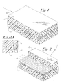
- interface pad 10 comprises a central grid body 11 arranged medially between coating layers 12 and 13. Further, as illustrated in Figure 2, grid 11 is provided with reticulated apertures as at 15-15 which are sized so as to permit ingress or mutual oozing of coatings 12 and 13 until fused together and merged. Further, and as shown in the photomicrograph of Figure 3, following fusion and merger, thermal interface pads of the present invention create and form a continuum through the mesh, thereby eliminating internal thermal interfaces in particularly in the apertures where bridging of the opposed coating occurs.
- FIG. 7 of the drawings a modified interface pad consistent with the present invention is illustrated, having the same features as the modification illustrated in Figures 1-6, with the exception being that the reticulated apertures as at 15A-15A are of a different shape, specifically, a diamond-shaped configuration.
- the various components of Figure 7 are the same as those shown in the embodiment of Figures 1-6, with these components being designated by the same reference numeral together with the suffix "A".
- phase change occurs at temperatures indicated as T1 and T2. More particularly, the materials are selected for the present invention wherein the polymeric matrix at least partially fuses or undergoes a phase change at a temperature lower than that of the liquid metal component. Given the presence of the stabilizing mesh grid, overall stability of the composite is preserved.
- the phase change temperature differential is preferably about 10° C.
- Figure 5 is provided to demonstrate the utilization of the compliant pad of the present invention in connection with a heat generating semiconductor device of conventional configuration. Accordingly, the assembly 10 shown in Figure 5, includes a heat generating semiconductor device or package illustrated at 21 having a heat sink, heat spreader, or other heat dissipating member illustrated at 22. Interposed between the opposed surfaces of semiconductor device 21 and heat dissipating member 22 is a mechanically compliant stabilized thermal interface pad 23 prepared in accordance with the present invention.
- BN or alumina particulate can range in size from up to about 1 micron diameter and up to about 40 microns in cross-sectional thickness. It will be observed that the platelet-like configuration of boron nitride in particular provides a highly desirable and effective combination when wetted with liquid metal, with the effective particle being illustrated in the micrograph of Figure 3. As indicated in Figure 3, the individual laminae flow as a continuum through the openings formed in the grid, with the particulate, wetted with liquid metal, aiding in forming the interface-free continuum through the entire thickness of the pad. Viscosity control is aided by this feature.
- silicone resins may also be utilized as a matrix.
- One such resin is designated "TSE 3053" from GE-Toshiba Silicones, Inc., with these materials being, of course, commercially available. Silicones having viscosities up to about 1000 centistokes may be satisfactorily utilized. The presence of the silane modifies the viscosity slightly, producing an oil composition with slightly lower viscosities.
Landscapes
- Cooling Or The Like Of Semiconductors Or Solid State Devices (AREA)
- Compositions Of Macromolecular Compounds (AREA)
- Laminated Bodies (AREA)
- Adhesives Or Adhesive Processes (AREA)
Abstract
Description
- This application is a continuation-in-part of our co-pending application Serial No. 09/946,879, filed September 5, 2001, entitled "MORPHING FILLERS AND THERMAL INTERFACE MATERIALS"; which application Serial No. 09/946,879 was a continuation-in-part of our prior co-pending application Serial No. 09/690,994, filed October 17, 2000, entitled "METHOD OF PREPARING THERMALLY CONDUCTIVE COMPOUNDS BY LIQUID METAL BRIDGED PARTICLE CLUSTERS", which application Serial No. 09/690,994 is a continuation-in-part application of our parent application Serial No. 09/543,661, filed April 5, 2000, entitled "METHOD OF PREPARING THERMALLY CONDUCTIVE COMPOUNDS BY LIQUID METAL BRIDGED PARTICLE CLUSTERS", now U.S. Patent No. 6,339,120, all of which are assigned to the same assignee as the present application.
- The present invention relates generally to an improved mechanically stabilized thermally conductive interface pad for transferring thermal energy from a heat generating semiconductor device to a heat dissipator such as a heat sink or heat spreader. More specifically, the present invention relates to such an interface which comprises a laminate pad with upper and lower thermally conductive laminae positioned upon and extending through apertures from opposed surfaces of an open mesh grid. In other words, portions of each of the opposed laminae extend through apertures in the stabilizing mesh grid to form a continuum, thus enhancing both mechanical stability and heat transfer efficiency without the creation of additional thermal interfaces.
- The upper and lower laminae preferably comprise formulations of highly thermally conductive polymer compounds such as a polymeric matrix loaded or filled with solid particulate and a liquid or low melting point metal. It will be understood that the term "liquid metal" is intended to refer to a metal or alloy having a melting point which is generally below about 90°C., although some higher melting materials may be included in the definition. The solid particulate typically forms clusters which become coated with the low melting metal and are distributed throughout the matrix. The arrangement of the present invention further provides for extrusion or oozing of portions of the loaded polymer laminae through the grid apertures. Extrusion through these apertures is achieved through application of heat and pressure to a laminae/mesh grid preform which causes the opposed laminae surfaces to merge and create a continuum of the loaded polymer. Accordingly, the continuum creates a mechanically stabilized composite thermally conductive pad which is formed without creation of additional large thermal barriers or interfaces extending along and across the thermal path. As a result, enhanced mechanical stability is achieved without sacrificing valuable properties such as high thermal conductivity and mechanical compliance.
- Liquid metals as well as thermally conductive particulate have each been proposed for incorporation in a polymeric matrix to form thermally conductive interface pads. In the past however, the application of liquid metals for this purpose had not been widely used, primarily because of problems created instability and/or tendency of the liquid metal to oxidize or form alloys and amalgams, thereby altering and modifying the physical properties of the liquid metal component in the pad. In certain arrangements, the liquid metal component would become oxidized, both along the surface as well as in the bulk structure. By way of example, dispersed liquid metal droplets had a tendency to coalesce, a process known as Ostwald ripening, and cause macroscopic separation of the metal from the polymer matrix. In addition the oxidation of the liquid metal was sometimes accelerated upon exposure to warm and/or humid environments; this leading to the formation of brittle oxides which reduced the effectiveness of the thermal properties of the compound. Finally, while some highly thermally conductive components of prior art devices are typically electrically conductive, this property may not always be undesirable. Instability of liquid metals was believed due at least in part to the extremely high surface tension and other chemical and physical properties of the metallic component.
- The present invention relates to thermal interface pads which employ the combination of a liquid metal with a polymer carrier. The liquid metal may either be employed as a filler by itself or preferably as a coating or encapsulant for other fillers dispersed in the polymer carrier. The filler or filler combinations may be pretreated with octyl-triethoxysilane, or other such hydrophobic surfactants, to aid in binding the surface oxide layer of the liquid metal component resulting in enhancement of overall moisture resistance. Alternatively, the silane component is blended in the polymeric matrix. The utilization of a silane such as octyl-triethoxysilane in combination with liquid metal is disclosed in co-pending application Serial No. 09/946,879, the substance of which is incorporated by reference herein.
- The stabilized thermally conductive mechanically compliant laminate pads of the present invention employ a centrally positioned open mesh grid component comprising a grid body with generally reticulated apertures formed therein with the apertures forming passageways or vias through which portions of the loaded polymeric resin may pass. The preparation operations for the stabilized laminate pad include positioning liquid metal/particulate containing laminae on opposed major surfaces of a grid member, and through the application of heat and pressure, causing surface portions of the laminae to flow and merge, so as to create a continuum through apertures in the mesh grid. In addition to enhancement of mechanical stability, the apertures in the intermediate mesh grid accommodate the presence of percolating clusters of liquid metal coated particles as a result of extrusion of these clusters within and through apertures. These advantages are achieved without substantial reducing or compromising desirable thermal or electrical properties while facilitating handling and utility in subsequent end use production and assembly operations.
- In accordance with the present invention, a polymeric matrix is selected, and blended with a quantity of a liquid metal or a liquid metal and particulate combination. The polymeric matrix is preferably selected from the group of compliant compositions including waxes or hot melts. Paraffin waxes, microwaxes, silicone waxes and formulations based on these may be used. Elastomers such as silicone, natural or synthetic rubber, acrylic, polyurethane, etc. may also be used. Glassy materials such as epoxy, phenolics, may also be suitable. The polymeric matrix may be a crosslinked structure or "B-staged", including those which can be crosslinked by the user through through thermal or radiative activation.
- In preparing the blend with a liquid metal a high shear environment is used to break the metal into small particles. Preferably, the liquid metal comprises an alloy of indium and/or gallium, such as a gallium-indium-tin-zinc alloy, a bismuth-indium alloy or a tin-indium-bismuth alloy. Typically a metal that is liquid at room temperature or melting at a relatively low temperature, typically below 120°C and preferably below 60°C.
- If a liquid metal and a particulate filler combination is used, a particulate such as boron nitride, alumina or aluminum nitride is initially dried, and thereafter placed in contact with a liquid metal. In order to appropriately wet the surfaces of the particulate, a mixture of dried particulate and liquid metal is subjected to a mixing operation until the particulate is uniformly coated with the liquid metal. While not absolutely necessary, it is desirable that the particulate be dry before blending with the liquid metal alloy. At this stage of mixing one obtains a thixotropic paste of liquid metal and the powder. One can also visualize the paste as a large percolating cluster.
- Following the coating operation, the coated particulate is mixed with a blend of a liquid polymeric carrier material such as, for example, liquid silicone oil of a desired viscosity, and octyl-triethoxysilane. It is preferred that the liquid metal particulate be incorporated in the polymer blend at or near the packing limit. For liquid metal coated boron nitride, the packing fraction is typically between about 60% and 65% by volume coated particles, balance liquid silicone/octyl-triethoxysilane blend. At these volume fractions, one obtains mechanically compliant compounds that have excellent thermal conductivity due to high packing density. This improves heat transfer due to the creation of a pair of compliant laminae which are thereafter placed in superposed relationship on opposed surfaces of the grid, and subjected to heat and pressure to create a moderate force sufficient to cause opposed surfaces of the laminae to ooze through open zones of the gridwork and merge together as a continuum. Through the application of force, individual extruded portions of the opposed laminae pass into the grid apertures, and fuse or merge to create a stable continuum through the grid.
- Other particulate such as aluminum oxide (alumina), and aluminum nitride have also been found to be useful when properly dried prior to contact with the liquid metal. Other combinations are possible with graphite and similar thermally conductive fillers. For the application of the present invention, the particle size should be such that the average cross-sectional thickness of particles is less than about 50 microns. As with boron nitride, this portion of the working formulation is subjected to a mechanical mixing operation which typically includes a vigorous or high-speed mixing step, with vigorous mixing being continued until a visually smooth paste is formed.
- When incorporated into polymer/silane blend, it has been found that the addition of the liquid metal coated particulate effectively reduces overall viscosity. The mechanism involved in this alteration of viscosity is believed to be due to the reduction of viscous drag at the "effective particle"-polymer /silane interface. Although the liquid metal coating increases the sphericity of the configuration of the particulate, it also contributes to an effective "softness" of the otherwise hard particles. These two factors function in a mutually cooperative fashion so as to reduce both viscosity and modulus of the resulting composite. For this reason, therefore, it is desirable to control the quantity of liquid metal within the blend to the range of between about 10% and 90% by volume liquid metal, balance polymer resin/particulate. This property also facilitates and enhances passage of the formulation through the apertures or vias formed in the mesh grid.
- It has been further found that the liquid metal coated particulate stabilizes and anchors the liquid metal into a three phase composite to prevent gross migration. The three phases are particle-liquid metal-polymer blend. By increasing the viscosity of the metallic phase, the tendency of metal droplets to migrate and coalesce into larger drops that could macroscopically separate and leak from the composite is severely retarded. In order to even further stabilize the structure, the techniques of the present invention are employed in order to enhance mechanical stability. Increased stability is achieved without interposing additional thermal interfaces along and across the entire conductivity path, any one of which increases thermal impedance or resistance. Furthermore, it has been found that the liquid coated particulate provides a Bingham-plastic like character in the resultant composite, this allowing the paste to remain static in the absence of external stress, and yet conform and/or flow easily when subjected to stress. Upon application of heat and pressure, and when liquid metal is incorporated in the range set forth above, the desirable flow characterized as "oozing" of the composite occurs through the apertures formed in the grid.
- Because of the tendency to undergo liquid-to-liquid macroscopic separation, liquid metals do not typically blend well with polymer liquids, including silicones. In accordance with the present invention, however, when particulate, in particular boron nitride, is initially coated with an indium or gallium alloy, the microscopic separation phenomena is reduced, with the liquid metal being supported or retained in coated particulate form. This is believed due to the increased thixotropy of the metal phase. In addition, the coated particulate, when added to the polymer/silane blend, functions effectively to form thermal vias within the composite. In certain cases, the thermal conductivity of the particulate such as boron nitride, may even exceed that of the liquid metal per se, such as, for example, that of a eutectic alloy of indium, gallium, and tin.
- The grid is preferably a thin mesh body fabricated from a highly thermally conductive metal such as, for example, copper or aluminum, although certain non-metallic materials may be used as well. The thin grid preferably has a cross-sectional thickness of between about 0.5 mil and 10 mils, with a thickness of between about 1 and 5 mils having been found to be preferable.
- The grid has an array of reticulated apertures, with the size and density of the apertures creating a grid structure which is between about 10% and 90% open, balance structural. For most purposes, a grid aperture pattern with about 50% or more open is preferred.
- In the event it is found desirable to utilize a non-metallic grid, such a grid may be prepared as a woven or non-woven fabric comprising graphite, carbon or glass fibers. Alternatively, certain other polymer fibers may be employed as well. It is, of course, appropriate to utilize materials of construction which are sufficiently durable for the required application. Any such non-metallic fabric (including non-woven fabrics) would likewise be provided with a reticulated pattern of apertures. It is, of course, always desirable that when non-metallic grids are utilized, the fabric be selected as one having reasonable thermally conductive properties.
- As indicated, grids may be fabricated from a fabric of filaments consisting of polyethylene terephthalate (Dacron), or a polyimide such as nylon, or the like. In connection with non-metallic mesh grids, fabric comprising graphite fibers in a reticulated pattern of 50% open may also be useful. Generally, for non-metallic mesh grids, grids having thicknesses of between about 0.5 and 10 mils with open patterns of between about 10% and 90% are useful.
- Interface pads prepared in accordance with the present invention will typically have an overall thickness of between about .5 mil and 10 mils, with the thickness being based upon the application of polymeric liquid metal bearing coatings to opposed surfaces of the grid. Each of the coatings preferably has a thickness ranging from between about .5 mil and 5 mils.
- Therefore, it is a primary object of the present invention to provide an improved thermal interface pad comprising a polymeric matrix material loaded with a liquid metal or a particulate material coated with a liquid metal.
- It is a further object of the present invention to provide an improved method of preparing a thermally conductive interface pad which creates a thermally conductive bridge between the opposed surfaces of a heat generating semiconductor device and a heat dissipating surface, with the thermally conductive bridge comprising a three phase composite consisting of inorganic particulate, a liquid metal, and a liquid polymer/octyl-triethoxysilane blend.
- Other and further objects of the present invention will become apparent to those skilled in the art upon a study of the following specification, appended claims, and accompanying drawings.
-
- Figure 1 is a perspective view illustrating the individual laminae and stabilizing grid arranged in accordance with the present invention;
- Figure 1A is a fragmentary sectional view on a highly enlarged scale of the individual laminae and stabilizing grid arranged in accordance with the present invention;
- Figure 2 is a view similar to Figure 1, with certain portions of the laminae and grid having been broken away in order to more clearly illustrate the features of the present invention;
- Figure 3 is a reproduction of a photo micrograph of a cross-sectional cut-away of a thermal interface prepared and stabilized in accordance with the present invention;
- Figure 4 is a performance graph of thermal impedance versus temperature for an interface pad fabricated and stabilized in accordance with the present invention;
- Figure 5 is an elevational view, partially in section, of a typical assembly;
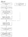
- Figure 6 is a flow chart of the steps involved in a typical operation for preparation of interface pads in accordance with the present invention; and
- Figure 7 is a view similar to Figure 2 and illustrating a modified form of stabilized grid.
- As indicated, the polymer matrix is preferably selected from paraffin wax, microwax, and silicone waxes comprising alkyl silicones. For most purposes waxes having a melting point of about 50-60°C. have been found particularly suited for this application. It is generally desirable to utilize a polymer matrix which undergoes a phase change at a temperature of about 10°C. lower than the phase change temperature of the liquid metal alloy. For certain purposes, soft silicone polymer consisting of a reactive siloxane elastomer, acrylic syrups, epoxy resins , either crosslinked or "B-staged", polyurethane resins are found to be useful.
- One silicone wax utilized in the formulations of the examples is GP-533 (M.P. of 60 °C.) (Genesee Polymer of Flint, MI), with these materials being, of course, commercially available. A microwax employed is that material designated as "M-7332" (M.P. of 55 °C.) available from Moore and Munger of Shelton, CT. Another polymer matrix used is a one-part soft reactive silicone elastomer available from GE Toshiba Silicones of Tokyo, Japan under the trade designation TSE-3053.
- Silanes and other surface active agents including titanates, zirconates and/or assorted surface active agents are preferred to improve rheology and stability of the dispersion, and particularly for creating a hydrophobic barrier. Surface treatments with surface active agents that work well for improving rheology as well as stability of the dispersion, especially against moisture, are alkyl functional silanes, such as for example octyl triethoxy silane (OTES). Another example is methyl trimethoxy (MTMS) silane. These silanes bind to the oxides on the surface of the metal particles, creating a durable hydrophobic barrier. Additionally, these silanes compatibilize the particles with the polymer matrix and reduce particle aggregation.
- While boron nitride is preferred, alumina (aluminum oxide) particulate and/or graphite may be advantageously employed. For example, a particulate of spherical symmetry, with a diameter of 3 microns and a BET surface area of 2m2/g. may be employed. This particulate may be blended with the liquid metal alloys and treated similarly to formulations containing boron nitride to prepare smooth coatings with tixotropic properties. Alumina has a specific gravity of 3.75 and a thermal conductivity of 21 W-m-1-K-1. Alumina may be blended with a selected polymer matrix and treated with octyl-triethoxysilane for the preparation of coatings pursuant to the present invention. For most applications, the volume of the combined particulates/liquid metal alloy will comprise between about 50% and 70% by volume of the interface, balance resin matrix. Also, for conductive particulate of lower density, such as graphite, the particulate/liquid metal alloy component may comprise an amount as low as about 40% of the overall combination when blended with the polymer matrix.
- Alloys which are prepared for use in the present invention having the composition and melting points as follows:
TABLE I Alloy Indium (%) Gallium (%) Bismuth (%( Sn (%) Zinc (%) Melting Point (°C.) 1 51 32.5 16.5 0 60 2 66.3 33.7 0 0 70 3 57 17 0 79 4 52.2 0 46 1.8 108 5 25 61 0 13 1 7 - The following compositions have been prepared utilizing
Alloy 1, with numbers being by weight:TABLE II Formula Matrix Alloy 1 40 Πm Boron Nitride OTES Parts by weight Vol % Parts by weight Vol % Parts by weight Vol % Parts by weight Vol % 1 1001 30 1200 52 100 15 12 3 2 1001 30 1800 67 0 0 10 3 3 1002 32 1200 50 100 15 10 3 1 silicone wax consisting of siloxane backbones with pendant alkyl chains and having a melting point of 60°C. 2 soft silicone polymer consisting of a reactive siloxane elastomer. - Compositions designated
Formulas Alloy 2 forAlloy 1 with comparable results. Other particulates may also be employed using alumina or graphite.TABLE IV Formula Matrix Alloy 1 3 Πm Alumina OTES Parts by weight Vol % Parts by weight Vol % Parts by weight Vol % Parts by weight Vol % 6 1001 30 1200 59 100 8 10 3 TABLE V Formula Matrix Alloy 1 Graphite OTES Parts by weight Vol % Parts by weight Vol % Parts by weight Vol % Parts by weight Vol % 7 1001 33 1200 60 25 4 10 3 -
Formula 1 was applied as two coatings on opposed surfaces of a copper mesh grid having a thickness of 2 mils and a reticulated pattern of diamond apertures 70 mils long and 35 mils wide. This mesh grid had an open area of ∼ 50 %, with reasonable border margins positioned on and along the surfaces. This formulation was applied to opposed surfaces, the coatings each having a thickness of 2 mils. Following application of the coatings to opposed surfaces of the mesh grid, the assembly was pressed under a unit pressure of 1-15 psi at a temperature of approximately 125° F. Thermal performance was excellent, with the thermal conductivity of the compound being
7 W-m-1-K-1 and thermal impedance being less than 0.2 °C-cm2-W-1. In certain formulations and applications,
where the coating is less viscous, it may be desirable to subject the coating to a preliminary cure operation until the "B" stage is reached. -
Formula 2 was applied as two coatings on opposed surfaces of an aluminum mesh grid having a thickness of 1.5 mils and a reticulated pattern ofdiamond apertures 50 mils long and 25 mils wide. This mesh grid had an open area of between ~40 and 50 %, with reasonable but narrow border margins positioned on and along the surfaces. This formulation was applied to opposed surfaces, the coatings each having a thickness of 2.5 mils. Following application of the coatings to opposed surfaces of the mesh grid, the assembly was pressed under a unit pressure of 10-15 psi at a temperature of approximately 125° F. Thermal performance was excellent, with the thermal conductivity of the compound being 3 W-m-1-K-1 and thermal impedance being less than 0.2 °C-cm2-W-1. - Other formulations may be utilized to create thermal interface pads with results substantially similar to those reported in connection with
Formulas Formulas - With attention now being directed to Figures 1 and 2 of the drawings, it will be noted that interface pad generally designated 10 comprises a
central grid body 11 arranged medially between coating layers 12 and 13. Further, as illustrated in Figure 2,grid 11 is provided with reticulated apertures as at 15-15 which are sized so as to permit ingress or mutual oozing ofcoatings - With attention being directed to Figure 7 of the drawings, a modified interface pad consistent with the present invention is illustrated, having the same features as the modification illustrated in Figures 1-6, with the exception being that the reticulated apertures as at 15A-15A are of a different shape, specifically, a diamond-shaped configuration. The various components of Figure 7 are the same as those shown in the embodiment of Figures 1-6, with these components being designated by the same reference numeral together with the suffix "A".
- With attention now being directed to Figure 4 of the drawings, it will be noted that a phase change occurs at temperatures indicated as T1 and T2. More particularly, the materials are selected for the present invention wherein the polymeric matrix at least partially fuses or undergoes a phase change at a temperature lower than that of the liquid metal component. Given the presence of the stabilizing mesh grid, overall stability of the composite is preserved. The phase change temperature differential is preferably about 10° C.
- Figure 5 is provided to demonstrate the utilization of the compliant pad of the present invention in connection with a heat generating semiconductor device of conventional configuration. Accordingly, the
assembly 10 shown in Figure 5, includes a heat generating semiconductor device or package illustrated at 21 having a heat sink, heat spreader, or other heat dissipating member illustrated at 22. Interposed between the opposed surfaces ofsemiconductor device 21 andheat dissipating member 22 is a mechanically compliant stabilizedthermal interface pad 23 prepared in accordance with the present invention. - As previously indicated, BN or alumina particulate can range in size from up to about 1 micron diameter and up to about 40 microns in cross-sectional thickness. It will be observed that the platelet-like configuration of boron nitride in particular provides a highly desirable and effective combination when wetted with liquid metal, with the effective particle being illustrated in the micrograph of Figure 3. As indicated in Figure 3, the individual laminae flow as a continuum through the openings formed in the grid, with the particulate, wetted with liquid metal, aiding in forming the interface-free continuum through the entire thickness of the pad. Viscosity control is aided by this feature.
- Although the siloxanes described above are preferably utilized, silicone resins may also be utilized as a matrix. One such resin is designated "TSE 3053" from GE-Toshiba Silicones, Inc., with these materials being, of course, commercially available. Silicones having viscosities up to about 1000 centistokes may be satisfactorily utilized. The presence of the silane modifies the viscosity slightly, producing an oil composition with slightly lower viscosities.
- It will be appreciated that the above examples are given for purposes of illustration only and are not to be otherwise construed as a limitation upon the scope of the following appended claims.
Claims (6)
- In a stabilized thermally conductive mechanically compliant laminate pad for interposing between opposed surfaces of a heat generating semiconductor device and a heat sink wherein the stabilized thermally conductive mechanically compliant laminate comprises upper and lower laminae on opposed surfaces of a central stabilizing apertured grid and with portions of said laminae extending through apertures in said mesh grid to form a continuum, said stabilized thermally conductive laminate being characterized in that:(a) said upper and lower laminae comprise a mixture of:(1) a polymer matrix;(2) a quantity of low melting indium or gallium containing alloy having a melt point at about 120°C. disbursed within said polymer matrix;(3) a thermally conductive particulate solid disbursed within said polymer matrix;(b) said stabilizing open mesh grid comprising a grid body with an array of generally reticulated apertures formed therein, and with the structure and said grid forming between about 10% and 90% of the area of said mesh grid, balance apertures;(c) each of said reticulated apertures having a cross-sectional dimension greater than about 0.5 mil;(d) said polymer matrix selected from the group consisting of hot melt waxes of paraffin and silicone, elastomers of acrylic, silicone, urethane, and flexible epoxy's, and rigid resins consisting of silicone, urethane, epoxy and phenolic polymers with each polymer matrix having a melting point ranging from between about 40°C. and 120°C.;
- The stabilizing thermally conductive mechanically compliant laminate pad of Claim 1 wherein said polymer matrix is cross linked prior to being interposed between surfaces of heat generating semi-conductor device and a heat sink.
- The stabilizing thermally conductive mechanically compliant laminate pad of Claim 1 wherein said polymer matrix is mountingly interposed between opposed surfaces of a heat generating semi-conductor device and a heat sink while in the B-stage of cure, and thereafter subjected to a cross-linking operation.
- The stabilizing thermally conductive mechanically compliant laminate pad of Claim 1 wherein said alloy has a melt point between about 30°C. and 90°C..
- The stabilizing thermally conductive mechanically compliant laminate pad of Claim 1 wherein said thermally conductive particulate is selected from the group consisting of boron nitride, alumina, and graphite.
- The method of preparing thermally conductive mechanically compliant pads comprising the steps of:(a) preparing a mixture of:(1) a low melting metal selected from the group consisting of gallium and indium alloys, and being in the liquid state at temperatures below 120°C.; and(2) a thermally conductive particulate solid selected from the group consisting of boron nitride, aluminum nitride, and alumina;(b) mechanically blending said mixture to cause the surfaces of said particulate to become wetted with said liquid alloy to form a homogeneous thermally conductive paste wherein said liquid alloy encapsulates individual of said particles comprising said particulate;(c) combining said thermally conductive paste with a quantity of a flowable plastic resin material selected from the group consisting of a silicone wax having a siloxane backbone with pendent alkyl chains, and soft silicone polymers consisting of a reactive elastomer to form a thermally conductive mass, with said thermally conductive mass comprising from between about 10% and 90% by volume of metal coated particulate, balance flowable plastic resin blend;(d) applying said thermally conductive mass to opposed surfaces of a mesh grid having an array of reticulated apertures to form a multi-layer preform grid of between about 10% and 90% open; and(e) subjecting said preform to pressure sufficient to cause said oppositely disposed coatings to pass through said reticulated apertures to merge and form a continuum.
Applications Claiming Priority (2)
| Application Number | Priority Date | Filing Date | Title |
|---|---|---|---|
| US279593 | 2002-10-24 | ||
| US10/279,593 US6984685B2 (en) | 2000-04-05 | 2002-10-24 | Thermal interface pad utilizing low melting metal with retention matrix |
Publications (3)
| Publication Number | Publication Date |
|---|---|
| EP1414063A2 true EP1414063A2 (en) | 2004-04-28 |
| EP1414063A3 EP1414063A3 (en) | 2004-10-13 |
| EP1414063B1 EP1414063B1 (en) | 2007-02-21 |
Family
ID=32069359
Family Applications (1)
| Application Number | Title | Priority Date | Filing Date |
|---|---|---|---|
| EP03255643A Expired - Lifetime EP1414063B1 (en) | 2002-10-24 | 2003-09-10 | Thermal interface pad utilizing low melting metal with retention matrix |
Country Status (6)
| Country | Link |
|---|---|
| US (1) | US6984685B2 (en) |
| EP (1) | EP1414063B1 (en) |
| JP (1) | JP4289949B2 (en) |
| AT (1) | ATE354865T1 (en) |
| CA (1) | CA2438242C (en) |
| DE (1) | DE60311936T2 (en) |
Cited By (11)
| Publication number | Priority date | Publication date | Assignee | Title |
|---|---|---|---|---|
| WO2005096320A3 (en) * | 2004-03-30 | 2006-04-06 | Gen Electric | Thermally conductive compositions and methods of making thereof |
| WO2006023860A3 (en) * | 2004-08-23 | 2006-06-29 | Gen Electric | Thermally conductive composition and method for preparing the same |
| EP1908802A1 (en) * | 2006-10-08 | 2008-04-09 | General Electric Company | Enhanced boron nitride composition and compositions made therewith |
| WO2009035907A3 (en) * | 2007-09-11 | 2009-04-23 | Dow Corning | Thermal interface material, electronic device containing the thermal interface material, and methods for their preparation and use |
| US7976941B2 (en) | 1999-08-31 | 2011-07-12 | Momentive Performance Materials Inc. | Boron nitride particles of spherical geometry and process for making thereof |
| US9550888B2 (en) | 1999-08-31 | 2017-01-24 | Momentive Performance Materials Inc. | Low viscosity filler composition of boron nitride particles of spherical geometry and process |
| US10068830B2 (en) | 2014-02-13 | 2018-09-04 | Honeywell International Inc. | Compressible thermal interface materials |
| US10781349B2 (en) | 2016-03-08 | 2020-09-22 | Honeywell International Inc. | Thermal interface material including crosslinker and multiple fillers |
| US11041103B2 (en) | 2017-09-08 | 2021-06-22 | Honeywell International Inc. | Silicone-free thermal gel |
| US11072706B2 (en) | 2018-02-15 | 2021-07-27 | Honeywell International Inc. | Gel-type thermal interface material |
| US11373921B2 (en) | 2019-04-23 | 2022-06-28 | Honeywell International Inc. | Gel-type thermal interface material with low pre-curing viscosity and elastic properties post-curing |
Families Citing this family (34)
| Publication number | Priority date | Publication date | Assignee | Title |
|---|---|---|---|---|
| JP4551074B2 (en) * | 2003-10-07 | 2010-09-22 | 信越化学工業株式会社 | Curable organopolysiloxane composition and semiconductor device |
| TWI259567B (en) * | 2003-12-16 | 2006-08-01 | Fuji Polymer Ind | Thermally conductive composite sheet |
| US7219713B2 (en) * | 2005-01-18 | 2007-05-22 | International Business Machines Corporation | Heterogeneous thermal interface for cooling |
| JP4634891B2 (en) * | 2005-08-18 | 2011-02-16 | 信越化学工業株式会社 | Thermally conductive silicone grease composition and cured product thereof |
| JP4860229B2 (en) * | 2005-10-11 | 2012-01-25 | モメンティブ・パフォーマンス・マテリアルズ・ジャパン合同会社 | Thermally conductive grease composition |
| US20070137836A1 (en) * | 2005-12-19 | 2007-06-21 | Qnx Cooling Systems, Inc. | Heat transfer system |
| US20070179232A1 (en) * | 2006-01-30 | 2007-08-02 | National Starch And Chemical Investment Holding Corporation | Thermal Interface Material |
| US7863639B2 (en) * | 2006-04-12 | 2011-01-04 | Semileds Optoelectronics Co. Ltd. | Light-emitting diode lamp with low thermal resistance |
| US8373195B2 (en) | 2006-04-12 | 2013-02-12 | SemiLEDs Optoelectronics Co., Ltd. | Light-emitting diode lamp with low thermal resistance |
| US20080068803A1 (en) * | 2006-09-18 | 2008-03-20 | Shyh-Ming Chen | Heat dissipating device holder structure with a thin film thermal conducting medium coating |
| EP2188834A4 (en) * | 2007-09-11 | 2014-03-19 | Dow Corning | COMPOSITE, THERMAL INTERFACE MATERIAL CONTAINING THE COMPOSITE AND METHODS FOR THE PREPARATION AND USE THEREOF |
| US7760507B2 (en) * | 2007-12-26 | 2010-07-20 | The Bergquist Company | Thermally and electrically conductive interconnect structures |
| US7742307B2 (en) * | 2008-01-17 | 2010-06-22 | Raytheon Company | High performance power device |
| US20090208722A1 (en) * | 2008-02-18 | 2009-08-20 | John Francis Timmerman | Oriented Members for Thermally Conductive Interface Structures |
| JP4913874B2 (en) * | 2010-01-18 | 2012-04-11 | 信越化学工業株式会社 | Curable organopolysiloxane composition and semiconductor device |
| JP5542280B2 (en) * | 2010-11-24 | 2014-07-09 | トヨタ自動車株式会社 | Thermal grease composition |
| US20120248092A1 (en) * | 2011-03-30 | 2012-10-04 | Palo Alto Research Center Incorporated | Low temperature thermistor process |
| JP5640945B2 (en) | 2011-10-11 | 2014-12-17 | 信越化学工業株式会社 | Curable organopolysiloxane composition and semiconductor device |
| JP2013115083A (en) * | 2011-11-25 | 2013-06-10 | Fujitsu Semiconductor Ltd | Semiconductor device and method of manufacturing the same |
| KR102100925B1 (en) * | 2013-03-22 | 2020-04-14 | 삼성전자주식회사 | Substrate assembly, method of forming the substrate assembly, and electronic device comprising the same |
| KR20160094385A (en) | 2013-12-05 | 2016-08-09 | 허니웰 인터내셔날 인코포레이티드 | STANNOUS METHANSULFONATE SOLUTION WITH ADJUSTED pH |
| US10155894B2 (en) | 2014-07-07 | 2018-12-18 | Honeywell International Inc. | Thermal interface material with ion scavenger |
| CN107250317A (en) | 2014-12-05 | 2017-10-13 | 霍尼韦尔国际公司 | High performance thermal interface material with low thermal resistance |
| WO2017044712A1 (en) | 2015-09-11 | 2017-03-16 | Laird Technologies, Inc. | Devices for absorbing energy from electronic components |
| US10312177B2 (en) | 2015-11-17 | 2019-06-04 | Honeywell International Inc. | Thermal interface materials including a coloring agent |
| US10720261B2 (en) * | 2016-02-02 | 2020-07-21 | Carnegie Mellon University, A Pennsylvania Non-Profit Corporation | Polymer composite with liquid phase metal inclusions |
| US10501671B2 (en) | 2016-07-26 | 2019-12-10 | Honeywell International Inc. | Gel-type thermal interface material |
| US10327332B2 (en) * | 2016-10-06 | 2019-06-18 | Microsoft Technology Licensing, Llc | Connecting a flexible circuit to other structures |
| US10428256B2 (en) | 2017-10-23 | 2019-10-01 | Honeywell International Inc. | Releasable thermal gel |
| US10777483B1 (en) * | 2020-02-28 | 2020-09-15 | Arieca Inc. | Method, apparatus, and assembly for thermally connecting layers |
| CN116408453B (en) * | 2021-12-31 | 2026-01-16 | 天之棋(上海)材料科技有限公司 | Composite heat conduction material of copper foil substrate |
| CN115873564A (en) * | 2022-12-13 | 2023-03-31 | 空间液态金属科技发展(江苏)有限公司 | A kind of liquid metal heat conduction sheet and preparation method thereof |
| CN116606636A (en) * | 2023-05-22 | 2023-08-18 | 桂林电子科技大学 | Composite thermal interface material based on liquid metal enhanced heat transfer and preparation method thereof |
| WO2026025014A1 (en) * | 2024-07-25 | 2026-01-29 | Henkel Ag & Co. Kgaa | Low melting alloy thermal interface materials |
Family Cites Families (25)
| Publication number | Priority date | Publication date | Assignee | Title |
|---|---|---|---|---|
| US3226608A (en) | 1959-06-24 | 1965-12-28 | Gen Electric | Liquid metal electrical connection |
| US3248615A (en) | 1963-05-13 | 1966-04-26 | Bbc Brown Boveri & Cie | Semiconductor device with liquidized solder layer for compensation of expansion stresses |
| CS182611B1 (en) | 1976-03-18 | 1978-04-28 | Pavel Reichel | Power semiconducting element |
| US4147669A (en) | 1977-03-28 | 1979-04-03 | Rockwell International Corporation | Conductive adhesive for providing electrical and thermal conductivity |
| US4233103A (en) | 1978-12-20 | 1980-11-11 | The United States Of America As Represented By The Secretary Of The Air Force | High temperature-resistant conductive adhesive and method employing same |
| US4323914A (en) | 1979-02-01 | 1982-04-06 | International Business Machines Corporation | Heat transfer structure for integrated circuit package |
| US4254431A (en) | 1979-06-20 | 1981-03-03 | International Business Machines Corporation | Restorable backbond for LSI chips using liquid metal coated dendrites |
| JPS57107501A (en) | 1980-12-25 | 1982-07-05 | Sony Corp | Conduction material |
| JPH0770650B2 (en) | 1986-10-20 | 1995-07-31 | 富士通株式会社 | Semiconductor device cooling method |
| US5053195A (en) | 1989-07-19 | 1991-10-01 | Microelectronics And Computer Technology Corp. | Bonding amalgam and method of making |
| US5225157A (en) | 1989-07-19 | 1993-07-06 | Microelectronics And Computer Technology Corporation | Amalgam composition for room temperature bonding |
| US5173256A (en) | 1989-08-03 | 1992-12-22 | International Business Machines Corporation | Liquid metal matrix thermal paste |
| US5198189A (en) | 1989-08-03 | 1993-03-30 | International Business Machines Corporation | Liquid metal matrix thermal paste |
| US5056706A (en) | 1989-11-20 | 1991-10-15 | Microelectronics And Computer Technology Corporation | Liquid metal paste for thermal and electrical connections |
| US5170930A (en) | 1991-11-14 | 1992-12-15 | Microelectronics And Computer Technology Corporation | Liquid metal paste for thermal and electrical connections |
| US5445308A (en) | 1993-03-29 | 1995-08-29 | Nelson; Richard D. | Thermally conductive connection with matrix material and randomly dispersed filler containing liquid metal |
| US5328087A (en) | 1993-03-29 | 1994-07-12 | Microelectronics And Computer Technology Corporation | Thermally and electrically conductive adhesive material and method of bonding with same |
| JP3462308B2 (en) * | 1995-06-16 | 2003-11-05 | 住友特殊金属株式会社 | Manufacturing method of heat conductive composite material |
| US5950066A (en) | 1996-06-14 | 1999-09-07 | The Bergquist Company | Semisolid thermal interface with low flow resistance |
| US5919329A (en) | 1997-10-14 | 1999-07-06 | Gore Enterprise Holdings, Inc. | Method for assembling an integrated circuit chip package having at least one semiconductor device |
| US6399209B1 (en) | 1999-04-16 | 2002-06-04 | The Bergquist Company | Integrated release films for phase-change interfaces |
| US6165612A (en) * | 1999-05-14 | 2000-12-26 | The Bergquist Company | Thermally conductive interface layers |
| US6339120B1 (en) * | 2000-04-05 | 2002-01-15 | The Bergquist Company | Method of preparing thermally conductive compounds by liquid metal bridged particle clusters |
| EP1143511B1 (en) | 2000-04-05 | 2008-01-02 | The Bergquist Company | Method of preparing thermally conductive compounds by liquid metal bridged particle clusters |
| US6797758B2 (en) * | 2000-04-05 | 2004-09-28 | The Bergquist Company | Morphing fillers and thermal interface materials |
-
2002
- 2002-10-24 US US10/279,593 patent/US6984685B2/en not_active Expired - Lifetime
-
2003
- 2003-08-25 JP JP2003299900A patent/JP4289949B2/en not_active Expired - Fee Related
- 2003-08-26 CA CA002438242A patent/CA2438242C/en not_active Expired - Fee Related
- 2003-09-10 AT AT03255643T patent/ATE354865T1/en not_active IP Right Cessation
- 2003-09-10 DE DE60311936T patent/DE60311936T2/en not_active Expired - Lifetime
- 2003-09-10 EP EP03255643A patent/EP1414063B1/en not_active Expired - Lifetime
Cited By (13)
| Publication number | Priority date | Publication date | Assignee | Title |
|---|---|---|---|---|
| US9079801B2 (en) | 1999-08-31 | 2015-07-14 | Momentive Performance Materials Inc. | Boron nitride particles of spherical geometry and process of making |
| US7976941B2 (en) | 1999-08-31 | 2011-07-12 | Momentive Performance Materials Inc. | Boron nitride particles of spherical geometry and process for making thereof |
| US9550888B2 (en) | 1999-08-31 | 2017-01-24 | Momentive Performance Materials Inc. | Low viscosity filler composition of boron nitride particles of spherical geometry and process |
| WO2005096320A3 (en) * | 2004-03-30 | 2006-04-06 | Gen Electric | Thermally conductive compositions and methods of making thereof |
| WO2006023860A3 (en) * | 2004-08-23 | 2006-06-29 | Gen Electric | Thermally conductive composition and method for preparing the same |
| EP1908802A1 (en) * | 2006-10-08 | 2008-04-09 | General Electric Company | Enhanced boron nitride composition and compositions made therewith |
| WO2009035907A3 (en) * | 2007-09-11 | 2009-04-23 | Dow Corning | Thermal interface material, electronic device containing the thermal interface material, and methods for their preparation and use |
| US8334592B2 (en) | 2007-09-11 | 2012-12-18 | Dow Corning Corporation | Thermal interface material, electronic device containing the thermal interface material, and methods for their preparation and use |
| US10068830B2 (en) | 2014-02-13 | 2018-09-04 | Honeywell International Inc. | Compressible thermal interface materials |
| US10781349B2 (en) | 2016-03-08 | 2020-09-22 | Honeywell International Inc. | Thermal interface material including crosslinker and multiple fillers |
| US11041103B2 (en) | 2017-09-08 | 2021-06-22 | Honeywell International Inc. | Silicone-free thermal gel |
| US11072706B2 (en) | 2018-02-15 | 2021-07-27 | Honeywell International Inc. | Gel-type thermal interface material |
| US11373921B2 (en) | 2019-04-23 | 2022-06-28 | Honeywell International Inc. | Gel-type thermal interface material with low pre-curing viscosity and elastic properties post-curing |
Also Published As
| Publication number | Publication date |
|---|---|
| JP2004146795A (en) | 2004-05-20 |
| EP1414063B1 (en) | 2007-02-21 |
| DE60311936D1 (en) | 2007-04-05 |
| DE60311936T2 (en) | 2007-10-31 |
| CA2438242A1 (en) | 2004-04-24 |
| CA2438242C (en) | 2008-07-08 |
| JP4289949B2 (en) | 2009-07-01 |
| ATE354865T1 (en) | 2007-03-15 |
| EP1414063A3 (en) | 2004-10-13 |
| US20030187116A1 (en) | 2003-10-02 |
| US6984685B2 (en) | 2006-01-10 |
Similar Documents
| Publication | Publication Date | Title |
|---|---|---|
| EP1414063B1 (en) | Thermal interface pad utilizing low melting metal with retention matrix | |
| EP1143512B1 (en) | Method of preparing thermally conductive compounds by liquid metal bridged particle clusters | |
| CA2401299C (en) | Morphing fillers and thermal interface materials | |
| US7960019B2 (en) | Phase change material containing fusible particles as thermally conductive filler | |
| CN100477182C (en) | phase change thermal interface material using polyester resin and clay filler | |
| EP1797155B1 (en) | Thermally conductive composition and method for preparing the same | |
| EP1143511A2 (en) | Method of preparing thermally conductive compounds by liquid metal bridged particle clusters | |
| WO2005031864A1 (en) | Thermal interface material with aligned carbon nanotubes | |
| CA2719639A1 (en) | Thermally enhanced electrically insulative adhesive paste | |
| JP2002121292A (en) | Method for producing heat conductive compound by using liquid metal-crosslinked particle cluster | |
| TWI464749B (en) | Conductive composition | |
| WO2006039291A1 (en) | Thermally conductive composite and uses for microelectronic packaging | |
| TW200408666A (en) | Thermal interface pad utilizing low melting metal with retention matrix | |
| WO2024154455A1 (en) | Sheet-form heat dissipation member | |
| US20070256783A1 (en) | Thermally enhanced adhesive paste | |
| EP4544589A1 (en) | Thermal interface materials with soft filler dispersions | |
| EP1794224A1 (en) | Thermally conductive composite and uses for microelectronic packaging |
Legal Events
| Date | Code | Title | Description |
|---|---|---|---|
| PUAI | Public reference made under article 153(3) epc to a published international application that has entered the european phase |
Free format text: ORIGINAL CODE: 0009012 |
|
| AK | Designated contracting states |
Kind code of ref document: A2 Designated state(s): AT BE BG CH CY CZ DE DK EE ES FI FR GB GR HU IE IT LI LU MC NL PT RO SE SI SK TR |
|
| AX | Request for extension of the european patent |
Extension state: AL LT LV MK |
|
| PUAL | Search report despatched |
Free format text: ORIGINAL CODE: 0009013 |
|
| AK | Designated contracting states |
Kind code of ref document: A3 Designated state(s): AT BE BG CH CY CZ DE DK EE ES FI FR GB GR HU IE IT LI LU MC NL PT RO SE SI SK TR |
|
| AX | Request for extension of the european patent |
Extension state: AL LT LV MK |
|
| RIC1 | Information provided on ipc code assigned before grant |
Ipc: 7H 01L 23/433 B Ipc: 7H 01L 23/373 A |
|
| 17P | Request for examination filed |
Effective date: 20050225 |
|
| 17Q | First examination report despatched |
Effective date: 20050421 |
|
| AKX | Designation fees paid |
Designated state(s): AT BE BG CH CY CZ DE DK EE ES FI FR GB GR HU IE IT LI LU MC NL PT RO SE SI SK TR |
|
| GRAP | Despatch of communication of intention to grant a patent |
Free format text: ORIGINAL CODE: EPIDOSNIGR1 |
|
| GRAS | Grant fee paid |
Free format text: ORIGINAL CODE: EPIDOSNIGR3 |
|
| GRAA | (expected) grant |
Free format text: ORIGINAL CODE: 0009210 |
|
| AK | Designated contracting states |
Kind code of ref document: B1 Designated state(s): AT BE BG CH CY CZ DE DK EE ES FI FR GB GR HU IE IT LI LU MC NL PT RO SE SI SK TR |
|
| PG25 | Lapsed in a contracting state [announced via postgrant information from national office to epo] |
Ref country code: SI Free format text: LAPSE BECAUSE OF FAILURE TO SUBMIT A TRANSLATION OF THE DESCRIPTION OR TO PAY THE FEE WITHIN THE PRESCRIBED TIME-LIMIT Effective date: 20070221 Ref country code: CH Free format text: LAPSE BECAUSE OF FAILURE TO SUBMIT A TRANSLATION OF THE DESCRIPTION OR TO PAY THE FEE WITHIN THE PRESCRIBED TIME-LIMIT Effective date: 20070221 Ref country code: NL Free format text: LAPSE BECAUSE OF FAILURE TO SUBMIT A TRANSLATION OF THE DESCRIPTION OR TO PAY THE FEE WITHIN THE PRESCRIBED TIME-LIMIT Effective date: 20070221 Ref country code: FI Free format text: LAPSE BECAUSE OF FAILURE TO SUBMIT A TRANSLATION OF THE DESCRIPTION OR TO PAY THE FEE WITHIN THE PRESCRIBED TIME-LIMIT Effective date: 20070221 Ref country code: DK Free format text: LAPSE BECAUSE OF FAILURE TO SUBMIT A TRANSLATION OF THE DESCRIPTION OR TO PAY THE FEE WITHIN THE PRESCRIBED TIME-LIMIT Effective date: 20070221 Ref country code: LI Free format text: LAPSE BECAUSE OF FAILURE TO SUBMIT A TRANSLATION OF THE DESCRIPTION OR TO PAY THE FEE WITHIN THE PRESCRIBED TIME-LIMIT Effective date: 20070221 Ref country code: BE Free format text: LAPSE BECAUSE OF FAILURE TO SUBMIT A TRANSLATION OF THE DESCRIPTION OR TO PAY THE FEE WITHIN THE PRESCRIBED TIME-LIMIT Effective date: 20070221 Ref country code: AT Free format text: LAPSE BECAUSE OF FAILURE TO SUBMIT A TRANSLATION OF THE DESCRIPTION OR TO PAY THE FEE WITHIN THE PRESCRIBED TIME-LIMIT Effective date: 20070221 |
|
| REG | Reference to a national code |
Ref country code: GB Ref legal event code: FG4D |
|
| REG | Reference to a national code |
Ref country code: CH Ref legal event code: EP |
|
| REF | Corresponds to: |
Ref document number: 60311936 Country of ref document: DE Date of ref document: 20070405 Kind code of ref document: P |
|
| REG | Reference to a national code |
Ref country code: IE Ref legal event code: FG4D |
|
| PG25 | Lapsed in a contracting state [announced via postgrant information from national office to epo] |
Ref country code: SE Free format text: LAPSE BECAUSE OF FAILURE TO SUBMIT A TRANSLATION OF THE DESCRIPTION OR TO PAY THE FEE WITHIN THE PRESCRIBED TIME-LIMIT Effective date: 20070521 |
|
| PG25 | Lapsed in a contracting state [announced via postgrant information from national office to epo] |
Ref country code: BG Free format text: LAPSE BECAUSE OF EXPIRATION OF PROTECTION Effective date: 20070522 |
|
| PG25 | Lapsed in a contracting state [announced via postgrant information from national office to epo] |
Ref country code: ES Free format text: LAPSE BECAUSE OF FAILURE TO SUBMIT A TRANSLATION OF THE DESCRIPTION OR TO PAY THE FEE WITHIN THE PRESCRIBED TIME-LIMIT Effective date: 20070601 |
|
| PG25 | Lapsed in a contracting state [announced via postgrant information from national office to epo] |
Ref country code: PT Free format text: LAPSE BECAUSE OF FAILURE TO SUBMIT A TRANSLATION OF THE DESCRIPTION OR TO PAY THE FEE WITHIN THE PRESCRIBED TIME-LIMIT Effective date: 20070723 |
|
| NLV1 | Nl: lapsed or annulled due to failure to fulfill the requirements of art. 29p and 29m of the patents act | ||
| ET | Fr: translation filed | ||
| REG | Reference to a national code |
Ref country code: CH Ref legal event code: PL |
|
| PG25 | Lapsed in a contracting state [announced via postgrant information from national office to epo] |
Ref country code: SK Free format text: LAPSE BECAUSE OF FAILURE TO SUBMIT A TRANSLATION OF THE DESCRIPTION OR TO PAY THE FEE WITHIN THE PRESCRIBED TIME-LIMIT Effective date: 20070221 |
|
| PLBE | No opposition filed within time limit |
Free format text: ORIGINAL CODE: 0009261 |
|
| STAA | Information on the status of an ep patent application or granted ep patent |
Free format text: STATUS: NO OPPOSITION FILED WITHIN TIME LIMIT |
|
| PG25 | Lapsed in a contracting state [announced via postgrant information from national office to epo] |
Ref country code: RO Free format text: LAPSE BECAUSE OF FAILURE TO SUBMIT A TRANSLATION OF THE DESCRIPTION OR TO PAY THE FEE WITHIN THE PRESCRIBED TIME-LIMIT Effective date: 20070221 Ref country code: CZ Free format text: LAPSE BECAUSE OF FAILURE TO SUBMIT A TRANSLATION OF THE DESCRIPTION OR TO PAY THE FEE WITHIN THE PRESCRIBED TIME-LIMIT Effective date: 20070221 |
|
| 26N | No opposition filed |
Effective date: 20071122 |
|
| PG25 | Lapsed in a contracting state [announced via postgrant information from national office to epo] |
Ref country code: GR Free format text: LAPSE BECAUSE OF FAILURE TO SUBMIT A TRANSLATION OF THE DESCRIPTION OR TO PAY THE FEE WITHIN THE PRESCRIBED TIME-LIMIT Effective date: 20070522 Ref country code: IT Free format text: LAPSE BECAUSE OF FAILURE TO SUBMIT A TRANSLATION OF THE DESCRIPTION OR TO PAY THE FEE WITHIN THE PRESCRIBED TIME-LIMIT Effective date: 20070221 Ref country code: MC Free format text: LAPSE BECAUSE OF NON-PAYMENT OF DUE FEES Effective date: 20070930 |
|
| PGFP | Annual fee paid to national office [announced via postgrant information from national office to epo] |
Ref country code: IE Payment date: 20080128 Year of fee payment: 5 |
|
| PG25 | Lapsed in a contracting state [announced via postgrant information from national office to epo] |
Ref country code: EE Free format text: LAPSE BECAUSE OF FAILURE TO SUBMIT A TRANSLATION OF THE DESCRIPTION OR TO PAY THE FEE WITHIN THE PRESCRIBED TIME-LIMIT Effective date: 20070221 |
|
| PG25 | Lapsed in a contracting state [announced via postgrant information from national office to epo] |
Ref country code: CY Free format text: LAPSE BECAUSE OF FAILURE TO SUBMIT A TRANSLATION OF THE DESCRIPTION OR TO PAY THE FEE WITHIN THE PRESCRIBED TIME-LIMIT Effective date: 20070221 Ref country code: IE Free format text: LAPSE BECAUSE OF NON-PAYMENT OF DUE FEES Effective date: 20080910 |
|
| PG25 | Lapsed in a contracting state [announced via postgrant information from national office to epo] |
Ref country code: LU Free format text: LAPSE BECAUSE OF NON-PAYMENT OF DUE FEES Effective date: 20070910 |
|
| PG25 | Lapsed in a contracting state [announced via postgrant information from national office to epo] |
Ref country code: TR Free format text: LAPSE BECAUSE OF FAILURE TO SUBMIT A TRANSLATION OF THE DESCRIPTION OR TO PAY THE FEE WITHIN THE PRESCRIBED TIME-LIMIT Effective date: 20070221 Ref country code: HU Free format text: LAPSE BECAUSE OF FAILURE TO SUBMIT A TRANSLATION OF THE DESCRIPTION OR TO PAY THE FEE WITHIN THE PRESCRIBED TIME-LIMIT Effective date: 20070822 |
|
| REG | Reference to a national code |
Ref country code: FR Ref legal event code: PLFP Year of fee payment: 14 |
|
| REG | Reference to a national code |
Ref country code: FR Ref legal event code: PLFP Year of fee payment: 15 |
|
| REG | Reference to a national code |
Ref country code: FR Ref legal event code: PLFP Year of fee payment: 16 |
|
| PGFP | Annual fee paid to national office [announced via postgrant information from national office to epo] |
Ref country code: DE Payment date: 20180920 Year of fee payment: 16 Ref country code: FR Payment date: 20180924 Year of fee payment: 16 |
|
| PGFP | Annual fee paid to national office [announced via postgrant information from national office to epo] |
Ref country code: GB Payment date: 20180919 Year of fee payment: 16 |
|
| REG | Reference to a national code |
Ref country code: DE Ref legal event code: R119 Ref document number: 60311936 Country of ref document: DE |
|
| PG25 | Lapsed in a contracting state [announced via postgrant information from national office to epo] |
Ref country code: DE Free format text: LAPSE BECAUSE OF NON-PAYMENT OF DUE FEES Effective date: 20200401 |
|
| GBPC | Gb: european patent ceased through non-payment of renewal fee |
Effective date: 20190910 |
|
| PG25 | Lapsed in a contracting state [announced via postgrant information from national office to epo] |
Ref country code: GB Free format text: LAPSE BECAUSE OF NON-PAYMENT OF DUE FEES Effective date: 20190910 Ref country code: FR Free format text: LAPSE BECAUSE OF NON-PAYMENT OF DUE FEES Effective date: 20190930 |