EP1413878A1 - Nonuniform-density sample analyzing method, device,and system - Google Patents
Nonuniform-density sample analyzing method, device,and system Download PDFInfo
- Publication number
- EP1413878A1 EP1413878A1 EP02738736A EP02738736A EP1413878A1 EP 1413878 A1 EP1413878 A1 EP 1413878A1 EP 02738736 A EP02738736 A EP 02738736A EP 02738736 A EP02738736 A EP 02738736A EP 1413878 A1 EP1413878 A1 EP 1413878A1
- Authority
- EP
- European Patent Office
- Prior art keywords
- ray scattering
- scattering curve
- uniform density
- plane
- density sample
- Prior art date
- Legal status (The legal status is an assumption and is not a legal conclusion. Google has not performed a legal analysis and makes no representation as to the accuracy of the status listed.)
- Granted
Links
- 238000000034 method Methods 0.000 title claims abstract description 26
- 238000000333 X-ray scattering Methods 0.000 claims abstract description 86
- 238000005259 measurement Methods 0.000 claims abstract description 33
- 238000004088 simulation Methods 0.000 claims description 7
- 239000002245 particle Substances 0.000 description 11
- 238000004458 analytical method Methods 0.000 description 6
- 230000000149 penetrating effect Effects 0.000 description 6
- 238000010586 diagram Methods 0.000 description 3
- 239000010408 film Substances 0.000 description 3
- 238000002310 reflectometry Methods 0.000 description 2
- 239000010409 thin film Substances 0.000 description 2
- YBJHBAHKTGYVGT-ZKWXMUAHSA-N (+)-Biotin Chemical compound N1C(=O)N[C@@H]2[C@H](CCCCC(=O)O)SC[C@@H]21 YBJHBAHKTGYVGT-ZKWXMUAHSA-N 0.000 description 1
- 230000008901 benefit Effects 0.000 description 1
- 238000004364 calculation method Methods 0.000 description 1
- 230000008859 change Effects 0.000 description 1
- 239000013078 crystal Substances 0.000 description 1
- 239000010419 fine particle Substances 0.000 description 1
- 230000006872 improvement Effects 0.000 description 1
- 238000012986 modification Methods 0.000 description 1
- 230000004048 modification Effects 0.000 description 1
- 239000011148 porous material Substances 0.000 description 1
- 238000012916 structural analysis Methods 0.000 description 1
- FEPMHVLSLDOMQC-UHFFFAOYSA-N virginiamycin-S1 Natural products CC1OC(=O)C(C=2C=CC=CC=2)NC(=O)C2CC(=O)CCN2C(=O)C(CC=2C=CC=CC=2)N(C)C(=O)C2CCCN2C(=O)C(CC)NC(=O)C1NC(=O)C1=NC=CC=C1O FEPMHVLSLDOMQC-UHFFFAOYSA-N 0.000 description 1
Images






Classifications
-
- G—PHYSICS
- G01—MEASURING; TESTING
- G01N—INVESTIGATING OR ANALYSING MATERIALS BY DETERMINING THEIR CHEMICAL OR PHYSICAL PROPERTIES
- G01N23/00—Investigating or analysing materials by the use of wave or particle radiation, e.g. X-rays or neutrons, not covered by groups G01N3/00 – G01N17/00, G01N21/00 or G01N22/00
- G01N23/20—Investigating or analysing materials by the use of wave or particle radiation, e.g. X-rays or neutrons, not covered by groups G01N3/00 – G01N17/00, G01N21/00 or G01N22/00 by using diffraction of the radiation by the materials, e.g. for investigating crystal structure; by using scattering of the radiation by the materials, e.g. for investigating non-crystalline materials; by using reflection of the radiation by the materials
-
- G—PHYSICS
- G01—MEASURING; TESTING
- G01N—INVESTIGATING OR ANALYSING MATERIALS BY DETERMINING THEIR CHEMICAL OR PHYSICAL PROPERTIES
- G01N23/00—Investigating or analysing materials by the use of wave or particle radiation, e.g. X-rays or neutrons, not covered by groups G01N3/00 – G01N17/00, G01N21/00 or G01N22/00
- G01N23/20—Investigating or analysing materials by the use of wave or particle radiation, e.g. X-rays or neutrons, not covered by groups G01N3/00 – G01N17/00, G01N21/00 or G01N22/00 by using diffraction of the radiation by the materials, e.g. for investigating crystal structure; by using scattering of the radiation by the materials, e.g. for investigating non-crystalline materials; by using reflection of the radiation by the materials
- G01N23/201—Investigating or analysing materials by the use of wave or particle radiation, e.g. X-rays or neutrons, not covered by groups G01N3/00 – G01N17/00, G01N21/00 or G01N22/00 by using diffraction of the radiation by the materials, e.g. for investigating crystal structure; by using scattering of the radiation by the materials, e.g. for investigating non-crystalline materials; by using reflection of the radiation by the materials by measuring small-angle scattering
-
- G—PHYSICS
- G01—MEASURING; TESTING
- G01N—INVESTIGATING OR ANALYSING MATERIALS BY DETERMINING THEIR CHEMICAL OR PHYSICAL PROPERTIES
- G01N23/00—Investigating or analysing materials by the use of wave or particle radiation, e.g. X-rays or neutrons, not covered by groups G01N3/00 – G01N17/00, G01N21/00 or G01N22/00
- G01N23/20—Investigating or analysing materials by the use of wave or particle radiation, e.g. X-rays or neutrons, not covered by groups G01N3/00 – G01N17/00, G01N21/00 or G01N22/00 by using diffraction of the radiation by the materials, e.g. for investigating crystal structure; by using scattering of the radiation by the materials, e.g. for investigating non-crystalline materials; by using reflection of the radiation by the materials
- G01N23/203—Measuring back scattering
-
- G—PHYSICS
- G01—MEASURING; TESTING
- G01N—INVESTIGATING OR ANALYSING MATERIALS BY DETERMINING THEIR CHEMICAL OR PHYSICAL PROPERTIES
- G01N23/00—Investigating or analysing materials by the use of wave or particle radiation, e.g. X-rays or neutrons, not covered by groups G01N3/00 – G01N17/00, G01N21/00 or G01N22/00
- G01N23/20—Investigating or analysing materials by the use of wave or particle radiation, e.g. X-rays or neutrons, not covered by groups G01N3/00 – G01N17/00, G01N21/00 or G01N22/00 by using diffraction of the radiation by the materials, e.g. for investigating crystal structure; by using scattering of the radiation by the materials, e.g. for investigating non-crystalline materials; by using reflection of the radiation by the materials
- G01N23/207—Diffractometry using detectors, e.g. using a probe in a central position and one or more displaceable detectors in circumferential positions
Definitions
- the present invention relates to a method, device and system for analyzing a non-uniform density sample, and more particularly to a novel non-uniform density sample analyzing method, non-uniform density sample analyzing device and non-uniform density sample analyzing system capable of simply, accurately analyzing an in-plane direction distribution state of particle-like matter in the non-uniform density sample.
- a method for analyzing a particle diameter distribution in a non-uniform density sample such as a porous film by using an X-ray has been newly proposed by the inventors of the present invention (see Japanese Patent Application No. 2001-088656).
- a diffuse scattering intensity of the X-ray is measured and the particle diameter distribution is analyzed based on the measured intensity, thereby realizing an excellent analyzing ability.
- a non-anisotropic non-uniform density sample is a sample in which particle-like matter such as fine particle and pore has a random distribution as shown in, for example, Fig. 1(a).
- the anisotropic non-uniform density sample is a sample in which the distribution of particle-like matter has some regularity or directivity in an in-plane direction.
- the particle-like matter is distributed in the in-plane direction with the regularity in which clusters each having two pentagons connected to each other are formed.
- the present invention has been achieved in light of these situations and it is an object of the present invention to provide a novel non-uniform density sample analyzing method as well as a non-uniform density sample analyzing device and a non-uniform density sample analyzing system capable of simply and highly accurately analyzing the distribution state of the particle-like matter in the anisotropic non-uniform density sample in the in-plane direction.
- the present invention provides a non-uniform density sample analyzing method comprising the steps of: calculating a simulated X-ray scattering curve under the same condition as a measurement condition of an actually measured X-ray scattering curve by using a scattering function which represents an X-ray scattering curve according to a fitting parameter which indicates distribution sate of particle-like matter; and carrying out fitting between the simulated X-ray scattering curve and the actually measured X-ray scattering curve while changing the fitting parameter, wherein the value of the fitting parameter when the simulated X-ray scattering curve agrees with the actually measured X-ray scattering curve serves to indicate the distribution state of the particle-like matter in a non-uniform density sample, thereby analyzing the distribution state of the particle-like matter in the non-uniform density sample, wherein the actually measured X-ray scattering curve is an in-plane X-ray scattering curve obtained by in-plane diffraction measurement, wherein the fitting is carried out between
- the present invention provides a non-uniform density sample analyzing device, comprising: function storage means for storing a scatting function which represents an X-ray scattering curve according to a fitting parameter which indicates distribution state of particle-like matter; simulation means for calculating a simulated X-ray scattering curve in the same condition as a measurement condition of an actually measured X-ray scattering curve by using the scattering function stored in the function storage means; and fitting means for carrying out fitting between the simulated X-ray scattering curve and the actually measured X-ray scattering curve while changing the fitting parameter, and wherein the value of the fitting parameter when the simulated X-ray scattering curve agrees with the actually measured X-ray scattering curve serves to indicate the distribution state of the particle-like matter in a non-uniform density sample, wherein the actually measured X-ray scattering curve is an in-plane X-ray scattering curve obtained by in-plane diffraction measurement, wherein the fitting is carried out between the in-plane X-ray
- the present invention provides a non-uniform density sample analyzing system for analyzing distribution state of particle-like matter in a non-uniform density sample, comprising: an in-plane diffraction measuring device which performs in-plane diffraction measurement of an actually measured X-ray scattering curve for the non-uniform density sample; and the non-uniform density sample analyzing device according to claim 3 or 4.
- the present invention applies in-plane diffraction measurement to the non-uniform density sample analyzing method described in the Japanese Patent Application No. 2001-088656 so as to realize analysis of an anisotropic non-uniform density sample in an in-plane direction.
- the in-plane diffraction measurement utilizes in-plane diffraction wherein if an X-ray is incident on a surface of a sample at a very small incident angle ⁇ in , then an X-ray component in parallel to the sample surface appears in the sample, the X-ray component is diffracted by a crystal surface perpendicular to the sample surface and diffracted in plane at a diffraction angle 2 ⁇ ⁇ , and a diffraction line of the diffracted X-ray component is emitted at a very small angle ⁇ out relative to the sample surface.
- a scattering vector q' in the in-plane direction of the non-uniform density sample can be measured. Therefore, by employing the scattering vector q' (hereinafter, "in-plane X-ray scattering curve") as an actually measured X-ray scattering curve in the non-uniform density analyzing method described in the Japanese Patent Application No. 2001-088656, the distribution state of the particle-like matter in the in-plane direction can be accurately analyzed.
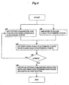
- Fig. 4 is a flow chart for explaining the non-uniform density sample analyzing method of the present invention using the in-plane diffraction measurement.
- the measurement of the X-ray scattering curve in Step s2 of the non-uniform density analyzing method described in the Japanese Patent Application No. 2001-088652 shown in Fig. 11 is made by the in-plane diffraction measurement (Step s20).
- Step s10 the fitting between the measured in-plane X-ray scattering curve and a simulated X-ray scattering curve calculated separately (Step s10) is performed (Step s30), and the value of the fitting parameter obtained when the simulated x-ray scattering curve and the in-plane X-ray scattering curve agree with each other serves to indicate the distribution state of the particle-like matter in the non-uniform density sample in the in-plane direction (Steps s40 and s50).
- the simulated X-ray scattering curve is calculated (Step s10) by using a scattering function that represents an X-ray scattering curve according to the fitting parameter that indicates the distribution state of the particle-like matter and by arbitrarily selecting the value of the fitting parameter.
- the fitting parameter that represents the distribution state of the particle-like matter in the in-plane direction is used.
- the following Eq. 1 illustrates one example of the scattering function to which the fitting parameters that represent the distribution state of the particle-like matter in the in-plane direction are introduced.
- the fitting parameters of the scattering function given in this Eq. 1 are the mean diameter parameter R o of the particle-like matter, the distribution shape parameter M, the shortest distance parameter D between the particle-like matters, and the correlation order parameter ⁇ of the particle-like matter.
- the conditions are set equal to in-plane diffraction measurement conditions.
- Steps s1 and s3 shown in Fig. 11 are removed from the flow chart of Fig. 4.
- Steps s30 and s40 it is determined whether the simulated X-ray scattering curve agrees with the in-plane X-ray scattering curve. If they do not agree, then the values of the fitting parameters are changed, the simulated X-ray scattering curve is recalculated, and it is determined whether the recalculated simulated X-ray scattering curve agrees with the in-plane scattering curve.
- the values of the fitting parameters obtained when they agree are values that represent the in-plane direction distribution state of the particle-like matter in the non-uniform density sample of the analysis target (Step s50).
- the mean diameter R o , the distribution shape M, the shortest distance D, and the correlation order ⁇ of the particle-like matter are analyzed in the in-plane direction.
- the X-ray incident angle ⁇ in is variously changed during the in-plane diffraction measurement and the penetrating depth of the X-ray in the sample is changed, whereby the in-plane direction distribution of the particle-like matter at any depth position in the sample can be analyzed.
- Fig. 7 illustrates one example of a change in the penetrating depth [nm] relative to the X-ray incident angle ⁇ in .
- the penetrating depth of the X-ray is only 3 nanometers. If the in-plane diffraction measurement is made in this state, the in-plane direction distribution on a very surface of the penetrating depth of 3 nanometers can be analyzed. If the incident angle is set at about 0.3°, then the penetrating depth exceeds 200 nanometers and a structural analysis within the range of this depth can be performed.
- the structure of the thin film often changes on a surface and an inside thereof. Therefore, the analysis of the sample in the depth direction by variously changing the X-ray incident angle is quite effective. For example, it is possible to simply and accurately determine whether the film is formed uniformly in the depth direction.
- Fig. 5 is a block diagram for explaining a non-uniform density sample analyzing device for executing the non-uniform density sample analyzing method described above and a non-uniform density analyzing system that includes the non-uniform density analyzing device.
- the analyzing system according to the present invention includes an in-plane diffraction measurement device (4) that measures in-plane diffraction in place of an X-ray measurement device (2) in the non-uniform density analyzing system described in the Japanese Patent Application No. 2001-088656 shown in Fig. 12.
- the in-plane diffraction measurement device (4) a conventional, well-known device can be employed.
- a device proposed by the present inventor see Japanese Patent Application Laid-Open No. 11-287773.
- 11-287773 is constituted so that a parabolic multilayer monochromator formed by alternately providing heavy element layers and light element layers a plurality of times and having a surface, on which an X-ray is incident, formed as a paraboloid so as to facilitate creating a parallel X-ray beam having a large intensity and to realize highly reliable in-plane diffraction measurement even at experimental level and so that a goniometer capable of scanning the X-ray not only in a direction orthogonal to the surface but also a direction parallel to the surface is combined with the parabolic multilayer film monochromator.
- the analyzing system of the present invention can realize the analysis of the particle-like matter in the in-plane direction using the in-plane X-ray scattering curve by the highly reliable in-plane diffraction measurement without the need of large-scale equipment. If the device disclosed in the Japanese Patent Application Laid-Open No. 11-287773 is applied to the present invention, the device is not specially adjusted or changed either structurally or operationally. Therefore, reference is made to the Japanese Patent Application Laid-Open No. 11-287773 for the detailed description of the structure and operation of the device.
- the non-uniform density sample analyzing device (3) includes a function storage means (301) which stores a scattering function (e.g., Equation 1) having fitting parameters that represent the distribution of the particles in the in-plane direction, a simulation means (302) which calculates a simulated X-ray scattering curve using the scattering function from the function storage means (301), and a fitting means (303) which performs fitting between the simulated X-ray scattering curve from the simulation means (302) and the in-plane X-ray scattering curve from the in-plane diffraction measuring device (4).
- a scattering function e.g., Equation 1
- a simulation means which calculates a simulated X-ray scattering curve using the scattering function from the function storage means (301)
- a fitting means (303) which performs fitting between the simulated X-ray scattering curve from the simulation means (302) and the in-plane X-ray scattering curve from the in-plane diffraction measuring device (4).
- the simulation means (302) repeatedly calculates the simulated X-ray scattering curve while selecting and changing the fitting parameter using the least square method or the like. Then, the value of the fitting parameter obtained when the both curves agree is output, as an analysis result that represents a distribution state of the particle-like matter in the non-uniform density sample in the in-plane direction, to output means (304) and (305) such as a display, a printer, and a storage means.
- non-uniform density sample analyzing method of the present invention calculation steps such as simulation and fitting steps are executed using a computer (a calculator such as a general-purpose computer or an analysis-dedicated computer).
- the non-uniform density sample analyzing device that the present invention also provides can be realized as, for example, software for executing functions of the above-stated means.
- the non-uniform density sample analyzing system that the present invention further provides is preferably constituted so that data and signals can be transmitted and received between the in-plane diffraction measurement device and the non-uniform density sample analyzing device in either both or one direction.
- Fig. 8 illustrates the simulated X-ray scattering curve obtained by the scattering function of Equation 1 and the in-plane X-ray scattering curve obtained by the in-plane diffraction measurement. As is obvious from Fig. 8, the excellent fitting of the both curves is realized. The fitting parameters when the both curves agree are as follows:
- Fig. 9 illustrates the relationship between the particle diameter and the structural factor S(Q).
- the distribution state such as the particle diameter distribution of the particle-like matter even in the anisotropic non-uniform density sample in the in-plane direction can be simply, highly accurately analyzed.
Landscapes
- Chemical & Material Sciences (AREA)
- Crystallography & Structural Chemistry (AREA)
- Physics & Mathematics (AREA)
- Health & Medical Sciences (AREA)
- Life Sciences & Earth Sciences (AREA)
- Analytical Chemistry (AREA)
- Biochemistry (AREA)
- General Health & Medical Sciences (AREA)
- General Physics & Mathematics (AREA)
- Immunology (AREA)
- Pathology (AREA)
- Analysing Materials By The Use Of Radiation (AREA)
- Extrusion Moulding Of Plastics Or The Like (AREA)
- Transition And Organic Metals Composition Catalysts For Addition Polymerization (AREA)
- Cosmetics (AREA)
Abstract
Description
- The present invention relates to a method, device and system for analyzing a non-uniform density sample, and more particularly to a novel non-uniform density sample analyzing method, non-uniform density sample analyzing device and non-uniform density sample analyzing system capable of simply, accurately analyzing an in-plane direction distribution state of particle-like matter in the non-uniform density sample.
- A method for analyzing a particle diameter distribution in a non-uniform density sample such as a porous film by using an X-ray has been newly proposed by the inventors of the present invention (see Japanese Patent Application No. 2001-088656). In this method, a diffuse scattering intensity of the X-ray is measured and the particle diameter distribution is analyzed based on the measured intensity, thereby realizing an excellent analyzing ability.
- However, there is yet room for improvement in such an excellent analyzing method so as to achieve another new advantage.
- That is, with the non-uniform density sample analyzing method disclosed in the Japanese Patent Application No. 2001-088656, it is difficult to completely analyze the density non-uniformity of an anisotropic non-uniform density sample.
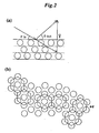
- To be specific, a non-anisotropic non-uniform density sample is a sample in which particle-like matter such as fine particle and pore has a random distribution as shown in, for example, Fig. 1(a). Conversely, as shown in, for example, Figs. 2(a) and 2(b), the anisotropic non-uniform density sample is a sample in which the distribution of particle-like matter has some regularity or directivity in an in-plane direction. In the example of Fig. 2(b), the particle-like matter is distributed in the in-plane direction with the regularity in which clusters each having two pentagons connected to each other are formed.
- As for the non-anisotropic non-uniform density sample, if an X-ray scattering curve is measured by scanning an X-ray outgoing angle θout with an X-ray incident angle θin being constant in a condition of, for example, θin = θout + offset Δω, the density non-uniformity of the sample in a direction corresponding to a direction of a scattering vector q shown in Figs. 1(a) and 1(b), i.e., a direction near a plane normal is measured as described in the Japanese Patent Application No. 2001-088656. This is so-called out-of-plane diffraction measurement.
- If this out-of-plane diffraction measurement is directly applied to the anisotropic non-uniform density sample, the non-uniformity of the sample is measured along the scattering vector q in the direction near the plane normal shown in Figs. 2(a) and 2(b) similarly to Fig. 1. This means that the anisotropic non-uniform density sample cannot be analyzed in an in-plane direction of the sample. With the non-anisotropic non-uniform density sample, by contrast, the in-plane direction of the sample is random. Therefore, even if a scan direction is changed, the particle-like matter can be observed without any changes and thus no disadvantage occurs. With the anisotropic non-uniform density sample, however, because of the regularity of the particles in the in-plane direction as described above, the particle-like matter is observed differently according to the scan direction. As a result, the particle diameter distribution in the in-plane direction cannot be analyzed with the out-of-plane diffraction measurement.
- The present invention has been achieved in light of these situations and it is an object of the present invention to provide a novel non-uniform density sample analyzing method as well as a non-uniform density sample analyzing device and a non-uniform density sample analyzing system capable of simply and highly accurately analyzing the distribution state of the particle-like matter in the anisotropic non-uniform density sample in the in-plane direction.
- In order to achieve the foregoing, the present invention, provides a non-uniform density sample analyzing method comprising the steps of: calculating a simulated X-ray scattering curve under the same condition as a measurement condition of an actually measured X-ray scattering curve by using a scattering function which represents an X-ray scattering curve according to a fitting parameter which indicates distribution sate of particle-like matter; and carrying out fitting between the simulated X-ray scattering curve and the actually measured X-ray scattering curve while changing the fitting parameter, wherein the value of the fitting parameter when the simulated X-ray scattering curve agrees with the actually measured X-ray scattering curve serves to indicate the distribution state of the particle-like matter in a non-uniform density sample, thereby analyzing the distribution state of the particle-like matter in the non-uniform density sample, wherein the actually measured X-ray scattering curve is an in-plane X-ray scattering curve obtained by in-plane diffraction measurement, wherein the fitting is carried out between the in-plane X-ray scattering curve and the simulated X-ray scattering curve, and wherein the value of the fitting parameter when the simulated X-ray scattering curve agrees with the in-plane X-ray scattering curve serves to indicate the in-plane direction distribution state of the particle-like matter in the non-uniform density sample (Claim 1). The present invention also provides the analyzing method, wherein the fitting parameter of the scattering function indicates the in-plane direction distribution state of the particle-like matter (Claim 2).
- Further, the present invention provides a non-uniform density sample analyzing device, comprising: function storage means for storing a scatting function which represents an X-ray scattering curve according to a fitting parameter which indicates distribution state of particle-like matter; simulation means for calculating a simulated X-ray scattering curve in the same condition as a measurement condition of an actually measured X-ray scattering curve by using the scattering function stored in the function storage means; and fitting means for carrying out fitting between the simulated X-ray scattering curve and the actually measured X-ray scattering curve while changing the fitting parameter, and wherein the value of the fitting parameter when the simulated X-ray scattering curve agrees with the actually measured X-ray scattering curve serves to indicate the distribution state of the particle-like matter in a non-uniform density sample, wherein the actually measured X-ray scattering curve is an in-plane X-ray scattering curve obtained by in-plane diffraction measurement, wherein the fitting is carried out between the in-plane X-ray scattering curve and the simulated X-ray scattering curve, and wherein the value of the fitting parameter when the simulated X-ray scattering curve agrees with the in-plane X-ray scattering curve serves to indicate the in-plane direction distribution state of the particle-like matter in the non-uniform density sample (Claim 3). The present invention also provides the analyzing device, wherein the fitting parameter of the scattering function indicates the in-plane direction distribution state of the particle-like matter (Claim 4).
- Moreover, the present invention provides a non-uniform density sample analyzing system for analyzing distribution state of particle-like matter in a non-uniform density sample, comprising: an in-plane diffraction measuring device which performs in-plane diffraction measurement of an actually measured X-ray scattering curve for the non-uniform density sample; and the non-uniform density sample analyzing device according to
claim -
- Figs. 1(a) and 1(b) are illustrations each for explaining out-of-plane diffraction measurement conducted to a non-anisotropic non-uniform density sample.
- Figs. 2(a) and 2(b) are illustrations each for explaining out-of-plane diffraction measurement conducted to an anisotropic non-uniform density sample.
- Figs. 3(a), 3(b), and 3(c) are illustrations each for explaining in-plane diffraction measurement conducted to the anisotropic non-uniform density sample.
- Fig. 4 is a flow chart for explaining a non-uniform density sample analyzing method according to the present invention.
- Fig. 5 is a block diagram for explaining a non-uniform density sample analyzing device and a non-uniform density sample analyzing system according to the present invention.
- Fig. 6 illustrates a particle diameter model as a shape model of particle-like matter.
- Fig. 7 illustrates the relationship among an X-ray incident angle, a penetrating depth, and a reflectivity.
- Fig. 8 illustrates a simulated X-ray scattering curve and an in-plane X-ray scattering curve as one example of the present invention.
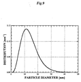
- Fig. 9 illustrates a particle distribution of particles in an in-plane direction as one example.
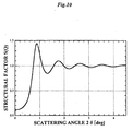
- Fig. 10 illustrates a structural factor of the particle-particle correlation as one example.
- Fig. 11 is a flow chart for explaining a non-uniform density sample analyzing method described in Japanese Patent Application No. 2001-088656.
- Fig. 12 is a block diagram for explaining a non-uniform density sample analyzing device and a non-uniform density sample analyzing system described in the Japanese Patent Application No. 2001-088656.
- Reference symbols in the drawings denote the following system, device, or elements:
- 1 Non-uniform density sample analyzing system
- 2 X-ray measuring device
- 3 Non-uniform density sample analyzing device
- 31 Critical angle storage means
- 32 Function storage means
- 34 Fitting means
- 35,36 Output means
- 301 Function storage means
- 302 Simulation means
- 303 Fitting means
- 304, 305 Output means
- 4 In-plane diffraction measuring device
- The present invention applies in-plane diffraction measurement to the non-uniform density sample analyzing method described in the Japanese Patent Application No. 2001-088656 so as to realize analysis of an anisotropic non-uniform density sample in an in-plane direction.
- As shown in Fig. 3(c), the in-plane diffraction measurement utilizes in-plane diffraction wherein if an X-ray is incident on a surface of a sample at a very small incident angle θin, then an X-ray component in parallel to the sample surface appears in the sample, the X-ray component is diffracted by a crystal surface perpendicular to the sample surface and diffracted in plane at a diffraction angle 2θθ, and a diffraction line of the diffracted X-ray component is emitted at a very small angle θout relative to the sample surface.
- According to this in-plane diffraction measurement, as shown in Figs. 3(a) and 3(b), a scattering vector q' in the in-plane direction of the non-uniform density sample can be measured. Therefore, by employing the scattering vector q' (hereinafter, "in-plane X-ray scattering curve") as an actually measured X-ray scattering curve in the non-uniform density analyzing method described in the Japanese Patent Application No. 2001-088656, the distribution state of the particle-like matter in the in-plane direction can be accurately analyzed.
- Fig. 4 is a flow chart for explaining the non-uniform density sample analyzing method of the present invention using the in-plane diffraction measurement. As shown in Fig. 4, with the analyzing method of the present invention, the measurement of the X-ray scattering curve in Step s2 of the non-uniform density analyzing method described in the Japanese Patent Application No. 2001-088652 shown in Fig. 11 is made by the in-plane diffraction measurement (Step s20). Then, the fitting between the measured in-plane X-ray scattering curve and a simulated X-ray scattering curve calculated separately (Step s10) is performed (Step s30), and the value of the fitting parameter obtained when the simulated x-ray scattering curve and the in-plane X-ray scattering curve agree with each other serves to indicate the distribution state of the particle-like matter in the non-uniform density sample in the in-plane direction (Steps s40 and s50).
- The simulated X-ray scattering curve is calculated (Step s10) by using a scattering function that represents an X-ray scattering curve according to the fitting parameter that indicates the distribution state of the particle-like matter and by arbitrarily selecting the value of the fitting parameter. In this case, according to the present invention, since the distribution state of the particle-like matter in the in-plane direction is to be analyzed, the fitting parameter that represents the distribution state of the particle-like matter in the in-plane direction is used. The following Eq. 1 illustrates one example of the scattering function to which the fitting parameters that represent the distribution state of the particle-like matter in the in-plane direction are introduced.

- q=¦q¦: Magnitude of scattering vector
- q: Scattering vector
- λ: X-ray wavelength
- Ro: Mean diameter parameter of particle-like matter
- M: Distribution shape parameter
- D: Shortest distance parameter between particle-like matters
- η: Correlation order parameter of particle-like matter
- The fitting parameters of the scattering function given in this Eq. 1 are the mean diameter parameter Ro of the particle-like matter, the distribution shape parameter M, the shortest distance parameter D between the particle-like matters, and the correlation order parameter η of the particle-like matter.
- Naturally, it is necessary to calculate the simulated X-ray scattering curve in the same conditions as those for the scattering curve. Therefore, the conditions are set equal to in-plane diffraction measurement conditions.
- In the in-plane diffraction, there is no need to measure a reflectivity curve. Due to this, Steps s1 and s3 shown in Fig. 11 are removed from the flow chart of Fig. 4.
- In Steps s30 and s40, it is determined whether the simulated X-ray scattering curve agrees with the in-plane X-ray scattering curve. If they do not agree, then the values of the fitting parameters are changed, the simulated X-ray scattering curve is recalculated, and it is determined whether the recalculated simulated X-ray scattering curve agrees with the in-plane scattering curve.
- These steps are repeated while adjusting and changing the values of the fitting parameters until the both curves agree with each other. The values of the fitting parameters obtained when they agree are values that represent the in-plane direction distribution state of the particle-like matter in the non-uniform density sample of the analysis target (Step s50). In case of the Eq. 1, the mean diameter Ro, the distribution shape M, the shortest distance D, and the correlation order η of the particle-like matter are analyzed in the in-plane direction.
- With this non-uniform density sample analyzing method, the X-ray incident angle θin is variously changed during the in-plane diffraction measurement and the penetrating depth of the X-ray in the sample is changed, whereby the in-plane direction distribution of the particle-like matter at any depth position in the sample can be analyzed.
- Fig. 7 illustrates one example of a change in the penetrating depth [nm] relative to the X-ray incident angle θin. As can be seen from Fig. 7, if the X-ray is incident on an Si surface at, for example, 0.1°, the penetrating depth of the X-ray is only 3 nanometers. If the in-plane diffraction measurement is made in this state, the in-plane direction distribution on a very surface of the penetrating depth of 3 nanometers can be analyzed. If the incident angle is set at about 0.3°, then the penetrating depth exceeds 200 nanometers and a structural analysis within the range of this depth can be performed. If the sample is a thin film, the structure of the thin film often changes on a surface and an inside thereof. Therefore, the analysis of the sample in the depth direction by variously changing the X-ray incident angle is quite effective. For example, it is possible to simply and accurately determine whether the film is formed uniformly in the depth direction.
- Fig. 5 is a block diagram for explaining a non-uniform density sample analyzing device for executing the non-uniform density sample analyzing method described above and a non-uniform density analyzing system that includes the non-uniform density analyzing device. As illustrated by Fig. 5, the analyzing system according to the present invention includes an in-plane diffraction measurement device (4) that measures in-plane diffraction in place of an X-ray measurement device (2) in the non-uniform density analyzing system described in the Japanese Patent Application No. 2001-088656 shown in Fig. 12.
- As the in-plane diffraction measurement device (4), a conventional, well-known device can be employed. For example, there is known a device proposed by the present inventor (see Japanese Patent Application Laid-Open No. 11-287773). The device disclosed in the Japanese Patent Application Laid-Open No. 11-287773 is constituted so that a parabolic multilayer monochromator formed by alternately providing heavy element layers and light element layers a plurality of times and having a surface, on which an X-ray is incident, formed as a paraboloid so as to facilitate creating a parallel X-ray beam having a large intensity and to realize highly reliable in-plane diffraction measurement even at experimental level and so that a goniometer capable of scanning the X-ray not only in a direction orthogonal to the surface but also a direction parallel to the surface is combined with the parabolic multilayer film monochromator. By employing this device as the in-plane diffraction measuring device (4), the analyzing system of the present invention can realize the analysis of the particle-like matter in the in-plane direction using the in-plane X-ray scattering curve by the highly reliable in-plane diffraction measurement without the need of large-scale equipment. If the device disclosed in the Japanese Patent Application Laid-Open No. 11-287773 is applied to the present invention, the device is not specially adjusted or changed either structurally or operationally. Therefore, reference is made to the Japanese Patent Application Laid-Open No. 11-287773 for the detailed description of the structure and operation of the device.
- Meanwhile, the non-uniform density sample analyzing device (3) includes a function storage means (301) which stores a scattering function (e.g., Equation 1) having fitting parameters that represent the distribution of the particles in the in-plane direction, a simulation means (302) which calculates a simulated X-ray scattering curve using the scattering function from the function storage means (301), and a fitting means (303) which performs fitting between the simulated X-ray scattering curve from the simulation means (302) and the in-plane X-ray scattering curve from the in-plane diffraction measuring device (4). Until the fitting means (303) determines that the simulated X-ray scattering curve agrees with the in-plane X-ray scattering curve, the simulation means (302) repeatedly calculates the simulated X-ray scattering curve while selecting and changing the fitting parameter using the least square method or the like. Then, the value of the fitting parameter obtained when the both curves agree is output, as an analysis result that represents a distribution state of the particle-like matter in the non-uniform density sample in the in-plane direction, to output means (304) and (305) such as a display, a printer, and a storage means.
- In the non-uniform density sample analyzing method of the present invention, calculation steps such as simulation and fitting steps are executed using a computer (a calculator such as a general-purpose computer or an analysis-dedicated computer). In addition, the non-uniform density sample analyzing device that the present invention also provides can be realized as, for example, software for executing functions of the above-stated means. Further, the non-uniform density sample analyzing system that the present invention further provides is preferably constituted so that data and signals can be transmitted and received between the in-plane diffraction measurement device and the non-uniform density sample analyzing device in either both or one direction.
- An actual analysis result for the anisotropic non-uniform density sample will now be explained.
- Fig. 8 illustrates the simulated X-ray scattering curve obtained by the scattering function of
Equation 1 and the in-plane X-ray scattering curve obtained by the in-plane diffraction measurement. As is obvious from Fig. 8, the excellent fitting of the both curves is realized. The fitting parameters when the both curves agree are as follows: - Mean diameter parameter Ro = 7.0 nm,
- Distribution shape parameter M = 5.0,
- Shortest distance parameter D = 10 nm, and
- Correlation order parameter η = 0.28.
- These values are the mean diameter, the distribution shape, the shortest distance, and the correlation order of the particle-like matter in the anisotropic non-uniform density sample in this example. The diameter distribution of the particle-like matter in the in-plane direction is shown in Fig. 9. And, Fig. 10 illustrates the relationship between the particle diameter and the structural factor S(Q).
- Needless to say, this invention is not limited to the embodiment and various modifications can be made to details of the invention.
- As described above in detail, according to the non-uniform density sample analyzing method, the non-uniform density sample analyzing device, and the non-uniform density sample analyzing system of the present invention, the distribution state such as the particle diameter distribution of the particle-like matter even in the anisotropic non-uniform density sample in the in-plane direction can be simply, highly accurately analyzed.
Claims (5)
- A non-uniform density sample analyzing method comprising the steps of:calculating a simulated X-ray scattering curve under the same condition as a measurement condition of an actually measured X-ray scattering curve by using a scattering function which represents an X-ray scattering curve according to a fitting parameter which indicates distribution sate of particle-like matter; andcarrying out fitting between the simulated X-ray scattering curve and the actually measured X-ray scattering curve while changing the fitting parameter,wherein the value of the fitting parameter when the simulated X-ray scattering curve agrees with the actually measured X-ray scattering curve serves to indicate the distribution state of the particle-like matter in a non-uniform density sample, thereby analyzing the distribution state of the particle-like matter in the non-uniform density sample,
wherein the actually measured X-ray scattering curve is an in-plane X-ray scattering curve obtained by in-plane diffraction measurement,
wherein the fitting is carried out between the in-plane X-ray scattering curve and the simulated X-ray scattering curve, and
wherein the value of the fitting parameter when the simulated X-ray scattering curve agrees with the in-plane X-ray scattering curve serves to indicate the in-plane direction distribution state of the particle-like matter in the non-uniform density sample. - The non-uniform density sample analyzing method according to claim 1, wherein the fitting parameter of the scattering function indicates the in-plane direction distribution state of the particle-like matter.
- A non-uniform density sample analyzing device, comprising:function storage means for storing a scatting function which represents an X-ray scattering curve according to a fitting parameter which indicates distribution state of particle-like matter;simulation means for calculating a simulated X-ray scattering curve in the same condition as a measurement condition of an actually measured X-ray scattering curve by using the scattering function stored in the function storage means; andfitting means for carrying out fitting between the simulated X-ray scattering curve and the actually measured X-ray scattering curve while changing the fitting parameter, andwherein the value of the fitting parameter when the simulated X-ray scattering curve agrees with the actually measured X-ray scattering curve serves to indicate the distribution state of the particle-like matter in a non-uniform density sample,
wherein the actually measured X-ray scattering curve is an in-plane X-ray scattering curve obtained by in-plane diffraction measurement,
wherein the fitting is carried out between the in-plane X-ray scattering curve and the simulated X-ray scattering curve, and
wherein the value of the fitting parameter when the simulated X-ray scattering curve agrees with the in-plane X-ray scattering curve serves to indicate the in-plane direction distribution state of the particle-like matter in the non-uniform density sample. - The non-uniform density sample analyzing device according to claim 3, wherein the fitting parameter of the scattering function indicates the in-plane direction distribution state of the particle-like matter.
- A non-uniform density sample analyzing system for analyzing distribution state of particle-like matter in a non-uniform density sample, comprising:an in-plane diffraction measuring device which performs in-plane diffraction measurement of an actually measured X-ray scattering curve for the non-uniform density sample; andthe non-uniform density sample analyzing device according to claim 3 or 4.
Applications Claiming Priority (3)
| Application Number | Priority Date | Filing Date | Title |
|---|---|---|---|
| JP2001195112A JP3953754B2 (en) | 2001-06-27 | 2001-06-27 | Non-uniform density sample analysis method and apparatus and system thereof |
| JP2001195112 | 2001-06-27 | ||
| PCT/JP2002/006013 WO2003002997A1 (en) | 2001-06-27 | 2002-06-17 | Nonuniform-density sample analyzing method, device, and system |
Publications (3)
| Publication Number | Publication Date |
|---|---|
| EP1413878A1 true EP1413878A1 (en) | 2004-04-28 |
| EP1413878A4 EP1413878A4 (en) | 2007-12-05 |
| EP1413878B1 EP1413878B1 (en) | 2008-12-31 |
Family
ID=19033145
Family Applications (1)
| Application Number | Title | Priority Date | Filing Date |
|---|---|---|---|
| EP02738736A Expired - Lifetime EP1413878B1 (en) | 2001-06-27 | 2002-06-17 | Nonuniform-density sample analyzing method, device,and system |
Country Status (8)
| Country | Link |
|---|---|
| US (1) | US7116755B2 (en) |
| EP (1) | EP1413878B1 (en) |
| JP (1) | JP3953754B2 (en) |
| KR (1) | KR20040020915A (en) |
| CN (1) | CN1293382C (en) |
| DE (1) | DE60230631D1 (en) |
| TW (1) | TW562922B (en) |
| WO (1) | WO2003002997A1 (en) |
Families Citing this family (8)
| Publication number | Priority date | Publication date | Assignee | Title |
|---|---|---|---|---|
| JP4224376B2 (en) | 2003-10-20 | 2009-02-12 | 株式会社リガク | Membrane structure analysis method and apparatus |
| JP3927960B2 (en) * | 2004-03-04 | 2007-06-13 | 株式会社リガク | Method and apparatus for measuring porosity and method and apparatus for measuring particle ratio |
| FR2904421B1 (en) * | 2006-07-28 | 2008-10-31 | Areva Np Sas | NON-DESTRUCTIVE CHARACTERIZATION METHOD, NOTAMMENTLY FOR NUCLEAR FUEL PARTICLES FOR HIGH TEMPERATURE REACTOR |
| US7848483B2 (en) * | 2008-03-07 | 2010-12-07 | Rigaku Innovative Technologies | Magnesium silicide-based multilayer x-ray fluorescence analyzers |
| FI20095843A7 (en) * | 2009-08-14 | 2011-02-15 | Con Boys Oy | Method and system for analyzing data measured by scattering measurements from disordered material |
| JP5658219B2 (en) * | 2012-11-21 | 2015-01-21 | 住友ゴム工業株式会社 | Method for evaluating energy loss, chipping resistance and wear resistance of polymer materials |
| JP7221536B2 (en) * | 2019-12-27 | 2023-02-14 | 株式会社リガク | Scattering measurement analysis method, scattering measurement analysis apparatus, and scattering measurement analysis program |
| CN112630611B (en) * | 2020-12-14 | 2022-04-22 | 华南理工大学 | Test method for detecting uniformity of basin-type insulator by ultrasonic longitudinal wave reflection method |
Family Cites Families (13)
| Publication number | Priority date | Publication date | Assignee | Title |
|---|---|---|---|---|
| US5200910A (en) * | 1991-01-30 | 1993-04-06 | The Board Of Trustees Of The Leland Stanford University | Method for modelling the electron density of a crystal |
| GB9226552D0 (en) * | 1992-12-21 | 1993-02-17 | Philips Electronics Uk Ltd | A method of determining a given characteristic of a material sample |
| GB2289833B (en) * | 1994-05-24 | 1998-04-22 | Mitsubishi Electric Corp | Method and apparatus for evaluating thin-film multilayer structure |
| JPH08145916A (en) * | 1994-11-18 | 1996-06-07 | Hitachi Ltd | Small angle X-ray equipment |
| US6192103B1 (en) * | 1999-06-03 | 2001-02-20 | Bede Scientific, Inc. | Fitting of X-ray scattering data using evolutionary algorithms |
| JP2001056304A (en) * | 1999-06-10 | 2001-02-27 | Rigaku Corp | Pole measuring method |
| US6937694B2 (en) | 1999-06-10 | 2005-08-30 | Rigaku Corporation | Pole measuring method |
| JP2001349849A (en) | 2000-04-04 | 2001-12-21 | Rigaku Corp | Non-uniform density sample analysis method and its apparatus and system |
| US6895075B2 (en) * | 2003-02-12 | 2005-05-17 | Jordan Valley Applied Radiation Ltd. | X-ray reflectometry with small-angle scattering measurement |
| GB0116825D0 (en) * | 2001-07-10 | 2001-08-29 | Koninl Philips Electronics Nv | Determination of material parameters |
| KR100879729B1 (en) * | 2002-06-06 | 2009-01-22 | 가부시끼가이샤 리가쿠 | Density nonuniform multilayer film analysis method, apparatus and system |
| JP3697246B2 (en) * | 2003-03-26 | 2005-09-21 | 株式会社リガク | X-ray diffractometer |
| JP4224376B2 (en) * | 2003-10-20 | 2009-02-12 | 株式会社リガク | Membrane structure analysis method and apparatus |
-
2001
- 2001-06-27 JP JP2001195112A patent/JP3953754B2/en not_active Expired - Fee Related
-
2002
- 2002-06-17 CN CNB028129989A patent/CN1293382C/en not_active Expired - Fee Related
- 2002-06-17 KR KR10-2003-7015865A patent/KR20040020915A/en not_active Withdrawn
- 2002-06-17 US US10/482,022 patent/US7116755B2/en not_active Expired - Lifetime
- 2002-06-17 WO PCT/JP2002/006013 patent/WO2003002997A1/en not_active Ceased
- 2002-06-17 EP EP02738736A patent/EP1413878B1/en not_active Expired - Lifetime
- 2002-06-17 DE DE60230631T patent/DE60230631D1/en not_active Expired - Lifetime
- 2002-06-20 TW TW091113458A patent/TW562922B/en active
Non-Patent Citations (7)
| Title |
|---|
| CICCARIELLO S ET AL: "POLYDISPERSE DISTRIBUTIONS OF COMPOSITE PARTICLES AND THE SAXS BEHAVIOUR OF LOW-RANK COALS" EUROPHYS LETT DEC 1 1987, vol. 4, no. 11, 1 December 1987 (1987-12-01), pages 1279-1284, XP002456223 * |
| JOURNAL ARTICLE: 'Advanced Thin Film X-ray system-Grazing incidence in-plane diffractometer' RIGAKU JOURNAL vol. 16, no. 1, 1999, RIGAKU DENKI K.K., JP, pages 53 - 58, XP008085203 * |
| MATSUNO S Y ET AL: "Kokyodo X-sen to Tajiku Gonio o Yusuru Usumaku Kaiseki Sochi ni yoru X-sen hansharitsu Sokutei to Fukasa Seigyo In-Plane X-sen Kaisetsu (X-Ray Reflectivity and Depth-Resolved In-Plane X-Ray Diffraction Studies of Thin Films Using a High Performance Grazing incidence X-Ray Scattering Apparatus" X-SEN BUNSEKI NO SHINPO - ADVANCES IN X-RAY CHEMICAL ANALYSIS, JAPAN, AGUNE GIJUTSU SENTA, TOKYO,, JP, vol. 30, no. 34TH SERIES, 1999, pages 189-203, XP003011515 ISSN: 0911-7806 * |
| MITTELBACH R ET AL: "Direct structure analysis of small-angle scattering data from polydisperse colloidal particles" JOURNAL OF APPLIED CRYSTALLOGRAPHY MUNKSGAARD INTERNATIONAL BOOKSELLERS & PUBLISHERS DENMARK, vol. 31, 1 August 1998 (1998-08-01), pages 600-608, XP002456225 ISSN: 0021-8898 * |
| OMOTE K: "DIRECT OBSERVATION OF IN-PLANE TEXTURE IN COBALT RECORDING MEDIA BY MEANS OF A LABORATORY-SCALE X-RAY DIFFRACTOMETER" X-RAY SPECTROMETRY, WILEY-HEYDEN, US, vol. 28, no. 6, November 1999 (1999-11), pages 440-445, XP009034007 ISSN: 0049-8246 * |
| RE FIORENTIN S: "A new method for determination of particle-size distribution function from small angle scattering data" JOURNAL OF APPLIED PHYSICS USA, vol. 53, no. 1, January 1982 (1982-01), pages 245-249, XP002456224 ISSN: 0021-8979 * |
| See also references of WO03002997A1 * |
Also Published As
| Publication number | Publication date |
|---|---|
| EP1413878A4 (en) | 2007-12-05 |
| DE60230631D1 (en) | 2009-02-12 |
| JP2003014663A (en) | 2003-01-15 |
| CN1520513A (en) | 2004-08-11 |
| KR20040020915A (en) | 2004-03-09 |
| CN1293382C (en) | 2007-01-03 |
| US7116755B2 (en) | 2006-10-03 |
| JP3953754B2 (en) | 2007-08-08 |
| TW562922B (en) | 2003-11-21 |
| WO2003002997A1 (en) | 2003-01-09 |
| US20040195498A1 (en) | 2004-10-07 |
| EP1413878B1 (en) | 2008-12-31 |
Similar Documents
| Publication | Publication Date | Title |
|---|---|---|
| US20030157559A1 (en) | Analyzing method for non-uniform-density sample and device and system thereof | |
| TWI729049B (en) | Raman spectroscopy based measurements in patterned structures | |
| US11131637B2 (en) | Analysis method for fine structure, apparatus, and program | |
| US11408837B2 (en) | Analysis method for fine structure, and apparatus and program thereof | |
| JP3726080B2 (en) | Method for evaluating orientation of polycrystalline materials | |
| EP1413878A1 (en) | Nonuniform-density sample analyzing method, device,and system | |
| US8008621B2 (en) | Apparatus of measuring the orientation relationship between neighboring grains using a goniometer in a transmission electron microscope and method for revealing the characteristics of grain boundaries | |
| JP2005121613A (en) | Membrane structural analysis method and apparatus of the same | |
| CN114018898B (en) | A method for crystal orientation of forsterite based on polarized laser Raman spectroscopy | |
| US7272206B2 (en) | Method and apparatus for void content measurement and method and apparatus for particle content measurement | |
| Bauch et al. | Innovative Analysis of X‐ray Microdiffraction Images on Selected Applications of the Kossel Technique | |
| US7337098B2 (en) | Diffraction condition simulation device, diffraction measurement system, and crystal analysis system | |
| Alimohammadi et al. | Reliability analysis of traffic noise estimates in highways of Tehran by Monte Carlo simulation method | |
| Stoev et al. | Quick X-ray reflectivity of spherical samples | |
| KR100879729B1 (en) | Density nonuniform multilayer film analysis method, apparatus and system | |
| Pilch et al. | Comparison of pressure and intensity methods in evaluating the directional diffusion coefficient | |
| CN110333178A (en) | Shale pyrite pore characterization method and its application | |
| Cox et al. | Surface characterization for room acoustic modelling and design | |
| Meeker et al. | Improved methodology for inspection reliability assessment for detecting synthetic hard alpha inclusions in titanium | |
| JP2024136084A (en) | Analysis device, analysis method, and analysis program | |
| Briggs et al. | Materials characterization by surface acoustic waves from 200 MHz to 20 GHz | |
| Zainab | Electron Backscatter Diffraction of Gold Nanoparticles | |
| JPH0750332A (en) | Evaluation method and measurement method of simulation |
Legal Events
| Date | Code | Title | Description |
|---|---|---|---|
| PUAI | Public reference made under article 153(3) epc to a published international application that has entered the european phase |
Free format text: ORIGINAL CODE: 0009012 |
|
| 17P | Request for examination filed |
Effective date: 20040122 |
|
| AK | Designated contracting states |
Kind code of ref document: A1 Designated state(s): AT BE CH CY DE DK ES FI FR GB GR IE IT LI LU MC NL PT SE TR |
|
| A4 | Supplementary search report drawn up and despatched |
Effective date: 20071107 |
|
| GRAP | Despatch of communication of intention to grant a patent |
Free format text: ORIGINAL CODE: EPIDOSNIGR1 |
|
| RBV | Designated contracting states (corrected) |
Designated state(s): DE GB |
|
| GRAS | Grant fee paid |
Free format text: ORIGINAL CODE: EPIDOSNIGR3 |
|
| GRAA | (expected) grant |
Free format text: ORIGINAL CODE: 0009210 |
|
| AK | Designated contracting states |
Kind code of ref document: B1 Designated state(s): DE GB |
|
| REG | Reference to a national code |
Ref country code: GB Ref legal event code: FG4D |
|
| REF | Corresponds to: |
Ref document number: 60230631 Country of ref document: DE Date of ref document: 20090212 Kind code of ref document: P |
|
| PLBE | No opposition filed within time limit |
Free format text: ORIGINAL CODE: 0009261 |
|
| STAA | Information on the status of an ep patent application or granted ep patent |
Free format text: STATUS: NO OPPOSITION FILED WITHIN TIME LIMIT |
|
| 26N | No opposition filed |
Effective date: 20091001 |
|
| PGFP | Annual fee paid to national office [announced via postgrant information from national office to epo] |
Ref country code: GB Payment date: 20170620 Year of fee payment: 16 |
|
| GBPC | Gb: european patent ceased through non-payment of renewal fee |
Effective date: 20180617 |
|
| PG25 | Lapsed in a contracting state [announced via postgrant information from national office to epo] |
Ref country code: GB Free format text: LAPSE BECAUSE OF NON-PAYMENT OF DUE FEES Effective date: 20180617 |
|
| PGFP | Annual fee paid to national office [announced via postgrant information from national office to epo] |
Ref country code: DE Payment date: 20200618 Year of fee payment: 19 |
|
| REG | Reference to a national code |
Ref country code: DE Ref legal event code: R082 Ref document number: 60230631 Country of ref document: DE Representative=s name: DEHNSGERMANY PARTNERSCHAFT VON PATENTANWAELTEN, DE |
|
| REG | Reference to a national code |
Ref country code: DE Ref legal event code: R119 Ref document number: 60230631 Country of ref document: DE |
|
| PG25 | Lapsed in a contracting state [announced via postgrant information from national office to epo] |
Ref country code: DE Free format text: LAPSE BECAUSE OF NON-PAYMENT OF DUE FEES Effective date: 20220101 |