EP1413864A1 - Load sensor - Google Patents
Load sensor Download PDFInfo
- Publication number
- EP1413864A1 EP1413864A1 EP03730755A EP03730755A EP1413864A1 EP 1413864 A1 EP1413864 A1 EP 1413864A1 EP 03730755 A EP03730755 A EP 03730755A EP 03730755 A EP03730755 A EP 03730755A EP 1413864 A1 EP1413864 A1 EP 1413864A1
- Authority
- EP
- European Patent Office
- Prior art keywords
- load
- sensor according
- detector
- load sensor
- input unit
- Prior art date
- Legal status (The legal status is an assumption and is not a legal conclusion. Google has not performed a legal analysis and makes no representation as to the accuracy of the status listed.)
- Withdrawn
Links
Images


Classifications
-
- G—PHYSICS
- G01—MEASURING; TESTING
- G01L—MEASURING FORCE, STRESS, TORQUE, WORK, MECHANICAL POWER, MECHANICAL EFFICIENCY, OR FLUID PRESSURE
- G01L5/00—Apparatus for, or methods of, measuring force, work, mechanical power, or torque, specially adapted for specific purposes
- G01L5/22—Apparatus for, or methods of, measuring force, work, mechanical power, or torque, specially adapted for specific purposes for measuring the force applied to control members, e.g. control members of vehicles, triggers
- G01L5/225—Apparatus for, or methods of, measuring force, work, mechanical power, or torque, specially adapted for specific purposes for measuring the force applied to control members, e.g. control members of vehicles, triggers to foot actuated controls, e.g. brake pedals
-
- B—PERFORMING OPERATIONS; TRANSPORTING
- B60—VEHICLES IN GENERAL
- B60T—VEHICLE BRAKE CONTROL SYSTEMS OR PARTS THEREOF; BRAKE CONTROL SYSTEMS OR PARTS THEREOF, IN GENERAL; ARRANGEMENT OF BRAKING ELEMENTS ON VEHICLES IN GENERAL; PORTABLE DEVICES FOR PREVENTING UNWANTED MOVEMENT OF VEHICLES; VEHICLE MODIFICATIONS TO FACILITATE COOLING OF BRAKES
- B60T7/00—Brake-action initiating means
- B60T7/02—Brake-action initiating means for personal initiation
- B60T7/04—Brake-action initiating means for personal initiation foot actuated
- B60T7/042—Brake-action initiating means for personal initiation foot actuated by electrical means, e.g. using travel or force sensors
Definitions
- the present invention relates to a load sensor used in an electric braking device.
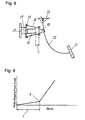
- Fig. 8 is a sectional view of the conventional load sensor.
- the conventional load sensor mounted in a car body 23 includes a first spring seat 18, a second spring seat 19, a conical spring 15, a cylindrical spring 16, a piezoelectric element 17, a pedal 21, and a brake arm 22.
- the conical spring 15 is located between the second spring seat 19 and the first spring seat 18 attached to the brake arm 22.
- a driver starts to step a pedal 21
- a load is applied to the piezoelectric element 17 via the conical spring 15, and the piezoelectric element 17 converts the load to an electric signal corresponding to the load by its piezoelectric effect and detects the load.
- Fig. 9 shows a load characteristic of the sensor. In Fig.
- the horizontal axis represents a stroke of the pedal, and the vertical axis represents the load.
- the load and a reaction by the conical spring 15 are balanced.
- the first spring seat 18 contacts the cylindrical spring 16, and then, the load and the sum of respective reactions by the conical spring 15 and the cylindrical spring 16 are balanced.
- the load characteristic of the load sensor has a fold point P, as shown in Fig. 9.
- Fig. 7 is a load characteristic diagram of a hydraulic brake.
- the horizontal axis represents a stroke of a pedal, and the vertical axis represents a load.
- the load rapidly increases when the stroke of the pedal exceeds a predetermined value.
- the fold point P is not found in the load characteristic diagram of the hydraulic brake in Fig. 7.
- a rapid change of the load at the fold point P of the conventional load sensor provides an uncomfortable pedal feeling, while the hydraulic brake does not provide an uncomfortable pedal feeling.
- a load sensor includes a load-input unit, an hourglass-shaped coil spring having an end coupled to the load-input unit, a load-applying unit provided at other end of the hourglass-shaped coil spring, and a load detector for receiving the load from the load-applying unit and detecting the load.
- the load sensor does not give a user uncomfortable pedal feeling, similarly to a hydraulic brake.
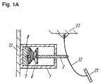
- Fig. 1A is a sectional view of a load sensor in accordance with Exemplary Embodiment 1 of the present invention.
- Fig. 1B and Fig. 1C are enlarged sectional views of a load detector of the load sensor.
- Fig. 2 is a load characteristic diagram of the load sensor in accordance with Embodiment 1.
- At least one end of a load-input unit 2 projects out of a case 1. Another end of the load-input unit 2 is connected to one end of an hourglass-shaped coil spring 6, and the other end of the hourglass-shaped coil spring 6 is provided with a load-applying unit 7.
- a load detector 8 is disposed on an inner surface of the case 1, and faces the load-applying unit 7.
- One end of the load-input unit 2 is fixed to a brake arm 22.
- the brake arm 22 has one end fixed to a car body 23 and has other end provided with a pedal 21.
- the load detector 8 includes a straining body 12 to be strained by a load applied thereto, an insulating layer 13 on the straining body 12, and a strain-resistance element 14 as a strain detector on the insulating layer 13 for detecting an amount of the strain in the straining body 12.
- the straining body 12 is made of elastic material, such as metal, that can be strained by a load applied thereto.
- the straining body 12 preferably has a shape strained easily by the applied load, and, for example, has a recess A, as shown in Fig. 1B.
- the insulating layer 13 is made of glass ceramics, such as glass enamel, ceramic, mixture of glass and ceramic, or oxide of aluminum.
- the insulating layer 13 is mounted to the strain resistance element 14 without an adhesive or the like, thus having a high reliability of a contact with the element.
- a protective layer 101 may be provided at least on the strain resistance element 14 so as to protect the strain resistance element 14.
- the strain resistance element may employ not only the strain resistance element 14 but an element for outputting a signal of another electro-physical quantity in response to an amount of a strain applied thereto.
- the load detector 8 faces the load-applying unit 7, and a surface of the load-applying unit 7 facing the load detector 8 has a projection 102.
- the projection 102 efficiently applies a load from the pedal 21 to the load detector 8.
- the projection 102 may have a semi-spherical surface to reduce variation of a point to apply the load to the load detector 8 even when the load-applying unit 7 tilts, hence increasing detection accuracy to the load of the load detector 8.
- the recess A or a through-hole formed in the load detector 8 corresponding to the projection 102 reduces a variation of the action point of the load to the load detector 8, hence increasing the detection accuracy of the load.
- the opening of the recess A or the through-hole is preferably smaller than the projection area of the projection 102.
- Fig. 2 is the load characteristic diagram according to Embodiment 1. In Fig.
- the horizontal axis represents a stroke of the pedal
- the vertical axis represents the load.
- the characteristic shown in Fig. 2 is substantially the same as the load characteristic of the hydraulic brake shown in Fig. 7, and has no fold point found therein to be smooth at a place where the load starts to increase more sharply.
- the load characteristic shown in Fig. 2 can be adjusted by appropriately designing the hourglass-shaped coil spring 6, and a variation of the size of the coil spring 6 can be easily reduced by forming it with a die or the like. This reduces the variation of the load characteristic.
- the diameter of the hourglass-shaped coil spring gradually decreases toward its center. Therefore, windings at both ends of the spring having a larger diameter is firstly displaced when the spring receives a load, and the coil spring has a smooth load curve. According to an increase of the load applied to the spring, an inner winding of the spring is then displaced, and a gradient of the load curve becomes sharp. Thus, in the hourglass-shaped coil spring, the load characteristic has no fold point found therein and has a smooth curve.
- the hourglass-shaped coil spring has a structure including two conical springs connected to each other at their ends having smaller diameters.
- This coil spring has a sharper load characteristic curve on receiving a load than a single conical spring, and hence has a load characteristic similar to that of the hydraulic brake.
- the load sensor of Embodiment 1 has a single spring, hence allowing the sensor to have a cumulative error smaller than that of a sensor including plural springs and to produce a small variation of a pedal feeling.
- Figs. 3 and 4 are sectional views of load sensors in accordance with Exemplary Embodiment 2 of the present invention.
- the load sensors of Embodiment 2 include stopper 3 and impact buffers 5, differently from a sensor of Embodiment 1.
- a load-input unit 2 having the stopper 3 is pressed into a case by a predetermined depth, namely, when a pedal 21 is stepped on by a predetermined amount, the stopper 3 contacts the impact buffers 5 provided in the case 1.
- the stopper 3 and the impact buffers 5 protects a load detector 8.
- the load sensor of Embodiment 2 being used for a brake, receives a rapid, large load, such as sudden braking.
- the stopper 3 and the impact buffers 5 prevent the load detector 8 from receiving such load exceeding the proof stress limit thereof.
- the stopper 3 disposed on the load input unit 2 may be provided in the case 1, as shown in Fig. 3, and may be outside the case 1, as shown in Fig. 4.
- the impact buffers 5 are located on the case 1 at positions corresponding to the position of the stopper 3.
- Fig. 5 is a sectional view of a load sensor in accordance with Exemplary Embodiment 3 of the present invention.
- the load sensor of Embodiment 3 includes a stopper 3 between a load-input unit 2 and a hourglass-shaped coil spring 6, differently from a sensor of Embodiment 2 shown in Fig. 3.
- Impact buffers 5 provided in the case 1 contact the stopper 3 when the load-input unit 2 is pressed into the case 1 by a predetermined depth.
- Fig. 6 is a sectional view of a load sensor in accordance with Exemplary Embodiment 4 of the present invention.
- the load sensor of Embodiment 4 includes a stroke sensor, differently from sensors of Embodiments 1 to 3.
- the stroke sensor is provided in the load sensor of Embodiment 2 shown in Fig. 3.
- a first magnet 9 is fixed to a load-input unit 2, and a first magnetic pole vector 9a of the first magnet 9 is substantially parallel with a movable direction of the load-input unit 2.
- a second magnet 10 facing the first magnet 9 is fixed in a case 1 such that the position of the magnets is fixed with respect to a load detector 8 relatively.
- a second magnetic pole vector 10a of the second magnet 10 is substantially orthogonal to the first magnetic pole vector 9a.
- a first semiconductor magnetic resistance element 11a and a second semiconductor magnetic resistance element 11b are disposed on the second magnet 10.
- the resistance elements 11a and 11b have magnetism sensing directions substantially orthogonal to both the first magnetic pole vector 9a and the second magnetic pole vector 10a.
- the semiconductor magnetic resistance element 11a faces one end of a surface of the second magnet 10 facing the first magnet 9.
- the semiconductor magnetic resistance element 11b faces other end of the surface of the magnet 10 opposite to the one end with respect to the load-input unit 2.
- the load sensor of Embodiment 4 has the load characteristic shown in Fig. 2, and a load corresponding to the stroke is determined based on the characteristic, thus allowing the stroke sensor to indirectly detect the load.
- the load sensor of Embodiment 6 detects a load directly with the load detector 8 and indirectly with the stroke sensor, hence having a fail-safe function.
- This stroke sensor can detect an amount of the stroke in a non-contact manner, hence providing the load sensor with an improved reliability.
- One of the stroke sensor and a combination of a stopper 3 and impact buffers 5 may be installed, or Both of them may be installed.
- the stroke sensor may be disposed inside the case 1, as shown in Fig. 6 or may be disposed outside the case 1.
- One end of the load-input unit 2 projecting from an opening of the case 1 may be provided with the first magnet 9, and the outer surface of the case 1 may be provided with the second magnet 10 (not shown).
- This structure allows a positional relation between a first magnetic pole vector 9a and a second magnetic pole vector 10a to be similar to that in a sensor shown in Fig. 6. If a magnetic force in the stroke sensor is diffused by its iron component, or if the stroke sensor is exposed to disturbance, such as iron powder attached to a magnetic gap, the stroke sensor may be protected by a case.
- the stroke sensor is installed in load sensors of Embodiment 2 and 4, but may be installed in load sensors of the other embodiments of the present invention.
- the load detectors 8 of Embodiments 1 to 4 have an advantage of the hourglass-shaped coil spring not only in the structure discussed above but also in another structure.
- a load sensor of the present invention has a load characteristic having no fold point and reduces an uncomfortable pedal feeling similarly to a hydraulic brake.
Landscapes
- Engineering & Computer Science (AREA)
- Physics & Mathematics (AREA)
- General Physics & Mathematics (AREA)
- Transportation (AREA)
- Mechanical Engineering (AREA)
- Braking Elements And Transmission Devices (AREA)
- Force Measurement Appropriate To Specific Purposes (AREA)
- Measurement Of Force In General (AREA)
Abstract
A load sensor includes a load-input unit, an hourglass-shaped coil spring having one end coupled to the load input unit, a load-applying unit disposed at the other end of the hourglass-shaped coil spring, and a load detector for receiving the load from the load-applying unit and detecting the load. The load sensor does not give a user an uncomfortable pedal feeling, similarly to a hydraulic brake.
Description
- The present invention relates to a load sensor used in an electric braking device.
- A conventional load sensor disclosed in Japanese Patent Laid-Open Publication No.09-254778 will be described below.
- Fig. 8 is a sectional view of the conventional load sensor. The conventional load sensor mounted in a
car body 23 includes afirst spring seat 18, asecond spring seat 19, aconical spring 15, acylindrical spring 16, apiezoelectric element 17, apedal 21, and abrake arm 22. Theconical spring 15 is located between thesecond spring seat 19 and thefirst spring seat 18 attached to thebrake arm 22. When a driver starts to step apedal 21, a load is applied to thepiezoelectric element 17 via theconical spring 15, and thepiezoelectric element 17 converts the load to an electric signal corresponding to the load by its piezoelectric effect and detects the load. Fig. 9 shows a load characteristic of the sensor. In Fig. 9, the horizontal axis represents a stroke of the pedal, and the vertical axis represents the load. When the stroke is in a range L, the load and a reaction by theconical spring 15 are balanced. When the stroke exceeds the range L, thefirst spring seat 18 contacts thecylindrical spring 16, and then, the load and the sum of respective reactions by theconical spring 15 and thecylindrical spring 16 are balanced. The load characteristic of the load sensor has a fold point P, as shown in Fig. 9. - Fig. 7 is a load characteristic diagram of a hydraulic brake. The horizontal axis represents a stroke of a pedal, and the vertical axis represents a load. In the hydraulic brake, as shown in Fig. 7, the load rapidly increases when the stroke of the pedal exceeds a predetermined value.
- The fold point P is not found in the load characteristic diagram of the hydraulic brake in Fig. 7. A rapid change of the load at the fold point P of the conventional load sensor provides an uncomfortable pedal feeling, while the hydraulic brake does not provide an uncomfortable pedal feeling.
- A load sensor includes a load-input unit, an hourglass-shaped coil spring having an end coupled to the load-input unit, a load-applying unit provided at other end of the hourglass-shaped coil spring, and a load detector for receiving the load from the load-applying unit and detecting the load.
- The load sensor does not give a user uncomfortable pedal feeling, similarly to a hydraulic brake.
-
- Fig. 1A is a sectional view of a load sensor in accordance with
Exemplary Embodiment 1 of the present invention. - Fig. 1B and Fig. 1C are enlarged sectional views of essential parts of the load sensor in accordance with
Embodiment 1. - Fig. 2 is a load characteristic diagram of the load sensor in accordance with
Embodiment 1. - Fig. 3 is a sectional view of a load sensor in accordance with
Exemplary Embodiment 2 of the invention. - Fig. 4 is a sectional view of another load sensor in accordance with
Embodiment 2. - Fig. 5 is a sectional view of a load sensor in accordance with
Exemplary Embodiment 3 of the invention. - Fig. 6 is a sectional view of a load sensor in accordance with Exemplary Embodiment 4 of the invention.
- Fig. 7 is a load characteristic diagram of a hydraulic brake.
- Fig. 8 is a sectional view of a conventional load sensor.
- Fig. 9 is a load characteristic diagram of the conventional load sensor.
- Fig. 1A is a sectional view of a load sensor in accordance with
Exemplary Embodiment 1 of the present invention. Fig. 1B and Fig. 1C are enlarged sectional views of a load detector of the load sensor. Fig. 2 is a load characteristic diagram of the load sensor in accordance withEmbodiment 1. - At least one end of a load-
input unit 2 projects out of acase 1. Another end of the load-input unit 2 is connected to one end of an hourglass-shaped coil spring 6, and the other end of the hourglass-shaped coil spring 6 is provided with a load-applyingunit 7. Aload detector 8 is disposed on an inner surface of thecase 1, and faces the load-applyingunit 7. One end of the load-input unit 2 is fixed to abrake arm 22. Thebrake arm 22 has one end fixed to acar body 23 and has other end provided with apedal 21. - The
load detector 8 will be described hereinafter. Theload detector 8 includes astraining body 12 to be strained by a load applied thereto, aninsulating layer 13 on the strainingbody 12, and a strain-resistance element 14 as a strain detector on theinsulating layer 13 for detecting an amount of the strain in thestraining body 12. The strainingbody 12 is made of elastic material, such as metal, that can be strained by a load applied thereto. Thestraining body 12 preferably has a shape strained easily by the applied load, and, for example, has a recess A, as shown in Fig. 1B. - The insulating
layer 13 is made of glass ceramics, such as glass enamel, ceramic, mixture of glass and ceramic, or oxide of aluminum. Theinsulating layer 13 is mounted to thestrain resistance element 14 without an adhesive or the like, thus having a high reliability of a contact with the element. As shown in Fig. 1C, aprotective layer 101 may be provided at least on thestrain resistance element 14 so as to protect thestrain resistance element 14. The strain resistance element may employ not only thestrain resistance element 14 but an element for outputting a signal of another electro-physical quantity in response to an amount of a strain applied thereto. - The
load detector 8 faces the load-applyingunit 7, and a surface of the load-applyingunit 7 facing theload detector 8 has a projection 102. The projection 102 efficiently applies a load from thepedal 21 to theload detector 8. The projection 102 may have a semi-spherical surface to reduce variation of a point to apply the load to theload detector 8 even when the load-applyingunit 7 tilts, hence increasing detection accuracy to the load of theload detector 8. - The recess A or a through-hole formed in the
load detector 8 corresponding to the projection 102 reduces a variation of the action point of the load to theload detector 8, hence increasing the detection accuracy of the load. The opening of the recess A or the through-hole is preferably smaller than the projection area of the projection 102. - An operation of the load sensor will be described.
- When a driver starts to step the
pedal 21, the load-input unit 2 moves together with thebrake arm 22. Then, the load-applyingunit 7 transmits the load to theload detector 8 via the hourglass-shaped coil spring 6, and the load produces a change of a strain resistance, and the change is converted to an electric signal. The load is balanced with a reaction of the hourglass-shapedcoil spring 6, and hence, the load characteristic depends on thecoil spring 6. Thecoil spring 6 has a nonlinear spring characteristic. In the nonlinear spring characteristic, the reaction of thecoil spring 6 is small when an amount of a deformation of the spring is small, and rapidly increases when the amount of the deformation exceeds a predetermined value. Fig. 2 is the load characteristic diagram according toEmbodiment 1. In Fig. 2, the horizontal axis represents a stroke of the pedal, and the vertical axis represents the load. The characteristic shown in Fig. 2 is substantially the same as the load characteristic of the hydraulic brake shown in Fig. 7, and has no fold point found therein to be smooth at a place where the load starts to increase more sharply. - The load characteristic shown in Fig. 2 can be adjusted by appropriately designing the hourglass-shaped
coil spring 6, and a variation of the size of thecoil spring 6 can be easily reduced by forming it with a die or the like. This reduces the variation of the load characteristic. - The diameter of the hourglass-shaped coil spring gradually decreases toward its center. Therefore, windings at both ends of the spring having a larger diameter is firstly displaced when the spring receives a load, and the coil spring has a smooth load curve. According to an increase of the load applied to the spring, an inner winding of the spring is then displaced, and a gradient of the load curve becomes sharp. Thus, in the hourglass-shaped coil spring, the load characteristic has no fold point found therein and has a smooth curve.
- The hourglass-shaped coil spring has a structure including two conical springs connected to each other at their ends having smaller diameters. This coil spring has a sharper load characteristic curve on receiving a load than a single conical spring, and hence has a load characteristic similar to that of the hydraulic brake.
- Additionally, the load sensor of
Embodiment 1 has a single spring, hence allowing the sensor to have a cumulative error smaller than that of a sensor including plural springs and to produce a small variation of a pedal feeling. - Figs. 3 and 4 are sectional views of load sensors in accordance with
Exemplary Embodiment 2 of the present invention. The load sensors ofEmbodiment 2 includestopper 3 andimpact buffers 5, differently from a sensor ofEmbodiment 1. When a load-input unit 2 having thestopper 3 is pressed into a case by a predetermined depth, namely, when apedal 21 is stepped on by a predetermined amount, thestopper 3 contacts the impact buffers 5 provided in thecase 1. Thestopper 3 and the impact buffers 5 protects aload detector 8. The load sensor ofEmbodiment 2, being used for a brake, receives a rapid, large load, such as sudden braking. Thestopper 3 and the impact buffers 5 prevent theload detector 8 from receiving such load exceeding the proof stress limit thereof. - The
stopper 3 disposed on theload input unit 2 may be provided in thecase 1, as shown in Fig. 3, and may be outside thecase 1, as shown in Fig. 4. The impact buffers 5 are located on thecase 1 at positions corresponding to the position of thestopper 3. - Elements other than discussed above in the load sensor of
Embodiment 2 are the same as those ofEmbodiment 1, and are not described. - Fig. 5 is a sectional view of a load sensor in accordance with
Exemplary Embodiment 3 of the present invention. The load sensor ofEmbodiment 3 includes astopper 3 between a load-input unit 2 and a hourglass-shapedcoil spring 6, differently from a sensor ofEmbodiment 2 shown in Fig. 3. Impact buffers 5 provided in thecase 1 contact thestopper 3 when the load-input unit 2 is pressed into thecase 1 by a predetermined depth. - Elements other than discussed above in the load sensor of
Embodiment 3 are the same as those ofEmbodiment 2, and are not described. - Fig. 6 is a sectional view of a load sensor in accordance with Exemplary Embodiment 4 of the present invention. The load sensor of Embodiment 4 includes a stroke sensor, differently from sensors of
Embodiments 1 to 3. In the load sensor shown in Fig. 6, the stroke sensor is provided in the load sensor ofEmbodiment 2 shown in Fig. 3. - A structure of the stroke sensor will be described hereinafter.
- A
first magnet 9 is fixed to a load-input unit 2, and a firstmagnetic pole vector 9a of thefirst magnet 9 is substantially parallel with a movable direction of the load-input unit 2. Asecond magnet 10 facing thefirst magnet 9 is fixed in acase 1 such that the position of the magnets is fixed with respect to aload detector 8 relatively. A secondmagnetic pole vector 10a of thesecond magnet 10 is substantially orthogonal to the firstmagnetic pole vector 9a. A first semiconductormagnetic resistance element 11a and a second semiconductor magnetic resistance element 11b are disposed on thesecond magnet 10. Theresistance elements 11a and 11b have magnetism sensing directions substantially orthogonal to both the firstmagnetic pole vector 9a and the secondmagnetic pole vector 10a. The semiconductormagnetic resistance element 11a faces one end of a surface of thesecond magnet 10 facing thefirst magnet 9. The semiconductor magnetic resistance element 11b faces other end of the surface of themagnet 10 opposite to the one end with respect to the load-input unit 2. - An operation of the stroke sensor will be described hereinafter.
- When a load is applied to move the load-
input unit 2, the position of thefirst magnet 9 mounted to the load-input unit 2 changes. At this moment, the strength of a magnetic field applied to the semiconductormagnetic resistance elements 11a and 11b on thesecond magnet 10 facing thefirst magnet 9 varies. A change of the strength of the magnetic field changes resistances of the first semiconductormagnetic resistance element 11a and the second semiconductor magnetic resistance element 11b to generate an electric signal. This provides an output depending on the stroke of the pedal. The load sensor of Embodiment 4 has the load characteristic shown in Fig. 2, and a load corresponding to the stroke is determined based on the characteristic, thus allowing the stroke sensor to indirectly detect the load. - Therefore, the load sensor of
Embodiment 6 detects a load directly with theload detector 8 and indirectly with the stroke sensor, hence having a fail-safe function. - This stroke sensor can detect an amount of the stroke in a non-contact manner, hence providing the load sensor with an improved reliability.
- Elements other than discussed above in the load sensor of Embodiment 4 are the same as those of
Embodiment 2, and are not described. - One of the stroke sensor and a combination of a
stopper 3 andimpact buffers 5 may be installed, or Both of them may be installed. - The stroke sensor may be disposed inside the
case 1, as shown in Fig. 6 or may be disposed outside thecase 1. One end of the load-input unit 2 projecting from an opening of thecase 1 may be provided with thefirst magnet 9, and the outer surface of thecase 1 may be provided with the second magnet 10 (not shown). This structure allows a positional relation between a firstmagnetic pole vector 9a and a secondmagnetic pole vector 10a to be similar to that in a sensor shown in Fig. 6. If a magnetic force in the stroke sensor is diffused by its iron component, or if the stroke sensor is exposed to disturbance, such as iron powder attached to a magnetic gap, the stroke sensor may be protected by a case. - The stroke sensor is installed in load sensors of
Embodiment 2 and 4, but may be installed in load sensors of the other embodiments of the present invention. - The
load detectors 8 ofEmbodiments 1 to 4 have an advantage of the hourglass-shaped coil spring not only in the structure discussed above but also in another structure. - A load sensor of the present invention has a load characteristic having no fold point and reduces an uncomfortable pedal feeling similarly to a hydraulic brake.
Claims (14)
- A load sensor comprising:a load-input unit;an hourglass-shaped coil spring having a first end coupled to the load-input unit;a load-applying unit disposed at a second end of the hourglass-shaped coil spring;a load detector for receiving a load from the load-applying unit and detecting an amount of the load.
- The load sensor according to claim 1, wherein the load detector comprises
a straining body arranged to be strained by the load, and
a strain detector for outputting a signal corresponding to an amount of a strain in the straining body. - The load sensor according to claim 2,
wherein the load detector further comprises an insulating layer on the straining body, and
wherein the strain detector is provided on the insulating layer. - The load sensor according to claim 1, wherein the load detector has a recess in a surface thereof facing the load imposing unit.
- The load sensor according to claim 1, wherein the load-applying unit comprises a projection on a surface thereof facing the load detector.
- The load sensor according to claim 5, wherein the projection has a spherical shape.
- The load sensor according to claim 5, wherein the load detector has a recess in a surface thereof facing the load-applying unit.
- The load sensor according to claim 7, wherein the recess of the load detector faces the projection of the load-applying unit.
- The load sensor according to claim 1, further comprising a stroke sensor for detecting a moving stroke of the load-applying unit.
- The load sensor according to claim 9, wherein the stroke sensor comprises
a first magnet provided at the load-input unit and having a first magnetic vector substantially parallel with a movable direction of the load-input unit,
a second magnet located at a position fixed relatively to the load detector, the second magnet having a second magnetic vector substantially orthogonal to the first magnetic vector, and
a magneto-electric transducer provided on of the second magnet and having a magnet-sensing direction substantially orthogonal to both the first magnetic vector and the second magnetic vector. - The load sensor according to claim 1, further comprising
a case having an opening and accommodating a portion of the load-applying unit, the hourglass-shaped coil spring, the load-applying unit, and the load sensor,
wherein an end of the load-applying unit projects out of the case through the opening. - The load sensor according to claim 11, further comprising:a stopper provided at the load input unit; andan impact buffer provided in the case and arranged to contact the stopper while the load-input unit moves toward the load sensor.
- The load sensor according to claim 12, wherein the case accommodates the stopper, and the impact buffer is provided in the case.
- The load sensor according to claim 11, further comprising:a stopper disposed at other end of the load-input unit; andan impact buffer provided in the case and arranged to contact the stopper while the load-input unit moves toward the load sensor,wherein the first end of the hourglass-shaped coil spring is engaged with the stopper.
Applications Claiming Priority (3)
| Application Number | Priority Date | Filing Date | Title |
|---|---|---|---|
| JP2002161198A JP2004003908A (en) | 2002-06-03 | 2002-06-03 | Load sensor |
| JP2002161198 | 2002-06-03 | ||
| PCT/JP2003/006916 WO2003102526A1 (en) | 2002-06-03 | 2003-06-02 | Load sensor |
Publications (2)
| Publication Number | Publication Date |
|---|---|
| EP1413864A1 true EP1413864A1 (en) | 2004-04-28 |
| EP1413864A4 EP1413864A4 (en) | 2007-05-30 |
Family
ID=29706572
Family Applications (1)
| Application Number | Title | Priority Date | Filing Date |
|---|---|---|---|
| EP03730755A Withdrawn EP1413864A4 (en) | 2002-06-03 | 2003-06-02 | CHARGE SENSOR |
Country Status (4)
| Country | Link |
|---|---|
| US (1) | US7121154B2 (en) |
| EP (1) | EP1413864A4 (en) |
| JP (1) | JP2004003908A (en) |
| WO (1) | WO2003102526A1 (en) |
Families Citing this family (11)
| Publication number | Priority date | Publication date | Assignee | Title |
|---|---|---|---|---|
| JP4609637B2 (en) * | 2004-01-28 | 2011-01-12 | 株式会社デンソー | Pedal force detection device |
| JP4595927B2 (en) * | 2006-11-15 | 2010-12-08 | トヨタ自動車株式会社 | Pedal operation amount detection device |
| JP4888345B2 (en) * | 2007-03-20 | 2012-02-29 | トヨタ自動車株式会社 | Pedal operation amount detection device |
| JP2013071722A (en) * | 2011-09-29 | 2013-04-22 | Hitachi Automotive Systems Ltd | Stroke simulator |
| JP2017053796A (en) * | 2015-09-11 | 2017-03-16 | 株式会社アドヴィックス | Pedal operation detection device |
| CN110234548B (en) * | 2017-01-24 | 2022-08-23 | Cts公司 | Position and force sensor assembly for a vehicle brake pedal |
| JP6595527B2 (en) * | 2017-03-24 | 2019-10-23 | アイシン精機株式会社 | Pedal force detection device |
| JP6560298B2 (en) * | 2017-05-25 | 2019-08-14 | トヨタ自動車株式会社 | Braking operation device |
| US20190360881A1 (en) * | 2018-05-24 | 2019-11-28 | Honeywell International Inc. | Dynamic inductance force transducer |
| CN112129512B (en) * | 2020-10-16 | 2025-05-06 | 金宝兴电子(深圳)有限公司 | Pressure sensing device simulating a vehicle brake pedal |
| JP7848642B2 (en) * | 2022-09-07 | 2026-04-21 | 株式会社デンソー | Pedal device |
Family Cites Families (15)
| Publication number | Priority date | Publication date | Assignee | Title |
|---|---|---|---|---|
| US4319650A (en) * | 1980-09-05 | 1982-03-16 | Sensor Developments, Inc. | Load cell scale |
| JPS5929553A (en) | 1982-08-10 | 1984-02-16 | Mazda Motor Corp | Brake booster for automobile |
| DE3611941A1 (en) * | 1986-04-09 | 1987-10-22 | Wabco Westinghouse Fahrzeug | BRAKE VALUE |
| JP2552709B2 (en) * | 1988-05-24 | 1996-11-13 | 三菱電機株式会社 | refrigerator |
| US5090249A (en) * | 1990-08-08 | 1992-02-25 | Jerzy Bielewicz | Apparatus and method for testing the mechanical properties of a sample |
| JP2603578B2 (en) | 1992-02-24 | 1997-04-23 | 株式会社巴川製紙所 | Transfer film for copier |
| JPH06186096A (en) | 1992-12-15 | 1994-07-08 | Ishida Co Ltd | Strain gauge and manufacturing method thereof |
| JP2603578Y2 (en) * | 1993-12-28 | 2000-03-15 | 株式会社エー・アンド・デイ | Compression load cell |
| JPH09254778A (en) | 1996-03-19 | 1997-09-30 | Akebono Brake Res & Dev Center Ltd | Brake control device |
| WO2000006401A1 (en) * | 1998-07-27 | 2000-02-10 | Nhk Spring Co., Ltd. | Wheel suspension system and spring therefor |
| WO2001046702A1 (en) * | 1999-12-21 | 2001-06-28 | Mitsubishi Denki Kabushiki Kaisha | Acceleration detection device and method of setting sensitivity of the device |
| US6588542B2 (en) * | 2000-03-14 | 2003-07-08 | Schlumberger Technology Corporation | Borehole tool actuating mechanism |
| JP2001281074A (en) * | 2000-03-30 | 2001-10-10 | Yamaha Motor Co Ltd | Load detector |
| US6880639B2 (en) * | 2002-08-27 | 2005-04-19 | Rw Capillary Tubing Accessories, L.L.C. | Downhole injection system |
| JP2005075162A (en) * | 2003-09-01 | 2005-03-24 | Matsushita Electric Ind Co Ltd | Brake system |
-
2002
- 2002-06-03 JP JP2002161198A patent/JP2004003908A/en not_active Withdrawn
-
2003
- 2003-06-02 WO PCT/JP2003/006916 patent/WO2003102526A1/en not_active Ceased
- 2003-06-02 EP EP03730755A patent/EP1413864A4/en not_active Withdrawn
- 2003-06-02 US US10/487,563 patent/US7121154B2/en not_active Expired - Fee Related
Non-Patent Citations (2)
| Title |
|---|
| No further relevant documents disclosed * |
| See also references of WO03102526A1 * |
Also Published As
| Publication number | Publication date |
|---|---|
| WO2003102526A1 (en) | 2003-12-11 |
| JP2004003908A (en) | 2004-01-08 |
| US7121154B2 (en) | 2006-10-17 |
| US20040238235A1 (en) | 2004-12-02 |
| EP1413864A4 (en) | 2007-05-30 |
Similar Documents
| Publication | Publication Date | Title |
|---|---|---|
| US7121154B2 (en) | Load sensor having hourglass-shaped coil spring | |
| KR101270359B1 (en) | Magnetic force sensor | |
| US4676103A (en) | Acceleration or inclination sensors | |
| US5915281A (en) | Silicon force and displacement sensor | |
| Yeh et al. | Inductive micro tri-axial tactile sensor using a CMOS chip with a coil array | |
| JPH02238367A (en) | Acceleration sensor having flexural beam clamped on one side | |
| US4848157A (en) | Acceleration detecting device | |
| JP2004101529A (en) | Force sensor | |
| US6714005B2 (en) | Non-contact type displacement sensor apparatus | |
| WO2001046702A1 (en) | Acceleration detection device and method of setting sensitivity of the device | |
| JP2001281074A (en) | Load detector | |
| JP2019105469A (en) | Load sensor and electric brake | |
| JP2003057128A (en) | Magnetostrictive load sensor | |
| JP4763175B2 (en) | Load detection device | |
| JP3190978B2 (en) | Accelerometer | |
| WO2005088318A1 (en) | Acceleration sensor and tire information transmitting device with acceleration sensor | |
| JP6083337B2 (en) | Pressure sensor | |
| JP2000065569A (en) | Inclination sensor | |
| JPH041388Y2 (en) | ||
| WO2009043032A1 (en) | Flexural pivot for micro-sensors | |
| JPH08145819A (en) | Load sensor | |
| Yoshida et al. | Development of a force sensor for minute load measurement | |
| JP2005098725A (en) | Acceleration sensor | |
| JPH04505987A (en) | Acceleration sensor | |
| KR101444015B1 (en) | Inertial Sensor |
Legal Events
| Date | Code | Title | Description |
|---|---|---|---|
| PUAI | Public reference made under article 153(3) epc to a published international application that has entered the european phase |
Free format text: ORIGINAL CODE: 0009012 |
|
| 17P | Request for examination filed |
Effective date: 20040224 |
|
| AK | Designated contracting states |
Kind code of ref document: A1 Designated state(s): AT BE BG CH CY CZ DE DK EE ES FI FR GB GR HU IE IT LI LU MC NL PT RO SE SI SK TR |
|
| RBV | Designated contracting states (corrected) |
Designated state(s): DE FR GB IT |
|
| A4 | Supplementary search report drawn up and despatched |
Effective date: 20070426 |
|
| STAA | Information on the status of an ep patent application or granted ep patent |
Free format text: STATUS: THE APPLICATION HAS BEEN WITHDRAWN |
|
| 18W | Application withdrawn |
Effective date: 20080915 |