EP1413829A2 - Combustor liner with inverted turbulators - Google Patents
Combustor liner with inverted turbulators Download PDFInfo
- Publication number
- EP1413829A2 EP1413829A2 EP20030256700 EP03256700A EP1413829A2 EP 1413829 A2 EP1413829 A2 EP 1413829A2 EP 20030256700 EP20030256700 EP 20030256700 EP 03256700 A EP03256700 A EP 03256700A EP 1413829 A2 EP1413829 A2 EP 1413829A2
- Authority
- EP
- European Patent Office
- Prior art keywords
- combustor liner
- grooves
- liner
- combustor
- cooling
- Prior art date
- Legal status (The legal status is an assumption and is not a legal conclusion. Google has not performed a legal analysis and makes no representation as to the accuracy of the status listed.)
- Granted
Links
Images


Classifications
-
- F—MECHANICAL ENGINEERING; LIGHTING; HEATING; WEAPONS; BLASTING
- F23—COMBUSTION APPARATUS; COMBUSTION PROCESSES
- F23R—GENERATING COMBUSTION PRODUCTS OF HIGH PRESSURE OR HIGH VELOCITY, e.g. GAS-TURBINE COMBUSTION CHAMBERS
- F23R3/00—Continuous combustion chambers using liquid or gaseous fuel
- F23R3/42—Continuous combustion chambers using liquid or gaseous fuel characterised by the arrangement or form of the flame tubes or combustion chambers
-
- F—MECHANICAL ENGINEERING; LIGHTING; HEATING; WEAPONS; BLASTING
- F23—COMBUSTION APPARATUS; COMBUSTION PROCESSES
- F23M—CASINGS, LININGS, WALLS OR DOORS SPECIALLY ADAPTED FOR COMBUSTION CHAMBERS, e.g. FIREBRIDGES; DEVICES FOR DEFLECTING AIR, FLAMES OR COMBUSTION PRODUCTS IN COMBUSTION CHAMBERS; SAFETY ARRANGEMENTS SPECIALLY ADAPTED FOR COMBUSTION APPARATUS; DETAILS OF COMBUSTION CHAMBERS, NOT OTHERWISE PROVIDED FOR
- F23M5/00—Casings; Linings; Walls
- F23M5/08—Cooling thereof; Tube walls
- F23M5/085—Cooling thereof; Tube walls using air or other gas as the cooling medium
-
- F—MECHANICAL ENGINEERING; LIGHTING; HEATING; WEAPONS; BLASTING
- F23—COMBUSTION APPARATUS; COMBUSTION PROCESSES
- F23R—GENERATING COMBUSTION PRODUCTS OF HIGH PRESSURE OR HIGH VELOCITY, e.g. GAS-TURBINE COMBUSTION CHAMBERS
- F23R3/00—Continuous combustion chambers using liquid or gaseous fuel
- F23R3/002—Wall structures
-
- F—MECHANICAL ENGINEERING; LIGHTING; HEATING; WEAPONS; BLASTING
- F23—COMBUSTION APPARATUS; COMBUSTION PROCESSES
- F23R—GENERATING COMBUSTION PRODUCTS OF HIGH PRESSURE OR HIGH VELOCITY, e.g. GAS-TURBINE COMBUSTION CHAMBERS
- F23R3/00—Continuous combustion chambers using liquid or gaseous fuel
- F23R3/005—Combined with pressure or heat exchangers
-
- F—MECHANICAL ENGINEERING; LIGHTING; HEATING; WEAPONS; BLASTING
- F05—INDEXING SCHEMES RELATING TO ENGINES OR PUMPS IN VARIOUS SUBCLASSES OF CLASSES F01-F04
- F05B—INDEXING SCHEME RELATING TO WIND, SPRING, WEIGHT, INERTIA OR LIKE MOTORS, TO MACHINES OR ENGINES FOR LIQUIDS COVERED BY SUBCLASSES F03B, F03D AND F03G
- F05B2240/00—Components
- F05B2240/10—Stators
- F05B2240/12—Fluid guiding means, e.g. vanes
- F05B2240/122—Vortex generators, turbulators, or the like, for mixing
-
- F—MECHANICAL ENGINEERING; LIGHTING; HEATING; WEAPONS; BLASTING
- F05—INDEXING SCHEMES RELATING TO ENGINES OR PUMPS IN VARIOUS SUBCLASSES OF CLASSES F01-F04
- F05B—INDEXING SCHEME RELATING TO WIND, SPRING, WEIGHT, INERTIA OR LIKE MOTORS, TO MACHINES OR ENGINES FOR LIQUIDS COVERED BY SUBCLASSES F03B, F03D AND F03G
- F05B2260/00—Function
- F05B2260/20—Heat transfer, e.g. cooling
- F05B2260/221—Improvement of heat transfer
- F05B2260/222—Improvement of heat transfer by creating turbulence
Definitions
- This invention relates generally to turbine components and more particularly to a combustor liner that surrounds the combustor in land based gas turbines.
- the current practice is to impingement cool the liner, or to provide turbulators on the exterior surface of the liner.
- Another more recent practice is to provide an array of concavities on the exterior or outside surface of the liner (see U.S. Patent No. 6,098,397).
- the various known techniques enhance heat transfer but with varying effects on thermal gradients and pressure losses.
- This invention provides convectively cooled combustor liner with cold side (i.e., outside) surface features that result in reduced pressure loss.
- grooves of a semi-circular or near semi-circular cross-section are formed in the cold side of the combustor liner, each groove being continuous or in discrete segments about the circumference of the liner.
- the grooves are arranged transverse to the cooling flow direction, and thus appear as inverted or recessed continuous turbulators. These grooves act to disrupt the flow on the liner surface in a manner that enhances heat transfer, but with a much lower pressure loss than raised turbulators.
- the turbulator grooves may also be angled to the flow direction to create patterned cooling which "follows" the hot side seat load. For example, in a premixed combustion can-annular system with significant hot gas swirl velocity, the hot side heat load is patterned according to the swirl strength and the location of the combustor nozzles.
- the grooves are preferably circular or near circular in cross-section so that they do not present the same flow separation and bluff body effect of raised turbulators.
- the grooves must also be of sufficient depth and width to allow cooling flow to enter and form vortices, which then interact with the mainstream flow for heat transfer enhancement.
- the grooves may be patterned and/or also be cris-crossed to generate additional heat transfer enhancement.
- the invention relates to a combustor liner for a gas turbine, the combustor liner having a substantially cylindrical shape; and a plurality of axially spaced circumferential grooves formed in an outside surface of the combustor liner.
- the invention in another aspect, relates to a combustor liner for a gas turbine, the combustor liner having a substantially cylindrical shape; and a plurality of axially spaced circumferential grooves formed in an outside surface of the combustor liner; wherein the grooves are circular in cross-section, and have a diameter D, and wherein a depth of the grooves is equal to about 0.05 to 0.50D.
- FIG. 1 schematically illustrates a typical can annular reverse-flow combustor 10 driven by the combustion gases from a fuel where a flowing medium with a high energy content, i.e., the combustion gases, produces a rotary motion as a result of being deflected by rings of blading mounted on a rotor.
- discharge air from the compressor 12 (compressed to a pressure on the order of about 250-400 Ib/in 2 ) reverses direction as it passes over the outside of the combustors (one shown at 14) and again as it enters the combustor en route to the turbine (first stage indicated at 16).
- Compressed air and fuel are burned in the combustion chamber 18, producing gases with a temperature of about 1500° C. or about 2730° F.
- These combustion gases flow at a high velocity into turbine section 16 via transition piece 20.
- the transition piece connects to the combustor liner 24 at 22, but in some applications, a discrete connector segment may be located between the transition piece 20 and the combustor
- Figure 2 shows in schematic form a generally cylindrical combustor liner 24 of conventional construction, forming a combustion chamber 25.
- the combustor liner 24 has a combustor head end 26 to which the combustors (not shown) are attached, and an opposite or forward end to which a double-walled transition piece 28 is attached.
- the liner 24 is provided with a plurality of upstanding, annular (or part-annular) ribs or turbulators 30 in a region adjacent the head end 26.
- a cylindrical flow sleeve 32 surrounds the combustor liner in radially spaced relationship, forming a plenum 34 between the liner and flow sleeve that communicates with a plenum 36 formed by the double-walled construction of the transition piece 28.
- Impingement cooling holes 38 are provided in the flow sleeve 32 in a region axially between the transition piece 28 and the turbulators 30 in the liner 24.
- Figure 3 illustrates in schematic form another known heat enhancement technique.
- the exterior surface 40 of the combustor liner 42 is formed over an extended area thereof with a plurality of circular concavities or dimples 44.
- a combustor liner 45 in accordance with an exemplary embodiment of this invention is formed with a plurality of "inverted turbulators” 48.
- These "inverted turbulators” 48 comprise individual, annular concave rings or circumferential grooves, spaced axially along the length of the liner 46 with the concave surface facing radially outwardly toward the flow sleeve 50.
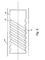
- the liner 52 is formed with a plurality of similar circumferential grooves 54 that are angled to the flow direction to create patterned cooling which "follows" the hot-side heat load.
- the concave surfaces of the grooves face the flow sleeve 56.
- the semi-circular grooves are based on a diameter D, and have a depth equal to about 0.05 to 0.50D, with a center-to-center distance between adjacent grooves of about 1.5-4D.
- the depth of the grooves in a single liner may vary within the stated range.
- grooves act to disrupt the flow on the liner surface in a manner that enhances heat transfer, but with a much lower pressure loss than raised turbulators. Specifically, the cooling flow enters the grooves and forms vortices which then interact with the mainstream flow for heat transfer enhancement.
- Figure 6 illustrates, schematically, another embodiment of the invention where circumferential grooves 58 are formed in the combustor liner 60 facing the flow sleeve 62, but patterned to induce additional circumferential effects of thermal enhancement.
- the grooves 58 are essentially formed by circumferentially overlapped, generally circular or oval concavities 64 with the concavities radially facing the flow sleeve 62. These patterned grooves could also be angled as in Figure 5.
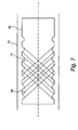
- circumferential grooves 66 are formed in the combustor liner 68, facing the flow sleeve 70 are angled (i.e., at an acute angle relative to a center axis of the combustor liner) in one direction along the length of the liner, while similar grooves 72 are angled in the opposite direction, thus creating a criss-cross pattern of "inverted turbulators" to induce additional global effects of thermal enhancement.
- the criss-crossed grooves 66, 72 may be of uniform cross-section (as shown), or patterned as in Figure 6.
Abstract
Description
- This invention relates generally to turbine components and more particularly to a combustor liner that surrounds the combustor in land based gas turbines.
- Traditional gas turbine combustors use diffusion (i.e., non-premixed) flames in which fuel and air enter the combustion chamber separately. The process of mixing and burning produces flame temperatures exceeding 3900 degrees F. Since conventional combustors and/or transition pieces having liners are generally capable of withstanding for about ten thousand hours (10,000), a maximum temperature on the order of only about 1500 degrees F., steps to protect the combustor and/or transition piece must be taken. This has typically been done by film-cooling which involves introducing relatively cool compressor air into a plenum formed by the combustor liner surrounding the outside of the combustor. In this prior arrangement, the air from the plenum passes through louvers in the combustor liner and then passes as a film over the inner surface of the liner, thereby maintaining combustor liner integrity.
- Because diatomic nitrogen rapidly disassociates at temperatures exceeding about 3000°F. (about 1650°C.), the high temperatures of diffusion combustion result in relatively large NOx emissions. One approach to reducing NOx emissions has been premix the maximum possible amount of compressor air with fuel. The resulting lean premixed combustion produces cooler flame temperatures and thus lower NOx emissions. Although lean premixed combustion is cooler than diffusion combustion, the flame temperature is still too hot for prior conventional combustor components to withstand.
- Furthermore, because the advanced combustors premix the maximum possible amount of air with the fuel for NOx reduction, little or no cooling air is available, making film-cooling of the combustor liner and transition piece premature at best. Nevertheless, combustor liners require active cooling to maintain material temperatures below limits. In dry low NOx (DLN) emission systems, this cooling can only be supplied as cold side convection. Such cooling must be performed within the requirements of thermal gradients and pressure loss. Thus, means such as thermal barrier coatings in conjunction with "backside" cooling have been considered to protect the combustor liner and transition piece from destruction by such high heat. Backside cooling involved passing the compressor air over the outer surface of the combustor liner and transition piece prior to premixing the air with the fuel.
- With respect to the combustor liner, the current practice is to impingement cool the liner, or to provide turbulators on the exterior surface of the liner. Another more recent practice is to provide an array of concavities on the exterior or outside surface of the liner (see U.S. Patent No. 6,098,397). The various known techniques enhance heat transfer but with varying effects on thermal gradients and pressure losses.
- There remains a need for enhanced levels of cooling with minimal pressure losses and for a capability to arrange enhancements as required locally.
- This invention provides convectively cooled combustor liner with cold side (i.e., outside) surface features that result in reduced pressure loss.
- In the exemplary embodiment of this invention, grooves of a semi-circular or near semi-circular cross-section are formed in the cold side of the combustor liner, each groove being continuous or in discrete segments about the circumference of the liner. In one arrangement, the grooves are arranged transverse to the cooling flow direction, and thus appear as inverted or recessed continuous turbulators. These grooves act to disrupt the flow on the liner surface in a manner that enhances heat transfer, but with a much lower pressure loss than raised turbulators.
- The turbulator grooves may also be angled to the flow direction to create patterned cooling which "follows" the hot side seat load. For example, in a premixed combustion can-annular system with significant hot gas swirl velocity, the hot side heat load is patterned according to the swirl strength and the location of the combustor nozzles.
- The grooves are preferably circular or near circular in cross-section so that they do not present the same flow separation and bluff body effect of raised turbulators. The grooves must also be of sufficient depth and width to allow cooling flow to enter and form vortices, which then interact with the mainstream flow for heat transfer enhancement. The grooves may be patterned and/or also be cris-crossed to generate additional heat transfer enhancement.
- Accordingly, in its broader aspects, the invention relates to a combustor liner for a gas turbine, the combustor liner having a substantially cylindrical shape; and a plurality of axially spaced circumferential grooves formed in an outside surface of the combustor liner.
- In another aspect, the invention relates to a combustor liner for a gas turbine, the combustor liner having a substantially cylindrical shape; and a plurality of axially spaced circumferential grooves formed in an outside surface of the combustor liner; wherein the grooves are circular in cross-section, and have a diameter D, and wherein a depth of the grooves is equal to about 0.05 to 0.50D.
- The invention will now be described in detail in conjunction with the following drawings, in which:
- FIGURE 1 is a schematic representation of a known gas turbine combustor;
- FIGURE 2 is a schematic view of a cylindrical combustor liner with turbulators;
- FIGURE 3 is a schematic view of a known cylindrical combustor liner with an array of concavities on the exterior surface thereof;
- FIGURE 4 is a schematic side elevation view of a cylindrical combustor liner with annular concave grooves in accordance with the invention:
- FIGURE 5 is a schematic side elevation of a cylindrical combustor liner with angled annular concave grooves in accordance with another embodiment of the invention;
- FIGURE 6 is a schematic side elevation of a cylindrical combustor with annular patterned grooves in accordance with still another embodiment of the invention; and
- FIGURE 7 is a schematic side elevation of a cylindrical combustor with annular criss-crossed grooves in accordance with still another embodiment of the invention.
- Figure 1 schematically illustrates a typical can annular reverse-
flow combustor 10 driven by the combustion gases from a fuel where a flowing medium with a high energy content, i.e., the combustion gases, produces a rotary motion as a result of being deflected by rings of blading mounted on a rotor. In operation, discharge air from the compressor 12 (compressed to a pressure on the order of about 250-400 Ib/in2) reverses direction as it passes over the outside of the combustors (one shown at 14) and again as it enters the combustor en route to the turbine (first stage indicated at 16). Compressed air and fuel are burned in thecombustion chamber 18, producing gases with a temperature of about 1500° C. or about 2730° F. These combustion gases flow at a high velocity intoturbine section 16 viatransition piece 20. The transition piece connects to thecombustor liner 24 at 22, but in some applications, a discrete connector segment may be located between thetransition piece 20 and the combustor liner. - In the construction of combustors and transition pieces, where the temperature of the combustion gases is about or exceeds about 1500° C., there are known materials which can survive such a high intensity heat environment without some form of cooling, but only for limited periods of time. Such materials are also expensive.
- Figure 2 shows in schematic form a generally
cylindrical combustor liner 24 of conventional construction, forming acombustion chamber 25. - In the exemplary embodiment illustrated, the
combustor liner 24 has acombustor head end 26 to which the combustors (not shown) are attached, and an opposite or forward end to which a double-walled transition piece 28 is attached. Other arrangements, including single-walled transition pieces, are included within the scope of the invention. Theliner 24 is provided with a plurality of upstanding, annular (or part-annular) ribs orturbulators 30 in a region adjacent thehead end 26. Acylindrical flow sleeve 32 surrounds the combustor liner in radially spaced relationship, forming aplenum 34 between the liner and flow sleeve that communicates with aplenum 36 formed by the double-walled construction of thetransition piece 28.Impingement cooling holes 38 are provided in theflow sleeve 32 in a region axially between thetransition piece 28 and theturbulators 30 in theliner 24. - Figure 3 illustrates in schematic form another known heat enhancement technique. In this instance, the
exterior surface 40 of thecombustor liner 42 is formed over an extended area thereof with a plurality of circular concavities ordimples 44. - Turning to Figure 4, a combustor liner 45 in accordance with an exemplary embodiment of this invention is formed with a plurality of "inverted turbulators" 48. These "inverted turbulators" 48 comprise individual, annular concave rings or circumferential grooves, spaced axially along the length of the
liner 46 with the concave surface facing radially outwardly toward theflow sleeve 50. - In Figure 5, the
liner 52 is formed with a plurality of similarcircumferential grooves 54 that are angled to the flow direction to create patterned cooling which "follows" the hot-side heat load. Here again, the concave surfaces of the grooves face theflow sleeve 56. - For the arrangements shown in Figures 4 and 5, the semi-circular grooves are based on a diameter D, and have a depth equal to about 0.05 to 0.50D, with a center-to-center distance between adjacent grooves of about 1.5-4D. The depth of the grooves in a single liner may vary within the stated range.
- These grooves act to disrupt the flow on the liner surface in a manner that enhances heat transfer, but with a much lower pressure loss than raised turbulators. Specifically, the cooling flow enters the grooves and forms vortices which then interact with the mainstream flow for heat transfer enhancement.
- Figure 6 illustrates, schematically, another embodiment of the invention where
circumferential grooves 58 are formed in thecombustor liner 60 facing theflow sleeve 62, but patterned to induce additional circumferential effects of thermal enhancement. Specifically, thegrooves 58 are essentially formed by circumferentially overlapped, generally circular oroval concavities 64 with the concavities radially facing theflow sleeve 62. These patterned grooves could also be angled as in Figure 5. - In Figure 7, concave,
circumferential grooves 66 are formed in thecombustor liner 68, facing theflow sleeve 70 are angled (i.e., at an acute angle relative to a center axis of the combustor liner) in one direction along the length of the liner, whilesimilar grooves 72 are angled in the opposite direction, thus creating a criss-cross pattern of "inverted turbulators" to induce additional global effects of thermal enhancement. The criss-crossedgrooves
Claims (8)
- A combustor liner (46) for a gas turbine, the combustor liner having a substantially cylindrical shape; and a plurality of axially spaced circumferential grooves (48) formed in an outside surface of said combustor liner.
- The combustor liner of claim 1 wherein said grooves (48) are substantially semi-circular in cross-section.
- The combustor liner of claim 2 wherein said grooves (48) have a diameter D, and wherein a depth of said grooves is equal to about 0.05 to 0.50D.
- The combustor liner of any one of claims 1 to 3 wherein said grooves have a diameter D, and a center-to-center distance between adjacent grooves (48) is equal to about 1.5-4D.
- The combustor liner of any one of claims 1 to 4 wherein said grooves (48) are arranged transversely to a direction of cooling air flow.
- The combustor liner of any one of claims 1 to 4 wherein said grooves (54) are angled relative to a direction of cooling air.
- The combustor liner (68) of claim 6 including a second plurality of circumferential grooves (72) criss-crossed with said first plurality of circumferential grooves (66).
- The combustor liner of claim 1 wherein said grooves (58) are each comprised of overlapping circular concavities (64).
Applications Claiming Priority (2)
| Application Number | Priority Date | Filing Date | Title |
|---|---|---|---|
| US65495 | 2002-10-24 | ||
| US10/065,495 US7104067B2 (en) | 2002-10-24 | 2002-10-24 | Combustor liner with inverted turbulators |
Publications (3)
| Publication Number | Publication Date |
|---|---|
| EP1413829A2 true EP1413829A2 (en) | 2004-04-28 |
| EP1413829A3 EP1413829A3 (en) | 2006-10-18 |
| EP1413829B1 EP1413829B1 (en) | 2014-05-21 |
Family
ID=32067702
Family Applications (1)
| Application Number | Title | Priority Date | Filing Date |
|---|---|---|---|
| EP03256700.0A Expired - Lifetime EP1413829B1 (en) | 2002-10-24 | 2003-10-23 | Combustor liner with inverted turbulators |
Country Status (4)
| Country | Link |
|---|---|
| US (1) | US7104067B2 (en) |
| EP (1) | EP1413829B1 (en) |
| JP (1) | JP4498720B2 (en) |
| KR (1) | KR100825143B1 (en) |
Cited By (2)
| Publication number | Priority date | Publication date | Assignee | Title |
|---|---|---|---|---|
| EP1850070A2 (en) * | 2006-04-24 | 2007-10-31 | General Electric Company | Methods and system for reducing pressure losses in gas turbine engines |
| EP2199681A1 (en) * | 2008-12-18 | 2010-06-23 | Siemens Aktiengesellschaft | Gas turbine combustion chamber and gas turbine |
Families Citing this family (55)
| Publication number | Priority date | Publication date | Assignee | Title |
|---|---|---|---|---|
| US7010921B2 (en) * | 2004-06-01 | 2006-03-14 | General Electric Company | Method and apparatus for cooling combustor liner and transition piece of a gas turbine |
| US7574865B2 (en) * | 2004-11-18 | 2009-08-18 | Siemens Energy, Inc. | Combustor flow sleeve with optimized cooling and airflow distribution |
| US7360364B2 (en) * | 2004-12-17 | 2008-04-22 | General Electric Company | Method and apparatus for assembling gas turbine engine combustors |
| US7386980B2 (en) * | 2005-02-02 | 2008-06-17 | Power Systems Mfg., Llc | Combustion liner with enhanced heat transfer |
| US7464537B2 (en) * | 2005-04-04 | 2008-12-16 | United Technologies Corporation | Heat transfer enhancement features for a tubular wall combustion chamber |
| US7810336B2 (en) * | 2005-06-03 | 2010-10-12 | Siemens Energy, Inc. | System for introducing fuel to a fluid flow upstream of a combustion area |
| US7726114B2 (en) * | 2005-12-07 | 2010-06-01 | General Electric Company | Integrated combustor-heat exchanger and systems for power generation using the same |
| US20070137172A1 (en) * | 2005-12-16 | 2007-06-21 | General Electric Company | Geometric configuration and confinement for deflagration to detonation transition enhancement |
| US7669405B2 (en) * | 2005-12-22 | 2010-03-02 | General Electric Company | Shaped walls for enhancement of deflagration-to-detonation transition |
| US7540153B2 (en) * | 2006-02-27 | 2009-06-02 | Mitsubishi Heavy Industries Ltd. | Combustor |
| US7762070B2 (en) * | 2006-05-11 | 2010-07-27 | Siemens Energy, Inc. | Pilot nozzle heat shield having internal turbulators |
| US7743821B2 (en) | 2006-07-26 | 2010-06-29 | General Electric Company | Air cooled heat exchanger with enhanced heat transfer coefficient fins |
| US20080078534A1 (en) * | 2006-10-02 | 2008-04-03 | General Electric Company | Heat exchanger tube with enhanced heat transfer co-efficient and related method |
| US20080078535A1 (en) * | 2006-10-03 | 2008-04-03 | General Electric Company | Heat exchanger tube with enhanced heat transfer co-efficient and related method |
| US20080104961A1 (en) * | 2006-11-08 | 2008-05-08 | Ronald Scott Bunker | Method and apparatus for enhanced mixing in premixing devices |
| US7967559B2 (en) * | 2007-05-30 | 2011-06-28 | General Electric Company | Stator-rotor assembly having surface feature for enhanced containment of gas flow and related processes |
| US8376706B2 (en) * | 2007-09-28 | 2013-02-19 | General Electric Company | Turbine airfoil concave cooling passage using dual-swirl flow mechanism and method |
| US20090145132A1 (en) * | 2007-12-07 | 2009-06-11 | General Electric Company | Methods and system for reducing pressure losses in gas turbine engines |
| CN101981381A (en) * | 2008-03-31 | 2011-02-23 | 川崎重工业株式会社 | Cooling structure for gas turbine combustor |
| US8245514B2 (en) * | 2008-07-10 | 2012-08-21 | United Technologies Corporation | Combustion liner for a gas turbine engine including heat transfer columns to increase cooling of a hula seal at the transition duct region |
| US20100011770A1 (en) * | 2008-07-21 | 2010-01-21 | Ronald James Chila | Gas Turbine Premixer with Cratered Fuel Injection Sites |
| US20100205972A1 (en) | 2009-02-17 | 2010-08-19 | General Electric Company | One-piece can combustor with heat transfer surface enhacements |
| US20100223931A1 (en) * | 2009-03-04 | 2010-09-09 | General Electric Company | Pattern cooled combustor liner |
| US8307657B2 (en) * | 2009-03-10 | 2012-11-13 | General Electric Company | Combustor liner cooling system |
| US20100269513A1 (en) * | 2009-04-23 | 2010-10-28 | General Electric Company | Thimble Fan for a Combustion System |
| US8307654B1 (en) * | 2009-09-21 | 2012-11-13 | Florida Turbine Technologies, Inc. | Transition duct with spiral finned cooling passage |
| US8402764B1 (en) * | 2009-09-21 | 2013-03-26 | Florida Turbine Technologies, Inc. | Transition duct with spiral cooling channels |
| US8590314B2 (en) | 2010-04-09 | 2013-11-26 | General Electric Company | Combustor liner helical cooling apparatus |
| US9376960B2 (en) * | 2010-07-23 | 2016-06-28 | University Of Central Florida Research Foundation, Inc. | Heat transfer augmented fluid flow surfaces |
| US8201412B2 (en) * | 2010-09-13 | 2012-06-19 | General Electric Company | Apparatus and method for cooling a combustor |
| US20120208141A1 (en) * | 2011-02-14 | 2012-08-16 | General Electric Company | Combustor |
| US8955330B2 (en) | 2011-03-29 | 2015-02-17 | Siemens Energy, Inc. | Turbine combustion system liner |
| US8915087B2 (en) | 2011-06-21 | 2014-12-23 | General Electric Company | Methods and systems for transferring heat from a transition nozzle |
| US8966910B2 (en) | 2011-06-21 | 2015-03-03 | General Electric Company | Methods and systems for cooling a transition nozzle |
| US20130022444A1 (en) * | 2011-07-19 | 2013-01-24 | Sudhakar Neeli | Low pressure turbine exhaust diffuser with turbulators |
| US8745988B2 (en) | 2011-09-06 | 2014-06-10 | Pratt & Whitney Canada Corp. | Pin fin arrangement for heat shield of gas turbine engine |
| US20130180252A1 (en) * | 2012-01-18 | 2013-07-18 | General Electric Company | Combustor assembly with impingement sleeve holes and turbulators |
| US9709277B2 (en) * | 2012-05-15 | 2017-07-18 | General Electric Company | Fuel plenum premixing tube with surface treatment |
| US20130318986A1 (en) * | 2012-06-05 | 2013-12-05 | General Electric Company | Impingement cooled combustor |
| WO2014137687A1 (en) * | 2013-03-05 | 2014-09-12 | United Technologies Corporation | Gas turbine engine component external surface micro-channel cooling |
| EP3055537B1 (en) * | 2013-10-07 | 2020-08-19 | United Technologies Corporation | Combustor wall with tapered cooling cavity |
| EP2949871B1 (en) * | 2014-05-07 | 2017-03-01 | United Technologies Corporation | Variable vane segment |
| US9989255B2 (en) | 2014-07-25 | 2018-06-05 | General Electric Company | Liner assembly and method of turbulator fabrication |
| US20160201476A1 (en) * | 2014-10-31 | 2016-07-14 | General Electric Company | Airfoil for a turbine engine |
| US10228135B2 (en) | 2016-03-15 | 2019-03-12 | General Electric Company | Combustion liner cooling |
| EP3225914A1 (en) * | 2016-03-31 | 2017-10-04 | Siemens Aktiengesellschaft | Turbomachine component with a corrugated cooled wall and a method of manufacturing |
| US20170314412A1 (en) * | 2016-05-02 | 2017-11-02 | General Electric Company | Dimpled Naccelle Inner Surface for Heat Transfer Improvement |
| US10443854B2 (en) * | 2016-06-21 | 2019-10-15 | General Electric Company | Pilot premix nozzle and fuel nozzle assembly |
| KR101863779B1 (en) * | 2017-09-15 | 2018-06-01 | 두산중공업 주식회사 | Helicoidal structure for enhancing cooling performance of liner and a gas turbine combustor using the same |
| KR102099307B1 (en) * | 2017-10-11 | 2020-04-09 | 두산중공업 주식회사 | Turbulence generating structure for enhancing cooling performance of liner and a gas turbine combustor using the same |
| US20190203940A1 (en) * | 2018-01-03 | 2019-07-04 | General Electric Company | Combustor Assembly for a Turbine Engine |
| US11306918B2 (en) * | 2018-11-02 | 2022-04-19 | Chromalloy Gas Turbine Llc | Turbulator geometry for a combustion liner |
| CN113091091A (en) * | 2021-05-13 | 2021-07-09 | 中国联合重型燃气轮机技术有限公司 | Combustion chamber laminate and combustion chamber |
| KR102537897B1 (en) * | 2021-08-11 | 2023-05-31 | 한국전력공사 | Nozzle Structure for Improved Mixing ratio of Combustor |
| US11828226B2 (en) * | 2022-04-13 | 2023-11-28 | General Electric Company | Compressor bleed air channels having a pattern of vortex generators |
Citations (1)
| Publication number | Priority date | Publication date | Assignee | Title |
|---|---|---|---|---|
| US6098397A (en) | 1998-06-08 | 2000-08-08 | Caterpillar Inc. | Combustor for a low-emissions gas turbine engine |
Family Cites Families (80)
| Publication number | Priority date | Publication date | Assignee | Title |
|---|---|---|---|---|
| US710130A (en) * | 1899-05-09 | 1902-09-30 | Carl W Weiss | Regenerator-burner. |
| US1848375A (en) * | 1929-04-27 | 1932-03-08 | Wellington W Muir | Radiator core for automobile cooling systems |
| GB636811A (en) * | 1948-05-05 | 1950-05-10 | Lucas Ltd Joseph | Improvements relating to combustion chambers for prime movers |
| US2672728A (en) * | 1951-05-23 | 1954-03-23 | Westinghouse Electric Corp | Reinforced combustion chamber construction |
| US2801073A (en) * | 1952-06-30 | 1957-07-30 | United Aircraft Corp | Hollow sheet metal blade or vane construction |
| US2938333A (en) * | 1957-03-18 | 1960-05-31 | Gen Motors Corp | Combustion chamber liner construction |
| US3229763A (en) * | 1963-07-16 | 1966-01-18 | Rosenblad Corp | Flexible plate heat exchangers with variable spacing |
| GB1074785A (en) * | 1965-04-08 | 1967-07-05 | Rolls Royce | Combustion apparatus e.g. for a gas turbine engine |
| US3344834A (en) * | 1965-05-26 | 1967-10-03 | United States Steel Corp | Apparatus for partial combustion of hydrocarbon fuels |
| US3572031A (en) * | 1969-07-11 | 1971-03-23 | United Aircraft Corp | Variable area cooling passages for gas turbine burners |
| US3664928A (en) * | 1969-12-15 | 1972-05-23 | Aerojet General Co | Dimpled heat transfer walls for distillation apparatus |
| US4480436A (en) * | 1972-12-19 | 1984-11-06 | General Electric Company | Combustion chamber construction |
| US3899882A (en) * | 1974-03-27 | 1975-08-19 | Westinghouse Electric Corp | Gas turbine combustor basket cooling |
| US4184326A (en) * | 1975-12-05 | 1980-01-22 | United Technologies Corporation | Louver construction for liner of gas turbine engine combustor |
| US4158949A (en) * | 1977-11-25 | 1979-06-26 | General Motors Corporation | Segmented annular combustor |
| US4236378A (en) * | 1978-03-01 | 1980-12-02 | General Electric Company | Sectoral combustor for burning low-BTU fuel gas |
| US4259842A (en) * | 1978-12-11 | 1981-04-07 | General Electric Company | Combustor liner slot with cooled props |
| US4380906A (en) * | 1981-01-22 | 1983-04-26 | United Technologies Corporation | Combustion liner cooling scheme |
| US4655044A (en) * | 1983-12-21 | 1987-04-07 | United Technologies Corporation | Coated high temperature combustor liner |
| JPH06100432B2 (en) * | 1984-06-20 | 1994-12-12 | 株式会社日立製作所 | Heat transfer tube |
| JPS6189497A (en) * | 1984-10-05 | 1986-05-07 | Hitachi Ltd | Heat transfer pipe |
| US4597258A (en) * | 1984-11-26 | 1986-07-01 | United Technologies Corporation | Combustor mount |
| US4686823A (en) * | 1986-04-28 | 1987-08-18 | United Technologies Corporation | Sliding joint for an annular combustor |
| JP2590099B2 (en) | 1987-05-13 | 1997-03-12 | 株式会社日立製作所 | Character reading method |
| US4838031A (en) * | 1987-08-06 | 1989-06-13 | Avco Corporation | Internally cooled combustion chamber liner |
| US5024058A (en) * | 1989-12-08 | 1991-06-18 | Sundstrand Corporation | Hot gas generator |
| US5405242A (en) * | 1990-07-09 | 1995-04-11 | United Technologies Corporation | Cooled vane |
| US5695321A (en) * | 1991-12-17 | 1997-12-09 | General Electric Company | Turbine blade having variable configuration turbulators |
| US5681144A (en) * | 1991-12-17 | 1997-10-28 | General Electric Company | Turbine blade having offset turbulators |
| US5353865A (en) | 1992-03-30 | 1994-10-11 | General Electric Company | Enhanced impingement cooled components |
| US5660525A (en) * | 1992-10-29 | 1997-08-26 | General Electric Company | Film cooled slotted wall |
| US5651662A (en) * | 1992-10-29 | 1997-07-29 | General Electric Company | Film cooled wall |
| US5361828A (en) * | 1993-02-17 | 1994-11-08 | General Electric Company | Scaled heat transfer surface with protruding ramp surface turbulators |
| US5577555A (en) * | 1993-02-24 | 1996-11-26 | Hitachi, Ltd. | Heat exchanger |
| US5327727A (en) * | 1993-04-05 | 1994-07-12 | General Electric Company | Micro-grooved heat transfer combustor wall |
| US5363654A (en) * | 1993-05-10 | 1994-11-15 | General Electric Company | Recuperative impingement cooling of jet engine components |
| US5460002A (en) * | 1993-05-21 | 1995-10-24 | General Electric Company | Catalytically-and aerodynamically-assisted liner for gas turbine combustors |
| US5353965A (en) * | 1993-11-01 | 1994-10-11 | Lee Gary K | Container for dispensing condiments |
| US5392596A (en) * | 1993-12-21 | 1995-02-28 | Solar Turbines Incorporated | Combustor assembly construction |
| JPH07190365A (en) * | 1993-12-27 | 1995-07-28 | Toshiba Corp | Gas-turbine combustor |
| JPH08110012A (en) | 1994-10-07 | 1996-04-30 | Hitachi Ltd | Manufacturing method of combustor liner |
| US5421158A (en) * | 1994-10-21 | 1995-06-06 | General Electric Company | Segmented centerbody for a double annular combustor |
| JPH08254316A (en) * | 1995-03-16 | 1996-10-01 | Toshiba Corp | Liner for gas turbine combustor and manufacture thereof |
| US5758503A (en) * | 1995-05-03 | 1998-06-02 | United Technologies Corporation | Gas turbine combustor |
| JPH09196377A (en) * | 1996-01-12 | 1997-07-29 | Hitachi Ltd | Gas turbine combustor |
| JP3297838B2 (en) | 1996-02-09 | 2002-07-02 | 株式会社日立製作所 | Heat transfer tube and method of manufacturing the same |
| US5724816A (en) * | 1996-04-10 | 1998-03-10 | General Electric Company | Combustor for a gas turbine with cooling structure |
| US6026801A (en) * | 1996-04-30 | 2000-02-22 | Barkan; Kenneth C. | Plug core heat exchanger |
| US5822853A (en) * | 1996-06-24 | 1998-10-20 | General Electric Company | Method for making cylindrical structures with cooling channels |
| US5933699A (en) * | 1996-06-24 | 1999-08-03 | General Electric Company | Method of making double-walled turbine components from pre-consolidated assemblies |
| US5975850A (en) * | 1996-12-23 | 1999-11-02 | General Electric Company | Turbulated cooling passages for turbine blades |
| US5738493A (en) * | 1997-01-03 | 1998-04-14 | General Electric Company | Turbulator configuration for cooling passages of an airfoil in a gas turbine engine |
| US5797726A (en) * | 1997-01-03 | 1998-08-25 | General Electric Company | Turbulator configuration for cooling passages or rotor blade in a gas turbine engine |
| WO1999006771A1 (en) * | 1997-07-31 | 1999-02-11 | Alliedsignal Inc. | Rib turbulators for combustor external cooling |
| GB2328011A (en) * | 1997-08-05 | 1999-02-10 | Europ Gas Turbines Ltd | Combustor for gas or liquid fuelled turbine |
| US6237344B1 (en) * | 1998-07-20 | 2001-05-29 | General Electric Company | Dimpled impingement baffle |
| US6314716B1 (en) * | 1998-12-18 | 2001-11-13 | Solar Turbines Incorporated | Serial cooling of a combustor for a gas turbine engine |
| US6142734A (en) * | 1999-04-06 | 2000-11-07 | General Electric Company | Internally grooved turbine wall |
| US6468669B1 (en) * | 1999-05-03 | 2002-10-22 | General Electric Company | Article having turbulation and method of providing turbulation on an article |
| US6190120B1 (en) * | 1999-05-14 | 2001-02-20 | General Electric Co. | Partially turbulated trailing edge cooling passages for gas turbine nozzles |
| US6589600B1 (en) * | 1999-06-30 | 2003-07-08 | General Electric Company | Turbine engine component having enhanced heat transfer characteristics and method for forming same |
| US6494044B1 (en) * | 1999-11-19 | 2002-12-17 | General Electric Company | Aerodynamic devices for enhancing sidepanel cooling on an impingement cooled transition duct and related method |
| JP2001183687A (en) * | 1999-12-22 | 2001-07-06 | Hitachi Ltd | Liquid crystal display device |
| US6412268B1 (en) * | 2000-04-06 | 2002-07-02 | General Electric Company | Cooling air recycling for gas turbine transition duct end frame and related method |
| US6334310B1 (en) * | 2000-06-02 | 2002-01-01 | General Electric Company | Fracture resistant support structure for a hula seal in a turbine combustor and related method |
| DE10127084B4 (en) | 2000-06-17 | 2019-05-29 | Mahle International Gmbh | Heat exchanger, in particular for motor vehicles |
| WO2003093664A1 (en) * | 2000-06-28 | 2003-11-13 | Power Systems Mfg. Llc | Combustion chamber/venturi cooling for a low nox emission combustor |
| US6446438B1 (en) * | 2000-06-28 | 2002-09-10 | Power Systems Mfg., Llc | Combustion chamber/venturi cooling for a low NOx emission combustor |
| US6402464B1 (en) * | 2000-08-29 | 2002-06-11 | General Electric Company | Enhanced heat transfer surface for cast-in-bump-covered cooling surfaces and methods of enhancing heat transfer |
| US6408629B1 (en) * | 2000-10-03 | 2002-06-25 | General Electric Company | Combustor liner having preferentially angled cooling holes |
| US6504274B2 (en) * | 2001-01-04 | 2003-01-07 | General Electric Company | Generator stator cooling design with concavity surfaces |
| US6526756B2 (en) * | 2001-02-14 | 2003-03-04 | General Electric Company | Method and apparatus for enhancing heat transfer in a combustor liner for a gas turbine |
| EP1255079A1 (en) * | 2001-04-30 | 2002-11-06 | ALSTOM (Switzerland) Ltd | Catalyst |
| US6530225B1 (en) * | 2001-09-21 | 2003-03-11 | Honeywell International, Inc. | Waffle cooling |
| US6610385B2 (en) * | 2001-12-20 | 2003-08-26 | General Electric Company | Integral surface features for CMC components and method therefor |
| JP2003328775A (en) * | 2002-05-16 | 2003-11-19 | Mitsubishi Heavy Ind Ltd | Combustor for gas turbine |
| US6772595B2 (en) * | 2002-06-25 | 2004-08-10 | Power Systems Mfg., Llc | Advanced cooling configuration for a low emissions combustor venturi |
| US6722134B2 (en) * | 2002-09-18 | 2004-04-20 | General Electric Company | Linear surface concavity enhancement |
| US6986253B2 (en) * | 2003-07-16 | 2006-01-17 | General Electric Company | Methods and apparatus for cooling gas turbine engine combustors |
| US20050044857A1 (en) * | 2003-08-26 | 2005-03-03 | Boris Glezer | Combustor of a gas turbine engine |
-
2002
- 2002-10-24 US US10/065,495 patent/US7104067B2/en not_active Expired - Lifetime
-
2003
- 2003-10-23 EP EP03256700.0A patent/EP1413829B1/en not_active Expired - Lifetime
- 2003-10-23 JP JP2003362644A patent/JP4498720B2/en not_active Expired - Fee Related
- 2003-10-23 KR KR1020030074353A patent/KR100825143B1/en not_active IP Right Cessation
Patent Citations (1)
| Publication number | Priority date | Publication date | Assignee | Title |
|---|---|---|---|---|
| US6098397A (en) | 1998-06-08 | 2000-08-08 | Caterpillar Inc. | Combustor for a low-emissions gas turbine engine |
Cited By (4)
| Publication number | Priority date | Publication date | Assignee | Title |
|---|---|---|---|---|
| EP1850070A2 (en) * | 2006-04-24 | 2007-10-31 | General Electric Company | Methods and system for reducing pressure losses in gas turbine engines |
| EP1850070A3 (en) * | 2006-04-24 | 2014-08-06 | General Electric Company | Methods and system for reducing pressure losses in gas turbine engines |
| EP2199681A1 (en) * | 2008-12-18 | 2010-06-23 | Siemens Aktiengesellschaft | Gas turbine combustion chamber and gas turbine |
| WO2010069663A1 (en) * | 2008-12-18 | 2010-06-24 | Siemens Aktiengesellschaft | Gas turbine combustion chamber and gas turbine |
Also Published As
| Publication number | Publication date |
|---|---|
| KR20040036629A (en) | 2004-04-30 |
| JP4498720B2 (en) | 2010-07-07 |
| US20040079082A1 (en) | 2004-04-29 |
| JP2004144469A (en) | 2004-05-20 |
| KR100825143B1 (en) | 2008-04-24 |
| EP1413829B1 (en) | 2014-05-21 |
| EP1413829A3 (en) | 2006-10-18 |
| US7104067B2 (en) | 2006-09-12 |
Similar Documents
| Publication | Publication Date | Title |
|---|---|---|
| EP1413829B1 (en) | Combustor liner with inverted turbulators | |
| US6681578B1 (en) | Combustor liner with ring turbulators and related method | |
| US6761031B2 (en) | Double wall combustor liner segment with enhanced cooling | |
| US7373778B2 (en) | Combustor cooling with angled segmented surfaces | |
| US8544277B2 (en) | Turbulated aft-end liner assembly and cooling method | |
| CA2546881C (en) | Gas turbine engine combustor with improved cooling | |
| US20090120093A1 (en) | Turbulated aft-end liner assembly and cooling method | |
| EP0378505B1 (en) | Combustor fuel nozzle arrangement | |
| US7010921B2 (en) | Method and apparatus for cooling combustor liner and transition piece of a gas turbine | |
| US5497611A (en) | Process for the cooling of an auto-ignition combustion chamber | |
| US7624577B2 (en) | Gas turbine engine combustor with improved cooling | |
| EP1195559A2 (en) | Combustor liner having cooling holes with different orientations | |
| EP2532962A2 (en) | Combustion liner having turbulators | |
| EP2211105A2 (en) | Turbulated combustor aft-end liner assembly and related cooling method | |
| US20100223931A1 (en) | Pattern cooled combustor liner | |
| EP1286117A1 (en) | Preferential multihole combustor liner | |
| EP3447381B1 (en) | Cooling path structure for concentrated cooling of seal area and gas turbine combustor having the same | |
| EP1426558A2 (en) | Gas turbine transition piece with dimpled surface and cooling method for such a transition piece | |
| EP2230456A2 (en) | Combustion liner with mixing hole stub | |
| US9181812B1 (en) | Can-annular combustor with premixed tangential fuel-air nozzles for use on gas turbine engines | |
| US7926279B2 (en) | Extended life fuel nozzle |
Legal Events
| Date | Code | Title | Description |
|---|---|---|---|
| PUAI | Public reference made under article 153(3) epc to a published international application that has entered the european phase |
Free format text: ORIGINAL CODE: 0009012 |
|
| AK | Designated contracting states |
Kind code of ref document: A2 Designated state(s): AT BE BG CH CY CZ DE DK EE ES FI FR GB GR HU IE IT LI LU MC NL PT RO SE SI SK TR |
|
| AX | Request for extension of the european patent |
Extension state: AL LT LV MK |
|
| PUAL | Search report despatched |
Free format text: ORIGINAL CODE: 0009013 |
|
| AK | Designated contracting states |
Kind code of ref document: A3 Designated state(s): AT BE BG CH CY CZ DE DK EE ES FI FR GB GR HU IE IT LI LU MC NL PT RO SE SI SK TR |
|
| AX | Request for extension of the european patent |
Extension state: AL LT LV MK |
|
| 17P | Request for examination filed |
Effective date: 20070418 |
|
| AKX | Designation fees paid |
Designated state(s): CH CZ FR GB IT LI SE |
|
| REG | Reference to a national code |
Ref country code: DE Ref legal event code: 8566 |
|
| 17Q | First examination report despatched |
Effective date: 20100623 |
|
| GRAP | Despatch of communication of intention to grant a patent |
Free format text: ORIGINAL CODE: EPIDOSNIGR1 |
|
| INTG | Intention to grant announced |
Effective date: 20140120 |
|
| GRAS | Grant fee paid |
Free format text: ORIGINAL CODE: EPIDOSNIGR3 |
|
| GRAA | (expected) grant |
Free format text: ORIGINAL CODE: 0009210 |
|
| AK | Designated contracting states |
Kind code of ref document: B1 Designated state(s): CH CZ FR GB IT LI SE |
|
| REG | Reference to a national code |
Ref country code: GB Ref legal event code: FG4D |
|
| REG | Reference to a national code |
Ref country code: CH Ref legal event code: EP |
|
| PG25 | Lapsed in a contracting state [announced via postgrant information from national office to epo] |
Ref country code: SE Free format text: LAPSE BECAUSE OF FAILURE TO SUBMIT A TRANSLATION OF THE DESCRIPTION OR TO PAY THE FEE WITHIN THE PRESCRIBED TIME-LIMIT Effective date: 20140521 |
|
| PG25 | Lapsed in a contracting state [announced via postgrant information from national office to epo] |
Ref country code: CZ Free format text: LAPSE BECAUSE OF FAILURE TO SUBMIT A TRANSLATION OF THE DESCRIPTION OR TO PAY THE FEE WITHIN THE PRESCRIBED TIME-LIMIT Effective date: 20140521 |
|
| PLBE | No opposition filed within time limit |
Free format text: ORIGINAL CODE: 0009261 |
|
| STAA | Information on the status of an ep patent application or granted ep patent |
Free format text: STATUS: NO OPPOSITION FILED WITHIN TIME LIMIT |
|
| 26N | No opposition filed |
Effective date: 20150224 |
|
| PG25 | Lapsed in a contracting state [announced via postgrant information from national office to epo] |
Ref country code: IT Free format text: LAPSE BECAUSE OF FAILURE TO SUBMIT A TRANSLATION OF THE DESCRIPTION OR TO PAY THE FEE WITHIN THE PRESCRIBED TIME-LIMIT Effective date: 20140521 |
|
| REG | Reference to a national code |
Ref country code: FR Ref legal event code: PLFP Year of fee payment: 13 |
|
| REG | Reference to a national code |
Ref country code: FR Ref legal event code: PLFP Year of fee payment: 14 |
|
| PGFP | Annual fee paid to national office [announced via postgrant information from national office to epo] |
Ref country code: GB Payment date: 20161027 Year of fee payment: 14 Ref country code: CH Payment date: 20161027 Year of fee payment: 14 Ref country code: FR Payment date: 20161025 Year of fee payment: 14 |
|
| REG | Reference to a national code |
Ref country code: CH Ref legal event code: PL |
|
| GBPC | Gb: european patent ceased through non-payment of renewal fee |
Effective date: 20171023 |
|
| REG | Reference to a national code |
Ref country code: FR Ref legal event code: ST Effective date: 20180629 |
|
| PG25 | Lapsed in a contracting state [announced via postgrant information from national office to epo] |
Ref country code: GB Free format text: LAPSE BECAUSE OF NON-PAYMENT OF DUE FEES Effective date: 20171023 Ref country code: LI Free format text: LAPSE BECAUSE OF NON-PAYMENT OF DUE FEES Effective date: 20171031 Ref country code: CH Free format text: LAPSE BECAUSE OF NON-PAYMENT OF DUE FEES Effective date: 20171031 |
|
| PG25 | Lapsed in a contracting state [announced via postgrant information from national office to epo] |
Ref country code: FR Free format text: LAPSE BECAUSE OF NON-PAYMENT OF DUE FEES Effective date: 20171031 |