EP1413706A2 - Raising mechanism for a venetian blind - Google Patents
Raising mechanism for a venetian blind Download PDFInfo
- Publication number
- EP1413706A2 EP1413706A2 EP03255383A EP03255383A EP1413706A2 EP 1413706 A2 EP1413706 A2 EP 1413706A2 EP 03255383 A EP03255383 A EP 03255383A EP 03255383 A EP03255383 A EP 03255383A EP 1413706 A2 EP1413706 A2 EP 1413706A2
- Authority
- EP
- European Patent Office
- Prior art keywords
- venetian blind
- cord
- bottom bar
- attached
- bar
- Prior art date
- Legal status (The legal status is an assumption and is not a legal conclusion. Google has not performed a legal analysis and makes no representation as to the accuracy of the status listed.)
- Withdrawn
Links
Images
Classifications
-
- E—FIXED CONSTRUCTIONS
- E06—DOORS, WINDOWS, SHUTTERS, OR ROLLER BLINDS IN GENERAL; LADDERS
- E06B—FIXED OR MOVABLE CLOSURES FOR OPENINGS IN BUILDINGS, VEHICLES, FENCES OR LIKE ENCLOSURES IN GENERAL, e.g. DOORS, WINDOWS, BLINDS, GATES
- E06B9/00—Screening or protective devices for wall or similar openings, with or without operating or securing mechanisms; Closures of similar construction
- E06B9/24—Screens or other constructions affording protection against light, especially against sunshine; Similar screens for privacy or appearance; Slat blinds
- E06B9/26—Lamellar or like blinds, e.g. venetian blinds
- E06B9/28—Lamellar or like blinds, e.g. venetian blinds with horizontal lamellae, e.g. non-liftable
- E06B9/30—Lamellar or like blinds, e.g. venetian blinds with horizontal lamellae, e.g. non-liftable liftable
- E06B9/32—Operating, guiding, or securing devices therefor
Definitions
- This invention relates to a venetian blind, and especially to a raising mechanism for a venetian blind.
- Venetian blinds have a top and bottom bar.
- the top bar may be attached to the upper portion of a window frame, or similar mounting point.
- the bottom bar is suspended beneath the top bar using the pulling cords of the raising mechanisms.
- Horizontal slats are suspended between the top and bottom bar. By tilting the inclination angle of the horizontal slats the amount of light passing through the window may be adjusted. If desired, the venetian blind may also be raised to allow full access to the window.
- an operator may pull on a cord, or a number of cords bundled together. This action raises a bottom bar of the blind towards a top bar by drawing a cord towards the top bar.
- the horizontal slats gather on the bottom bar as the bottom bar contacts each slat, thus opening the blind.
- a venetian blind having a top bar, a bottom bar, horizontal slats disposed between said top and bottom bars, a raising mechanism for adjusting the height of a bottom bar of said venetian blind, wherein said raising mechanism comprises:
- the first and second member may be any element which allows cord to pass over the element, without undue frictional resistance.
- the cord is attached to the top bar of the blind assembly. Even more preferably the cord is attached adjacent to the first member attached to the top bar.
- the first member may be one of a plurality of like members attached to the top bar and the cord is fed past the members attached to the top bar.
- the second member may be one of a plurality of like members attached to the bottom bar, and the cord is fed past the members attached to the bottom bar.
- the members are rotatable members.
- the members rotate with the motion of the cord passing thereover.
- the members are pulleys.
- the venetian blind is provided with at least two raising mechanisms.
- the venetian blind is provided with a further member for receiving the cords of the raising mechanisms.
- the further member is a rotatable member.
- the further member rotates with the motion of the cords passing thereover.
- the further member is a pulley.
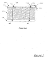
- Figure 1 depicts a conventional venetian blind assembly 150, having a top bar 121 and a bottom bar 120, horizontal slats 135, an aggregate cord 125 and raising mechanisms 130, 131.
- the raising mechanisms 130, 131 have a pulley 111, 113, and a pulling cords 160, 161 attached to bottom bar 120.
- the pulling cords 160, 161 both pass the secondary pulley 115, and form the aggregate cord 125.
- displacement of the aggregate cord 125 translates to equal displacement of the bottom bar 120.
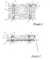
- Figure 2 depicts a blind assembly 50 with the bottom bar 20 in the lowest position.
- the top bar 21 of the blind assembly 50 may be attached above a window (not shown).
- Horizontal slats 35 are distributed between the bottom bar 20 and the top bar 21.
- Figure 3 depicts the blind assembly 50 in figure 2 in a partially open position, with the bottom bar 20 located between the highest position and the lowest position. As the bottom bar 20 is raised, the slats 35 are progressively gathered on the bottom bar 20. Thus the slats 35 are raised with the bottom bar 20.
- the aggregate cord 25 is made up of pulling cords 1 and 2, which are respectively associated with raising mechanisms 30 and 31. Both pulling cords 1, 2 are attached to the top bar 21 at the attachment points 5 and 6. The attachment points 5, 6 are located adjacent to the corresponding upper primary pulleys 11, 13. From attachment point 5, pulling cord 1 first passes around lower primary pulley 10, which is fixed to the bottom bar 20. Pulling cord 1 then passes around upper primary pulley 11 fixed to the top bar 21.
- pulling cord 2 first passes around lower primary pulley 12 fixed to the bottom bar 20 and then passes upper primary pulley 13 fixed to the top bar 21. Both pulling cords 1, 2 then pass around the secondary pulley 15, at which point aggregate cord 25 is formed.
- the pulling cords 1, 2 have a generally vertical orientation.
- the bottom bar 20 is suspended from the attachment points 5, 6 and the upper primary pulleys 11, 13.
- the suspended mass of the gathered slats and the bottom bar 20 is supported by four suspension points (the fixed points 5, 6 and the upper primary pulleys 11, 13).
- Pulling cords 1, 2 transfer the weight force of the suspended mass applied to the respective upper primary pulleys 11, 13 to the secondary pulley 15, and ultimately to aggregate cord 25.
- the force required on aggregate cord 25 to hold the blind in position is half the weight force of the suspended mass. Displacement of the aggregate cord 25 is greater than the displacement of the bottom bar 20.
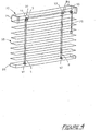
- FIG. 4 shows a blind assembly 50 with two raising mechanisms.
- the top bar 21 has upper primary pulleys 11, 13 which also provide attachment points 5, 6 for the pulling cords 1, 2.
- the secondary pulley 15 is attached near the end of the top bar 21, such that an operator may operate aggregate cord 25 remotely from the raising mechanisms.
Abstract
Description
- This invention relates to a venetian blind, and especially to a raising mechanism for a venetian blind.
- Venetian blinds have a top and bottom bar. The top bar may be attached to the upper portion of a window frame, or similar mounting point. The bottom bar is suspended beneath the top bar using the pulling cords of the raising mechanisms. Horizontal slats are suspended between the top and bottom bar. By tilting the inclination angle of the horizontal slats the amount of light passing through the window may be adjusted. If desired, the venetian blind may also be raised to allow full access to the window.
- To raise a blind, an operator may pull on a cord, or a number of cords bundled together. This action raises a bottom bar of the blind towards a top bar by drawing a cord towards the top bar. The horizontal slats gather on the bottom bar as the bottom bar contacts each slat, thus opening the blind.
- There is a problem with venetian blinds where the weight of blind assembly (ie. the bottom bar and the gathered slats) makes the operating effort overly demanding. This is especially a problem with wooden venetian blinds, which may weigh in excess of 10 kg.
- There is a need for a system which provides an operator with means to operate a venetian blind with ease.
- According to the invention, there is a provided a venetian blind having a top bar, a bottom bar, horizontal slats disposed between said top and bottom bars, a raising mechanism for adjusting the height of a bottom bar of said venetian blind, wherein said raising mechanism comprises:
- a first member attached to said top bar,
- a second member attached to said bottom bar, and
- a cord, which is attached at one end to said venetian blind and is fed past said first and second members,
- The first and second member may be any element which allows cord to pass over the element, without undue frictional resistance.
- Preferably, the cord is attached to the top bar of the blind assembly. Even more preferably the cord is attached adjacent to the first member attached to the top bar.
- Optionally, the first member may be one of a plurality of like members attached to the top bar and the cord is fed past the members attached to the top bar. In a further option, the second member may be one of a plurality of like members attached to the bottom bar, and the cord is fed past the members attached to the bottom bar.
- Preferably, the members are rotatable members. Thus, the members rotate with the motion of the cord passing thereover. Even more preferably, the members are pulleys.
- Preferably, the venetian blind is provided with at least two raising mechanisms.
- Preferably, the venetian blind is provided with a further member for receiving the cords of the raising mechanisms.
- Preferably, the further member is a rotatable member. Thus, the further member rotates with the motion of the cords passing thereover. Even more preferably, the further member is a pulley.
- In order that the present invention be more clearly ascertained, an embodiment will now be described, by way of example only, with reference to the accompanying drawings, in which:
- Figure 1
- is a schematic front view of a venetian blind of the prior art;
- Figure 2
- is a schematic front view of a venetian blind in accordance with an embodiment of the present invention with the blind in the lowest position;
- Figure 3
- is the venetian blind of figure 2, with the blind partially raised; and
- Figure 4
- is a schematic axonometric view of a venetian blind in accordance with another embodiment of the present invention with the blind in the lowest position.
- Figure 1 depicts a conventional venetian
blind assembly 150, having atop bar 121 and abottom bar 120,horizontal slats 135, anaggregate cord 125 and raisingmechanisms raising mechanisms pulley pulling cords bottom bar 120. Thepulling cords secondary pulley 115, and form theaggregate cord 125. In theraising mechanisms blind assembly 150, displacement of theaggregate cord 125 translates to equal displacement of thebottom bar 120. - Figure 2 depicts a
blind assembly 50 with thebottom bar 20 in the lowest position. Thetop bar 21 of theblind assembly 50 may be attached above a window (not shown).Horizontal slats 35 are distributed between thebottom bar 20 and thetop bar 21. By altering the length ofaggregate cord 25, the position of thebottom bar 20, and consequently theblind assembly 50, may be adjusted. - Figure 3 depicts the
blind assembly 50 in figure 2 in a partially open position, with thebottom bar 20 located between the highest position and the lowest position. As thebottom bar 20 is raised, theslats 35 are progressively gathered on thebottom bar 20. Thus theslats 35 are raised with thebottom bar 20. - The
aggregate cord 25 is made up ofpulling cords mechanisms pulling cords top bar 21 at theattachment points attachment points primary pulleys attachment point 5, pullingcord 1 first passes around lowerprimary pulley 10, which is fixed to thebottom bar 20. Pullingcord 1 then passes around upperprimary pulley 11 fixed to thetop bar 21. - Similarly, from
attachment point 6, pullingcord 2 first passes around lowerprimary pulley 12 fixed to thebottom bar 20 and then passes upperprimary pulley 13 fixed to thetop bar 21. Both pullingcords secondary pulley 15, at whichpoint aggregate cord 25 is formed. - Between the
attachment points primary pulleys primary pulleys primary pulleys pulling cords bottom bar 20 is suspended from the attachment points 5, 6 and the upperprimary pulleys - The suspended mass of the gathered slats and the
bottom bar 20 is supported by four suspension points (thefixed points primary pulleys 11, 13).
Pullingcords primary pulleys secondary pulley 15, and ultimately toaggregate cord 25. As the weight force of the suspended mass is evenly distributed between the suspension points, the force required onaggregate cord 25 to hold the blind in position is half the weight force of the suspended mass. Displacement of theaggregate cord 25 is greater than the displacement of thebottom bar 20. - Thus, a mechanical advantage is gained when raising the
bottom bar 20. - Figure 4 shows a
blind assembly 50 with two raising mechanisms. Thetop bar 21 has upperprimary pulleys attachment points cords secondary pulley 15 is attached near the end of thetop bar 21, such that an operator may operateaggregate cord 25 remotely from the raising mechanisms. - Modifications within the scope of the invention may be readily effected by those skilled in the art. It is to be understood, therefore, that this invention is not limited to the particular embodiments described by way of example hereinabove.
Claims (11)
- A venetian blind (50) having a top bar (21) , a bottom bar (20), horizontal slats (35) disposed between said top and bottom bars (21; 20), a raising mechanism (30, 31) for adjusting the height of a bottom bar (20) of said venetian blind (50), wherein said raising mechanism (30, 31) comprises:a first member (11, 13) attached to said top bar (21),a second member (10, 12) attached to said bottom bar (20), anda cord (1,2), which is attached at one end to said venetian blind (50) and is fed past said first and second members (11, 13; 10, 12),wherein displacement of the free end of said cord (25) is greater than the displacement of said bottom bar (20), to adjust the height of said bottom bar (20) with a mechanical advantage.
- The venetian blind (50) as claimed in claim 1, wherein said cord (1,2) is attached to said top bar (21).
- The venetian blind (50) as claimed in either claim 1 or 2, wherein said cord (1,2) is attached adjacent first member (11, 13).
- The venetian blind (50) as claimed in any one of the preceding claims, wherein said first member (11, 13) is one of a plurality of members attached to said top bar (21) and said cord (1,2) is fed past all of said members (11, 13; 10, 12) attached to said top bar (21).
- The venetian blind (50) as claimed in any one of the preceding claims, wherein said second member (10, 12) is one of a plurality of members attached to said bottom bar (20) and said cord (1,2) is fed past all of said members (11, 13; 10, 12) attached to said bottom bar (20) .
- The venetian blind (50) as claimed in any one of the preceding claims, wherein said members (11, 13; 10, 12) are rotatable.
- The venetian blind (50) as claimed in any one of the preceding claims, wherein said members (11, 13; 10, 12) are pulleys.
- The venetian blind (50) as claimed in any one of the preceding claims, wherein said raising mechanism (30, 31) is one of a plurality of like raising mechanisms.
- The venetian blind (50) as claimed in claim 8, comprising a further member (15) for receiving said cords (1, 2) of said raising mechanisms (30, 31).
- The venetian blind (50) as claimed in claim 9, wherein said further member (15) is rotatable.
- The venetian blind (50) as claimed in either claim 9 or 10, wherein said further member (15) is a pulley.
Applications Claiming Priority (2)
| Application Number | Priority Date | Filing Date | Title |
|---|---|---|---|
| MY0203925 | 2002-10-22 | ||
| MYPI20023925A MY130613A (en) | 2002-10-22 | 2002-10-22 | Raising mechanism for a venetian blind |
Publications (2)
| Publication Number | Publication Date |
|---|---|
| EP1413706A2 true EP1413706A2 (en) | 2004-04-28 |
| EP1413706A3 EP1413706A3 (en) | 2005-01-26 |
Family
ID=32065058
Family Applications (1)
| Application Number | Title | Priority Date | Filing Date |
|---|---|---|---|
| EP03255383A Withdrawn EP1413706A3 (en) | 2002-10-22 | 2003-08-29 | Raising mechanism for a venetian blind |
Country Status (8)
| Country | Link |
|---|---|
| EP (1) | EP1413706A3 (en) |
| JP (1) | JP2004143918A (en) |
| CN (1) | CN1492126A (en) |
| AU (1) | AU2003204984A1 (en) |
| CA (1) | CA2434946A1 (en) |
| MY (1) | MY130613A (en) |
| NZ (1) | NZ526702A (en) |
| TW (1) | TW200406531A (en) |
Families Citing this family (4)
| Publication number | Priority date | Publication date | Assignee | Title |
|---|---|---|---|---|
| JP4559193B2 (en) * | 2004-11-11 | 2010-10-06 | 株式会社ニチベイ | blind |
| CN103899225A (en) * | 2014-04-17 | 2014-07-02 | 宜兴市鹏鑫养殖场 | Sliding episodic type curtain |
| CN104680954B (en) * | 2015-03-03 | 2018-02-27 | 京东方科技集团股份有限公司 | Blinds information display screen and display device for mounting on vehicle |
| CN108799767A (en) * | 2018-07-12 | 2018-11-13 | 江苏清投视讯科技有限公司 | Liquid crystal-spliced screen adjustable frames |
Citations (4)
| Publication number | Priority date | Publication date | Assignee | Title |
|---|---|---|---|---|
| US2072835A (en) * | 1934-05-10 | 1937-03-02 | George D Dodge | Venetian blind slat |
| US2660238A (en) * | 1950-09-18 | 1953-11-24 | Guarantee Specialty Mfg Compan | Combination venetian blind tape fastener, cord anchor, pulley support, and cover therefor |
| JPH1046955A (en) * | 1996-08-08 | 1998-02-17 | Daiko Sangyo Kk | Blind ascent and descent device |
| US6047760A (en) * | 1998-08-04 | 2000-04-11 | Judkins; Ren | Lift system for heavy venetian type blinds |
-
2002
- 2002-10-22 MY MYPI20023925A patent/MY130613A/en unknown
-
2003
- 2003-06-26 AU AU2003204984A patent/AU2003204984A1/en not_active Abandoned
- 2003-06-26 NZ NZ526702A patent/NZ526702A/en unknown
- 2003-07-04 TW TW092118347A patent/TW200406531A/en unknown
- 2003-07-10 CA CA002434946A patent/CA2434946A1/en not_active Abandoned
- 2003-07-22 CN CNA031786987A patent/CN1492126A/en active Pending
- 2003-08-28 JP JP2003304034A patent/JP2004143918A/en active Pending
- 2003-08-29 EP EP03255383A patent/EP1413706A3/en not_active Withdrawn
Patent Citations (4)
| Publication number | Priority date | Publication date | Assignee | Title |
|---|---|---|---|---|
| US2072835A (en) * | 1934-05-10 | 1937-03-02 | George D Dodge | Venetian blind slat |
| US2660238A (en) * | 1950-09-18 | 1953-11-24 | Guarantee Specialty Mfg Compan | Combination venetian blind tape fastener, cord anchor, pulley support, and cover therefor |
| JPH1046955A (en) * | 1996-08-08 | 1998-02-17 | Daiko Sangyo Kk | Blind ascent and descent device |
| US6047760A (en) * | 1998-08-04 | 2000-04-11 | Judkins; Ren | Lift system for heavy venetian type blinds |
Non-Patent Citations (1)
| Title |
|---|
| PATENT ABSTRACTS OF JAPAN vol. 1998, no. 06, 30 April 1998 (1998-04-30) -& JP 10 046955 A (DAIKO SANGYO KK), 17 February 1998 (1998-02-17) * |
Also Published As
| Publication number | Publication date |
|---|---|
| NZ526702A (en) | 2004-05-28 |
| CA2434946A1 (en) | 2004-04-22 |
| AU2003204984A1 (en) | 2004-05-13 |
| JP2004143918A (en) | 2004-05-20 |
| MY130613A (en) | 2007-07-31 |
| EP1413706A3 (en) | 2005-01-26 |
| CN1492126A (en) | 2004-04-28 |
| TW200406531A (en) | 2004-05-01 |
Similar Documents
| Publication | Publication Date | Title |
|---|---|---|
| EP1039092A3 (en) | Modular operating mechanism for coverings for architectural openings | |
| US10550635B2 (en) | Window covering control apparatus | |
| USRE43475E1 (en) | Venetian blind with variable tilting | |
| US6105652A (en) | Venetian type blind having separately tilting slat sections | |
| US6546989B2 (en) | Shifting weight bottom rail | |
| US6619366B2 (en) | Universal head rail | |
| US5769140A (en) | Holeless window blind | |
| EP1413706A2 (en) | Raising mechanism for a venetian blind | |
| JPH0671888U (en) | Adjustable horizontal blinds | |
| US6305454B1 (en) | Venetian type blind having pivot slat and tilting slat | |
| US5316066A (en) | Cord-lock mechanism | |
| GB2141473A (en) | A suspension system for a venetian blind | |
| US2768679A (en) | Venetian blind mechanism | |
| JP4504778B2 (en) | blind | |
| US6394170B1 (en) | Operating structure for vertically collecting/shutting a blind | |
| CA2278096A1 (en) | Two tier venetian blind | |
| KR200363365Y1 (en) | Blind | |
| JPS5865891A (en) | Blind | |
| JPH0419194Y2 (en) | ||
| JP3276590B2 (en) | Head box lifting blinds | |
| JPH0215983Y2 (en) | ||
| JPH036798Y2 (en) | ||
| JPH0440395Y2 (en) | ||
| JPH0421999Y2 (en) | ||
| EP0600134A1 (en) | Cord-lock mechanism |
Legal Events
| Date | Code | Title | Description |
|---|---|---|---|
| PUAI | Public reference made under article 153(3) epc to a published international application that has entered the european phase |
Free format text: ORIGINAL CODE: 0009012 |
|
| AK | Designated contracting states |
Kind code of ref document: A2 Designated state(s): AT BE BG CH CY CZ DE DK EE ES FI FR GB GR HU IE IT LI LU MC NL PT RO SE SI SK TR |
|
| AX | Request for extension of the european patent |
Extension state: AL LT LV MK |
|
| PUAL | Search report despatched |
Free format text: ORIGINAL CODE: 0009013 |
|
| AK | Designated contracting states |
Kind code of ref document: A3 Designated state(s): AT BE BG CH CY CZ DE DK EE ES FI FR GB GR HU IE IT LI LU MC NL PT RO SE SI SK TR |
|
| AX | Request for extension of the european patent |
Extension state: AL LT LV MK |
|
| 17P | Request for examination filed |
Effective date: 20050419 |
|
| AKX | Designation fees paid |
Designated state(s): AT BE BG CH CY CZ DE DK EE ES FI FR GB GR HU IE IT LI LU MC NL PT RO SE SI SK TR |
|
| 17Q | First examination report despatched |
Effective date: 20071220 |
|
| STAA | Information on the status of an ep patent application or granted ep patent |
Free format text: STATUS: THE APPLICATION IS DEEMED TO BE WITHDRAWN |
|
| 18D | Application deemed to be withdrawn |
Effective date: 20091127 |