EP1413641A1 - Method and apparatus for heat treating nonferrous alloys using liquid sodium - Google Patents
Method and apparatus for heat treating nonferrous alloys using liquid sodium Download PDFInfo
- Publication number
- EP1413641A1 EP1413641A1 EP20030023905 EP03023905A EP1413641A1 EP 1413641 A1 EP1413641 A1 EP 1413641A1 EP 20030023905 EP20030023905 EP 20030023905 EP 03023905 A EP03023905 A EP 03023905A EP 1413641 A1 EP1413641 A1 EP 1413641A1
- Authority
- EP
- European Patent Office
- Prior art keywords
- metal alloy
- nonferrous metal
- tub
- liquid metal
- nonferrous
- Prior art date
- Legal status (The legal status is an assumption and is not a legal conclusion. Google has not performed a legal analysis and makes no representation as to the accuracy of the status listed.)
- Granted
Links
- DGAQECJNVWCQMB-PUAWFVPOSA-M Ilexoside XXIX Chemical compound C[C@@H]1CC[C@@]2(CC[C@@]3(C(=CC[C@H]4[C@]3(CC[C@@H]5[C@@]4(CC[C@@H](C5(C)C)OS(=O)(=O)[O-])C)C)[C@@H]2[C@]1(C)O)C)C(=O)O[C@H]6[C@@H]([C@H]([C@@H]([C@H](O6)CO)O)O)O.[Na+] DGAQECJNVWCQMB-PUAWFVPOSA-M 0.000 title claims abstract description 99
- 229910052708 sodium Inorganic materials 0.000 title claims abstract description 99
- 239000011734 sodium Substances 0.000 title claims abstract description 99
- 238000000034 method Methods 0.000 title claims description 33
- 239000007788 liquid Substances 0.000 title description 3
- 229910021652 non-ferrous alloy Inorganic materials 0.000 title 1
- 229910001092 metal group alloy Inorganic materials 0.000 claims abstract description 107
- 229910001338 liquidmetal Inorganic materials 0.000 claims abstract description 97
- 239000006104 solid solution Substances 0.000 claims abstract description 39
- 239000013078 crystal Substances 0.000 claims abstract description 18
- 230000007547 defect Effects 0.000 claims abstract description 11
- 238000010438 heat treatment Methods 0.000 claims description 34
- 238000001816 cooling Methods 0.000 claims description 31
- XLYOFNOQVPJJNP-UHFFFAOYSA-N water Substances O XLYOFNOQVPJJNP-UHFFFAOYSA-N 0.000 claims description 25
- 239000011261 inert gas Substances 0.000 claims description 15
- 229910045601 alloy Inorganic materials 0.000 claims description 12
- 239000000956 alloy Substances 0.000 claims description 12
- 230000032683 aging Effects 0.000 claims description 9
- 230000007704 transition Effects 0.000 claims description 9
- 239000001257 hydrogen Substances 0.000 claims description 6
- 229910052739 hydrogen Inorganic materials 0.000 claims description 6
- UFHFLCQGNIYNRP-UHFFFAOYSA-N Hydrogen Chemical compound [H][H] UFHFLCQGNIYNRP-UHFFFAOYSA-N 0.000 claims description 5
- 229910052782 aluminium Inorganic materials 0.000 claims description 4
- XAGFODPZIPBFFR-UHFFFAOYSA-N aluminium Chemical compound [Al] XAGFODPZIPBFFR-UHFFFAOYSA-N 0.000 claims description 4
- 230000007246 mechanism Effects 0.000 claims description 3
- 238000005096 rolling process Methods 0.000 claims description 3
- 238000003825 pressing Methods 0.000 claims description 2
- 239000006096 absorbing agent Substances 0.000 claims 1
- 230000000694 effects Effects 0.000 abstract description 8
- 238000005204 segregation Methods 0.000 abstract description 2
- 230000008569 process Effects 0.000 description 8
- 230000002787 reinforcement Effects 0.000 description 8
- 230000008021 deposition Effects 0.000 description 5
- 239000007921 spray Substances 0.000 description 5
- 229910000838 Al alloy Inorganic materials 0.000 description 4
- 238000004140 cleaning Methods 0.000 description 4
- RYGMFSIKBFXOCR-UHFFFAOYSA-N Copper Chemical compound [Cu] RYGMFSIKBFXOCR-UHFFFAOYSA-N 0.000 description 3
- FYYHWMGAXLPEAU-UHFFFAOYSA-N Magnesium Chemical compound [Mg] FYYHWMGAXLPEAU-UHFFFAOYSA-N 0.000 description 3
- 125000004429 atom Chemical group 0.000 description 3
- 229910052802 copper Inorganic materials 0.000 description 3
- 239000010949 copper Substances 0.000 description 3
- 239000007789 gas Substances 0.000 description 3
- 239000012535 impurity Substances 0.000 description 3
- 229910052749 magnesium Inorganic materials 0.000 description 3
- 239000011777 magnesium Substances 0.000 description 3
- XKRFYHLGVUSROY-UHFFFAOYSA-N Argon Chemical compound [Ar] XKRFYHLGVUSROY-UHFFFAOYSA-N 0.000 description 2
- IJGRMHOSHXDMSA-UHFFFAOYSA-N Atomic nitrogen Chemical compound N#N IJGRMHOSHXDMSA-UHFFFAOYSA-N 0.000 description 2
- 229910000881 Cu alloy Inorganic materials 0.000 description 2
- 238000005473 Guinier-Preston zone Methods 0.000 description 2
- 229910000861 Mg alloy Inorganic materials 0.000 description 2
- 238000005202 decontamination Methods 0.000 description 2
- 230000003588 decontaminative effect Effects 0.000 description 2
- 238000003860 storage Methods 0.000 description 2
- 238000005275 alloying Methods 0.000 description 1
- 229910052786 argon Inorganic materials 0.000 description 1
- 238000010923 batch production Methods 0.000 description 1
- 239000000969 carrier Substances 0.000 description 1
- 230000008859 change Effects 0.000 description 1
- 238000010924 continuous production Methods 0.000 description 1
- 230000003247 decreasing effect Effects 0.000 description 1
- 238000001035 drying Methods 0.000 description 1
- 239000000428 dust Substances 0.000 description 1
- 238000007730 finishing process Methods 0.000 description 1
- 150000002431 hydrogen Chemical class 0.000 description 1
- 238000009413 insulation Methods 0.000 description 1
- JEIPFZHSYJVQDO-UHFFFAOYSA-N iron(III) oxide Inorganic materials O=[Fe]O[Fe]=O JEIPFZHSYJVQDO-UHFFFAOYSA-N 0.000 description 1
- 239000007791 liquid phase Substances 0.000 description 1
- WPBNNNQJVZRUHP-UHFFFAOYSA-L manganese(2+);methyl n-[[2-(methoxycarbonylcarbamothioylamino)phenyl]carbamothioyl]carbamate;n-[2-(sulfidocarbothioylamino)ethyl]carbamodithioate Chemical compound [Mn+2].[S-]C(=S)NCCNC([S-])=S.COC(=O)NC(=S)NC1=CC=CC=C1NC(=S)NC(=O)OC WPBNNNQJVZRUHP-UHFFFAOYSA-L 0.000 description 1
- 239000000463 material Substances 0.000 description 1
- 229910052751 metal Inorganic materials 0.000 description 1
- 239000002184 metal Substances 0.000 description 1
- 239000000203 mixture Substances 0.000 description 1
- 229910052757 nitrogen Inorganic materials 0.000 description 1
- 239000003921 oil Substances 0.000 description 1
- 239000002245 particle Substances 0.000 description 1
- 238000005192 partition Methods 0.000 description 1
- 230000000704 physical effect Effects 0.000 description 1
- 238000003672 processing method Methods 0.000 description 1
- 229910052710 silicon Inorganic materials 0.000 description 1
- 239000010703 silicon Substances 0.000 description 1
- 238000002791 soaking Methods 0.000 description 1
- 238000007711 solidification Methods 0.000 description 1
- 230000008023 solidification Effects 0.000 description 1
- 239000002904 solvent Substances 0.000 description 1
- 238000005507 spraying Methods 0.000 description 1
- 230000008016 vaporization Effects 0.000 description 1
- 238000009834 vaporization Methods 0.000 description 1
- 238000005406 washing Methods 0.000 description 1
Images

Classifications
-
- C—CHEMISTRY; METALLURGY
- C21—METALLURGY OF IRON
- C21D—MODIFYING THE PHYSICAL STRUCTURE OF FERROUS METALS; GENERAL DEVICES FOR HEAT TREATMENT OF FERROUS OR NON-FERROUS METALS OR ALLOYS; MAKING METAL MALLEABLE, e.g. BY DECARBURISATION OR TEMPERING
- C21D9/00—Heat treatment, e.g. annealing, hardening, quenching or tempering, adapted for particular articles; Furnaces therefor
- C21D9/52—Heat treatment, e.g. annealing, hardening, quenching or tempering, adapted for particular articles; Furnaces therefor for wires; for strips ; for rods of unlimited length
- C21D9/54—Furnaces for treating strips or wire
- C21D9/56—Continuous furnaces for strip or wire
- C21D9/58—Continuous furnaces for strip or wire with heating by baths
-
- C—CHEMISTRY; METALLURGY
- C21—METALLURGY OF IRON
- C21D—MODIFYING THE PHYSICAL STRUCTURE OF FERROUS METALS; GENERAL DEVICES FOR HEAT TREATMENT OF FERROUS OR NON-FERROUS METALS OR ALLOYS; MAKING METAL MALLEABLE, e.g. BY DECARBURISATION OR TEMPERING
- C21D1/00—General methods or devices for heat treatment, e.g. annealing, hardening, quenching or tempering
- C21D1/34—Methods of heating
- C21D1/44—Methods of heating in heat-treatment baths
- C21D1/48—Metal baths
-
- C—CHEMISTRY; METALLURGY
- C22—METALLURGY; FERROUS OR NON-FERROUS ALLOYS; TREATMENT OF ALLOYS OR NON-FERROUS METALS
- C22F—CHANGING THE PHYSICAL STRUCTURE OF NON-FERROUS METALS AND NON-FERROUS ALLOYS
- C22F1/00—Changing the physical structure of non-ferrous metals or alloys by heat treatment or by hot or cold working
-
- C—CHEMISTRY; METALLURGY
- C22—METALLURGY; FERROUS OR NON-FERROUS ALLOYS; TREATMENT OF ALLOYS OR NON-FERROUS METALS
- C22F—CHANGING THE PHYSICAL STRUCTURE OF NON-FERROUS METALS AND NON-FERROUS ALLOYS
- C22F1/00—Changing the physical structure of non-ferrous metals or alloys by heat treatment or by hot or cold working
- C22F1/04—Changing the physical structure of non-ferrous metals or alloys by heat treatment or by hot or cold working of aluminium or alloys based thereon
-
- C—CHEMISTRY; METALLURGY
- C21—METALLURGY OF IRON
- C21D—MODIFYING THE PHYSICAL STRUCTURE OF FERROUS METALS; GENERAL DEVICES FOR HEAT TREATMENT OF FERROUS OR NON-FERROUS METALS OR ALLOYS; MAKING METAL MALLEABLE, e.g. BY DECARBURISATION OR TEMPERING
- C21D1/00—General methods or devices for heat treatment, e.g. annealing, hardening, quenching or tempering
- C21D1/56—General methods or devices for heat treatment, e.g. annealing, hardening, quenching or tempering characterised by the quenching agents
-
- C—CHEMISTRY; METALLURGY
- C21—METALLURGY OF IRON
- C21D—MODIFYING THE PHYSICAL STRUCTURE OF FERROUS METALS; GENERAL DEVICES FOR HEAT TREATMENT OF FERROUS OR NON-FERROUS METALS OR ALLOYS; MAKING METAL MALLEABLE, e.g. BY DECARBURISATION OR TEMPERING
- C21D1/00—General methods or devices for heat treatment, e.g. annealing, hardening, quenching or tempering
- C21D1/62—Quenching devices
- C21D1/63—Quenching devices for bath quenching
-
- C—CHEMISTRY; METALLURGY
- C21—METALLURGY OF IRON
- C21D—MODIFYING THE PHYSICAL STRUCTURE OF FERROUS METALS; GENERAL DEVICES FOR HEAT TREATMENT OF FERROUS OR NON-FERROUS METALS OR ALLOYS; MAKING METAL MALLEABLE, e.g. BY DECARBURISATION OR TEMPERING
- C21D9/00—Heat treatment, e.g. annealing, hardening, quenching or tempering, adapted for particular articles; Furnaces therefor
- C21D9/52—Heat treatment, e.g. annealing, hardening, quenching or tempering, adapted for particular articles; Furnaces therefor for wires; for strips ; for rods of unlimited length
- C21D9/54—Furnaces for treating strips or wire
- C21D9/56—Continuous furnaces for strip or wire
- C21D9/573—Continuous furnaces for strip or wire with cooling
Definitions
- This invention relates to a method of processing nonferrous metal alloy and an apparatus for processing nonferrous metal alloy, and more particularly to a method for processing nonferrous metal alloy such as copper alloy, aluminum alloy, magnesium alloy and the like to improve strength thereof by employing a heating process.
- Nonferrous metal alloy such as copper alloy, aluminum alloy, magnesium alloy and the like.
- Solid solution reinforcement, transition reinforcement, intergranular reinforcement, deposition reinforcement are typical examples of improving strength thereof.
- Solid solution reinforcement is a process of solidifying an element such as copper, magnesium, manganese, silicon or the like, in aluminum to achieve alloying.
- Transition reinforcement is a process of cold-forming alloy to generate transition of elements in the structure thereby increasing number of crystal grating defects (transition defects) therein.
- Intergranular reinforcement is a process of miniaturizing crystals and structures of alloy.
- Deposition reinforcement is a process of employing a phenomenon such that deposition of alloy proceeds over a time when a supersaturated solid solution state is kept at a low temperature, and that characteristics of the supersaturated solid solution change in accordance with temperature and time to be kept.
- GP zone means assembly of a flat or spherical deposit scaled approximately less than or equal to 10 nanometers, which contains solute atoms in deposited solid solution being gathered at the beginning of an aging hardening of an alloy.
- the present invention has been made in view of the above-mentioned circumstances and is intended to solve the above-mentioned problems.
- this invention provides a method of processing nonferrous metal alloy and an apparatus of processing nonferrous metal alloy capable of realizing ultrahigh strength of the nonferrous metal alloy.
- the present invention provides a method of processing nonferrous metal alloy, including a step of heating the nonferrous metal alloy with liquid metal sodium at a first temperature so that nonferrous metal alloy is put in a solid solution state, and cooling the nonferrous metal alloy with a liquid metal sodium at a second temperature to suppress growth of a Guinier-Preston (G-P) zone in nonferrous metal alloy while in the solid solution state.
- G-P Guinier-Preston
- the present invention further provides an apparatus for processing nonferrous metal alloy, including: a first liquid metal sodium tub that stores liquid metal sodium at a first temperature and heats the nonferrous metal alloy such that the nonferrous metal alloy is put in a solid solution state, a second liquid metal sodium tub that stores liquid metal sodium at a second temperature and cools the nonferrous metal alloy to suppress growth of a Guinier-Preston (G-P) zone in the nonferrous metal alloy while in a solid solution state, and a carrier that carries the nonferrous metal alloy from the first liquid metal sodium tub to the second liquid metal sodium tub.
- G-P Guinier-Preston
- Fig. 1 is a flowchart showing one embodiment of a method of processing nonferrous metal alloy according to the present invention.
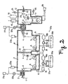
- Fig. 2 is a schematic view showing one embodiment of an apparatus for processing nonferrous metal alloy according to the present invention.
- Fig. 1 is a flowchart showing one embodiment of the method of processing nonferrous metal alloy.
- nonferrous metal alloy is assumed to be a plate, however, the method can be applied if the nonferrous metal alloy is formed like a wire or other shape.
- this embodiment teaches specific temperature conditions suitable for application to aluminum alloy; however, similar characteristics and effects can be expected if the present invention is applied to another kind of nonferrous metal alloy including copper, magnesium or the like.
- Step 1 a plate made of nonferrous metal alloy is rolled, at a given pressure, to a specific thickness by a rolling machine.
- This step is preferable to harden a plate, because it gives distortion in a plate that assists in generating a nucleus in the nonferrous metallic alloy when making a miniaturized structure therein.
- Step 1 may be repeated continuously in order to obtain a plate with a certain thickness, or may be employed as an intermediate step or a last step (followed by after-mentioned Step 7) in the whole process.
- pressure is given to nonferrous metal alloy in Step 1
- it is always effective to harden nonferrous metal alloy, even if a roller is not required.
- Step 2 dusts and impurities on the plate are removed.
- spraying liquid such as water or solvent on the plate, or soaking the plate in a tub filled with the above-stated liquid can be employed. It is also possible to spray air onto the plate in order to expect the similar effect.
- Step 3 the plate is soaked and passed through a first liquid metal sodium to heat the plate rapidly.
- the heating speed thereof may be more than 100 °C per second.
- the temperature of the first liquid metal sodium is preferably kept around 490 °C and is preferably controlled not to exceed 530 °C.
- liquid metal sodium for heating in Step 3.
- a heating furnace such as a gas furnace, and rapidly heating the plate sufficient to make most alloy elements added in the nonferrous metal alloy enter a solid solution state as a result, the same effect as using liquid metal sodium can be achieved.
- Step 4 the plate maintained at approximately 120 °C is soaked and passed through a second liquid metal sodium so that the plate is cooled rapidly soon after the heating step.
- crystal structures can be miniaturized while preserving the grating defects generated by Step 3 in the crystal structures of the nonferrous metal alloy.
- the solid solution state itself changes to a supersaturated solid solution state in which segregation and concentration are restrained, in accordance with solute atoms in the solid solution state.
- G-P zone Guide-Preston Zone
- the temperature of the second liquid metal sodium is set lower than 200 °C, such as about 150 °C, for example.
- Step 5 the plate made of nonferrous metal alloy is soaked and passed through water, or water is sprayed on the plate so that the plate is cooled further to room temperature. Simultaneously, the stuck liquid metal sodium (or solidified metal sodium) used in Steps 3 and 4 is washed and removed completely. For this step, growth of the G-P zone in the nonferrous metal alloy ceases to be in the supersaturated solid solution state. Therefore, Step 5 can also increase the hardness of the plate that became significantly hard in Step 4.
- Step 6 water applied in Step 5 is dried and removed completely from the surface of the plate.
- the plate is stored at a temperature approximately ranging from more than or equal to 100 °C to less than or equal to 200 °C, such as by keeping the plate in a constant temperature bath (heating tub).
- aging is executed, and the plate is further hardened by the effect of the aging deposition.
- Step 3 employing the step of rapid heating (Step 3) and the step of rapid cooling (Step 4) can efficiently form and keep grating defects in the crystal structures. As a result, growth of a G-P zone is restrained and the plate is significantly hardened.
- these steps employ liquid metal sodium, which can remain in a liquid phase for a wide temperature range between approximately 100 °C and 800 °C, to provide rapid heating and rapid cooling. Therefore, neither vaporization nor solidification can occur with contact to nonferrous metal alloy, and thereby stable heat transfer can be expected in the entire nonferrous metal alloy.
- Such a temperature characteristic of liquid metal sodium is especially effective when nonferrous metal alloy is cooled because, employing liquid metal sodium can realize the rapid cooling to restrain growth of a G-P zone in the nonferrous metal alloy.
- This embodiment which can realize the above-explained processing method, preferably uses the same conditions, such as for temperature.
- the plate 1 made of nonferrous metal alloy passes through a pressing machine (Step 1) and a surface cleaning machine (Step 2), which are not illustrated, and is transferred to a heating chamber 3 through a sealed entrance 2.
- the plate 1 is guided by carriers such as a guide roller 4 and a soaked guide roller 5, and is soaked in a liquid metal sodium tub (first liquid metal sodium tub) 6 where liquid metal sodium is stored (Step 3).
- the plate 1 is preferably heated rapidly to more than or equal to 450 °C.
- inert gas such as nitrogen, argon or the like is supplied continuously to avoid a reaction of the liquid metal sodium to air.
- the inert gas is provided from an inert gas supply source 27a by using a pump 22a, passes through inside of the sealed entrance 2 and the heating chamber 3, and covers the liquid metal sodium tub 6. Together with evaporated liquid metal sodium, the inert gas in the heating chamber 3 is trapped by a vapor trap 23a. After removal of the evaporated liquid metal sodium, inert gas is recirculated and supplied again by the pump 22a. To allow the flow of inert gas from the sealed entrance 2 to both outside and inside, air and moisture are prevented from entering the heating chamber 3, which also prevents leakage of evaporated liquid metal sodium in the heating chamber 3 to outside.
- the plate 1 pulled from the liquid metal sodium tub 6 passes through a liquid metal sodium remover 7, which sprays inert gas flow on the surface of the plate 1 to remove liquid metal sodium.
- the plate 1 then goes through a partition wall 31, which functions to provide thermal insulation, and is guided to a cooling chamber 8.
- the plate 1 is also transferred by the guide roller 4 and the soaked guide roller 5 in the cooling chamber 8, and is soaked in a liquid metal sodium tub (second liquid metal sodium tub) 9 where liquid metal sodium is stored (Step 4).
- the cooling chamber 8 is filled with inert gas being supplied continuously, similar to that in the heating chamber 3.
- Inert gas is supplied by an inert gas supply source 27a by using a pump 22b, passes through the inside of a sealed exit 11 and the cooling chamber 8, and covers the liquid metal sodium tub 9. Together with evaporated liquid metal sodium, the inert gas in the cooling chamber 8 is trapped by a vapor trap 23b. After removal of the evaporated liquid metal sodium, inert gas is recirculated and supplied again by the pump 22b.
- the plate 1 pulled from the liquid metal sodium tub 9 passes through a liquid metal sodium remover 10, which has the same function as the above-explained liquid metal sodium remover 7.
- the plate 1 is then guided to a water-cooling chamber 12 next to the cooling chamber 8 through the sealed exit 11.
- the plate 1 is soaked in a water tub 13 by using the guide roller 4 and a submerged guide roller 5a. Through heat exchange with the water in the water tub 13, the plate 1 is cooled to the vicinity of room temperature (Step 5).
- a water spray nozzle 14 connected to a washing water compressing pump 25 sprays water on both sides of the plate 1.
- inert gas is sprayed from a cleaning gas spray nozzle 29 onto the surface of the plate 1 for cleaning and drying (Step 6).
- a finishing process is made on the surface of the plate 1 by using a surface finish roller 30, and the plate 1 is transferred to outside of the water cooling chamber 12. Afterwards, the plate 1 is sent to a constant temperature bath (heating tub), not shown, for an aging process (Step 7).
- liquid metal sodium stuck on the plate 1 from the cooling chamber 8 may react to water in the water tub 13 to generate hydrogen.
- a hydrogen discharge pump 15 hydrogen remover
- a buffer tub 16 pressure fluctuation suppressor
- liquid metal sodium circulator systems 37a and 37b are connected to the heating chamber 3 and cooling chamber 8, respectively.
- liquid metal sodium in the liquid metal sodium tub 6 is guided to a decontamination tub 32a to remove impurities.
- a storage tank 36a can refill the liquid metal sodium if necessary. Heated by a heater 34 to a certain temperature, liquid metal sodium is returned to the liquid metal sodium tub 6 again.
- the series of circulation is carried out by a circulation pump 33a.
- liquid metal sodium in the liquid metal sodium tub 9 is guided to a decontamination tub 32b to remove impurities.
- a storage tank 36b can refill liquid metal sodium if necessary. Heated by a heater 35 to a certain temperature, liquid metal sodium is returned to the liquid metal sodium tub 9 again. The series of circulation is carried out by a circulation pump 33b.
- the guide roller 5, which is rotated while partially contacting the liquid metal sodium may be disabled from rotating if any liquid metal sodium is stuck to or deposited in the bearing. That is, the supporting mechanism of rotation of the guide roller 5 must be supported such that no liquid metal sodium is deposited. For this reason, as illustrated, the position of the supporting mechanism (rotating axis) of the guide roller 5 is preferably kept above the surface of the liquid metal sodium.
- Liquid metal sodium carried by the plate 1 may gradually deposit in the water tub 13 in the water-cooling chamber 12.
- a decontaminator 26 is connected to decontaminate.
- the above-explained process apparatus is equipped with many sensors, not shown.
- the detected signals from the sensors are calculated by a host computer, and the process apparatus is then program-controlled in accordance with the result of the host computer.
- the present invention it is possible to generate and keep grating defects in crystal structure by employing a rapid heating step and a rapid cooling step. As the result, growth of a G-P zone is suppressed and the plate can be hardened. Especially by using liquid metal sodium for heat exchange with the nonferrous metal alloy, stable heat transfer can be achieved and the strength of the nonferrous metal alloy can be assured.
- the nonferrous metal alloy can be used as structural material for aircrafts, trains and the like.
- the present invention does not limit nonferrous metal alloy to aluminum.
- Other kinds of nonferrous metal alloy such as copper, magnesium or the like can be applied to achieve the same characteristics and effects.
- the shape of nonferrous metal alloy is not limited to a plate, but is also applicable to wire or other shapes.
- the present invention is not limited to a continuous process system, in which the plate and wire are processed, but is also applicable to a batch process system for individual parts.
Landscapes
- Chemical & Material Sciences (AREA)
- Engineering & Computer Science (AREA)
- Materials Engineering (AREA)
- Thermal Sciences (AREA)
- Crystallography & Structural Chemistry (AREA)
- Mechanical Engineering (AREA)
- Physics & Mathematics (AREA)
- Metallurgy (AREA)
- Organic Chemistry (AREA)
- Manufacture And Refinement Of Metals (AREA)
- Chemical Treatment Of Metals (AREA)
- ing And Chemical Polishing (AREA)
- Cleaning And De-Greasing Of Metallic Materials By Chemical Methods (AREA)
Abstract
Description
- This invention relates to a method of processing nonferrous metal alloy and an apparatus for processing nonferrous metal alloy, and more particularly to a method for processing nonferrous metal alloy such as copper alloy, aluminum alloy, magnesium alloy and the like to improve strength thereof by employing a heating process.
- There are several ways known to improve the strength of nonferrous metal alloy, such as copper alloy, aluminum alloy, magnesium alloy and the like. Solid solution reinforcement, transition reinforcement, intergranular reinforcement, deposition reinforcement are typical examples of improving strength thereof.
- Solid solution reinforcement is a process of solidifying an element such as copper, magnesium, manganese, silicon or the like, in aluminum to achieve alloying.
- Transition reinforcement is a process of cold-forming alloy to generate transition of elements in the structure thereby increasing number of crystal grating defects (transition defects) therein.
- Intergranular reinforcement is a process of miniaturizing crystals and structures of alloy.
- Deposition reinforcement is a process of employing a phenomenon such that deposition of alloy proceeds over a time when a supersaturated solid solution state is kept at a low temperature, and that characteristics of the supersaturated solid solution change in accordance with temperature and time to be kept.
- In order to achieve ultrahigh strength by improving conventional aluminum alloy, however, there are still problems that have to be solved.
- For example, in case of employing a forming process to strengthen alloy, it is necessary to install many large and expensive rolling machines in series to be equipped with a huge and long forming line.
- Further, in case of employing a heating process to strengthen alloy, it is difficult to obtain a cooling speed quickly enough to miniaturize a crystal and structure of the alloy. Likewise, there exists a limit to the cooling speed in cooling a nonferrous meta; alloy in a supersaturated solid solution state, and this cannot restrain the growth of GP zone (Guinier-Preston Zone) so that improving hardening based on an aging deposition is insufficient. Here, "GP zone" means assembly of a flat or spherical deposit scaled approximately less than or equal to 10 nanometers, which contains solute atoms in deposited solid solution being gathered at the beginning of an aging hardening of an alloy.
- The present invention has been made in view of the above-mentioned circumstances and is intended to solve the above-mentioned problems. In particular, this invention provides a method of processing nonferrous metal alloy and an apparatus of processing nonferrous metal alloy capable of realizing ultrahigh strength of the nonferrous metal alloy.
- The present invention provides a method of processing nonferrous metal alloy, including a step of heating the nonferrous metal alloy with liquid metal sodium at a first temperature so that nonferrous metal alloy is put in a solid solution state, and cooling the nonferrous metal alloy with a liquid metal sodium at a second temperature to suppress growth of a Guinier-Preston (G-P) zone in nonferrous metal alloy while in the solid solution state.
- The present invention further provides an apparatus for processing nonferrous metal alloy, including: a first liquid metal sodium tub that stores liquid metal sodium at a first temperature and heats the nonferrous metal alloy such that the nonferrous metal alloy is put in a solid solution state, a second liquid metal sodium tub that stores liquid metal sodium at a second temperature and cools the nonferrous metal alloy to suppress growth of a Guinier-Preston (G-P) zone in the nonferrous metal alloy while in a solid solution state, and a carrier that carries the nonferrous metal alloy from the first liquid metal sodium tub to the second liquid metal sodium tub.
- Further objects, features and advantages of the present invention will become apparent from the detailed description of embodiments that allows, when considered together with the accompanying figures of drawings.
- The accompanying drawings, which are incorporated in and constitute a part of this specification, illustrate several preferred embodiments of the invention and, together with the description, serve to explain the principles of the invention.
- Fig. 1 is a flowchart showing one embodiment of a method of processing nonferrous metal alloy according to the present invention.
- Fig. 2 is a schematic view showing one embodiment of an apparatus for processing nonferrous metal alloy according to the present invention.
- Preferred embodiments of a method of processing nonferrous metal alloy and an apparatus of processing nonferrous metal alloy of the present invention will now be specifically described in more detail with reference to the accompanying drawings.
- Fig. 1 is a flowchart showing one embodiment of the method of processing nonferrous metal alloy. In this embodiment, nonferrous metal alloy is assumed to be a plate, however, the method can be applied if the nonferrous metal alloy is formed like a wire or other shape. Further, this embodiment teaches specific temperature conditions suitable for application to aluminum alloy; however, similar characteristics and effects can be expected if the present invention is applied to another kind of nonferrous metal alloy including copper, magnesium or the like.
- In
Step 1, a plate made of nonferrous metal alloy is rolled, at a given pressure, to a specific thickness by a rolling machine. This step is preferable to harden a plate, because it gives distortion in a plate that assists in generating a nucleus in the nonferrous metallic alloy when making a miniaturized structure therein. Note thatStep 1 may be repeated continuously in order to obtain a plate with a certain thickness, or may be employed as an intermediate step or a last step (followed by after-mentioned Step 7) in the whole process. As long as pressure is given to nonferrous metal alloy inStep 1, it is always effective to harden nonferrous metal alloy, even if a roller is not required. - In
Step 2, dusts and impurities on the plate are removed. For example, spraying liquid such as water or solvent on the plate, or soaking the plate in a tub filled with the above-stated liquid can be employed. It is also possible to spray air onto the plate in order to expect the similar effect. - In
Step 3, the plate is soaked and passed through a first liquid metal sodium to heat the plate rapidly. Preferably, the heating speed thereof may be more than 100 °C per second. By employing this step, alloy elements added in the nonferrous metal alloy enters a solid solution state. As a result, a lot of grating defects are formed in an almost all crystal structure of the nonferrous metal alloy due to transition in the crystal structure. In addition, growth of crystal particles is suppressed. - Note that the temperature of the first liquid metal sodium is preferably kept around 490 °C and is preferably controlled not to exceed 530 °C.
- Further, it is not required to employ liquid metal sodium for heating in
Step 3. By employing a heating furnace such as a gas furnace, and rapidly heating the plate sufficient to make most alloy elements added in the nonferrous metal alloy enter a solid solution state as a result, the same effect as using liquid metal sodium can be achieved. - In
Step 4, the plate maintained at approximately 120 °C is soaked and passed through a second liquid metal sodium so that the plate is cooled rapidly soon after the heating step. For this step, crystal structures can be miniaturized while preserving the grating defects generated byStep 3 in the crystal structures of the nonferrous metal alloy. Also, the solid solution state itself changes to a supersaturated solid solution state in which segregation and concentration are restrained, in accordance with solute atoms in the solid solution state. As the result of these effects, growth of a G-P zone (Guinier-Preston Zone), in which solute atoms in the solid solution state are gathered and deposited, is suppressed. - In order to suppress growth of the G-P zone, it is effective to keep the temperature of the second liquid metal sodium as low as possible. This can provide significantly hard nonferrous metal alloy. The effect can be achieved if the temperature of the second liquid metal sodium is set lower than 200 °C, such as about 150 °C, for example.
- In
Step 5, the plate made of nonferrous metal alloy is soaked and passed through water, or water is sprayed on the plate so that the plate is cooled further to room temperature. Simultaneously, the stuck liquid metal sodium (or solidified metal sodium) used inSteps Step 5 can also increase the hardness of the plate that became significantly hard inStep 4. - In
Step 6, water applied inStep 5 is dried and removed completely from the surface of the plate. - In the
last Step 7, the plate is stored at a temperature approximately ranging from more than or equal to 100 °C to less than or equal to 200 °C, such as by keeping the plate in a constant temperature bath (heating tub). For this step, aging is executed, and the plate is further hardened by the effect of the aging deposition. - According to the series of steps thus explained, it is possible to provide a nonferrous metal alloy having ultrahigh strength.
- Among these steps in the embodiment, employing the step of rapid heating (Step 3) and the step of rapid cooling (Step 4) can efficiently form and keep grating defects in the crystal structures. As a result, growth of a G-P zone is restrained and the plate is significantly hardened.
- Further, these steps employ liquid metal sodium, which can remain in a liquid phase for a wide temperature range between approximately 100 °C and 800 °C, to provide rapid heating and rapid cooling. Therefore, neither vaporization nor solidification can occur with contact to nonferrous metal alloy, and thereby stable heat transfer can be expected in the entire nonferrous metal alloy.
- Such a temperature characteristic of liquid metal sodium is especially effective when nonferrous metal alloy is cooled because, employing liquid metal sodium can realize the rapid cooling to restrain growth of a G-P zone in the nonferrous metal alloy.
- Consequently, a temperature gradient of the nonferrous metal alloy according to heat exchange can be controlled, and the strength of the processed nonferrous metal alloy can be fully assured.
- Next, an apparatus for processing nonferrous metal alloy according to one embodiment of the present invention is explained. This embodiment, which can realize the above-explained processing method, preferably uses the same conditions, such as for temperature.
- First, the
plate 1 made of nonferrous metal alloy passes through a pressing machine (Step 1) and a surface cleaning machine (Step 2), which are not illustrated, and is transferred to aheating chamber 3 through a sealedentrance 2. In theheating chamber 3, theplate 1 is guided by carriers such as aguide roller 4 and asoaked guide roller 5, and is soaked in a liquid metal sodium tub (first liquid metal sodium tub) 6 where liquid metal sodium is stored (Step 3). Theplate 1 is preferably heated rapidly to more than or equal to 450 °C. - In the
heating chamber 3, inert gas such as nitrogen, argon or the like is supplied continuously to avoid a reaction of the liquid metal sodium to air. The inert gas is provided from an inertgas supply source 27a by using apump 22a, passes through inside of the sealedentrance 2 and theheating chamber 3, and covers the liquidmetal sodium tub 6. Together with evaporated liquid metal sodium, the inert gas in theheating chamber 3 is trapped by avapor trap 23a. After removal of the evaporated liquid metal sodium, inert gas is recirculated and supplied again by thepump 22a. To allow the flow of inert gas from the sealedentrance 2 to both outside and inside, air and moisture are prevented from entering theheating chamber 3, which also prevents leakage of evaporated liquid metal sodium in theheating chamber 3 to outside. - The
plate 1 pulled from the liquidmetal sodium tub 6 passes through a liquidmetal sodium remover 7, which sprays inert gas flow on the surface of theplate 1 to remove liquid metal sodium. Theplate 1 then goes through apartition wall 31, which functions to provide thermal insulation, and is guided to a cooling chamber 8. - Similarly to the
heating chamber 3, theplate 1 is also transferred by theguide roller 4 and thesoaked guide roller 5 in the cooling chamber 8, and is soaked in a liquid metal sodium tub (second liquid metal sodium tub) 9 where liquid metal sodium is stored (Step 4). Theplate 1, which had been heated to a high temperature, is cooled rapidly to around 120 °C. - Here, the cooling chamber 8 is filled with inert gas being supplied continuously, similar to that in the
heating chamber 3. Inert gas is supplied by an inertgas supply source 27a by using apump 22b, passes through the inside of a sealed exit 11 and the cooling chamber 8, and covers the liquid metal sodium tub 9. Together with evaporated liquid metal sodium, the inert gas in the cooling chamber 8 is trapped by avapor trap 23b. After removal of the evaporated liquid metal sodium, inert gas is recirculated and supplied again by thepump 22b. - The
plate 1 pulled from the liquid metal sodium tub 9 passes through a liquidmetal sodium remover 10, which has the same function as the above-explained liquidmetal sodium remover 7. Theplate 1 is then guided to a water-coolingchamber 12 next to the cooling chamber 8 through the sealed exit 11. - In the water-cooling
chamber 12, theplate 1 is soaked in awater tub 13 by using theguide roller 4 and a submerged guide roller 5a. Through heat exchange with the water in thewater tub 13, theplate 1 is cooled to the vicinity of room temperature (Step 5). Here, to remove all liquid metal sodium on theplate 1, a water spray nozzle 14 connected to a washing water compressing pump 25 sprays water on both sides of theplate 1. By driving a cleaninggas compressing pump 24, inert gas is sprayed from a cleaninggas spray nozzle 29 onto the surface of theplate 1 for cleaning and drying (Step 6). - Finally, a finishing process is made on the surface of the
plate 1 by using asurface finish roller 30, and theplate 1 is transferred to outside of thewater cooling chamber 12. Afterwards, theplate 1 is sent to a constant temperature bath (heating tub), not shown, for an aging process (Step 7). - In the water-cooling
chamber 12, liquid metal sodium stuck on theplate 1 from the cooling chamber 8 may react to water in thewater tub 13 to generate hydrogen. To discharge such hydrogen safely, a hydrogen discharge pump 15 (hydrogen remover) is connected. Further, to suppress pressure fluctuation in the water-coolingchamber 12, a buffer tub 16 (pressure fluctuation suppressor) is connected. - In the present invention, it is preferable to control physical properties of the liquid metal sodium so as to provide nonferrous metal alloy having consistently stable strength. In the liquid
metal sodium tub 6 and the liquid metal sodium tub 9, however, theplate 1 and liquid metal sodium repeatedly exchange heat and the temperature of the liquid metal sodium gradually changes. Simultaneously, the purity of the liquid metal sodium is decreased due to oil, rust, dust and the like carried by theplate 1. In order to avoid this, liquid metalsodium circulator systems heating chamber 3 and cooling chamber 8, respectively. - Specifically, liquid metal sodium in the liquid
metal sodium tub 6 is guided to adecontamination tub 32a to remove impurities. Astorage tank 36a can refill the liquid metal sodium if necessary. Heated by aheater 34 to a certain temperature, liquid metal sodium is returned to the liquidmetal sodium tub 6 again. The series of circulation is carried out by acirculation pump 33a. Similarly, liquid metal sodium in the liquid metal sodium tub 9 is guided to adecontamination tub 32b to remove impurities. Astorage tank 36b can refill liquid metal sodium if necessary. Heated by aheater 35 to a certain temperature, liquid metal sodium is returned to the liquid metal sodium tub 9 again. The series of circulation is carried out by acirculation pump 33b. - Meanwhile, the
guide roller 5, which is rotated while partially contacting the liquid metal sodium, may be disabled from rotating if any liquid metal sodium is stuck to or deposited in the bearing. That is, the supporting mechanism of rotation of theguide roller 5 must be supported such that no liquid metal sodium is deposited. For this reason, as illustrated, the position of the supporting mechanism (rotating axis) of theguide roller 5 is preferably kept above the surface of the liquid metal sodium. - Liquid metal sodium carried by the
plate 1 may gradually deposit in thewater tub 13 in the water-coolingchamber 12. To decontaminate, adecontaminator 26 is connected. - The above-explained process apparatus is equipped with many sensors, not shown. The detected signals from the sensors are calculated by a host computer, and the process apparatus is then program-controlled in accordance with the result of the host computer.
- According to the present invention, it is possible to generate and keep grating defects in crystal structure by employing a rapid heating step and a rapid cooling step. As the result, growth of a G-P zone is suppressed and the plate can be hardened. Especially by using liquid metal sodium for heat exchange with the nonferrous metal alloy, stable heat transfer can be achieved and the strength of the nonferrous metal alloy can be assured. The nonferrous metal alloy can be used as structural material for aircrafts, trains and the like.
- The foregoing discussion discloses and describes merely a number of exemplary embodiments of the present invention. As will be understood by those skilled in the art, the present invention may be embodied in other specific forms without departing from the spirit or essential characteristics thereof.
- Accordingly, the disclosure of the present invention is intended to be illustrative, but not limiting, of the scope of the invention, which is set forth in the following claims.
- Thus, the present invention may be embodied in various ways within the scope of the spirit of the invention.
- The present invention does not limit nonferrous metal alloy to aluminum. Other kinds of nonferrous metal alloy such as copper, magnesium or the like can be applied to achieve the same characteristics and effects. The shape of nonferrous metal alloy is not limited to a plate, but is also applicable to wire or other shapes. Of course, the present invention is not limited to a continuous process system, in which the plate and wire are processed, but is also applicable to a batch process system for individual parts.
- The entire contents of Japanese Patent Application 2002-307477, filed October 22, 2002, are incorporated herein by reference.
- It is explicitly stated that all features disclosed in the description and/or the claims are intended to be disclosed separately and independently from each other for the purpose of original disclosure as well as for the purpose of restricting the claimed invention independent of the compositions of the features in the embodiments and/or the claims. It is explicitly stated that all value ranges or indications of groups of entities disclose every possible intermediate value or intermediate entity for the purpose of original disclosure as well as for the purpose of restricting the claimed invention.
Claims (34)
- A method of processing nonferrous metal alloy, comprising the steps of:heating the nonferrous metal alloy such that the nonferrous metal alloy is put in a solid solution state, andcooling the nonferrous metal alloy to suppress growth of a Guinier-Preston (G-P) zone in the nonferrous metal alloy while in the solid solution state.
- The method according to claim 1, where the nonferrous metal alloy is heated by a liquid metal sodium.
- The method according to claim 1 or 2, where the nonferrous metal alloy is cooled by a liquid metal sodium.
- A method of processing nonferrous metal alloy, comprising:heating the nonferrous metal alloy with a liquid metal sodium at a first temperature to put the nonferrous metal alloy in a solid solution state; andcooling the nonferrous metal alloy with a liquid metal sodium at a second temperature to suppress growth of a Guinier-Preston (G-P) zone in the nonferrous metal alloy while in the solid solution state.
- The method according to one of claims 1 to 4, wherein the nonferrous metal alloy includes aluminum.
- The method according to one of claims 1 to 5, wherein the first temperature is set to generate a grating defect caused by transition in a crystal structure of the nonferrous metal alloy.
- The method according to one of claims 1 to 6, wherein the first temperature is set such that an alloy element in the nonferrous metal alloy enters the solid solution state.
- The method according to one of claims 1 to 7, wherein the first temperature is set to be more than or equal to 450°C.
- The method according to one of claims 1 to 8, wherein the second temperature is set such that the crystal structure of the nonferrous metal alloy is miniaturized while maintaining a grating defect caused by transition in a crystal structure therein, and that the solid solution state is supersaturated.
- The method according to one of claims 1 to 9, further comprising cooling the nonferrous metal alloy by water.
- The method according to claim 10, wherein the cooling by water includes removing liquid metal sodium left on the nonferrous metal alloy.
- The method according to claims 10 or 11, wherein the cooling by water acts such that the solid solution state of the nonferrous metal alloy stops growth of the G-P zone and a supersaturated solid solution state is entered.
- The method according to one of claims 10 to 12, further comprising heating the nonferrous metal alloy by an aging process after the cooling by water.
- The method according to claim 13, wherein the heating by the aging process includes keeping the nonferrous metal alloy at a temperature approximately between 100° C and 200° C in a certain period.
- The method according to claims 13 or 14, further comprising rolling the nonferrous metal alloy after heating by the aging process.
- An apparatus for processing nonferrous metal alloy, comprising:a heating furnace that heats the nonferrous metal alloy such that nonferrous metal alloy is put in a solid solution state,a liquid metal sodium tub that stores liquid metal sodium and cools the nonferrous metal alloy to suppress growth of a Guinier-Preston (G-P) zone in the nonferrous metal alloy while in the solid solution state, anda carrier that carries the nonferrous metal alloy from the heating furnace to the liquid metal sodium tub.
- The apparatus of claim 16, wherein the heating furnace is at a first temperature, and the liquid metal sodium tub is at a second temperature.
- An apparatus for processing nonferrous metal alloy, comprising:a first liquid metal sodium tub that stores liquid metal sodium at a first temperature and heats the nonferrous metal alloy to put the nonferrous metal alloy in a solid solution state;a second liquid metal sodium tub that stores liquid metal sodium at a second temperature and cools the nonferrous metal alloy to suppress growth of a Guinier-Preston (G-P) zone in the nonferrous metal alloy while in the solid solution state; anda carrier that carries the nonferrous metal alloy from the first liquid metal sodium tub to the second liquid metal sodium tub.
- The apparatus according to one of claims 16 to 18, wherein the nonferrous metal alloy includes aluminum.
- The apparatus according to one of claims 17 to 19, wherein the first temperature is set to generate a grating defect caused by transition in a crystal structure in the nonferrous metal alloy.
- The apparatus according to one of claims 17 to 20, wherein the first temperature is set such that alloy element in the nonferrous metal alloy enters a solid solution state. ,
- The apparatus according to one of claims 17 to 21, wherein the first temperature is set to be more than or equal to 450° C.
- The apparatus according one of claims 17 to 22, wherein the second temperature is set such that the crystal structure of the nonferrous metal alloy is miniaturized while maintaining a grating defect caused by transition in a crystal structure therein, and that the solid solution state is supersaturated.
- The apparatus according to one of claims 16 to 23, further comprising a water tub that cools the nonferrous metal alloy processed by the second liquid metal sodium tub.
- The apparatus according to claim 24, wherein the water tub is used to remove liquid metal sodium left on the nonferrous metal alloy.
- The apparatus according to claim 24 or 25, wherein the water tub is used such that the solid solution state of the nonferrous metal alloy stops growth of the G-P zone and a supersaturated solid solution is entered.
- The apparatus according to one of claims 16 to 26, further comprising a heating tub that heats the nonferrous metal alloy by an aging process.
- The apparatus according to claim 27, wherein the heating tub is used to keep the nonferrous metal alloy at a temperature approximately between 100° C and 200° C in a certain period.
- The apparatus according to claims 27 or 28, further comprising a pressing machine that rolls the nonferrous metal alloy processed by the heating tub.
- The apparatus according to one of claims 16 to 29, further comprising a liquid metal sodium circulating system that controls the temperature of the liquid metal sodium in each of the first liquid metal sodium tub and the second liquid metal sodium tub.
- The apparatus according to one of claims 16 to 30, further comprising an inert gas supply source that covers the first liquid metal sodium tub and the second liquid metal sodium tub with inert gas.
- The apparatus according to one of claims 24 to 31, further comprising:a water cooling chamber having a further water tub,a hydrogen remover that removes hydrogen in the water cooling chamber, anda pressure fluctuation absorber that absorb the fluctuation of pressure in the water cooling chamber.
- The apparatus according to one of claims 16 to 32, wherein the carrier includes a roller partially soaked in liquid metal sodium, the roller having a supporting mechanism that supports the rotating axis thereof such that the rotating axis is disposed above the liquid metal sodium.
- A nonferrous metal alloy formed according to the method of one of claims 1 to 15.
Applications Claiming Priority (2)
| Application Number | Priority Date | Filing Date | Title |
|---|---|---|---|
| JP2002307477A JP2004143486A (en) | 2002-10-22 | 2002-10-22 | Nonferrous metal alloy processing method and nonferrous metal alloy processing apparatus |
| JP2002307477 | 2002-10-22 |
Publications (2)
| Publication Number | Publication Date |
|---|---|
| EP1413641A1 true EP1413641A1 (en) | 2004-04-28 |
| EP1413641B1 EP1413641B1 (en) | 2006-08-16 |
Family
ID=32064320
Family Applications (1)
| Application Number | Title | Priority Date | Filing Date |
|---|---|---|---|
| EP03023905A Expired - Lifetime EP1413641B1 (en) | 2002-10-22 | 2003-10-21 | Method for processing aluminium alloy |
Country Status (5)
| Country | Link |
|---|---|
| US (1) | US20040134575A1 (en) |
| EP (1) | EP1413641B1 (en) |
| JP (1) | JP2004143486A (en) |
| CA (1) | CA2445910A1 (en) |
| DE (1) | DE60307570T2 (en) |
Cited By (1)
| Publication number | Priority date | Publication date | Assignee | Title |
|---|---|---|---|---|
| CN105441836A (en) * | 2015-11-30 | 2016-03-30 | 中航飞机股份有限公司西安飞机分公司 | Aluminum alloy thin sheet quenching deformation control method |
Families Citing this family (3)
| Publication number | Priority date | Publication date | Assignee | Title |
|---|---|---|---|---|
| US20060225821A1 (en) * | 2004-06-03 | 2006-10-12 | Japan Thermotec Co., Ltd. | Method and apparatus for heat-treating solid alloy material |
| JP5641016B2 (en) | 2012-06-08 | 2014-12-17 | トヨタ自動車株式会社 | Heat treatment method and heat treatment furnace |
| CN115141924A (en) * | 2022-06-28 | 2022-10-04 | 烟台万隆真空冶金股份有限公司 | Rapid heating device and heating method for copper alloy cast wheel |
Citations (4)
| Publication number | Priority date | Publication date | Assignee | Title |
|---|---|---|---|---|
| US2797177A (en) * | 1953-01-14 | 1957-06-25 | John D Keller | Method of and apparatus for annealing strip steel |
| US3256119A (en) * | 1965-04-20 | 1966-06-14 | George W Jernstedt | Method of annealing steel strip |
| EP1057897A2 (en) * | 1999-06-03 | 2000-12-06 | Kabushiki Kaisha Toshiba | Apparatus and process for heat treating metallic material |
| JP2001262259A (en) * | 2000-03-17 | 2001-09-26 | Toshiba Corp | High corrosion resistant zirconium alloy, structural material for nuclear reactor core and method of manufacturing the same |
Family Cites Families (3)
| Publication number | Priority date | Publication date | Assignee | Title |
|---|---|---|---|---|
| US3947297A (en) * | 1973-04-18 | 1976-03-30 | The United States Of America As Represented By The Secretary Of The Air Force | Treatment of aluminum alloys |
| US4030947A (en) * | 1975-09-10 | 1977-06-21 | Kemper Eugene L | Heating treatment method and system of utilizing same |
| US6492631B2 (en) * | 2000-04-27 | 2002-12-10 | Kabushiki Kaisha Toshiba | Apparatus for quenching metallic material |
-
2002
- 2002-10-22 JP JP2002307477A patent/JP2004143486A/en active Pending
-
2003
- 2003-10-21 CA CA002445910A patent/CA2445910A1/en not_active Abandoned
- 2003-10-21 DE DE60307570T patent/DE60307570T2/en not_active Expired - Fee Related
- 2003-10-21 EP EP03023905A patent/EP1413641B1/en not_active Expired - Lifetime
- 2003-10-22 US US10/689,835 patent/US20040134575A1/en not_active Abandoned
Patent Citations (4)
| Publication number | Priority date | Publication date | Assignee | Title |
|---|---|---|---|---|
| US2797177A (en) * | 1953-01-14 | 1957-06-25 | John D Keller | Method of and apparatus for annealing strip steel |
| US3256119A (en) * | 1965-04-20 | 1966-06-14 | George W Jernstedt | Method of annealing steel strip |
| EP1057897A2 (en) * | 1999-06-03 | 2000-12-06 | Kabushiki Kaisha Toshiba | Apparatus and process for heat treating metallic material |
| JP2001262259A (en) * | 2000-03-17 | 2001-09-26 | Toshiba Corp | High corrosion resistant zirconium alloy, structural material for nuclear reactor core and method of manufacturing the same |
Non-Patent Citations (1)
| Title |
|---|
| PATENT ABSTRACTS OF JAPAN vol. 2000, no. 26 1 July 2002 (2002-07-01) * |
Cited By (2)
| Publication number | Priority date | Publication date | Assignee | Title |
|---|---|---|---|---|
| CN105441836A (en) * | 2015-11-30 | 2016-03-30 | 中航飞机股份有限公司西安飞机分公司 | Aluminum alloy thin sheet quenching deformation control method |
| CN105441836B (en) * | 2015-11-30 | 2017-03-22 | 中航飞机股份有限公司西安飞机分公司 | Aluminum alloy thin sheet quenching deformation control method |
Also Published As
| Publication number | Publication date |
|---|---|
| US20040134575A1 (en) | 2004-07-15 |
| JP2004143486A (en) | 2004-05-20 |
| CA2445910A1 (en) | 2004-04-22 |
| EP1413641B1 (en) | 2006-08-16 |
| DE60307570T2 (en) | 2007-08-09 |
| DE60307570D1 (en) | 2006-09-28 |
Similar Documents
| Publication | Publication Date | Title |
|---|---|---|
| KR20010093105A (en) | Method for galvanizing and galvannealing employing a bath of zinc and aluminum | |
| KR20010041309A (en) | Installation for making cold-rolled stainless steel bands | |
| JP2004513237A (en) | Metal strip dip coating equipment | |
| EP1413641B1 (en) | Method for processing aluminium alloy | |
| US5142873A (en) | Vapor control system for vapor degreasing/defluxing equipment | |
| US5048548A (en) | Vapor control system for vapor degreasing/defluxing equipment | |
| US4066477A (en) | Method of maintaining temperature of salt bath during quenching of steel wire | |
| JP2001335854A (en) | Apparatus and method for refining high purity metal | |
| CA3147396C (en) | Compact aluminium alloy heat treatment method | |
| EP1149923B1 (en) | Apparatus for quenching metallic material | |
| JP2003506573A (en) | Hot-dip galvanizing method and apparatus for strip steel | |
| EP1057897B1 (en) | Apparatus and process for heat treating metallic material | |
| Tiryakioglu et al. | Quenching aluminum components in water: Problems and alternatives | |
| US6811827B2 (en) | Method and installation for hot dip coating metal strips | |
| JPS6354046B2 (en) | ||
| US3145119A (en) | Float casting | |
| GB1101973A (en) | Method of coating ferrous metal with molten aluminium or aluminium alloy | |
| US1080059A (en) | Process for producing clean or deoxidized metal surfaces. | |
| KR100905906B1 (en) | Hot Rolled Steel Sheet Manufacturing Machine | |
| JP2002086254A (en) | Metal material processing method and apparatus | |
| JP2986670B2 (en) | Apparatus and method for producing Cr-containing corrosion-resistant steel strip | |
| KR101220664B1 (en) | Apparatus for recoverying metal zinc powder and method for recovering metal zinc powder from galvanized steel sheet | |
| JP2002332524A (en) | Metal material processing method and apparatus | |
| KR20020029094A (en) | Method and installation for hot dip galvanizing hot rolled steel strip | |
| JP2001520319A (en) | Complex hardening of metal products |
Legal Events
| Date | Code | Title | Description |
|---|---|---|---|
| PUAI | Public reference made under article 153(3) epc to a published international application that has entered the european phase |
Free format text: ORIGINAL CODE: 0009012 |
|
| 17P | Request for examination filed |
Effective date: 20031021 |
|
| AK | Designated contracting states |
Kind code of ref document: A1 Designated state(s): AT BE BG CH CY CZ DE DK EE ES FI FR GB GR HU IE IT LI LU MC NL PT RO SE SI SK TR |
|
| AX | Request for extension of the european patent |
Extension state: AL LT LV MK |
|
| 17Q | First examination report despatched |
Effective date: 20040622 |
|
| AKX | Designation fees paid |
Designated state(s): DE FR GB IT SE |
|
| GRAP | Despatch of communication of intention to grant a patent |
Free format text: ORIGINAL CODE: EPIDOSNIGR1 |
|
| RTI1 | Title (correction) |
Free format text: METHOD FOR PROCESSING ALUMINIUM ALLOY |
|
| GRAS | Grant fee paid |
Free format text: ORIGINAL CODE: EPIDOSNIGR3 |
|
| GRAA | (expected) grant |
Free format text: ORIGINAL CODE: 0009210 |
|
| RIN1 | Information on inventor provided before grant (corrected) |
Inventor name: NINOMIYA, SUSUMU |
|
| AK | Designated contracting states |
Kind code of ref document: B1 Designated state(s): DE FR GB IT SE |
|
| PG25 | Lapsed in a contracting state [announced via postgrant information from national office to epo] |
Ref country code: IT Free format text: LAPSE BECAUSE OF FAILURE TO SUBMIT A TRANSLATION OF THE DESCRIPTION OR TO PAY THE FEE WITHIN THE PRESCRIBED TIME-LIMIT;WARNING: LAPSES OF ITALIAN PATENTS WITH EFFECTIVE DATE BEFORE 2007 MAY HAVE OCCURRED AT ANY TIME BEFORE 2007. THE CORRECT EFFECTIVE DATE MAY BE DIFFERENT FROM THE ONE RECORDED. Effective date: 20060816 |
|
| REG | Reference to a national code |
Ref country code: GB Ref legal event code: FG4D |
|
| REF | Corresponds to: |
Ref document number: 60307570 Country of ref document: DE Date of ref document: 20060928 Kind code of ref document: P |
|
| PGFP | Annual fee paid to national office [announced via postgrant information from national office to epo] |
Ref country code: SE Payment date: 20061004 Year of fee payment: 4 |
|
| PGFP | Annual fee paid to national office [announced via postgrant information from national office to epo] |
Ref country code: DE Payment date: 20061019 Year of fee payment: 4 |
|
| PGFP | Annual fee paid to national office [announced via postgrant information from national office to epo] |
Ref country code: IT Payment date: 20061031 Year of fee payment: 4 |
|
| REG | Reference to a national code |
Ref country code: SE Ref legal event code: TRGR |
|
| ET | Fr: translation filed | ||
| REG | Reference to a national code |
Ref country code: GB Ref legal event code: 746 Effective date: 20070318 |
|
| PLBE | No opposition filed within time limit |
Free format text: ORIGINAL CODE: 0009261 |
|
| STAA | Information on the status of an ep patent application or granted ep patent |
Free format text: STATUS: NO OPPOSITION FILED WITHIN TIME LIMIT |
|
| 26N | No opposition filed |
Effective date: 20070518 |
|
| EUG | Se: european patent has lapsed | ||
| GBPC | Gb: european patent ceased through non-payment of renewal fee |
Effective date: 20071021 |
|
| PG25 | Lapsed in a contracting state [announced via postgrant information from national office to epo] |
Ref country code: DE Free format text: LAPSE BECAUSE OF NON-PAYMENT OF DUE FEES Effective date: 20080501 |
|
| REG | Reference to a national code |
Ref country code: FR Ref legal event code: ST Effective date: 20080630 |
|
| PG25 | Lapsed in a contracting state [announced via postgrant information from national office to epo] |
Ref country code: SE Free format text: LAPSE BECAUSE OF NON-PAYMENT OF DUE FEES Effective date: 20071022 |
|
| PGFP | Annual fee paid to national office [announced via postgrant information from national office to epo] |
Ref country code: FR Payment date: 20061010 Year of fee payment: 4 |
|
| PG25 | Lapsed in a contracting state [announced via postgrant information from national office to epo] |
Ref country code: GB Free format text: LAPSE BECAUSE OF NON-PAYMENT OF DUE FEES Effective date: 20071021 |
|
| PG25 | Lapsed in a contracting state [announced via postgrant information from national office to epo] |
Ref country code: FR Free format text: LAPSE BECAUSE OF NON-PAYMENT OF DUE FEES Effective date: 20071031 |
|
| PG25 | Lapsed in a contracting state [announced via postgrant information from national office to epo] |
Ref country code: IT Free format text: LAPSE BECAUSE OF NON-PAYMENT OF DUE FEES Effective date: 20071021 |