EP1413520A1 - Sealing jaw - Google Patents
Sealing jaw Download PDFInfo
- Publication number
- EP1413520A1 EP1413520A1 EP20020023851 EP02023851A EP1413520A1 EP 1413520 A1 EP1413520 A1 EP 1413520A1 EP 20020023851 EP20020023851 EP 20020023851 EP 02023851 A EP02023851 A EP 02023851A EP 1413520 A1 EP1413520 A1 EP 1413520A1
- Authority
- EP
- European Patent Office
- Prior art keywords
- sealing
- sealing jaw
- pressure element
- jaw according
- heating device
- Prior art date
- Legal status (The legal status is an assumption and is not a legal conclusion. Google has not performed a legal analysis and makes no representation as to the accuracy of the status listed.)
- Granted
Links
Images




Classifications
-
- B—PERFORMING OPERATIONS; TRANSPORTING
- B65—CONVEYING; PACKING; STORING; HANDLING THIN OR FILAMENTARY MATERIAL
- B65B—MACHINES, APPARATUS OR DEVICES FOR, OR METHODS OF, PACKAGING ARTICLES OR MATERIALS; UNPACKING
- B65B51/00—Devices for, or methods of, sealing or securing package folds or closures; Devices for gathering or twisting wrappers, or necks of bags
- B65B51/10—Applying or generating heat or pressure or combinations thereof
- B65B51/22—Applying or generating heat or pressure or combinations thereof by friction or ultrasonic or high-frequency electrical means
-
- B—PERFORMING OPERATIONS; TRANSPORTING
- B65—CONVEYING; PACKING; STORING; HANDLING THIN OR FILAMENTARY MATERIAL
- B65B—MACHINES, APPARATUS OR DEVICES FOR, OR METHODS OF, PACKAGING ARTICLES OR MATERIALS; UNPACKING
- B65B51/00—Devices for, or methods of, sealing or securing package folds or closures; Devices for gathering or twisting wrappers, or necks of bags
- B65B51/10—Applying or generating heat or pressure or combinations thereof
- B65B51/22—Applying or generating heat or pressure or combinations thereof by friction or ultrasonic or high-frequency electrical means
- B65B51/227—Applying or generating heat or pressure or combinations thereof by friction or ultrasonic or high-frequency electrical means by induction welding
-
- B—PERFORMING OPERATIONS; TRANSPORTING
- B29—WORKING OF PLASTICS; WORKING OF SUBSTANCES IN A PLASTIC STATE IN GENERAL
- B29C—SHAPING OR JOINING OF PLASTICS; SHAPING OF MATERIAL IN A PLASTIC STATE, NOT OTHERWISE PROVIDED FOR; AFTER-TREATMENT OF THE SHAPED PRODUCTS, e.g. REPAIRING
- B29C65/00—Joining or sealing of preformed parts, e.g. welding of plastics materials; Apparatus therefor
- B29C65/02—Joining or sealing of preformed parts, e.g. welding of plastics materials; Apparatus therefor by heating, with or without pressure
- B29C65/34—Joining or sealing of preformed parts, e.g. welding of plastics materials; Apparatus therefor by heating, with or without pressure using heated elements which remain in the joint, e.g. "verlorenes Schweisselement"
- B29C65/36—Joining or sealing of preformed parts, e.g. welding of plastics materials; Apparatus therefor by heating, with or without pressure using heated elements which remain in the joint, e.g. "verlorenes Schweisselement" heated by induction
- B29C65/3604—Joining or sealing of preformed parts, e.g. welding of plastics materials; Apparatus therefor by heating, with or without pressure using heated elements which remain in the joint, e.g. "verlorenes Schweisselement" heated by induction characterised by the type of elements heated by induction which remain in the joint
- B29C65/3656—Joining or sealing of preformed parts, e.g. welding of plastics materials; Apparatus therefor by heating, with or without pressure using heated elements which remain in the joint, e.g. "verlorenes Schweisselement" heated by induction characterised by the type of elements heated by induction which remain in the joint being a layer of a multilayer part to be joined, e.g. for joining plastic-metal laminates
-
- B—PERFORMING OPERATIONS; TRANSPORTING
- B29—WORKING OF PLASTICS; WORKING OF SUBSTANCES IN A PLASTIC STATE IN GENERAL
- B29C—SHAPING OR JOINING OF PLASTICS; SHAPING OF MATERIAL IN A PLASTIC STATE, NOT OTHERWISE PROVIDED FOR; AFTER-TREATMENT OF THE SHAPED PRODUCTS, e.g. REPAIRING
- B29C65/00—Joining or sealing of preformed parts, e.g. welding of plastics materials; Apparatus therefor
- B29C65/02—Joining or sealing of preformed parts, e.g. welding of plastics materials; Apparatus therefor by heating, with or without pressure
- B29C65/34—Joining or sealing of preformed parts, e.g. welding of plastics materials; Apparatus therefor by heating, with or without pressure using heated elements which remain in the joint, e.g. "verlorenes Schweisselement"
- B29C65/36—Joining or sealing of preformed parts, e.g. welding of plastics materials; Apparatus therefor by heating, with or without pressure using heated elements which remain in the joint, e.g. "verlorenes Schweisselement" heated by induction
- B29C65/3668—Joining or sealing of preformed parts, e.g. welding of plastics materials; Apparatus therefor by heating, with or without pressure using heated elements which remain in the joint, e.g. "verlorenes Schweisselement" heated by induction characterised by the means for supplying heat to said heated elements which remain in the join, e.g. special induction coils
-
- B—PERFORMING OPERATIONS; TRANSPORTING
- B29—WORKING OF PLASTICS; WORKING OF SUBSTANCES IN A PLASTIC STATE IN GENERAL
- B29C—SHAPING OR JOINING OF PLASTICS; SHAPING OF MATERIAL IN A PLASTIC STATE, NOT OTHERWISE PROVIDED FOR; AFTER-TREATMENT OF THE SHAPED PRODUCTS, e.g. REPAIRING
- B29C65/00—Joining or sealing of preformed parts, e.g. welding of plastics materials; Apparatus therefor
- B29C65/02—Joining or sealing of preformed parts, e.g. welding of plastics materials; Apparatus therefor by heating, with or without pressure
- B29C65/34—Joining or sealing of preformed parts, e.g. welding of plastics materials; Apparatus therefor by heating, with or without pressure using heated elements which remain in the joint, e.g. "verlorenes Schweisselement"
- B29C65/36—Joining or sealing of preformed parts, e.g. welding of plastics materials; Apparatus therefor by heating, with or without pressure using heated elements which remain in the joint, e.g. "verlorenes Schweisselement" heated by induction
- B29C65/3672—Joining or sealing of preformed parts, e.g. welding of plastics materials; Apparatus therefor by heating, with or without pressure using heated elements which remain in the joint, e.g. "verlorenes Schweisselement" heated by induction characterised by the composition of the elements heated by induction which remain in the joint
- B29C65/3676—Joining or sealing of preformed parts, e.g. welding of plastics materials; Apparatus therefor by heating, with or without pressure using heated elements which remain in the joint, e.g. "verlorenes Schweisselement" heated by induction characterised by the composition of the elements heated by induction which remain in the joint being metallic
- B29C65/368—Joining or sealing of preformed parts, e.g. welding of plastics materials; Apparatus therefor by heating, with or without pressure using heated elements which remain in the joint, e.g. "verlorenes Schweisselement" heated by induction characterised by the composition of the elements heated by induction which remain in the joint being metallic with a polymer coating
-
- B—PERFORMING OPERATIONS; TRANSPORTING
- B29—WORKING OF PLASTICS; WORKING OF SUBSTANCES IN A PLASTIC STATE IN GENERAL
- B29C—SHAPING OR JOINING OF PLASTICS; SHAPING OF MATERIAL IN A PLASTIC STATE, NOT OTHERWISE PROVIDED FOR; AFTER-TREATMENT OF THE SHAPED PRODUCTS, e.g. REPAIRING
- B29C66/00—General aspects of processes or apparatus for joining preformed parts
- B29C66/01—General aspects dealing with the joint area or with the area to be joined
- B29C66/05—Particular design of joint configurations
- B29C66/10—Particular design of joint configurations particular design of the joint cross-sections
- B29C66/11—Joint cross-sections comprising a single joint-segment, i.e. one of the parts to be joined comprising a single joint-segment in the joint cross-section
- B29C66/112—Single lapped joints
- B29C66/1122—Single lap to lap joints, i.e. overlap joints
-
- B—PERFORMING OPERATIONS; TRANSPORTING
- B29—WORKING OF PLASTICS; WORKING OF SUBSTANCES IN A PLASTIC STATE IN GENERAL
- B29C—SHAPING OR JOINING OF PLASTICS; SHAPING OF MATERIAL IN A PLASTIC STATE, NOT OTHERWISE PROVIDED FOR; AFTER-TREATMENT OF THE SHAPED PRODUCTS, e.g. REPAIRING
- B29C66/00—General aspects of processes or apparatus for joining preformed parts
- B29C66/01—General aspects dealing with the joint area or with the area to be joined
- B29C66/05—Particular design of joint configurations
- B29C66/20—Particular design of joint configurations particular design of the joint lines, e.g. of the weld lines
- B29C66/23—Particular design of joint configurations particular design of the joint lines, e.g. of the weld lines said joint lines being multiple and parallel or being in the form of tessellations
- B29C66/232—Particular design of joint configurations particular design of the joint lines, e.g. of the weld lines said joint lines being multiple and parallel or being in the form of tessellations said joint lines being multiple and parallel, i.e. the joint being formed by several parallel joint lines
-
- B—PERFORMING OPERATIONS; TRANSPORTING
- B29—WORKING OF PLASTICS; WORKING OF SUBSTANCES IN A PLASTIC STATE IN GENERAL
- B29C—SHAPING OR JOINING OF PLASTICS; SHAPING OF MATERIAL IN A PLASTIC STATE, NOT OTHERWISE PROVIDED FOR; AFTER-TREATMENT OF THE SHAPED PRODUCTS, e.g. REPAIRING
- B29C66/00—General aspects of processes or apparatus for joining preformed parts
- B29C66/01—General aspects dealing with the joint area or with the area to be joined
- B29C66/346—Making joints having variable thicknesses in the joint area, e.g. by using jaws having an adapted configuration
- B29C66/3462—Making joints having variable thicknesses in the joint area, e.g. by using jaws having an adapted configuration by differentially heating the zones of different thickness
-
- B—PERFORMING OPERATIONS; TRANSPORTING
- B29—WORKING OF PLASTICS; WORKING OF SUBSTANCES IN A PLASTIC STATE IN GENERAL
- B29C—SHAPING OR JOINING OF PLASTICS; SHAPING OF MATERIAL IN A PLASTIC STATE, NOT OTHERWISE PROVIDED FOR; AFTER-TREATMENT OF THE SHAPED PRODUCTS, e.g. REPAIRING
- B29C66/00—General aspects of processes or apparatus for joining preformed parts
- B29C66/01—General aspects dealing with the joint area or with the area to be joined
- B29C66/347—General aspects dealing with the joint area or with the area to be joined using particular temperature distributions or gradients; using particular heat distributions or gradients
- B29C66/3472—General aspects dealing with the joint area or with the area to be joined using particular temperature distributions or gradients; using particular heat distributions or gradients in the plane of the joint, e.g. along the joint line in the plane of the joint or perpendicular to the joint line in the plane of the joint
-
- B—PERFORMING OPERATIONS; TRANSPORTING
- B29—WORKING OF PLASTICS; WORKING OF SUBSTANCES IN A PLASTIC STATE IN GENERAL
- B29C—SHAPING OR JOINING OF PLASTICS; SHAPING OF MATERIAL IN A PLASTIC STATE, NOT OTHERWISE PROVIDED FOR; AFTER-TREATMENT OF THE SHAPED PRODUCTS, e.g. REPAIRING
- B29C66/00—General aspects of processes or apparatus for joining preformed parts
- B29C66/40—General aspects of joining substantially flat articles, e.g. plates, sheets or web-like materials; Making flat seams in tubular or hollow articles; Joining single elements to substantially flat surfaces
- B29C66/41—Joining substantially flat articles ; Making flat seams in tubular or hollow articles
- B29C66/43—Joining a relatively small portion of the surface of said articles
- B29C66/431—Joining the articles to themselves
- B29C66/4312—Joining the articles to themselves for making flat seams in tubular or hollow articles, e.g. transversal seams
-
- B—PERFORMING OPERATIONS; TRANSPORTING
- B29—WORKING OF PLASTICS; WORKING OF SUBSTANCES IN A PLASTIC STATE IN GENERAL
- B29C—SHAPING OR JOINING OF PLASTICS; SHAPING OF MATERIAL IN A PLASTIC STATE, NOT OTHERWISE PROVIDED FOR; AFTER-TREATMENT OF THE SHAPED PRODUCTS, e.g. REPAIRING
- B29C66/00—General aspects of processes or apparatus for joining preformed parts
- B29C66/70—General aspects of processes or apparatus for joining preformed parts characterised by the composition, physical properties or the structure of the material of the parts to be joined; Joining with non-plastics material
- B29C66/72—General aspects of processes or apparatus for joining preformed parts characterised by the composition, physical properties or the structure of the material of the parts to be joined; Joining with non-plastics material characterised by the structure of the material of the parts to be joined
- B29C66/723—General aspects of processes or apparatus for joining preformed parts characterised by the composition, physical properties or the structure of the material of the parts to be joined; Joining with non-plastics material characterised by the structure of the material of the parts to be joined being multi-layered
- B29C66/7232—General aspects of processes or apparatus for joining preformed parts characterised by the composition, physical properties or the structure of the material of the parts to be joined; Joining with non-plastics material characterised by the structure of the material of the parts to be joined being multi-layered comprising a non-plastics layer
- B29C66/72321—General aspects of processes or apparatus for joining preformed parts characterised by the composition, physical properties or the structure of the material of the parts to be joined; Joining with non-plastics material characterised by the structure of the material of the parts to be joined being multi-layered comprising a non-plastics layer consisting of metals or their alloys
-
- B—PERFORMING OPERATIONS; TRANSPORTING
- B29—WORKING OF PLASTICS; WORKING OF SUBSTANCES IN A PLASTIC STATE IN GENERAL
- B29C—SHAPING OR JOINING OF PLASTICS; SHAPING OF MATERIAL IN A PLASTIC STATE, NOT OTHERWISE PROVIDED FOR; AFTER-TREATMENT OF THE SHAPED PRODUCTS, e.g. REPAIRING
- B29C66/00—General aspects of processes or apparatus for joining preformed parts
- B29C66/70—General aspects of processes or apparatus for joining preformed parts characterised by the composition, physical properties or the structure of the material of the parts to be joined; Joining with non-plastics material
- B29C66/73—General aspects of processes or apparatus for joining preformed parts characterised by the composition, physical properties or the structure of the material of the parts to be joined; Joining with non-plastics material characterised by the intensive physical properties of the material of the parts to be joined, by the optical properties of the material of the parts to be joined, by the extensive physical properties of the parts to be joined, by the state of the material of the parts to be joined or by the material of the parts to be joined being a thermoplastic or a thermoset
- B29C66/737—General aspects of processes or apparatus for joining preformed parts characterised by the composition, physical properties or the structure of the material of the parts to be joined; Joining with non-plastics material characterised by the intensive physical properties of the material of the parts to be joined, by the optical properties of the material of the parts to be joined, by the extensive physical properties of the parts to be joined, by the state of the material of the parts to be joined or by the material of the parts to be joined being a thermoplastic or a thermoset characterised by the state of the material of the parts to be joined
- B29C66/7373—Joining soiled or oxidised materials
-
- B—PERFORMING OPERATIONS; TRANSPORTING
- B29—WORKING OF PLASTICS; WORKING OF SUBSTANCES IN A PLASTIC STATE IN GENERAL
- B29C—SHAPING OR JOINING OF PLASTICS; SHAPING OF MATERIAL IN A PLASTIC STATE, NOT OTHERWISE PROVIDED FOR; AFTER-TREATMENT OF THE SHAPED PRODUCTS, e.g. REPAIRING
- B29C66/00—General aspects of processes or apparatus for joining preformed parts
- B29C66/70—General aspects of processes or apparatus for joining preformed parts characterised by the composition, physical properties or the structure of the material of the parts to be joined; Joining with non-plastics material
- B29C66/73—General aspects of processes or apparatus for joining preformed parts characterised by the composition, physical properties or the structure of the material of the parts to be joined; Joining with non-plastics material characterised by the intensive physical properties of the material of the parts to be joined, by the optical properties of the material of the parts to be joined, by the extensive physical properties of the parts to be joined, by the state of the material of the parts to be joined or by the material of the parts to be joined being a thermoplastic or a thermoset
- B29C66/739—General aspects of processes or apparatus for joining preformed parts characterised by the composition, physical properties or the structure of the material of the parts to be joined; Joining with non-plastics material characterised by the intensive physical properties of the material of the parts to be joined, by the optical properties of the material of the parts to be joined, by the extensive physical properties of the parts to be joined, by the state of the material of the parts to be joined or by the material of the parts to be joined being a thermoplastic or a thermoset characterised by the material of the parts to be joined being a thermoplastic or a thermoset
- B29C66/7392—General aspects of processes or apparatus for joining preformed parts characterised by the composition, physical properties or the structure of the material of the parts to be joined; Joining with non-plastics material characterised by the intensive physical properties of the material of the parts to be joined, by the optical properties of the material of the parts to be joined, by the extensive physical properties of the parts to be joined, by the state of the material of the parts to be joined or by the material of the parts to be joined being a thermoplastic or a thermoset characterised by the material of the parts to be joined being a thermoplastic or a thermoset characterised by the material of at least one of the parts being a thermoplastic
- B29C66/73921—General aspects of processes or apparatus for joining preformed parts characterised by the composition, physical properties or the structure of the material of the parts to be joined; Joining with non-plastics material characterised by the intensive physical properties of the material of the parts to be joined, by the optical properties of the material of the parts to be joined, by the extensive physical properties of the parts to be joined, by the state of the material of the parts to be joined or by the material of the parts to be joined being a thermoplastic or a thermoset characterised by the material of the parts to be joined being a thermoplastic or a thermoset characterised by the material of at least one of the parts being a thermoplastic characterised by the materials of both parts being thermoplastics
-
- B—PERFORMING OPERATIONS; TRANSPORTING
- B29—WORKING OF PLASTICS; WORKING OF SUBSTANCES IN A PLASTIC STATE IN GENERAL
- B29C—SHAPING OR JOINING OF PLASTICS; SHAPING OF MATERIAL IN A PLASTIC STATE, NOT OTHERWISE PROVIDED FOR; AFTER-TREATMENT OF THE SHAPED PRODUCTS, e.g. REPAIRING
- B29C66/00—General aspects of processes or apparatus for joining preformed parts
- B29C66/80—General aspects of machine operations or constructions and parts thereof
- B29C66/81—General aspects of the pressing elements, i.e. the elements applying pressure on the parts to be joined in the area to be joined, e.g. the welding jaws or clamps
- B29C66/814—General aspects of the pressing elements, i.e. the elements applying pressure on the parts to be joined in the area to be joined, e.g. the welding jaws or clamps characterised by the design of the pressing elements, e.g. of the welding jaws or clamps
- B29C66/8141—General aspects of the pressing elements, i.e. the elements applying pressure on the parts to be joined in the area to be joined, e.g. the welding jaws or clamps characterised by the design of the pressing elements, e.g. of the welding jaws or clamps characterised by the surface geometry of the part of the pressing elements, e.g. welding jaws or clamps, coming into contact with the parts to be joined
- B29C66/81427—General aspects of the pressing elements, i.e. the elements applying pressure on the parts to be joined in the area to be joined, e.g. the welding jaws or clamps characterised by the design of the pressing elements, e.g. of the welding jaws or clamps characterised by the surface geometry of the part of the pressing elements, e.g. welding jaws or clamps, coming into contact with the parts to be joined comprising a single ridge, e.g. for making a weakening line; comprising a single tooth
-
- B—PERFORMING OPERATIONS; TRANSPORTING
- B29—WORKING OF PLASTICS; WORKING OF SUBSTANCES IN A PLASTIC STATE IN GENERAL
- B29C—SHAPING OR JOINING OF PLASTICS; SHAPING OF MATERIAL IN A PLASTIC STATE, NOT OTHERWISE PROVIDED FOR; AFTER-TREATMENT OF THE SHAPED PRODUCTS, e.g. REPAIRING
- B29C66/00—General aspects of processes or apparatus for joining preformed parts
- B29C66/80—General aspects of machine operations or constructions and parts thereof
- B29C66/81—General aspects of the pressing elements, i.e. the elements applying pressure on the parts to be joined in the area to be joined, e.g. the welding jaws or clamps
- B29C66/814—General aspects of the pressing elements, i.e. the elements applying pressure on the parts to be joined in the area to be joined, e.g. the welding jaws or clamps characterised by the design of the pressing elements, e.g. of the welding jaws or clamps
- B29C66/8141—General aspects of the pressing elements, i.e. the elements applying pressure on the parts to be joined in the area to be joined, e.g. the welding jaws or clamps characterised by the design of the pressing elements, e.g. of the welding jaws or clamps characterised by the surface geometry of the part of the pressing elements, e.g. welding jaws or clamps, coming into contact with the parts to be joined
- B29C66/81427—General aspects of the pressing elements, i.e. the elements applying pressure on the parts to be joined in the area to be joined, e.g. the welding jaws or clamps characterised by the design of the pressing elements, e.g. of the welding jaws or clamps characterised by the surface geometry of the part of the pressing elements, e.g. welding jaws or clamps, coming into contact with the parts to be joined comprising a single ridge, e.g. for making a weakening line; comprising a single tooth
- B29C66/81429—General aspects of the pressing elements, i.e. the elements applying pressure on the parts to be joined in the area to be joined, e.g. the welding jaws or clamps characterised by the design of the pressing elements, e.g. of the welding jaws or clamps characterised by the surface geometry of the part of the pressing elements, e.g. welding jaws or clamps, coming into contact with the parts to be joined comprising a single ridge, e.g. for making a weakening line; comprising a single tooth comprising a single tooth
-
- B—PERFORMING OPERATIONS; TRANSPORTING
- B29—WORKING OF PLASTICS; WORKING OF SUBSTANCES IN A PLASTIC STATE IN GENERAL
- B29C—SHAPING OR JOINING OF PLASTICS; SHAPING OF MATERIAL IN A PLASTIC STATE, NOT OTHERWISE PROVIDED FOR; AFTER-TREATMENT OF THE SHAPED PRODUCTS, e.g. REPAIRING
- B29C66/00—General aspects of processes or apparatus for joining preformed parts
- B29C66/80—General aspects of machine operations or constructions and parts thereof
- B29C66/81—General aspects of the pressing elements, i.e. the elements applying pressure on the parts to be joined in the area to be joined, e.g. the welding jaws or clamps
- B29C66/814—General aspects of the pressing elements, i.e. the elements applying pressure on the parts to be joined in the area to be joined, e.g. the welding jaws or clamps characterised by the design of the pressing elements, e.g. of the welding jaws or clamps
- B29C66/8141—General aspects of the pressing elements, i.e. the elements applying pressure on the parts to be joined in the area to be joined, e.g. the welding jaws or clamps characterised by the design of the pressing elements, e.g. of the welding jaws or clamps characterised by the surface geometry of the part of the pressing elements, e.g. welding jaws or clamps, coming into contact with the parts to be joined
- B29C66/81431—General aspects of the pressing elements, i.e. the elements applying pressure on the parts to be joined in the area to be joined, e.g. the welding jaws or clamps characterised by the design of the pressing elements, e.g. of the welding jaws or clamps characterised by the surface geometry of the part of the pressing elements, e.g. welding jaws or clamps, coming into contact with the parts to be joined comprising a single cavity, e.g. a groove
-
- B—PERFORMING OPERATIONS; TRANSPORTING
- B29—WORKING OF PLASTICS; WORKING OF SUBSTANCES IN A PLASTIC STATE IN GENERAL
- B29C—SHAPING OR JOINING OF PLASTICS; SHAPING OF MATERIAL IN A PLASTIC STATE, NOT OTHERWISE PROVIDED FOR; AFTER-TREATMENT OF THE SHAPED PRODUCTS, e.g. REPAIRING
- B29C66/00—General aspects of processes or apparatus for joining preformed parts
- B29C66/80—General aspects of machine operations or constructions and parts thereof
- B29C66/81—General aspects of the pressing elements, i.e. the elements applying pressure on the parts to be joined in the area to be joined, e.g. the welding jaws or clamps
- B29C66/816—General aspects of the pressing elements, i.e. the elements applying pressure on the parts to be joined in the area to be joined, e.g. the welding jaws or clamps characterised by the mounting of the pressing elements, e.g. of the welding jaws or clamps
- B29C66/8167—Quick change joining tools or surfaces
-
- B—PERFORMING OPERATIONS; TRANSPORTING
- B29—WORKING OF PLASTICS; WORKING OF SUBSTANCES IN A PLASTIC STATE IN GENERAL
- B29C—SHAPING OR JOINING OF PLASTICS; SHAPING OF MATERIAL IN A PLASTIC STATE, NOT OTHERWISE PROVIDED FOR; AFTER-TREATMENT OF THE SHAPED PRODUCTS, e.g. REPAIRING
- B29C66/00—General aspects of processes or apparatus for joining preformed parts
- B29C66/80—General aspects of machine operations or constructions and parts thereof
- B29C66/84—Specific machine types or machines suitable for specific applications
- B29C66/849—Packaging machines
- B29C66/8491—Packaging machines welding through a filled container, e.g. tube or bag
-
- B—PERFORMING OPERATIONS; TRANSPORTING
- B65—CONVEYING; PACKING; STORING; HANDLING THIN OR FILAMENTARY MATERIAL
- B65B—MACHINES, APPARATUS OR DEVICES FOR, OR METHODS OF, PACKAGING ARTICLES OR MATERIALS; UNPACKING
- B65B51/00—Devices for, or methods of, sealing or securing package folds or closures; Devices for gathering or twisting wrappers, or necks of bags
- B65B51/10—Applying or generating heat or pressure or combinations thereof
-
- B—PERFORMING OPERATIONS; TRANSPORTING
- B29—WORKING OF PLASTICS; WORKING OF SUBSTANCES IN A PLASTIC STATE IN GENERAL
- B29C—SHAPING OR JOINING OF PLASTICS; SHAPING OF MATERIAL IN A PLASTIC STATE, NOT OTHERWISE PROVIDED FOR; AFTER-TREATMENT OF THE SHAPED PRODUCTS, e.g. REPAIRING
- B29C65/00—Joining or sealing of preformed parts, e.g. welding of plastics materials; Apparatus therefor
- B29C65/74—Joining or sealing of preformed parts, e.g. welding of plastics materials; Apparatus therefor by welding and severing, or by joining and severing, the severing being performed in the area to be joined, next to the area to be joined, in the joint area or next to the joint area
- B29C65/745—Joining or sealing of preformed parts, e.g. welding of plastics materials; Apparatus therefor by welding and severing, or by joining and severing, the severing being performed in the area to be joined, next to the area to be joined, in the joint area or next to the joint area using a single unit having both a severing tool and a welding tool
-
- B—PERFORMING OPERATIONS; TRANSPORTING
- B29—WORKING OF PLASTICS; WORKING OF SUBSTANCES IN A PLASTIC STATE IN GENERAL
- B29C—SHAPING OR JOINING OF PLASTICS; SHAPING OF MATERIAL IN A PLASTIC STATE, NOT OTHERWISE PROVIDED FOR; AFTER-TREATMENT OF THE SHAPED PRODUCTS, e.g. REPAIRING
- B29C66/00—General aspects of processes or apparatus for joining preformed parts
- B29C66/70—General aspects of processes or apparatus for joining preformed parts characterised by the composition, physical properties or the structure of the material of the parts to be joined; Joining with non-plastics material
- B29C66/71—General aspects of processes or apparatus for joining preformed parts characterised by the composition, physical properties or the structure of the material of the parts to be joined; Joining with non-plastics material characterised by the composition of the plastics material of the parts to be joined
-
- B—PERFORMING OPERATIONS; TRANSPORTING
- B29—WORKING OF PLASTICS; WORKING OF SUBSTANCES IN A PLASTIC STATE IN GENERAL
- B29C—SHAPING OR JOINING OF PLASTICS; SHAPING OF MATERIAL IN A PLASTIC STATE, NOT OTHERWISE PROVIDED FOR; AFTER-TREATMENT OF THE SHAPED PRODUCTS, e.g. REPAIRING
- B29C66/00—General aspects of processes or apparatus for joining preformed parts
- B29C66/80—General aspects of machine operations or constructions and parts thereof
- B29C66/81—General aspects of the pressing elements, i.e. the elements applying pressure on the parts to be joined in the area to be joined, e.g. the welding jaws or clamps
- B29C66/812—General aspects of the pressing elements, i.e. the elements applying pressure on the parts to be joined in the area to be joined, e.g. the welding jaws or clamps characterised by the composition, by the structure, by the intensive physical properties or by the optical properties of the material constituting the pressing elements, e.g. constituting the welding jaws or clamps
- B29C66/8122—General aspects of the pressing elements, i.e. the elements applying pressure on the parts to be joined in the area to be joined, e.g. the welding jaws or clamps characterised by the composition, by the structure, by the intensive physical properties or by the optical properties of the material constituting the pressing elements, e.g. constituting the welding jaws or clamps characterised by the composition of the material constituting the pressing elements, e.g. constituting the welding jaws or clamps
-
- B—PERFORMING OPERATIONS; TRANSPORTING
- B29—WORKING OF PLASTICS; WORKING OF SUBSTANCES IN A PLASTIC STATE IN GENERAL
- B29C—SHAPING OR JOINING OF PLASTICS; SHAPING OF MATERIAL IN A PLASTIC STATE, NOT OTHERWISE PROVIDED FOR; AFTER-TREATMENT OF THE SHAPED PRODUCTS, e.g. REPAIRING
- B29C66/00—General aspects of processes or apparatus for joining preformed parts
- B29C66/80—General aspects of machine operations or constructions and parts thereof
- B29C66/81—General aspects of the pressing elements, i.e. the elements applying pressure on the parts to be joined in the area to be joined, e.g. the welding jaws or clamps
- B29C66/814—General aspects of the pressing elements, i.e. the elements applying pressure on the parts to be joined in the area to be joined, e.g. the welding jaws or clamps characterised by the design of the pressing elements, e.g. of the welding jaws or clamps
- B29C66/8145—General aspects of the pressing elements, i.e. the elements applying pressure on the parts to be joined in the area to be joined, e.g. the welding jaws or clamps characterised by the design of the pressing elements, e.g. of the welding jaws or clamps characterised by the constructional aspects of the pressing elements, e.g. of the welding jaws or clamps
- B29C66/81457—General aspects of the pressing elements, i.e. the elements applying pressure on the parts to be joined in the area to be joined, e.g. the welding jaws or clamps characterised by the design of the pressing elements, e.g. of the welding jaws or clamps characterised by the constructional aspects of the pressing elements, e.g. of the welding jaws or clamps comprising a block or layer of deformable material, e.g. sponge, foam, rubber
-
- B—PERFORMING OPERATIONS; TRANSPORTING
- B29—WORKING OF PLASTICS; WORKING OF SUBSTANCES IN A PLASTIC STATE IN GENERAL
- B29C—SHAPING OR JOINING OF PLASTICS; SHAPING OF MATERIAL IN A PLASTIC STATE, NOT OTHERWISE PROVIDED FOR; AFTER-TREATMENT OF THE SHAPED PRODUCTS, e.g. REPAIRING
- B29C66/00—General aspects of processes or apparatus for joining preformed parts
- B29C66/80—General aspects of machine operations or constructions and parts thereof
- B29C66/83—General aspects of machine operations or constructions and parts thereof characterised by the movement of the joining or pressing tools
- B29C66/832—Reciprocating joining or pressing tools
-
- B—PERFORMING OPERATIONS; TRANSPORTING
- B29—WORKING OF PLASTICS; WORKING OF SUBSTANCES IN A PLASTIC STATE IN GENERAL
- B29K—INDEXING SCHEME ASSOCIATED WITH SUBCLASSES B29B, B29C OR B29D, RELATING TO MOULDING MATERIALS OR TO MATERIALS FOR MOULDS, REINFORCEMENTS, FILLERS OR PREFORMED PARTS, e.g. INSERTS
- B29K2023/00—Use of polyalkenes or derivatives thereof as moulding material
- B29K2023/04—Polymers of ethylene
- B29K2023/06—PE, i.e. polyethylene
-
- B—PERFORMING OPERATIONS; TRANSPORTING
- B29—WORKING OF PLASTICS; WORKING OF SUBSTANCES IN A PLASTIC STATE IN GENERAL
- B29K—INDEXING SCHEME ASSOCIATED WITH SUBCLASSES B29B, B29C OR B29D, RELATING TO MOULDING MATERIALS OR TO MATERIALS FOR MOULDS, REINFORCEMENTS, FILLERS OR PREFORMED PARTS, e.g. INSERTS
- B29K2305/00—Use of metals, their alloys or their compounds, as reinforcement
- B29K2305/02—Aluminium
-
- B—PERFORMING OPERATIONS; TRANSPORTING
- B29—WORKING OF PLASTICS; WORKING OF SUBSTANCES IN A PLASTIC STATE IN GENERAL
- B29K—INDEXING SCHEME ASSOCIATED WITH SUBCLASSES B29B, B29C OR B29D, RELATING TO MOULDING MATERIALS OR TO MATERIALS FOR MOULDS, REINFORCEMENTS, FILLERS OR PREFORMED PARTS, e.g. INSERTS
- B29K2995/00—Properties of moulding materials, reinforcements, fillers, preformed parts or moulds
- B29K2995/0037—Other properties
- B29K2995/0068—Permeability to liquids; Adsorption
- B29K2995/0069—Permeability to liquids; Adsorption non-permeable
-
- B—PERFORMING OPERATIONS; TRANSPORTING
- B29—WORKING OF PLASTICS; WORKING OF SUBSTANCES IN A PLASTIC STATE IN GENERAL
- B29L—INDEXING SCHEME ASSOCIATED WITH SUBCLASS B29C, RELATING TO PARTICULAR ARTICLES
- B29L2009/00—Layered products
- B29L2009/003—Layered products comprising a metal layer
-
- B—PERFORMING OPERATIONS; TRANSPORTING
- B29—WORKING OF PLASTICS; WORKING OF SUBSTANCES IN A PLASTIC STATE IN GENERAL
- B29L—INDEXING SCHEME ASSOCIATED WITH SUBCLASS B29C, RELATING TO PARTICULAR ARTICLES
- B29L2031/00—Other particular articles
- B29L2031/712—Containers; Packaging elements or accessories, Packages
- B29L2031/7128—Bags, sacks, sachets
-
- B—PERFORMING OPERATIONS; TRANSPORTING
- B29—WORKING OF PLASTICS; WORKING OF SUBSTANCES IN A PLASTIC STATE IN GENERAL
- B29L—INDEXING SCHEME ASSOCIATED WITH SUBCLASS B29C, RELATING TO PARTICULAR ARTICLES
- B29L2031/00—Other particular articles
- B29L2031/712—Containers; Packaging elements or accessories, Packages
- B29L2031/7162—Boxes, cartons, cases
- B29L2031/7166—Cartons of the fruit juice or milk type, i.e. containers of polygonal cross sections formed by folding blanks into a tubular body with end-closing or contents-supporting elements, e.g. gable type containers
Definitions
- the present invention relates to a sealing jaw for manufacturing a sealing seam in a heat-sealable packaging material.
- the invention furthermore relates to an induction sealing device with a sealing jaw and to a packaging machine with induction sealing device.
- Cuboidal milk packages are known that are formed by folding and sealing laminated packaging material with a multi-layered structure that has a fibrous layer, for example, paper, that is covered on both sides with layers of heat-sealable plastics material, for example, polyethylene.
- a packaging material is generally used that has a barrier layer, for example, an aluminium layer, that is applied to a layer of heat-sealable plastics material, and is itself in turn covered with another layer of heat-sealable plastics material.
- Such packages are typically manufactured and filled on fully automated tubular bag packaging machines.
- the packaging material web is sterilised in the packaging machine, for example, by the application of a chemical sterilising agent such as, for example, a hydrogen peroxide solution.
- the chemical sterilising agent is removed after sterilising. This can be done, for example, by vaporising the agent by heating the surface of the web.
- the sterilised packaging material is then kept in a closed, sterile environment and is folded and sealed in the longitudinal direction in order to form a continuous tubular bag.
- This tubular bag is moved continuously in a first, usually vertical direction, is filled with the sterilised or sterile processed foodstuffs, and is then gripped by two pairs of jaws that heat and press the packaging material so that surface melting of adjacent thermoplastic layers is obtained in order to produce a fluid-tight weld.
- This right-angle weld is frequently also referred to as a right-angle sealing seam.
- so-called heating or sealing jaws are usually used that receive the packaging material to be sealed in between them and can press together at the same time as being heated, such that they melt the plastics layers that are pressed together between the sealing jaws and are lying beside one another, and form a sealed and thus a mechanically strong weld point.
- the pair of jaws can be formed either by two sealing jaws that both have a respective heating device, or just a single sealing jaw can be used that is pressed against a counter-jaw that serves as a thrust bearing.
- Sealing jaws are often used that have thin metal strips that are arranged on an insulating material, usually a ceramic material.
- a short current pulse is conducted through the strips, which are thereby very rapidly heated to high temperatures.
- the heat generated in the metallic strips is transferred to the packaging material because of the direct contact connection, so because of the pressure that is exerted by the pair of jaws, layers of packaging that touch are fused together.
- the sealing jaws usually have two approximately parallel heating strips that produce two corresponding right-angle sealing seams, so with the aid of a cutting or separating device, the packaging material can be separated between the two right-angle sealing seams in order to obtain individual, sealed packages.
- the section of the packaging tube that is clamped between the pair of jaws is melted by the heating device attached to at least one of the jaws, so the two layers of heat-sealable plastics material that are held firmly between the jaws melt locally.
- the packaging material can also be sealed by using a so-called induction heating process wherein when the tube is pressed together by the jaws, an eddy current is induced in the aluminium layer in order to locally heat the aluminium layer and thereby to locally melt the heat-sealable layers that are adjacent to the aluminium layer.
- the heating device for the sealing jaw is formed by an inductor to which a high frequency voltage can be applied.
- the inductor is usually composed of one or more induction bars that are manufactured from electrically conductive material and extend parallel to the right-angle sealing seam to be produced.
- an eddy current can be induced by means of the inductor in the tubular packaging material, and the material is heated to the necessary temperature for sealing.
- the other jaw usually does not have an inductor, but simply has pressure plates, usually of an elastomeric material, that cooperate with the induction bars.
- Such a sealing jaw with an induction device is known, for example, from WO 00/20279.
- the object of the present invention is therefore to provide a sealing jaw with which a sealed and durable sealing seam can be produced, even when solid components of the in-filled product are trapped between the jaws that have to be moved towards one another.
- This object is solved according to the invention by means of a sealing jaw with a sealing surface that is provided in order to come into contact with the heat-sealable material, and a rod or bar-shaped heating device that is provided in order to heat up the heat-sealable material, wherein a pressure element is provided on the sealing surface, projecting above said sealing surface, and distanced from the heating device.
- a pressure element is provided on the sealing surface, projecting above said sealing surface, and distanced from the heating device.
- the pressure element is advantageously also rod or bar-shaped and is arranged substantially parallel to the heating device. This results in strengthening over a whole section of the sealing seam, whereby the leakage rate can be further reduced.
- the heating device and the pressure element are distanced apart from one another by at least 0.1 mm, preferably between 0.25 mm and 3 mm, particularly preferably between 0.5 mm and 1.5 mm.
- the heating device can be configured, in principle, in many different ways. It can thus be composed of a thin wire to which, if necessary, a direct current can be applied in order to briefly heat the wire to a high temperature. It has been shown, however, that when packaging material with an electrically conductive layer is used, it is particularly advantageous when the heating device is an inductor. In this case, a high voltage is applied to the inductor so that an eddy current can be induced in the electrically conductive layer of the packaging material, that in turn results in local heating of the corresponding heat-sealable layers.
- the pressure element should be composed of a non-conductive material. A particularly durable sealing seam is obtained when the pressure element is completely separate from the heating device, that is to say itself is neither heated nor induces an eddy current.
- the pressure element is preferably composed of a very strong and very rigid material.
- a ceramic material or a thermoplastic material can be considered.
- Polyaryletherketones, and particularly in this case polyether-etherketone (PEEK) have proved to be particularly suitable.
- Polyaryletherketones belong to those plastics that are very strong and very rigid in a broad temperature range.
- PEEK polyether-etherketone
- Fiber-reinforced PEEK is used to which glass and/or plastics fibres, and possibly anti-friction additives such as PTFE and graphite are added.
- the materials described have proved particularly advantageous with respect to durability, and in particular with respect to the quality of the sealing seam to be produced.
- the pressure element does not absolutely have to be arranged over the whole length of the heating device.
- a pressure element length of between 2 and 30 mm, preferably between 4 and 15 mm, particularly preferably between 7 and 9 mm, is advantageous.
- the length of the pressure element is measured parallel to the sealing seam to be produced.
- the packaging webs used are usually provided with fold lines at which the packaging material is folded for producing the generally cuboidal package.
- fold lines at which the packaging material is folded for producing the generally cuboidal package.
- longitudinal and right-angle fold lines are provided that form, inter alia, the right-angle and longitudinal edges of the cuboidal package in the case of the finished, filled and folded package.
- the pressure element is substantially arranged such that it meets with the fold line running in the longitudinal direction when the packaging material is sealed, as the probability of a leak is at its greatest at this point.
- two pressure elements are provided that are preferably arranged such that during hot melting of the packaging material, they respectively meet on a fold line running in the longitudinal direction.
- the package In order to manufacture the package, after the right-angle sealing seam has been manufactured it is generally folded over by 180°. The tabs produced are then bent over in the direction of the base surface of the package.
- auxiliary fold lines are, however, arranged in the direct proximity of the planned heat sealed seam.
- auxiliary fold lines of the packaging material used project slightly above the surface of the packaging material, in certain circumstances solid components in the product to be packaged can be clamped in during the sealing, so the sealing seam manufactured with the sealing units of the prior art do not produce a durable join. Tests have shown that in the case of leaky packages, the leak point is very often in the region of the auxiliary lines.
- the pressure element is arranged such that when the jaws are brought together it meets with the packaging material in the immediate environment of the double auxiliary line.
- the length of the pressure element advantageously corresponds to approximately the length of the auxiliary lines.
- a further particularly advantageous embodiment of the sealing jaw proposes that two, rod or bar-shaped heating devices are provided. In this way two sealing seams can be produced at once.
- a cutting or separating device or at least an aperture for a cutting or separating device, is provided between the two heating devices.
- the welded packaging tube can be detached between the two right-angle seams using the cutting or separating device, in order to form individual packages.
- At least one pressure element is/are assigned to each heating device.
- each heating device produces an individual heat sealing seam
- the quality of the heat sealing seam can be increased.
- the pressure elements should be arranged such that during hot melting all the pressure elements meet with fold lines running in the longitudinal direction, which are preferably embossed lines.
- the ratio of the length of the heating device to the length of the pressure element is between 5:1 and 25:1, preferably between 10:1 and 20:1, particularly preferably approximately 15:1.
- a further improvement in the sealing seam can be obtained in that the heating device is surrounded in a section by a layer of a magnetic material, and the pressure element is arranged in this section.
- the magnetic material By means of the magnetic material, the energy applied by the inductor to the electrically conductive packaging material layer is locally increased. This measure too results in the sealing seam widening somewhat, so in the area where the pressure element according to the invention is arranged, an extremely reliable and durable join occurs.
- the magnetic material can be selected from a whole range of materials that amplify the induction effect.
- a non-conductive material is used particularly preferably in this case.
- Ferrotron® can be used.
- the pressure element can be displaced or adjusted in the longitudinal direction of the sealing jaw. In this way one and the same sealing jaw can be optimally adjusted to different packages with differently arranged fold lines, so during coming into engagement with the packaging material, the pressure element meets with an embossed line running in the longitudinal direction.
- the present invention also relates to an induction sealing device for heat-sealing packaging material.
- the present invention moreover also relates to a packaging machine wherein flowable materials are infilled into a tube formed from a web of packaging material provided with embossed lines, the tube is provided with a right angle seam in a sealing unit, and the tube is detached in the region of the right-angle sealing seam.
- FIG 1 there is shown a known tubular bag package 1 as serves, for example, for receiving milk.
- laminated packaging material in the form of a web with previously applied embossed fold lines, as is shown in Figure 2 is supplied continuously to a packaging machine.
- the web is sterilised and then bent and sealed in the longitudinal direction so that it forms a tube or a pipe of packaging material.
- the sealing seam running in the longitudinal direction is not evident in Figure 1, as it is located at the rear of the package.
- the packaging tube forms an extension of the sterile chamber and is continuously filled with sterile or sterilely treated flowable food products.
- the tube sealed in the longitudinal direction is then clamped between pairs of sealing jaws, which seal the tube in the right angle direction.
- the right angle sealing seams have the reference numeral 19 in Figure 1.
- Figure 1 and Figure 2 the same positions and lines are provided with the same reference numerals.
- Figure 1 the front side 2 and the side wall 3 of the tubular bag package can be seen.
- the longitudinal edges 10 and 11 and the right angle edges 8 and 9 that delimit the front side 2 of the tubular bag package 1 are shown.
- the corresponding embossed lines are shown in Figure 2.
- the front surface 2 is delimited by the comer points 4, 5, 6 and 7.
- FIGS. 1 and 2 the upper and lower end fold lines 13, 12 are shown.
- the tubular bag package is provided with a spout 15 and a pouring fold line 14.
- the right-angle sealing seam 19 is folded over along the line 12. This results in the packaging material being folded over in the region of the fold seam 12 by 180° in a first direction. In this way tensile stress is produced in the sterile material.
- the triangular tabs are also folded flat on the base.
- the material in the area shown enlarged in Figure 1 is thus bent over a second time by 180° in a second direction.
- the lower embossed fold line 12 is interrupted in that in the area where the lower embossed fold line 12 and the side embossed fold line 10 would intersect, and instead two auxiliary embossed fold lines 17, 18 are applied that run parallel to one another, and are somewhat offset with respect to the lower end embossed fold line 12. This has the advantage that in this area, the radius of curvature is somewhat increased so that breakage of material can be effectively prevented.
- All the embossed fold lines shown in Figure 2 are, however, generally configured such that they form raised areas on the inside of the packaging material.
- the tube In order to apply the right-angle sealing seams 19, the tube must be pressed together with the aid of appropriate jaws.
- a sealing jaw according to the invention, and parts thereof, are shown in Figures 3 and 5.
- FIG 3 shows an embodiment of a sealing jaw in an exploded view.
- the sealing jaw body 20 which can be fitted to a holder with the aid of the screws 26, 27, is clearly evident.
- the inductor 22 is composed of two rod-shaped electrical conductors joined to one another, with corresponding terminals. This inductor serves as a heating device. If a high voltage is applied to the inductor 22 at the electrical connection terminals 28, the electromagnetic alternating field generated by the inductor 22 is amplified by the core 21 and generates eddy currents in the electrically conductive layer of the packaging material, and thus heats this layer.
- the electrically conductive layer in the packaging material is usually very thin, heating of the packaging material is sufficient to melt the heat-sealable layers that surround the electrically conductive layer.
- a ceramic insert 23 is furthermore shown that forms the pressure element according to the invention.
- the ceramic insert 23 that is shown in three different views in Figure 5 has a substantially U-shaped cross-section and is arranged such that the two rod-shaped inductors are arranged between its two arms.
- the two tips of the U-shaped arms are configured such that they somewhat project above the surface of the sealing jaw body 20. They are therefore configured with rounded end faces as can be seen at the top in Figure 5, in order to prevent damaging the packaging material during the clamping procedure.
- the two arms of the U of the ceramic insert shown in Figures 3 and 5 each form a pressure element, both of which elements project above the sealing jaw body 20.
- the pressure elements are arranged such that they come into contact with the packaging web in the area shown enlarged in Figure 1. This is substantially the area in which the imaginary extension of the longitudinal embossed fold line intersects the extension of the lower end embossed fold line.
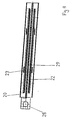
- inserts 24 of Ferrotron ® are shown. These inserts that are shown in three views, once again enlarged, in Figure 6, are of a non-conductive magnetic material and serve to amplify the electromagnetic alternating field generated by the inductor 22 locally in the immediate environment of the pressure element 23, so locally inducing greater energy in area shown enlarged in Figure 1 and thereby a greater amount of heat is applied.
- Figure 4 shows a plan view of the sealing surface of the sealing jaw according to the invention.
- the inductor 22 is clearly evident, which is received in the sealing jaw body 20 with its connector 28. Also evident are the pressure elements 23, two of which are arranged on each side of the inductor rods 22.
- the sealing jaw body 20 has a recess 29 between the two inductor rods 22 that is provided to receive a separating or cutting device in order to cut off the packaging tube between the two right angle sealing seams formed by the inductor rods 22.
Landscapes
- Engineering & Computer Science (AREA)
- Mechanical Engineering (AREA)
- Package Closures (AREA)
- Glass Compositions (AREA)
- Seal Device For Vehicle (AREA)
- Materials For Medical Uses (AREA)
- Lining Or Joining Of Plastics Or The Like (AREA)
Abstract
Description
- The present invention relates to a sealing jaw for manufacturing a sealing seam in a heat-sealable packaging material. The invention furthermore relates to an induction sealing device with a sealing jaw and to a packaging machine with induction sealing device.
- Many flowable food products such as, for example, fruit juice, pasteurised or UHT milk, wine, tomato sauce and so forth are purchased in packages that are manufactured from sterilised packaging material.
- Cuboidal milk packages are known that are formed by folding and sealing laminated packaging material with a multi-layered structure that has a fibrous layer, for example, paper, that is covered on both sides with layers of heat-sealable plastics material, for example, polyethylene. In many applications, in particular in the case of sterile packages of products with very long shelf-life such as, for example, orange juice or tomato sauce, a packaging material is generally used that has a barrier layer, for example, an aluminium layer, that is applied to a layer of heat-sealable plastics material, and is itself in turn covered with another layer of heat-sealable plastics material.
- Such packages are typically manufactured and filled on fully automated tubular bag packaging machines. The packaging material web is sterilised in the packaging machine, for example, by the application of a chemical sterilising agent such as, for example, a hydrogen peroxide solution. The chemical sterilising agent is removed after sterilising. This can be done, for example, by vaporising the agent by heating the surface of the web. The sterilised packaging material is then kept in a closed, sterile environment and is folded and sealed in the longitudinal direction in order to form a continuous tubular bag.
- This tubular bag is moved continuously in a first, usually vertical direction, is filled with the sterilised or sterile processed foodstuffs, and is then gripped by two pairs of jaws that heat and press the packaging material so that surface melting of adjacent thermoplastic layers is obtained in order to produce a fluid-tight weld. This right-angle weld is frequently also referred to as a right-angle sealing seam. For welding or sealing in this manner, so-called heating or sealing jaws are usually used that receive the packaging material to be sealed in between them and can press together at the same time as being heated, such that they melt the plastics layers that are pressed together between the sealing jaws and are lying beside one another, and form a sealed and thus a mechanically strong weld point. The pair of jaws can be formed either by two sealing jaws that both have a respective heating device, or just a single sealing jaw can be used that is pressed against a counter-jaw that serves as a thrust bearing.
- Sealing jaws are often used that have thin metal strips that are arranged on an insulating material, usually a ceramic material. In order to heat the metal strips, a short current pulse is conducted through the strips, which are thereby very rapidly heated to high temperatures. The heat generated in the metallic strips is transferred to the packaging material because of the direct contact connection, so because of the pressure that is exerted by the pair of jaws, layers of packaging that touch are fused together.
- The sealing jaws usually have two approximately parallel heating strips that produce two corresponding right-angle sealing seams, so with the aid of a cutting or separating device, the packaging material can be separated between the two right-angle sealing seams in order to obtain individual, sealed packages.
- As described hereinabove, the section of the packaging tube that is clamped between the pair of jaws is melted by the heating device attached to at least one of the jaws, so the two layers of heat-sealable plastics material that are held firmly between the jaws melt locally.
- Where a packaging material is used with an electrically conductive layer such as, for example, aluminium, the packaging material can also be sealed by using a so-called induction heating process wherein when the tube is pressed together by the jaws, an eddy current is induced in the aluminium layer in order to locally heat the aluminium layer and thereby to locally melt the heat-sealable layers that are adjacent to the aluminium layer.
- In these instances the heating device for the sealing jaw is formed by an inductor to which a high frequency voltage can be applied. The inductor is usually composed of one or more induction bars that are manufactured from electrically conductive material and extend parallel to the right-angle sealing seam to be produced. After the tubular packaging material has been clamped between the jaws fitted with inductors, an eddy current can be induced by means of the inductor in the tubular packaging material, and the material is heated to the necessary temperature for sealing. In this configuration, the other jaw usually does not have an inductor, but simply has pressure plates, usually of an elastomeric material, that cooperate with the induction bars.
- Such a sealing jaw with an induction device is known, for example, from WO 00/20279.
- When filling with flowable foodstuffs that contain small solid particles such as, for example, pips or fibres (of fruit pulp) it may happen that the solid particles are found between the jaws during melting of the right-angle sealing seam. This can lead to the right-angle sealing seam being less durable, or in the worst case even leaking from the outset. Such a faulty right-angle sealing seam is usually not noticed immediately during the packaging process, however. The leakage occurring is usually so slight that initially the packaged product does not leak from the package. Nevertheless, bacteria present in the environment go through the faulty right-angle sealing seam into the pruduct. This can lead to fermentation and decay processes in food products, whereby the pressure within the package significantly increases and sooner or later the right-angle sealing seam bursts. Even when this affects only a proportion of less than 0.1% of packages using the conventional sealing procedure, a defective right-angle sealing seam can have considerable disadvantageous consequences, in particular, when as is often the case the completed packages are placed on pallets in large numbers. If a right-angle sealing seam is leaking, the contents of the faulty package leak over all the packages lying below it, so often even the undamaged packaged are virtually unsaleable because of their soiled outsides.
- The object of the present invention is therefore to provide a sealing jaw with which a sealed and durable sealing seam can be produced, even when solid components of the in-filled product are trapped between the jaws that have to be moved towards one another.
- This object is solved according to the invention by means of a sealing jaw with a sealing surface that is provided in order to come into contact with the heat-sealable material, and a rod or bar-shaped heating device that is provided in order to heat up the heat-sealable material, wherein a pressure element is provided on the sealing surface, projecting above said sealing surface, and distanced from the heating device. By means of this additional pressure element it is ensured that solid components such as, for example, fruit pulp, possibly found in the area of the right-angle sealing seam, are reliably divided through. Moreover, by means of the additional pressure element, the heat sealed seam is somewhat wider at the place on which the pressure element is positioned, which itself results in a reliable and durable seam even when there are solids present in the right-angle sealing seam.
- It has been shown that the pressure element is advantageously also rod or bar-shaped and is arranged substantially parallel to the heating device. This results in strengthening over a whole section of the sealing seam, whereby the leakage rate can be further reduced.
- In numerous tests, it has been established that preferably the heating device and the pressure element are distanced apart from one another by at least 0.1 mm, preferably between 0.25 mm and 3 mm, particularly preferably between 0.5 mm and 1.5 mm.
- The heating device can be configured, in principle, in many different ways. It can thus be composed of a thin wire to which, if necessary, a direct current can be applied in order to briefly heat the wire to a high temperature. It has been shown, however, that when packaging material with an electrically conductive layer is used, it is particularly advantageous when the heating device is an inductor. In this case, a high voltage is applied to the inductor so that an eddy current can be induced in the electrically conductive layer of the packaging material, that in turn results in local heating of the corresponding heat-sealable layers. In this case, the pressure element should be composed of a non-conductive material. A particularly durable sealing seam is obtained when the pressure element is completely separate from the heating device, that is to say itself is neither heated nor induces an eddy current.
- The pressure element is preferably composed of a very strong and very rigid material. For example, a ceramic material or a thermoplastic material can be considered. Polyaryletherketones, and particularly in this case polyether-etherketone (PEEK) have proved to be particularly suitable. Polyaryletherketones belong to those plastics that are very strong and very rigid in a broad temperature range. Advantageously, fibre-reinforced PEEK is used to which glass and/or plastics fibres, and possibly anti-friction additives such as PTFE and graphite are added. The materials described have proved particularly advantageous with respect to durability, and in particular with respect to the quality of the sealing seam to be produced.
- It has been shown that the pressure element does not absolutely have to be arranged over the whole length of the heating device. In order to strengthen the sealing seam, instead a pressure element length of between 2 and 30 mm, preferably between 4 and 15 mm, particularly preferably between 7 and 9 mm, is advantageous. The length of the pressure element is measured parallel to the sealing seam to be produced.
- Although the pair of jaws for producing the sealing seam is generally pressed together very rapidly, this nevertheless results in redistribution of the flowable product within the packaging tube. In particular shortly before touching the two packaging webs, because of the engagement of the jaws, the flow velocity in the region of the jaws increases considerably. By means of provision of the pressure element according to the invention, which projects over the sealing surface, an area is defined that has a smaller cross-section during closing of the jaws than the adjacent areas upon which no pressure element is arranged. This leads to an accelerated flowing away of solid components in the flowable product, so although the pressure element is not arranged along the whole heating device, the quality of the sealing seam can be increased still further.
- The packaging webs used are usually provided with fold lines at which the packaging material is folded for producing the generally cuboidal package. Usually, longitudinal and right-angle fold lines are provided that form, inter alia, the right-angle and longitudinal edges of the cuboidal package in the case of the finished, filled and folded package.
- Advantageously, the pressure element is substantially arranged such that it meets with the fold line running in the longitudinal direction when the packaging material is sealed, as the probability of a leak is at its greatest at this point.
- In a particularly preferred embodiment, two pressure elements are provided that are preferably arranged such that during hot melting of the packaging material, they respectively meet on a fold line running in the longitudinal direction.
- In order to manufacture the package, after the right-angle sealing seam has been manufactured it is generally folded over by 180°. The tabs produced are then bent over in the direction of the base surface of the package.
- This, however, results in there being areas in the proximity of the fold lines where the packaging material is bent over by 180°. This can possibly lead to damage to the cellular material or barrier layer. It has therefore already been proposed in EP 0 936 150 to interrupt the fold lines in the areas that are bent by 180° when folded up together, and to replace them with two auxiliary fold lines slightly offset with respect to the actual fold line. The result of this is that the radius of bending is greater, and the danger of breaking the cellular material is minimised.
- These auxiliary fold lines are, however, arranged in the direct proximity of the planned heat sealed seam. As the auxiliary fold lines of the packaging material used project slightly above the surface of the packaging material, in certain circumstances solid components in the product to be packaged can be clamped in during the sealing, so the sealing seam manufactured with the sealing units of the prior art do not produce a durable join. Tests have shown that in the case of leaky packages, the leak point is very often in the region of the auxiliary lines.
- Thus, in accordance with the invention, the pressure element is arranged such that when the jaws are brought together it meets with the packaging material in the immediate environment of the double auxiliary line. By means of this measure, in the case of the packaging material described, the rejection rate due to defective right-angle sealing seams is clearly reduced.
- It has been shown that the length of the pressure element advantageously corresponds to approximately the length of the auxiliary lines.
- A further particularly advantageous embodiment of the sealing jaw proposes that two, rod or bar-shaped heating devices are provided. In this way two sealing seams can be produced at once. Advantageously a cutting or separating device, or at least an aperture for a cutting or separating device, is provided between the two heating devices. The welded packaging tube can be detached between the two right-angle seams using the cutting or separating device, in order to form individual packages.
- Advantageously, at least one pressure element, preferably two pressure elements, is/are assigned to each heating device. As each heating device produces an individual heat sealing seam, by means of provision of the pressure element according to the invention, the quality of the heat sealing seam can be increased. If possible, the pressure elements should be arranged such that during hot melting all the pressure elements meet with fold lines running in the longitudinal direction, which are preferably embossed lines.
- In a further, particularly advantageous embodiment, the ratio of the length of the heating device to the length of the pressure element is between 5:1 and 25:1, preferably between 10:1 and 20:1, particularly preferably approximately 15:1.
- A further improvement in the sealing seam can be obtained in that the heating device is surrounded in a section by a layer of a magnetic material, and the pressure element is arranged in this section. By means of the magnetic material, the energy applied by the inductor to the electrically conductive packaging material layer is locally increased. This measure too results in the sealing seam widening somewhat, so in the area where the pressure element according to the invention is arranged, an extremely reliable and durable join occurs.
- The magnetic material can be selected from a whole range of materials that amplify the induction effect. A non-conductive material is used particularly preferably in this case. For example, Ferrotron® can be used.
- In a further, particularly preferred embodiment, the pressure element can be displaced or adjusted in the longitudinal direction of the sealing jaw. In this way one and the same sealing jaw can be optimally adjusted to different packages with differently arranged fold lines, so during coming into engagement with the packaging material, the pressure element meets with an embossed line running in the longitudinal direction.
- The present invention also relates to an induction sealing device for heat-sealing packaging material. The present invention moreover also relates to a packaging machine wherein flowable materials are infilled into a tube formed from a web of packaging material provided with embossed lines, the tube is provided with a right angle seam in a sealing unit, and the tube is detached in the region of the right-angle sealing seam.
- Further advantages, features and possibilities for application will be evident from the following description of a preferred embodiment, and from the attached drawings. There is shown, in:
- Figure 1
- a perspective view of a tubular bag package,
- Figure 2
- a view of the packaging material for manufacturing the tubular bag package of Figure 1, with the fold lines indicated,
- Figure 3
- a view of the sealing jaw according to the invention in an exploded view,
- Figure 4
- a plan view of the sealing jaw according to the invention of Figure 3,
- Figure 5
- a side view, a view from above and a perspective view of a pressure element according to the invention, and
- Figure 6
- a side view, a plan view and a perspective view of an insert.
- In Figure 1 there is shown a known tubular bag package 1 as serves, for example, for receiving milk. In order to manufacture such a package, laminated packaging material in the form of a web with previously applied embossed fold lines, as is shown in Figure 2, is supplied continuously to a packaging machine. The web is sterilised and then bent and sealed in the longitudinal direction so that it forms a tube or a pipe of packaging material. The sealing seam running in the longitudinal direction is not evident in Figure 1, as it is located at the rear of the package.
- The packaging tube forms an extension of the sterile chamber and is continuously filled with sterile or sterilely treated flowable food products. The tube sealed in the longitudinal direction is then clamped between pairs of sealing jaws, which seal the tube in the right angle direction. The right angle sealing seams have the
reference numeral 19 in Figure 1. For better understanding, in Figure 1 and Figure 2 the same positions and lines are provided with the same reference numerals. In Figure 1, thefront side 2 and theside wall 3 of the tubular bag package can be seen. Furthermore, thelongitudinal edges front side 2 of the tubular bag package 1 are shown. The corresponding embossed lines are shown in Figure 2. Thefront surface 2 is delimited by the comer points 4, 5, 6 and 7. - Furthermore, in Figures 1 and 2, the upper and lower
end fold lines spout 15 and a pouringfold line 14. After the right-angle sealing seam 19 has been applied to the package 1 with the aid of the sealing jaws, the right-angle sealing seam is folded over along theline 12. This results in the packaging material being folded over in the region of thefold seam 12 by 180° in a first direction. In this way tensile stress is produced in the sterile material. - After the lower end of the package has been folded flat on the base of the package, the triangular tabs are also folded flat on the base. The material in the area shown enlarged in Figure 1 is thus bent over a second time by 180° in a second direction. In order to somewhat reduce the material stress linked to this, often the lower
embossed fold line 12 is interrupted in that in the area where the lowerembossed fold line 12 and the side embossedfold line 10 would intersect, and instead two auxiliaryembossed fold lines 17, 18 are applied that run parallel to one another, and are somewhat offset with respect to the lower end embossedfold line 12. This has the advantage that in this area, the radius of curvature is somewhat increased so that breakage of material can be effectively prevented. - All the embossed fold lines shown in Figure 2 are, however, generally configured such that they form raised areas on the inside of the packaging material. In order to apply the right-angle sealing seams 19, the tube must be pressed together with the aid of appropriate jaws. The additional raised areas on the inside of the packaging material because of the auxiliary
embossed fold lines 17, 18, layers of packaging material opposite one another touch initially at this point. It can thus happen that solid particles contained in the flowable food product to be infilled such as, for example, fruit pulp fibres or pips, are trapped between the embossed fold lines. If the right-angle sealing seam is then formed with the aid of a sealing unit, in certain circumstances the solid particles trapped between the auxiliary embossed fold lines can prevent a continuous right-angle sealing seam, which can involve the disadvantages described hereinabove. - A sealing jaw according to the invention, and parts thereof, are shown in Figures 3 and 5.
- Figure 3 shows an embodiment of a sealing jaw in an exploded view. The sealing
jaw body 20, which can be fitted to a holder with the aid of thescrews jaw body 20 there is located a so-called core that serves to amplify the electromagnetic field generated by theinductor 22. Theinductor 22 is composed of two rod-shaped electrical conductors joined to one another, with corresponding terminals. This inductor serves as a heating device. If a high voltage is applied to theinductor 22 at theelectrical connection terminals 28, the electromagnetic alternating field generated by theinductor 22 is amplified by thecore 21 and generates eddy currents in the electrically conductive layer of the packaging material, and thus heats this layer. - As the electrically conductive layer in the packaging material is usually very thin, heating of the packaging material is sufficient to melt the heat-sealable layers that surround the electrically conductive layer.
- A
ceramic insert 23 is furthermore shown that forms the pressure element according to the invention. Theceramic insert 23 that is shown in three different views in Figure 5 has a substantially U-shaped cross-section and is arranged such that the two rod-shaped inductors are arranged between its two arms. The two tips of the U-shaped arms are configured such that they somewhat project above the surface of the sealingjaw body 20. They are therefore configured with rounded end faces as can be seen at the top in Figure 5, in order to prevent damaging the packaging material during the clamping procedure. - The two arms of the U of the ceramic insert shown in Figures 3 and 5 each form a pressure element, both of which elements project above the sealing
jaw body 20. - The pressure elements are arranged such that they come into contact with the packaging web in the area shown enlarged in Figure 1. This is substantially the area in which the imaginary extension of the longitudinal embossed fold line intersects the extension of the lower end embossed fold line.
- In addition, inserts 24 of Ferrotron ® are shown. These inserts that are shown in three views, once again enlarged, in Figure 6, are of a non-conductive magnetic material and serve to amplify the electromagnetic alternating field generated by the
inductor 22 locally in the immediate environment of thepressure element 23, so locally inducing greater energy in area shown enlarged in Figure 1 and thereby a greater amount of heat is applied. - In Figure 3 further inserts 25 of Ferrotron ® are shown that are arranged on the ends of the inductor bars 22. These simply serve to amplify the field induced on the ends as the eddy current induced must inevitably be closed, so without using the Ferrotron inserts 25 in the area of the ends of the inductor rods, somewhat less magnetic energy would be induced in the packaging web.
- Figure 4 shows a plan view of the sealing surface of the sealing jaw according to the invention. The
inductor 22 is clearly evident, which is received in the sealingjaw body 20 with itsconnector 28. Also evident are thepressure elements 23, two of which are arranged on each side of theinductor rods 22. - The sealing
jaw body 20 has arecess 29 between the twoinductor rods 22 that is provided to receive a separating or cutting device in order to cut off the packaging tube between the two right angle sealing seams formed by theinductor rods 22. -
- 1.
- tubular bag package
- 2.
- large side wall panel
- 3.
- small side wall panel
- 4.
- left, lower comer point
- 5.
- right, lower comer point
- 6.
- left, upper comer point
- 7.
- right, upper comer point
- 8.
- lower right-angle edge and lower right-angle fold line
- 9.
- upper right-angle edge and upper right-angle fold line
- 10.
- left longitudinal edge and left longitudinal fold line
- 11.
- right longitudinal edge and right longitudinal fold line
- 12.
- lower end fold line
- 13.
- upper end fold line
- 14.
- pouring fold line
- 15.
- upper tab fold line
- 16.
- lower tab fold line
- 17.
- upper auxiliary fold line
- 18.
- lower auxiliary fold line
- 19.
- right-angle sealing seam
- 20.
- sealing jaw body
- 21.
- core
- 22.
- inductor
- 23.
- pressure element
- 24/25.
- inserts
- 26/27.
- screws
- 28.
- electrical terminals
- 29.
- recess
Claims (16)
- Sealing jaw for manufacturing a sealing seam (19) in a heat-sealable material of a package with a sealing surface that is provided for coming into contact with the heat-sealable material, and a rod or bar-shaped heating heating device that is provided for heating the heat-sealable material, characterised in that a pressure element (23) is provided on the sealing surface, projecting above the sealing surface and at a distance from the heating device (22).
- Sealing jaw according to claim 1, characterised in that the pressure element (23) is rod or bar-shaped and extends substantially parallel to the heating device (22).
- Sealing jaw according to claim 1 or 2, characterised in that the heating device (22) and the pressure element (23) are distanced apart from one another by at least 0.1 mm, preferably between 0.25 mm and 3 mm, particularly preferably between 0.5 mm and 1.5 mm.
- Sealing jaw according to one of claims 1 to 3, characterised in that the heating device (22) is provided with an inductor and the pressure element (23) is composed of a non-conductive material.
- Sealing jaw according to one of claims 1 to 4, characterised in that the pressure element (23) is composed of a ceramic material or of a thermoplastic material, preferably of PEEK.
- Sealing jaw according to one of claims 1 to 5, characterised in that the pressure element (23) has a length between 2 and 30 mm, preferably between 4 and 15 mm, particularly preferably between 7 and 9 mm.
- Sealing jaw according to one of claims 1 to 6, characterised in that two pressure elements (23) are provided.
- Sealing jaw according to one of claims 1 to 7, characterised in that two rod or bar-shaped heating devices are provided.
- Sealing jaw according to claim 7, characterised in that a cutting or separating device or an aperture for a cutting or separating device is provided between the two heating devices.
- Sealing jaw according to claim 8 or 9, characterised in that each heating device is allocated at least one pressure element (23), preferably two pressure elements (23).
- Sealing jaw according to one of claims 1 to 10, characterised in that the ratio of the length of the heating device to the length of the pressure element (23) is between 5:1 and 25:1, preferably between 10:1 and 20:1, particularly preferably approximately 15:1.
- Sealing jaw according to one of claims 4 to 11, characterised in that the heating device is surrounded in a section by a layer of a non-magnetic material (24, 25) and the pressure element (23) is arranged in this section.
- Sealing jaw according to claim 12, characterised in that the insert is composed of a non-conductive material, preferably of Ferrotron (24, 25).
- Sealing jaw according to one of claims 1 to 13, characterised in that the pressure element (23) can be displaced in the longitudinal direction of the sealing jaw.
- Induction sealing device for heat sealing packaging material, with a sealing jaw according to one of claims 4 to 14 that is provided to produce a sealing seam by pressing and heating heat-sealable packaging material between the sealing jaw and a counter jaw.
- Packaging machine in which flowable material is infilled into a tube (1) formed from a material web of packaging material provided with fold lines (12, 13), the tube (1) is provided with a right-angle sealing seam (19) in a sealing unit, and the tube is detached in the area of the right-angle sealing seam (19), characterised in that the sealing unit is provided with a sealing jaw according to one of claims 1 to 14.
Priority Applications (14)
| Application Number | Priority Date | Filing Date | Title |
|---|---|---|---|
| ES02023851T ES2266382T3 (en) | 2002-10-24 | 2002-10-24 | WELDING GRIP. |
| DE2002613610 DE60213610T2 (en) | 2002-10-24 | 2002-10-24 | sealing jaw |
| EP20020023851 EP1413520B1 (en) | 2002-10-24 | 2002-10-24 | Sealing jaw |
| AT02023851T ATE334885T1 (en) | 2002-10-24 | 2002-10-24 | SEALING JAW |
| KR1020057004236A KR20050083686A (en) | 2002-10-24 | 2003-09-19 | Sealing jaw |
| BRPI0315581-1B1A BR0315581B1 (en) | 2002-10-24 | 2003-09-19 | SEALING JAW |
| AU2003275974A AU2003275974A1 (en) | 2002-10-24 | 2003-09-19 | Sealing jaw |
| US10/532,437 US7348525B2 (en) | 2002-10-24 | 2003-09-19 | Sealing jaw |
| PCT/EP2003/010452 WO2004037651A1 (en) | 2002-10-24 | 2003-09-19 | Sealing jaw |
| EP03809264A EP1554178A1 (en) | 2002-10-24 | 2003-09-19 | Sealing jaw |
| JP2004545773A JP4381308B2 (en) | 2002-10-24 | 2003-09-19 | Sealing jaw |
| RU2005115841A RU2348838C2 (en) | 2002-10-24 | 2003-09-19 | Packaging machine sealing jaw |
| MXPA05004200A MXPA05004200A (en) | 2002-10-24 | 2003-09-19 | Sealing jaw. |
| CNB038245663A CN100519349C (en) | 2002-10-24 | 2003-09-19 | Sealing jaw and packing machine |
Applications Claiming Priority (1)
| Application Number | Priority Date | Filing Date | Title |
|---|---|---|---|
| EP20020023851 EP1413520B1 (en) | 2002-10-24 | 2002-10-24 | Sealing jaw |
Publications (2)
| Publication Number | Publication Date |
|---|---|
| EP1413520A1 true EP1413520A1 (en) | 2004-04-28 |
| EP1413520B1 EP1413520B1 (en) | 2006-08-02 |
Family
ID=32050018
Family Applications (2)
| Application Number | Title | Priority Date | Filing Date |
|---|---|---|---|
| EP20020023851 Expired - Lifetime EP1413520B1 (en) | 2002-10-24 | 2002-10-24 | Sealing jaw |
| EP03809264A Withdrawn EP1554178A1 (en) | 2002-10-24 | 2003-09-19 | Sealing jaw |
Family Applications After (1)
| Application Number | Title | Priority Date | Filing Date |
|---|---|---|---|
| EP03809264A Withdrawn EP1554178A1 (en) | 2002-10-24 | 2003-09-19 | Sealing jaw |
Country Status (13)
| Country | Link |
|---|---|
| US (1) | US7348525B2 (en) |
| EP (2) | EP1413520B1 (en) |
| JP (1) | JP4381308B2 (en) |
| KR (1) | KR20050083686A (en) |
| CN (1) | CN100519349C (en) |
| AT (1) | ATE334885T1 (en) |
| AU (1) | AU2003275974A1 (en) |
| BR (1) | BR0315581B1 (en) |
| DE (1) | DE60213610T2 (en) |
| ES (1) | ES2266382T3 (en) |
| MX (1) | MXPA05004200A (en) |
| RU (1) | RU2348838C2 (en) |
| WO (1) | WO2004037651A1 (en) |
Cited By (10)
| Publication number | Priority date | Publication date | Assignee | Title |
|---|---|---|---|---|
| WO2007008131A3 (en) * | 2005-07-08 | 2007-03-29 | Tetra Laval Holdings & Finance | Device and method for transverse sealing |
| US9174754B2 (en) | 2007-06-28 | 2015-11-03 | Tetra Laval Holdings & Finance S.A. | Induction sealing device for heat sealing packaging material for producing sealed packages of pourable food products |
| WO2015189253A1 (en) * | 2014-06-12 | 2015-12-17 | Tetra Laval Holdings & Finance S.A. | An induction heating device |
| EP2984903B1 (en) * | 2013-04-10 | 2020-11-04 | Tetra Laval Holdings & Finance S.A. | Induction sealing device and method for manufacturing an induction sealing device |
| US11534985B2 (en) | 2016-05-02 | 2022-12-27 | Tetra Laval Holdings & Finance S.A. | Induction sealing system |
| US11548238B2 (en) | 2018-09-10 | 2023-01-10 | Tetra Laval Holdings & Finance S.A. | Method for forming a tube and a method and a packaging machine for forming a package |
| EP4205956A1 (en) * | 2021-12-30 | 2023-07-05 | Rohr, Inc. | Induction welding with an electromagnetic field concentrator |
| US11820540B2 (en) | 2018-09-11 | 2023-11-21 | Tetra Laval Holdings & Finance S.A. | Packaging apparatus for forming sealed packages |
| US12122547B2 (en) | 2019-02-05 | 2024-10-22 | Tetra Laval Holdings & Finance S.A. | Induction heat sealing device and a method for transversally seal a tube of packaging material |
| US12522394B2 (en) | 2021-02-15 | 2026-01-13 | Tetra Laval Holdings & Finance S.A. | Method for assessing quality of a transversal sealing of a food package |
Families Citing this family (25)
| Publication number | Priority date | Publication date | Assignee | Title |
|---|---|---|---|---|
| DE102005054489B4 (en) * | 2005-11-16 | 2008-01-31 | Keiper Gmbh & Co.Kg | Fitting for a vehicle seat |
| EP2113371A1 (en) | 2008-04-29 | 2009-11-04 | Tetra Laval Holdings & Finance SA | Sealing jaw for producing sealed packages of a food product |
| US8740458B2 (en) * | 2010-05-25 | 2014-06-03 | Frito-Lay North America, Inc. | Easy open bag |
| MX341707B (en) * | 2011-07-11 | 2016-08-31 | Å&R Carton Lund Ab | Apparatus and method for manufacturing of containers. |
| CN104508473B (en) | 2012-05-29 | 2017-10-13 | 健康诊断实验室有限公司 | Composition and method for the gel electrophoresis with calibrated in situ |
| KR20160055850A (en) * | 2013-09-13 | 2016-05-18 | 테트라 라발 홀딩스 앤드 피낭스 소시에떼아노님 | Induction sealing device and method for manufacturing an induction sealing device |
| FI125452B (en) * | 2014-02-20 | 2015-10-15 | Lamican Oy | Induction welding system, method and device |
| WO2015158502A1 (en) | 2014-04-16 | 2015-10-22 | Tetra Laval Holdings & Finance S.A. | Induction sealing device and method of sealing a packaging material using said induction sealing device |
| DE102014107157A1 (en) * | 2014-05-21 | 2015-11-26 | Elopak Systems Ag | Method and apparatus for heat-sealing multiple layers of a laminate |
| EP3224020B1 (en) * | 2014-11-24 | 2020-01-29 | Tetra Laval Holdings & Finance S.A. | Simplified transversal induction sealing device |
| EP3090860B1 (en) * | 2015-05-05 | 2019-09-11 | Tetra Laval Holdings & Finance S.A. | Induction heating sealing device |
| BR112018002738B1 (en) * | 2015-08-31 | 2022-01-04 | Elopak As | DEVICE AND METHOD FOR INDUCTIVE SEALING OF A PLURALITY OF STRATES OF A LAMINATED |
| BR112018010484B8 (en) * | 2015-11-27 | 2022-03-03 | Tetra Laval Holdings & Finance | Induction sealing device, method of producing an induction sealing device, and filling machine |
| US11554555B2 (en) | 2017-05-30 | 2023-01-17 | Tetra Laval Holdings & Finance S.A. | Apparatus for sealing the top of a package for a food product and system for forming and filling a food package |
| US10899082B2 (en) | 2017-07-17 | 2021-01-26 | Tetra Laval Holdings & Finance S.A. | Inductor coil for induction welding of a packaging material |
| EP3431267B1 (en) | 2017-07-18 | 2023-08-30 | Tetra Laval Holdings & Finance S.A. | Induction sealing device |
| CN107499609A (en) * | 2017-09-30 | 2017-12-22 | 江阴市意康包装制品有限公司 | One kind holds supping polybag with portable sealing device |
| CN112739528A (en) * | 2018-07-16 | 2021-04-30 | 阿科玛法国公司 | Method for welding thermoplastic material parts |
| CN109162995B (en) * | 2018-08-21 | 2021-03-30 | Tcl王牌电器(惠州)有限公司 | Lamp strip dispensing assembly jig and lamp strip dispensing assembly machine |
| RU187974U1 (en) * | 2018-09-11 | 2019-03-26 | Федеральное государственное бюджетное учреждение науки Институт проблем нефти и газа Сибирского отделения Российской академии наук | Heater for welding polymer pipes |
| US11260603B2 (en) | 2019-10-03 | 2022-03-01 | Frito-Lay America, Inc. | Heat seal jaws with asymmetric teeth |
| JP7787886B2 (en) * | 2020-11-06 | 2025-12-17 | テトラ ラバル ホールディングス アンド ファイナンス エス エイ | Induction Sealing Device |
| DE102021124797A1 (en) * | 2021-09-24 | 2023-03-30 | Ampack Gmbh | Sealing device, sealing station and method of manufacturing such a sealing device |
| WO2024035275A1 (en) * | 2022-08-12 | 2024-02-15 | Shavelkin Yuriy Alekseevich | Device for joining dissimilar materials |
| WO2026068095A1 (en) * | 2024-09-24 | 2026-04-02 | Tetra Laval Holdings & Finance S.A. | An inductor device and a connector device for inductively heating a web of packaging material, a sealing unit and a packaging machine for producing sealed packages from a web of packaging material |
Citations (7)
| Publication number | Priority date | Publication date | Assignee | Title |
|---|---|---|---|---|
| US3549440A (en) * | 1967-10-26 | 1970-12-22 | United Glass Ltd | Method for sealing a membrane to the mouth of a container utilizing induced radio frequency current |
| US4704509A (en) * | 1985-08-22 | 1987-11-03 | Tetra Pak International Ab | Induction apparatus and method for sealing of thermoplastic coated packing material |
| EP0484998A1 (en) * | 1990-10-19 | 1992-05-13 | Shikoku Kakoki Co., Ltd. | Appareil pour thermosoudage d'un matériau d'emballage tubulaire |
| EP0936150A1 (en) | 1998-02-13 | 1999-08-18 | Tetra Laval Holdings & Finance Sa | Pre-creased packaging sheet material for packaging pourable food products, and packages obtained thereby |
| WO2000020279A1 (en) | 1998-10-07 | 2000-04-13 | Tetra Laval Holdings & Finance Sa | Method of producing sealed packages containing pourable food products from a tube of packing material, and packing unit implementing such a method |
| WO2000044625A1 (en) * | 1999-02-01 | 2000-08-03 | Tetra Laval Holdings & Finance Sa | Counter rail and counter element in a sealing apparatus and method of manufacturing thereof |
| US6167681B1 (en) * | 1996-01-30 | 2001-01-02 | Tetra Laval Holdings & Finance S.A. | Sealing apparatus |
Family Cites Families (9)
| Publication number | Priority date | Publication date | Assignee | Title |
|---|---|---|---|---|
| US5208083A (en) * | 1989-11-16 | 1993-05-04 | Rohm And Haas Company | Polymer blends with enhanced properties |
| JP3332173B2 (en) * | 1993-07-09 | 2002-10-07 | 日本テトラパック株式会社 | Residual product removal device |
| SE508369C2 (en) * | 1993-10-07 | 1998-09-28 | Tetra Laval Holdings & Finance | Method and apparatus for making bag packages |
| US5673534A (en) * | 1995-06-23 | 1997-10-07 | Simple Packaging Solutions, Inc. | Reclosable storage bag |
| US5687542A (en) * | 1995-08-22 | 1997-11-18 | Medrad, Inc. | Isolation module for molding and packaging articles substantially free from contaminants |
| FR2776616B1 (en) * | 1998-03-24 | 2001-09-07 | Tetra Laval Holdings & Finance | DEVICE FOR THERMOSOLDING A TUBE OF LAMINATED PACKAGING MATERIAL FILLED WITH A FLUID FOOD PRODUCT |
| US6337471B1 (en) * | 1999-04-23 | 2002-01-08 | The Boeing Company | Combined superplastic forming and adhesive bonding |
| JP3751472B2 (en) * | 1999-05-27 | 2006-03-01 | Necディスプレイソリューションズ株式会社 | Double-sided pattern sheet metal parts and printed wiring board |
| JP5013641B2 (en) * | 2001-09-21 | 2012-08-29 | キヤノン株式会社 | Image heating apparatus and image forming apparatus |
-
2002
- 2002-10-24 DE DE2002613610 patent/DE60213610T2/en not_active Expired - Lifetime
- 2002-10-24 AT AT02023851T patent/ATE334885T1/en not_active IP Right Cessation
- 2002-10-24 ES ES02023851T patent/ES2266382T3/en not_active Expired - Lifetime
- 2002-10-24 EP EP20020023851 patent/EP1413520B1/en not_active Expired - Lifetime
-
2003
- 2003-09-19 CN CNB038245663A patent/CN100519349C/en not_active Expired - Fee Related
- 2003-09-19 KR KR1020057004236A patent/KR20050083686A/en not_active Ceased
- 2003-09-19 BR BRPI0315581-1B1A patent/BR0315581B1/en not_active IP Right Cessation
- 2003-09-19 EP EP03809264A patent/EP1554178A1/en not_active Withdrawn
- 2003-09-19 JP JP2004545773A patent/JP4381308B2/en not_active Expired - Fee Related
- 2003-09-19 US US10/532,437 patent/US7348525B2/en not_active Expired - Fee Related
- 2003-09-19 AU AU2003275974A patent/AU2003275974A1/en not_active Abandoned
- 2003-09-19 WO PCT/EP2003/010452 patent/WO2004037651A1/en not_active Ceased
- 2003-09-19 MX MXPA05004200A patent/MXPA05004200A/en active IP Right Grant
- 2003-09-19 RU RU2005115841A patent/RU2348838C2/en not_active IP Right Cessation
Patent Citations (7)
| Publication number | Priority date | Publication date | Assignee | Title |
|---|---|---|---|---|
| US3549440A (en) * | 1967-10-26 | 1970-12-22 | United Glass Ltd | Method for sealing a membrane to the mouth of a container utilizing induced radio frequency current |
| US4704509A (en) * | 1985-08-22 | 1987-11-03 | Tetra Pak International Ab | Induction apparatus and method for sealing of thermoplastic coated packing material |
| EP0484998A1 (en) * | 1990-10-19 | 1992-05-13 | Shikoku Kakoki Co., Ltd. | Appareil pour thermosoudage d'un matériau d'emballage tubulaire |
| US6167681B1 (en) * | 1996-01-30 | 2001-01-02 | Tetra Laval Holdings & Finance S.A. | Sealing apparatus |
| EP0936150A1 (en) | 1998-02-13 | 1999-08-18 | Tetra Laval Holdings & Finance Sa | Pre-creased packaging sheet material for packaging pourable food products, and packages obtained thereby |
| WO2000020279A1 (en) | 1998-10-07 | 2000-04-13 | Tetra Laval Holdings & Finance Sa | Method of producing sealed packages containing pourable food products from a tube of packing material, and packing unit implementing such a method |
| WO2000044625A1 (en) * | 1999-02-01 | 2000-08-03 | Tetra Laval Holdings & Finance Sa | Counter rail and counter element in a sealing apparatus and method of manufacturing thereof |
Cited By (13)
| Publication number | Priority date | Publication date | Assignee | Title |
|---|---|---|---|---|
| WO2007008131A3 (en) * | 2005-07-08 | 2007-03-29 | Tetra Laval Holdings & Finance | Device and method for transverse sealing |
| US8201606B2 (en) | 2005-07-08 | 2012-06-19 | Tetra Laval Holdings & Finance S.A. | Device for transverse sealing |
| US9174754B2 (en) | 2007-06-28 | 2015-11-03 | Tetra Laval Holdings & Finance S.A. | Induction sealing device for heat sealing packaging material for producing sealed packages of pourable food products |
| EP2984903B1 (en) * | 2013-04-10 | 2020-11-04 | Tetra Laval Holdings & Finance S.A. | Induction sealing device and method for manufacturing an induction sealing device |
| WO2015189253A1 (en) * | 2014-06-12 | 2015-12-17 | Tetra Laval Holdings & Finance S.A. | An induction heating device |
| US10322546B2 (en) | 2014-06-12 | 2019-06-18 | Tetra Laval Holdings & Finance S.A. | Induction heating device |
| US11534985B2 (en) | 2016-05-02 | 2022-12-27 | Tetra Laval Holdings & Finance S.A. | Induction sealing system |
| US11548238B2 (en) | 2018-09-10 | 2023-01-10 | Tetra Laval Holdings & Finance S.A. | Method for forming a tube and a method and a packaging machine for forming a package |
| US11820540B2 (en) | 2018-09-11 | 2023-11-21 | Tetra Laval Holdings & Finance S.A. | Packaging apparatus for forming sealed packages |
| US12122547B2 (en) | 2019-02-05 | 2024-10-22 | Tetra Laval Holdings & Finance S.A. | Induction heat sealing device and a method for transversally seal a tube of packaging material |
| US12240643B2 (en) | 2019-02-05 | 2025-03-04 | Tetra Laval Holdings & Finance S.A. | Induction heat sealing device and a method for transversally seal a tube of packaging material |
| US12522394B2 (en) | 2021-02-15 | 2026-01-13 | Tetra Laval Holdings & Finance S.A. | Method for assessing quality of a transversal sealing of a food package |
| EP4205956A1 (en) * | 2021-12-30 | 2023-07-05 | Rohr, Inc. | Induction welding with an electromagnetic field concentrator |
Also Published As
| Publication number | Publication date |
|---|---|
| MXPA05004200A (en) | 2005-06-08 |
| WO2004037651A1 (en) | 2004-05-06 |
| JP4381308B2 (en) | 2009-12-09 |
| CN1688483A (en) | 2005-10-26 |
| DE60213610D1 (en) | 2006-09-14 |
| US7348525B2 (en) | 2008-03-25 |
| AU2003275974A1 (en) | 2004-05-13 |
| KR20050083686A (en) | 2005-08-26 |
| DE60213610T2 (en) | 2007-10-11 |
| JP2006503762A (en) | 2006-02-02 |
| EP1554178A1 (en) | 2005-07-20 |
| CN100519349C (en) | 2009-07-29 |
| ATE334885T1 (en) | 2006-08-15 |
| RU2005115841A (en) | 2006-07-27 |
| EP1413520B1 (en) | 2006-08-02 |
| BR0315581B1 (en) | 2013-10-08 |
| BR0315581A (en) | 2005-08-30 |
| RU2348838C2 (en) | 2009-03-10 |
| ES2266382T3 (en) | 2007-03-01 |
| US20060124626A1 (en) | 2006-06-15 |
Similar Documents
| Publication | Publication Date | Title |
|---|---|---|
| EP1413520B1 (en) | Sealing jaw | |
| CN100418736C (en) | Induction sealer for heat-sealing packages | |
| EP3131739B1 (en) | Induction sealing device and method of sealing a packaging material using said induction sealing device | |
| JP6965275B2 (en) | Improved inductive seal system | |
| RU2671008C2 (en) | Induction sealing device and method for manufacturing an induction sealing device | |
| EP0796718B1 (en) | An apparatus and a method for induction sealing | |
| EP4003705B1 (en) | Production of collapsible pouches having a fitment | |
| US12428187B2 (en) | Impulse heat sealing of a heat-sealable film material | |
| EP1065145B1 (en) | Method and device for fitting pull-off tabs to pourable food product packaging material | |
| EP3090860A1 (en) | Induction heating sealing device | |
| EP3090861A1 (en) | Induction heating sealing device | |
| NL2023584B1 (en) | Impulse heat sealing of a heat-sealable film material | |
| CN120153105A (en) | Multilayer rod, sealing unit, package forming device, packaging machine, method for manufacturing a multilayer rod and method for manufacturing an induction sealing device |
Legal Events
| Date | Code | Title | Description |
|---|---|---|---|
| PUAI | Public reference made under article 153(3) epc to a published international application that has entered the european phase |
Free format text: ORIGINAL CODE: 0009012 |
|
| AK | Designated contracting states |
Kind code of ref document: A1 Designated state(s): AT BE BG CH CY CZ DE DK EE ES FI FR GB GR IE IT LI LU MC NL PT SE SK TR |
|
| AX | Request for extension of the european patent |
Extension state: AL LT LV MK RO SI |
|
| 17P | Request for examination filed |
Effective date: 20040930 |
|
| AKX | Designation fees paid |
Designated state(s): AT BE BG CH CY CZ DE DK EE ES FI FR GB GR IE IT LI LU MC NL PT SE SK TR |
|
| 17Q | First examination report despatched |
Effective date: 20050217 |
|
| GRAP | Despatch of communication of intention to grant a patent |
Free format text: ORIGINAL CODE: EPIDOSNIGR1 |
|
| GRAS | Grant fee paid |
Free format text: ORIGINAL CODE: EPIDOSNIGR3 |
|
| GRAA | (expected) grant |
Free format text: ORIGINAL CODE: 0009210 |
|
| AK | Designated contracting states |
Kind code of ref document: B1 Designated state(s): AT BE BG CH CY CZ DE DK EE ES FI FR GB GR IE IT LI LU MC NL PT SE SK TR |
|
| PG25 | Lapsed in a contracting state [announced via postgrant information from national office to epo] |
Ref country code: LI Free format text: LAPSE BECAUSE OF FAILURE TO SUBMIT A TRANSLATION OF THE DESCRIPTION OR TO PAY THE FEE WITHIN THE PRESCRIBED TIME-LIMIT Effective date: 20060802 Ref country code: IT Free format text: LAPSE BECAUSE OF FAILURE TO SUBMIT A TRANSLATION OF THE DESCRIPTION OR TO PAY THE FEE WITHIN THE PRESCRIBED TIME-LIMIT;WARNING: LAPSES OF ITALIAN PATENTS WITH EFFECTIVE DATE BEFORE 2007 MAY HAVE OCCURRED AT ANY TIME BEFORE 2007. THE CORRECT EFFECTIVE DATE MAY BE DIFFERENT FROM THE ONE RECORDED. Effective date: 20060802 Ref country code: AT Free format text: LAPSE BECAUSE OF FAILURE TO SUBMIT A TRANSLATION OF THE DESCRIPTION OR TO PAY THE FEE WITHIN THE PRESCRIBED TIME-LIMIT Effective date: 20060802 Ref country code: NL Free format text: LAPSE BECAUSE OF FAILURE TO SUBMIT A TRANSLATION OF THE DESCRIPTION OR TO PAY THE FEE WITHIN THE PRESCRIBED TIME-LIMIT Effective date: 20060802 Ref country code: SK Free format text: LAPSE BECAUSE OF FAILURE TO SUBMIT A TRANSLATION OF THE DESCRIPTION OR TO PAY THE FEE WITHIN THE PRESCRIBED TIME-LIMIT Effective date: 20060802 Ref country code: BE Free format text: LAPSE BECAUSE OF FAILURE TO SUBMIT A TRANSLATION OF THE DESCRIPTION OR TO PAY THE FEE WITHIN THE PRESCRIBED TIME-LIMIT Effective date: 20060802 Ref country code: CZ Free format text: LAPSE BECAUSE OF FAILURE TO SUBMIT A TRANSLATION OF THE DESCRIPTION OR TO PAY THE FEE WITHIN THE PRESCRIBED TIME-LIMIT Effective date: 20060802 Ref country code: FI Free format text: LAPSE BECAUSE OF FAILURE TO SUBMIT A TRANSLATION OF THE DESCRIPTION OR TO PAY THE FEE WITHIN THE PRESCRIBED TIME-LIMIT Effective date: 20060802 Ref country code: CH Free format text: LAPSE BECAUSE OF FAILURE TO SUBMIT A TRANSLATION OF THE DESCRIPTION OR TO PAY THE FEE WITHIN THE PRESCRIBED TIME-LIMIT Effective date: 20060802 |
|
| REG | Reference to a national code |
Ref country code: GB Ref legal event code: FG4D |
|
| REG | Reference to a national code |
Ref country code: CH Ref legal event code: EP |
|
| REG | Reference to a national code |
Ref country code: IE Ref legal event code: FG4D |
|
| REF | Corresponds to: |
Ref document number: 60213610 Country of ref document: DE Date of ref document: 20060914 Kind code of ref document: P |
|
| PG25 | Lapsed in a contracting state [announced via postgrant information from national office to epo] |
Ref country code: IE Free format text: LAPSE BECAUSE OF NON-PAYMENT OF DUE FEES Effective date: 20061024 |
|
| PG25 | Lapsed in a contracting state [announced via postgrant information from national office to epo] |
Ref country code: MC Free format text: LAPSE BECAUSE OF NON-PAYMENT OF DUE FEES Effective date: 20061031 |
|
| PG25 | Lapsed in a contracting state [announced via postgrant information from national office to epo] |
Ref country code: BG Free format text: LAPSE BECAUSE OF FAILURE TO SUBMIT A TRANSLATION OF THE DESCRIPTION OR TO PAY THE FEE WITHIN THE PRESCRIBED TIME-LIMIT Effective date: 20061102 Ref country code: SE Free format text: LAPSE BECAUSE OF FAILURE TO SUBMIT A TRANSLATION OF THE DESCRIPTION OR TO PAY THE FEE WITHIN THE PRESCRIBED TIME-LIMIT Effective date: 20061102 Ref country code: DK Free format text: LAPSE BECAUSE OF FAILURE TO SUBMIT A TRANSLATION OF THE DESCRIPTION OR TO PAY THE FEE WITHIN THE PRESCRIBED TIME-LIMIT Effective date: 20061102 |
|
| NLV1 | Nl: lapsed or annulled due to failure to fulfill the requirements of art. 29p and 29m of the patents act | ||
| PG25 | Lapsed in a contracting state [announced via postgrant information from national office to epo] |
Ref country code: PT Free format text: LAPSE BECAUSE OF FAILURE TO SUBMIT A TRANSLATION OF THE DESCRIPTION OR TO PAY THE FEE WITHIN THE PRESCRIBED TIME-LIMIT Effective date: 20070102 |
|
| ET | Fr: translation filed | ||
| REG | Reference to a national code |
Ref country code: CH Ref legal event code: PL |
|
| REG | Reference to a national code |
Ref country code: ES Ref legal event code: FG2A Ref document number: 2266382 Country of ref document: ES Kind code of ref document: T3 |
|
| PLBE | No opposition filed within time limit |
Free format text: ORIGINAL CODE: 0009261 |
|
| STAA | Information on the status of an ep patent application or granted ep patent |
Free format text: STATUS: NO OPPOSITION FILED WITHIN TIME LIMIT |
|
| 26N | No opposition filed |
Effective date: 20070503 |
|
| GBPC | Gb: european patent ceased through non-payment of renewal fee |
Effective date: 20061102 |
|
| PG25 | Lapsed in a contracting state [announced via postgrant information from national office to epo] |
Ref country code: GB Free format text: LAPSE BECAUSE OF NON-PAYMENT OF DUE FEES Effective date: 20061102 |
|
| PG25 | Lapsed in a contracting state [announced via postgrant information from national office to epo] |
Ref country code: GR Free format text: LAPSE BECAUSE OF FAILURE TO SUBMIT A TRANSLATION OF THE DESCRIPTION OR TO PAY THE FEE WITHIN THE PRESCRIBED TIME-LIMIT Effective date: 20061103 |
|
| PG25 | Lapsed in a contracting state [announced via postgrant information from national office to epo] |
Ref country code: EE Free format text: LAPSE BECAUSE OF FAILURE TO SUBMIT A TRANSLATION OF THE DESCRIPTION OR TO PAY THE FEE WITHIN THE PRESCRIBED TIME-LIMIT Effective date: 20060802 |
|
| PG25 | Lapsed in a contracting state [announced via postgrant information from national office to epo] |
Ref country code: LU Free format text: LAPSE BECAUSE OF NON-PAYMENT OF DUE FEES Effective date: 20061024 Ref country code: TR Free format text: LAPSE BECAUSE OF FAILURE TO SUBMIT A TRANSLATION OF THE DESCRIPTION OR TO PAY THE FEE WITHIN THE PRESCRIBED TIME-LIMIT Effective date: 20060802 |
|
| PG25 | Lapsed in a contracting state [announced via postgrant information from national office to epo] |
Ref country code: CY Free format text: LAPSE BECAUSE OF FAILURE TO SUBMIT A TRANSLATION OF THE DESCRIPTION OR TO PAY THE FEE WITHIN THE PRESCRIBED TIME-LIMIT Effective date: 20060802 |
|
| REG | Reference to a national code |
Ref country code: FR Ref legal event code: PLFP Year of fee payment: 15 |
|
| PGFP | Annual fee paid to national office [announced via postgrant information from national office to epo] |
Ref country code: FR Payment date: 20160919 Year of fee payment: 15 |
|
| PGFP | Annual fee paid to national office [announced via postgrant information from national office to epo] |
Ref country code: ES Payment date: 20160913 Year of fee payment: 15 |
|
| PGFP | Annual fee paid to national office [announced via postgrant information from national office to epo] |
Ref country code: DE Payment date: 20161018 Year of fee payment: 15 |
|
| PGFP | Annual fee paid to national office [announced via postgrant information from national office to epo] |
Ref country code: IT Payment date: 20161024 Year of fee payment: 15 |
|
| REG | Reference to a national code |
Ref country code: DE Ref legal event code: R119 Ref document number: 60213610 Country of ref document: DE |
|
| REG | Reference to a national code |
Ref country code: FR Ref legal event code: ST Effective date: 20180629 |
|
| PG25 | Lapsed in a contracting state [announced via postgrant information from national office to epo] |
Ref country code: DE Free format text: LAPSE BECAUSE OF NON-PAYMENT OF DUE FEES Effective date: 20180501 |
|
| PG25 | Lapsed in a contracting state [announced via postgrant information from national office to epo] |
Ref country code: FR Free format text: LAPSE BECAUSE OF NON-PAYMENT OF DUE FEES Effective date: 20171031 |
|
| PG25 | Lapsed in a contracting state [announced via postgrant information from national office to epo] |
Ref country code: IT Free format text: LAPSE BECAUSE OF NON-PAYMENT OF DUE FEES Effective date: 20171024 |
|
| REG | Reference to a national code |
Ref country code: ES Ref legal event code: FD2A Effective date: 20181221 |
|
| PG25 | Lapsed in a contracting state [announced via postgrant information from national office to epo] |
Ref country code: ES Free format text: LAPSE BECAUSE OF NON-PAYMENT OF DUE FEES Effective date: 20171025 |