EP1413371A2 - Coil material feeding apparatus - Google Patents
Coil material feeding apparatus Download PDFInfo
- Publication number
- EP1413371A2 EP1413371A2 EP03256578A EP03256578A EP1413371A2 EP 1413371 A2 EP1413371 A2 EP 1413371A2 EP 03256578 A EP03256578 A EP 03256578A EP 03256578 A EP03256578 A EP 03256578A EP 1413371 A2 EP1413371 A2 EP 1413371A2
- Authority
- EP
- European Patent Office
- Prior art keywords
- feeding
- coil material
- feeding apparatus
- rollers
- coil
- Prior art date
- Legal status (The legal status is an assumption and is not a legal conclusion. Google has not performed a legal analysis and makes no representation as to the accuracy of the status listed.)
- Granted
Links
Images


Classifications
-
- B—PERFORMING OPERATIONS; TRANSPORTING
- B21—MECHANICAL METAL-WORKING WITHOUT ESSENTIALLY REMOVING MATERIAL; PUNCHING METAL
- B21K—MAKING FORGED OR PRESSED METAL PRODUCTS, e.g. HORSE-SHOES, RIVETS, BOLTS OR WHEELS
- B21K27/00—Handling devices, e.g. for feeding, aligning, discharging, Cutting-off means; Arrangement thereof
- B21K27/02—Feeding devices for rods, wire, or strips
- B21K27/04—Feeding devices for rods, wire, or strips allowing successive working steps
-
- B—PERFORMING OPERATIONS; TRANSPORTING
- B21—MECHANICAL METAL-WORKING WITHOUT ESSENTIALLY REMOVING MATERIAL; PUNCHING METAL
- B21D—WORKING OR PROCESSING OF SHEET METAL OR METAL TUBES, RODS OR PROFILES WITHOUT ESSENTIALLY REMOVING MATERIAL; PUNCHING METAL
- B21D43/00—Feeding, positioning or storing devices combined with, or arranged in, or specially adapted for use in connection with, apparatus for working or processing sheet metal, metal tubes or metal profiles; Associations therewith of cutting devices
- B21D43/02—Advancing work in relation to the stroke of the die or tool
- B21D43/021—Control or correction devices in association with moving strips
- B21D43/022—Loop-control
-
- B—PERFORMING OPERATIONS; TRANSPORTING
- B21—MECHANICAL METAL-WORKING WITHOUT ESSENTIALLY REMOVING MATERIAL; PUNCHING METAL
- B21C—MANUFACTURE OF METAL SHEETS, WIRE, RODS, TUBES, PROFILES OR LIKE SEMI-MANUFACTURED PRODUCTS OTHERWISE THAN BY ROLLING; AUXILIARY OPERATIONS USED IN CONNECTION WITH METAL-WORKING WITHOUT ESSENTIALLY REMOVING MATERIAL
- B21C47/00—Winding-up, coiling or winding-off metal wire, metal band or other flexible metal material characterised by features relevant to metal processing only
- B21C47/16—Unwinding or uncoiling
- B21C47/18—Unwinding or uncoiling from reels or drums
-
- B—PERFORMING OPERATIONS; TRANSPORTING
- B21—MECHANICAL METAL-WORKING WITHOUT ESSENTIALLY REMOVING MATERIAL; PUNCHING METAL
- B21D—WORKING OR PROCESSING OF SHEET METAL OR METAL TUBES, RODS OR PROFILES WITHOUT ESSENTIALLY REMOVING MATERIAL; PUNCHING METAL
- B21D43/00—Feeding, positioning or storing devices combined with, or arranged in, or specially adapted for use in connection with, apparatus for working or processing sheet metal, metal tubes or metal profiles; Associations therewith of cutting devices
- B21D43/02—Advancing work in relation to the stroke of the die or tool
- B21D43/04—Advancing work in relation to the stroke of the die or tool by means in mechanical engagement with the work
- B21D43/08—Advancing work in relation to the stroke of the die or tool by means in mechanical engagement with the work by rollers
- B21D43/09—Advancing work in relation to the stroke of the die or tool by means in mechanical engagement with the work by rollers by one or more pairs of rollers for feeding sheet or strip material
Definitions
- the present invention relates to a coil material feeding apparatus for feeding coil material to an intermittent feeding apparatus of a mechanical press in a press stamping line.
- a coil material 1 is fed from an uncoiler 2, via a leveler 3 for correcting material and a buffering section called as a looper for generating a loop 5, to an intermittent feeding apparatus 7 for feeding the coil material 1 to a mechanical press 6.
- the leveler 3 is an apparatus for straightening the winding in the coil, and presses upper and lower rolls arranged alternately against each other, normally presses down the upper roll against the lower roll, thereby continuously stretching and compressing the material so as to flatten the coil.
- the leveler 3 is normally constituted of a pinch roll and a correcting roll. The pinch roll plays a part of pulling in the material, and the correcting roll plays a part of flattening the material.
- the feeding action is intermittently carried out in accordance with the pressing operation in which movement and stop are repeated. Vibration force generated at the start and stop times is applied to the coil material, whereby the coil material is vibrated and a ruffling phenomenon called as a bouncing is generated.
- a ruffling phenomenon called as a bouncing
- the looper itself has no drive source, the coil material is fed dependently on a pulling force of the intermittent feeding apparatus, and an extruding force of the leveler for flattening the coil material unwound by the uncoiler, so that there is a problem that the load is increased by just that much, thereby lowering the feeding capacity of the intermittent feeding apparatus and the leveler. Further, since it is necessary to set the buffering section long, there is a problem that the line length of the press line is increased.
- This apparatus is structured, as shown in Fig. 8, such that a pair of feeding rollers provided with a servo motor are arranged as a loop controller 4 near the intermittent feeding apparatus 7 of the mechanical press 6, and the feeding rollers feed the material to the intermittent feeding apparatus 7 while forming a proper loop 5 in the coil material 1. Further, a sensor for detecting a magnitude of the loop 5 in the coil material 1 is provided. The coil material 1 is fed to the intermittent feeding apparatus 7 while maintaining a proper loop shape of the loop 5 by controlling a rotation of the servo motor on the basis of a signal of the sensor so as to control a feeding amount of the coil material 1 fed by the feeding rollers. Accordingly, since it is possible to achieve a high speed operation while the bouncing in Fig. 7 is minimized, to improve the feeding capacity by reducing the load applied to the intermittent feeding apparatus 7, and to make the loop amount small, it is also possible to shorten the press line.
- a limit of radius of curvature of the material in the case of forming the loop is normally described as up to 500 times a thickness t of the material, and it is known that no deflection is generated in the material as far as the radius is more than the limit. This means that an allowable magnitude of the loop is different between a thin material and a thick material, and it is, of course, necessary to form a large loop in the thick material.
- the coil material feeding apparatus is placed below the intermittent feeding apparatus 7 in connection with the matter that the material 1 is fed upward from the lower side.
- the loop controller 4 in order to form a large radius R, it is necessary to arrange the loop controller 4 considerably below the intermittent feeding apparatus 7.
- the material 1 from the uncoiler 2 also forms a loop in a lower side, and a large radius R is required here. Accordingly, the apparatus is drastically restricted in a vertical direction, and there is a risk that a suitable loop can not be formed.
- an approximately quarter circular arc loop 5 is formed from the loop controller 4 to the intermittent feeding apparatus 7.
- the loop controller 4 can be arranged near the intermittent feeding apparatus 7 because a loop 5' of the thin material can be formed with a small radius R, however, it is necessary that the loop controller 7 is arranged apart from the intermittent feeding apparatus 7 in comparison with the case of the thin material in order to form a proper loop because a loop 5" of the thick material requires a large radius, as shown in Fig. 9.
- the press line tends to be significantly long in the case of the thick material, in comparison with the thin material.
- the present invention provides a coil material feeding apparatus which can feed a material flexibly and with a high quality.
- the present invention provides a coil material feeding apparatus provided with a leveler (a material correcting function) in which a setting angle can be adjusted.
- a coil material feeding apparatus for feeding a coil material to an intermittent feeding apparatus of a mechanical press, comprising:
- the coil material feeding portion is arranged on an upstream side of a material inlet in the intermittent feeding apparatus and includes a pair of feeding rollers feeding the material to the intermittent feeding apparatus while forming a proper loop in the material, a servo motor driving said feeding rollers, a material correcting portion structured such that roller lines having a plurality of rollers respectively arranged on upper and lower sides approximately in a line and at alternately shifted positions in an advancing direction allow the material fed to the intermittent feeding apparatus to pass through a gap between the upper and lower roller lines, and placed on an upstream side or a downstream side of said feeding rollers, and a height adjusting mechanism adjusting a distance of the gap between the upper and lower roller lines in the material correcting portion in correspondence to quality, thickness and the like of the material to be fed, and capable of adjusting a removing degree of winding in the coil material by adjusting the gap distance between the upper and lower roller lines.
- the coil material feeding portion including the feeding rollers driven by the servo motor is arranged near the intermittent feeding apparatus of the mechanical press, and the proper loop is formed and the material is fed while the coil material is fed by the feeding rollers. Further, since the coil material is fed to the intermittent feeding apparatus while maintaining the proper loop shape, by controlling the rotation of the servo motor so as to control the feeding amount of the coil material fed by the feeding rollers, on the basis of the signal output from the position sensor detecting the magnitude of the loop in the coil material, it is possible to achieve a high speed operation with a reduced bouncing and a reduced load applied to the intermittent feeding apparatus.
- the coil material feeding portion of the feeding rollers is provided with the lines in which a plurality of rollers are linearly arranged, on the upper and lower sides respectively, and has a material correcting function achieved by passing the material between the upper and lower roller lines so as to straighten the winding in the material and to remove an internal stress of the material. Further, it is set such that the respective rollers in the upper and lower lines are arranged at the alternately shifted positions with respect to the advancing direction of the coil material, whereby the winding in the coil material is straightened during a period that the coil material passing between the upper and lower rollers is vertically deflected and expanded along an outer shape of each of the rollers.
- the coil material feeding portion is arranged near the intermittent feeding apparatus, and, an angle of installation of the coil material feeding portion is set such that the coil material is fed at an angle within a range that a feeding direction of the coil material from the coil material feeding portion is, with respect to the advancing direction of the coil material in the intermittent feeding apparatus, from a vertical direction to the same direction as the advancing direction. Accordingly, the coil material feeding portion is provided with a function capable of adjusting the angle.
- the material to be fed is in an improved quality state in which the deflection is corrected just before being fed, and can sufficiently correspond to a press stamping in which a high precision is required.
- the angle of installation of the coil material feeding portion can be adjusted, a little more gentle loop can be formed in place of the conventional quarter circular arc. Accordingly, it is necessary to change the angle of installation in correspondence to the thickness of the material so as to adjust the loop radius R, however, it is possible to easily increase the loop radius R by setting the angle of installation close to the advancing direction of the coil material in the intermittent feeding apparatus even in the case of the thick material. Even in this case, since the loop radius can be changed only by adjusting the angle without moving the position of the feeding apparatus as the conventional apparatus, it is not necessary to lengthen the press line.
- the leveler function is added to the coil material feeding apparatus in accordance with the present invention, the independently placed leveler apparatus which has been conventionally required is not necessary, and it is possible to intend to shorten the press line from the leveler to the feeding apparatus. At the same time, it is possible to do away with the scratch and the deflection generated due to the bouncing or the like between the leveler and the feeding apparatus.
- roller lines may be constituted of the feeding rollers mentioned above serving as a pair of upper and lower large-diameter rollers for powerfully extruding the material by a high torque, and a plurality of small-diameter roller lines repeating a small deflection and expansion for correcting the material.
- the large-diameter feeding rollers and the small-diameter roller lines may be independently provided with respective distance adjusting mechanisms between the rollers, and the adjusting method may be of a mechanical type or an air type.
- the rotation driving for the large-diameter feeding rollers may be transmitted to the small-diameter roller lines, whereby it is possible to obtain a rotation of the small-diameter roller lines.
- the feeding power generated by the feeding rollers can transmit the material without being weakened by the small-diameter roller lines.
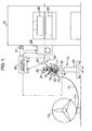
- Fig. 1 is a schematic view of an outline structure of a press stamping line in accordance with an embodiment of the present invention.
- Reference numeral 11 denotes a coil material.
- the coil material 11 is unwound by an uncoiler 12.
- Reference numeral 13 denotes a coil material feeding apparatus in accordance with an embodiment of the present invention.
- the coil material feeding apparatus 13 is provided with a coil material supplying portion 22 mentioned below, and position sensors 23 and 24 detecting a loop amount of the coil material 11, and these elements are mounted to a stand 25 in such a manner that heights thereof can be adjusted by a height adjusting apparatus 20.
- the coil material 11 passes through the coil material feeding apparatus 13 and forms a loop, the coil material 11 is fed to a mechanical press 27 via an intermittent feeding apparatus 28 so as to be subjected to a press stamping.
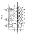
- the coil material feeding portion 22 includes a pair of feeding rollers 14 and 15 for transferring the coil material 11, a servo motor 16 for rotating the driven roller 14 in the feeding rollers 14 and 15, a driver 17 for driving the servo motor 16, a material correcting portion 19 in which a plurality of rollers 18 are arranged approximately in a line on each of upper and lower sides and the upper and lower roller lines arranged at alternately shifted positions in an advancing direction are placed on an upstream or downstream side of the feeding rollers 18, and an angle adjusting apparatus 21 capable of adjusting a feeding direction of the coil material 11.
- the upper and lower roller lines are structured such that the material fed toward the intermittent feeding apparatus 28 can pass through a gap between the upper and lower roller lines.
- the coil material 11 passes between the upper and lower roller lines, the coil material 11 is vertically deflected and expanded along an outer shape of the individual rollers 18, and winding is straightened.
- the upper and lower roller lines of the material correcting portion 19 are adjusted in a gap distance by a height adjusting mechanism constituted of two adjusting screws 42 and 43 for adjusting the gap distance, shown in Fig. 2, in correspondence to a quality, a thickness and the like of the material to be fed, whereby a straightening degree of the winding in the coil material is adjusted.
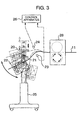
- the angle adjusting apparatus 21 of the coil material feeding portion 22 sets an angle of installation of the coil material feeding portion 22 in correspondence to a condition such as a thickness of the coil material and the like, within a range that a discharging direction of the coil material 11 from the coil material feeding portion 22 is, with respect to the advancing direction (approximately in a horizontal direction) of the coil material in the intermittent feeding apparatus 28, from a vertical direction to a horizontal direction being the same as the advancing direction of the coil material. (Refer to Fig. 3).
- a loop shape forms a quarter circular arc shown in Fig. 4 between the coil feeding portion and the intermittent feeding apparatus.
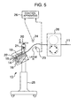
- the loop indicates an approximately half circle and the coil material is fed in a shape of a half circular arc.
- the angle of installation is set within the range including these directions.
- the driver 17 of the coil material feeding apparatus 13 and the position sensors 23 and 24 are connected to a control apparatus 26, and the control apparatus 26 is also used as a control apparatus for controlling the mechanical press 27 and the intermittent feeding apparatus 28.
- the intermittent feeding apparatus 28 is arranged at a position horizontally feeding the coil material 11 between a lower mold 29 and an upper mold 30 at a time of working on a side surface of the mechanical press 27.
- the mechanical press 27 is provided with a motor, a flywheel for storing a rotation force thereof, a crank shaft for converting the rotation force into a linear oscillating motion, a rotation angle detecting apparatus 31 for detecting an angle of rotation of the crank shaft, and the like, in the same manner as the conventional one.
- the uncoiler 12 defines a direction of the reel in such a manner that the coil material 11 is unwound from the lower side.
- the coil material feeding apparatus 13 is arranged at a position apart from the intermittent feeding apparatus 28 by adjusting a height of the stand 25 by means of the height adjusting apparatus 20 and adjusting a mounting angle of the coil material feeding portion 22 by means of the angle adjusting apparatus 21, respectively, in such a manner that a predetermined loop state can be obtained between the coil material feeding apparatus 13 and the intermittent feeding apparatus 28, with the coil material feeding portion 22 being positioned below and on the upstream side of the intermittent feeding apparatus 28.
- the lower position sensor 23 is arranged at a position for detecting a minimum loop length L1 of the coil material 11
- the upper position sensor 24 is arranged at a position for detecting a maximum loop length L2 of the coil material 11.
- the position sensors 23 and 24 are rotatably mounted to the stand 25 via respective levers, as shown in Fig. 6, and can adjust the position by swinging the levers.
- the position sensors 23 and 24 in the present embodiment employ a proximity switch, however, may employ the other type of position sensors.
- the loop state is monitored by the position sensors 23 and 24.
- the control apparatus 26 controls the driving of the servo motor 16 via the driver 17, adds an angle of rotation ⁇ to the angle of rotation of the feeding roller 14 on the drive side so as to increase the feeding amount of the coil material 11, and to set a proper loop length L3.
- the control apparatus 26 controls the driving of the servo motor 16 via the driver 17, subtracts the angle of rotation ⁇ from the angle of rotation of the feeding roller 14 so as to reduce the feeding amount of the coil material 11, and to set the proper loop length L3.
- the minimum loop length L1, the maximum loop length L2 and the proper loop length L3 are determined by a shape and a physical property of the coil material 11 to be used, a distance between the coil material feeding apparatus 13 and the intermittent feeding apparatus 28 and the like.
- the minimum and maximum loop lengths L1 and L2 are monitored by the position sensors 23 and 24, and the coil material 11 is fed to the intermittent feeding apparatus 28 while controlling the feeding amount of the feeding rollers 14 and 15 by the control apparatus 26, it is possible to carry out the high speed operation having a reduced bouncing and having a reduced load of the intermittent feeding apparatus 28.
- the driving motor 16 rotates the large-diameter roller 14 for feeding the material.
- a spur gear 44 is provided in the large-diameter feeding roller 14.
- a gear mechanism is structured such that a gear 45 for transmission engaging with the spur gear 44 is engaged with a small gear 46 provided in the small-diameter roller 18, and a rotation in the same direction of rotation is sequentially transmitted via a gear 47 for transmission. Accordingly, the feeding force of the material applied by the feeding roller 14 is not reduced by the leveler portion (the small-diameter roller lines) 19, and the material loop is formed in the same condition as that in the case that no leveler portion is provided, and can be fed to the intermittent feeding apparatus 28.
- the distance adjusting functions 41, 42 and 43 are independently provided between the rollers 14 and 15 and between the rollers 18, respectively, it is possible to adjust the holding, correcting and feeding of the material to the respective proper conditions in correspondence to the respective functions of the rollers.
- the angle of installation of the coil material feeding portion is set within the range from the vertical direction to the feeding direction of the coil material from the feeding portion to the same direction as the feeding direction, with respect to the advancing direction of the coil material in the intermittent feeding apparatus, there can be achieved the mechanism capable of adjusting the loop shape between one half circular arc and one quarter circular arc, it is easy to form the loop shape having the proper radius in correspondence to the material, and it is possible to supply the coil material at a further high speed.
- the coil material feeding apparatus doubles as the function of correcting the material
- the independently provided leveler is not required as well as it is possible to directly supply the material having a high quality with no material deflection to the intermittent feeding apparatus, so that the line length of an entire of the press line can be made short.
- the loop shape can be always monitored by two position sensors arranged above and below the loop and the rotation control apparatus of the drive roller, and it is possible to maintain the initially set optimum loop shape.
- the feeding roller doubles as the material lead-in pitch roller for correcting the material, it is possible to arrange the apparatus compact.
- the small roller lines rotate.
- the drive source can be commonly used by transmitting the driving of the large-diameter feeding roller through the gears, it is possible to intend to further save a space.
Landscapes
- Engineering & Computer Science (AREA)
- Mechanical Engineering (AREA)
- Winding, Rewinding, Material Storage Devices (AREA)
- Controlling Rewinding, Feeding, Winding, Or Abnormalities Of Webs (AREA)
- Straightening Metal Sheet-Like Bodies (AREA)
- Advancing Webs (AREA)
Abstract
Description
- The present invention relates to a coil material feeding apparatus for feeding coil material to an intermittent feeding apparatus of a mechanical press in a press stamping line.
- As shown in Fig. 7, in a conventional press stamping line, a
coil material 1 is fed from an uncoiler 2, via a leveler 3 for correcting material and a buffering section called as a looper for generating aloop 5, to anintermittent feeding apparatus 7 for feeding thecoil material 1 to a mechanical press 6. The leveler 3 is an apparatus for straightening the winding in the coil, and presses upper and lower rolls arranged alternately against each other, normally presses down the upper roll against the lower roll, thereby continuously stretching and compressing the material so as to flatten the coil. The leveler 3 is normally constituted of a pinch roll and a correcting roll. The pinch roll plays a part of pulling in the material, and the correcting roll plays a part of flattening the material. - In general, in the case of feeding the coil material to the feeding apparatus to the mechanical press, the feeding action is intermittently carried out in accordance with the pressing operation in which movement and stop are repeated. Vibration force generated at the start and stop times is applied to the coil material, whereby the coil material is vibrated and a ruffling phenomenon called as a bouncing is generated. When the bouncing mentioned above is generated, not only an excessive load is applied to the feeding apparatus, but also a deflection or a scratch is generated in the coil material. Accordingly, it is necessary to set the buffering section called as the looper.
- As a conventional method of reducing the bouncing in the coil material, there is a coil material feeding apparatus having a U-shaped looper provided with a U-shaped buffering section, an S-shaped looper provided with an S-shaped buffering section or the like. However, in accordance with the conventional U-shaped looper and the S-shaped looper, although the bouncing is reduced in comparison with the case provided with no buffering section, the bouncing is generated just all the same by a high speed operation. Accordingly, there is a problem that the operating speed can not be increased any more, and it is impossible to make full use of a press function in spite of a recent requirement of high speed press stamping. Further, since the looper itself has no drive source, the coil material is fed dependently on a pulling force of the intermittent feeding apparatus, and an extruding force of the leveler for flattening the coil material unwound by the uncoiler, so that there is a problem that the load is increased by just that much, thereby lowering the feeding capacity of the intermittent feeding apparatus and the leveler. Further, since it is necessary to set the buffering section long, there is a problem that the line length of the press line is increased.
- In order to solve the problems mentioned above, there has been proposed a coil material feeding apparatus which has a reduced bouncing in spite of a high speed operation, can lower the load of the intermittent feeding apparatus, and can shorten the line length of the press line. Refer, for example, to U.S. Patent No. 5392977.
- This apparatus is structured, as shown in Fig. 8, such that a pair of feeding rollers provided with a servo motor are arranged as a loop controller 4 near the
intermittent feeding apparatus 7 of the mechanical press 6, and the feeding rollers feed the material to theintermittent feeding apparatus 7 while forming aproper loop 5 in thecoil material 1. Further, a sensor for detecting a magnitude of theloop 5 in thecoil material 1 is provided. Thecoil material 1 is fed to theintermittent feeding apparatus 7 while maintaining a proper loop shape of theloop 5 by controlling a rotation of the servo motor on the basis of a signal of the sensor so as to control a feeding amount of thecoil material 1 fed by the feeding rollers. Accordingly, since it is possible to achieve a high speed operation while the bouncing in Fig. 7 is minimized, to improve the feeding capacity by reducing the load applied to theintermittent feeding apparatus 7, and to make the loop amount small, it is also possible to shorten the press line. - However, in accordance with a diversification of the kinds of press material in recent years, there is generated a necessity that the material feeding apparatus should correspond to various materials and feeding conditions.
- In general, a limit of radius of curvature of the material in the case of forming the loop is normally described as up to 500 times a thickness t of the material, and it is known that no deflection is generated in the material as far as the radius is more than the limit. This means that an allowable magnitude of the loop is different between a thin material and a thick material, and it is, of course, necessary to form a large loop in the thick material.
- In view of the material feeding apparatus described in the publication mentioned above on the basis of the matters mentioned above, the coil material feeding apparatus is placed below the
intermittent feeding apparatus 7 in connection with the matter that thematerial 1 is fed upward from the lower side. In the case of forming thelarge loop 5, in order to form a large radius R, it is necessary to arrange the loop controller 4 considerably below theintermittent feeding apparatus 7. However, on a downstream side of the feeding apparatus, thematerial 1 from the uncoiler 2 also forms a loop in a lower side, and a large radius R is required here. Accordingly, the apparatus is drastically restricted in a vertical direction, and there is a risk that a suitable loop can not be formed. - In the same manner, an approximately quarter
circular arc loop 5 is formed from the loop controller 4 to theintermittent feeding apparatus 7. With respect to the quarter circular arc portion, the loop controller 4 can be arranged near theintermittent feeding apparatus 7 because a loop 5' of the thin material can be formed with a small radius R, however, it is necessary that theloop controller 7 is arranged apart from theintermittent feeding apparatus 7 in comparison with the case of the thin material in order to form a proper loop because aloop 5" of the thick material requires a large radius, as shown in Fig. 9. As a result, the press line tends to be significantly long in the case of the thick material, in comparison with the thin material. - Further, on the assumption that the conventional system mentioned above has a section in which the material becomes free during a period that the
coil material 1 flows from the uncoiler 2 toward theintermittent feeding apparatus 7, a slight bouncing of the material in the section deteriorates a quality of the material. In the apparatus of the publication mentioned above as indicated in Fig. 8, since the material hangs from an upstream portion of the loop controller 4, there is a risk that thematerial 1 in which the deflection is corrected by the leveler 3 is left as it is for a long time before starting the feeding operation, whereby the deflection is again generated, and the material generates a slight bouncing at a time of starting or stopping the feeding, whereby the scratch is generated. - Taking the problems mentioned above into consideration, the present invention provides a coil material feeding apparatus which can feed a material flexibly and with a high quality. In other words, the present invention provides a coil material feeding apparatus provided with a leveler (a material correcting function) in which a setting angle can be adjusted.
- In order to achieve the object mentioned above, in accordance with the present invention, there is provided a coil material feeding apparatus for feeding a coil material to an intermittent feeding apparatus of a mechanical press, comprising:
- a coil material feeding portion;
- a position sensor provided on a downstream side of the coil material feeding portion and detecting a loop amount of a coil material;
- a control apparatus controlling a servo motor on the basis of a signal output from the position sensor so as to control a feeding amount of the coil material by feeding rollers; and
- a stand holding the coil material feeding portion in a state in which a mounting angle of the coil material feeding portion is adjustable in such a manner as to change a feeding angle of the material in correspondence to a condition.
- The coil material feeding portion is arranged on an upstream side of a material inlet in the intermittent feeding apparatus and includes a pair of feeding rollers feeding the material to the intermittent feeding apparatus while forming a proper loop in the material, a servo motor driving said feeding rollers, a material correcting portion structured such that roller lines having a plurality of rollers respectively arranged on upper and lower sides approximately in a line and at alternately shifted positions in an advancing direction allow the material fed to the intermittent feeding apparatus to pass through a gap between the upper and lower roller lines, and placed on an upstream side or a downstream side of said feeding rollers, and a height adjusting mechanism adjusting a distance of the gap between the upper and lower roller lines in the material correcting portion in correspondence to quality, thickness and the like of the material to be fed, and capable of adjusting a removing degree of winding in the coil material by adjusting the gap distance between the upper and lower roller lines.
- In accordance with the coil material feeding apparatus of the present invention, the coil material feeding portion including the feeding rollers driven by the servo motor is arranged near the intermittent feeding apparatus of the mechanical press, and the proper loop is formed and the material is fed while the coil material is fed by the feeding rollers. Further, since the coil material is fed to the intermittent feeding apparatus while maintaining the proper loop shape, by controlling the rotation of the servo motor so as to control the feeding amount of the coil material fed by the feeding rollers, on the basis of the signal output from the position sensor detecting the magnitude of the loop in the coil material, it is possible to achieve a high speed operation with a reduced bouncing and a reduced load applied to the intermittent feeding apparatus.
- Further, the coil material feeding portion of the feeding rollers is provided with the lines in which a plurality of rollers are linearly arranged, on the upper and lower sides respectively, and has a material correcting function achieved by passing the material between the upper and lower roller lines so as to straighten the winding in the material and to remove an internal stress of the material. Further, it is set such that the respective rollers in the upper and lower lines are arranged at the alternately shifted positions with respect to the advancing direction of the coil material, whereby the winding in the coil material is straightened during a period that the coil material passing between the upper and lower rollers is vertically deflected and expanded along an outer shape of each of the rollers. The coil material feeding portion is arranged near the intermittent feeding apparatus, and, an angle of installation of the coil material feeding portion is set such that the coil material is fed at an angle within a range that a feeding direction of the coil material from the coil material feeding portion is, with respect to the advancing direction of the coil material in the intermittent feeding apparatus, from a vertical direction to the same direction as the advancing direction. Accordingly, the coil material feeding portion is provided with a function capable of adjusting the angle.
- In accordance with the coil material feeding apparatus of the present invention, the material to be fed is in an improved quality state in which the deflection is corrected just before being fed, and can sufficiently correspond to a press stamping in which a high precision is required. Further, with respect to the loop formation, since the angle of installation of the coil material feeding portion can be adjusted, a little more gentle loop can be formed in place of the conventional quarter circular arc. Accordingly, it is necessary to change the angle of installation in correspondence to the thickness of the material so as to adjust the loop radius R, however, it is possible to easily increase the loop radius R by setting the angle of installation close to the advancing direction of the coil material in the intermittent feeding apparatus even in the case of the thick material. Even in this case, since the loop radius can be changed only by adjusting the angle without moving the position of the feeding apparatus as the conventional apparatus, it is not necessary to lengthen the press line.
- Further, since the leveler function is added to the coil material feeding apparatus in accordance with the present invention, the independently placed leveler apparatus which has been conventionally required is not necessary, and it is possible to intend to shorten the press line from the leveler to the feeding apparatus. At the same time, it is possible to do away with the scratch and the deflection generated due to the bouncing or the like between the leveler and the feeding apparatus.
- Further, the roller lines may be constituted of the feeding rollers mentioned above serving as a pair of upper and lower large-diameter rollers for powerfully extruding the material by a high torque, and a plurality of small-diameter roller lines repeating a small deflection and expansion for correcting the material.
- Further, the large-diameter feeding rollers and the small-diameter roller lines may be independently provided with respective distance adjusting mechanisms between the rollers, and the adjusting method may be of a mechanical type or an air type.
- Further, the rotation driving for the large-diameter feeding rollers may be transmitted to the small-diameter roller lines, whereby it is possible to obtain a rotation of the small-diameter roller lines.
- Accordingly, the feeding power generated by the feeding rollers can transmit the material without being weakened by the small-diameter roller lines.
-
- Fig. 1 is a schematic view of an outline structure of a press stamping line in accordance with an embodiment of the present invention;
- Fig. 2 is a partly enlarged view of feeding rollers and roller lines in a coil material feeding portion in accordance with the present embodiment;
- Fig. 3 is a view indicating an operating state in correspondence to a difference in thickness of a coil material in accordance with the present embodiment;
- Fig. 4 is a schematic view of an operation in the case of working a thin material of the coil material, in accordance with the present embodiment;
- Fig. 5 is a schematic view of an operation in the case of working a thick material of the coil material, in accordance with the present embodiment;
- Fig. 6 is a partly enlarged view explaining a motion of the coil material in accordance with the present embodiment;
- Fig. 7 is a schematic view of an outline structure of a conventional press stamping line;
- Fig. 8 is a schematic view of an outline structure of another conventional press stamping line; and
- Fig. 9 is a view explaining an operation in correspondence to a difference in thickness of the coil material in accordance with the conventional coil material feeding apparatus shown in Fig. 8.
- Fig. 1 is a schematic view of an outline structure of a press stamping line in accordance with an embodiment of the present invention.
Reference numeral 11 denotes a coil material. Thecoil material 11 is unwound by anuncoiler 12.Reference numeral 13 denotes a coil material feeding apparatus in accordance with an embodiment of the present invention. The coilmaterial feeding apparatus 13 is provided with a coilmaterial supplying portion 22 mentioned below, andposition sensors coil material 11, and these elements are mounted to astand 25 in such a manner that heights thereof can be adjusted by aheight adjusting apparatus 20. After thecoil material 11 passes through the coilmaterial feeding apparatus 13 and forms a loop, thecoil material 11 is fed to a mechanical press 27 via anintermittent feeding apparatus 28 so as to be subjected to a press stamping. - In the coil
material feeding apparatus 13, the coilmaterial feeding portion 22 includes a pair of feedingrollers coil material 11, aservo motor 16 for rotating the drivenroller 14 in the feedingrollers driver 17 for driving theservo motor 16, amaterial correcting portion 19 in which a plurality ofrollers 18 are arranged approximately in a line on each of upper and lower sides and the upper and lower roller lines arranged at alternately shifted positions in an advancing direction are placed on an upstream or downstream side of the feedingrollers 18, and anangle adjusting apparatus 21 capable of adjusting a feeding direction of thecoil material 11. - In the
material correcting portion 19, the upper and lower roller lines are structured such that the material fed toward theintermittent feeding apparatus 28 can pass through a gap between the upper and lower roller lines. When thecoil material 11 passes between the upper and lower roller lines, thecoil material 11 is vertically deflected and expanded along an outer shape of theindividual rollers 18, and winding is straightened. The upper and lower roller lines of thematerial correcting portion 19 are adjusted in a gap distance by a height adjusting mechanism constituted of two adjustingscrews - The
angle adjusting apparatus 21 of the coilmaterial feeding portion 22 sets an angle of installation of the coilmaterial feeding portion 22 in correspondence to a condition such as a thickness of the coil material and the like, within a range that a discharging direction of thecoil material 11 from the coilmaterial feeding portion 22 is, with respect to the advancing direction (approximately in a horizontal direction) of the coil material in theintermittent feeding apparatus 28, from a vertical direction to a horizontal direction being the same as the advancing direction of the coil material. (Refer to Fig. 3). - In other words, when setting the discharging direction of the coil material from the coil feeding portion to a state close to the vertical direction to the advancing direction of the intermittent feeding apparatus, a loop shape forms a quarter circular arc shown in Fig. 4 between the coil feeding portion and the intermittent feeding apparatus. Further, in the case of discharging the coil material in a state close to the horizontal direction shown in Fig. 5, the loop indicates an approximately half circle and the coil material is fed in a shape of a half circular arc. In accordance with the present invention, the angle of installation is set within the range including these directions.
- The
driver 17 of the coilmaterial feeding apparatus 13 and theposition sensors control apparatus 26, and thecontrol apparatus 26 is also used as a control apparatus for controlling the mechanical press 27 and theintermittent feeding apparatus 28. Theintermittent feeding apparatus 28 is arranged at a position horizontally feeding thecoil material 11 between alower mold 29 and anupper mold 30 at a time of working on a side surface of the mechanical press 27. - The mechanical press 27 is provided with a motor, a flywheel for storing a rotation force thereof, a crank shaft for converting the rotation force into a linear oscillating motion, a rotation
angle detecting apparatus 31 for detecting an angle of rotation of the crank shaft, and the like, in the same manner as the conventional one. - Next, a description will be given of an operation of the embodiment mentioned above. As shown in Fig. 1, the
uncoiler 12 defines a direction of the reel in such a manner that thecoil material 11 is unwound from the lower side. The coilmaterial feeding apparatus 13 is arranged at a position apart from theintermittent feeding apparatus 28 by adjusting a height of thestand 25 by means of theheight adjusting apparatus 20 and adjusting a mounting angle of the coilmaterial feeding portion 22 by means of theangle adjusting apparatus 21, respectively, in such a manner that a predetermined loop state can be obtained between the coilmaterial feeding apparatus 13 and theintermittent feeding apparatus 28, with the coilmaterial feeding portion 22 being positioned below and on the upstream side of theintermittent feeding apparatus 28. Further, thelower position sensor 23 is arranged at a position for detecting a minimum loop length L1 of thecoil material 11, and theupper position sensor 24 is arranged at a position for detecting a maximum loop length L2 of thecoil material 11. Theposition sensors stand 25 via respective levers, as shown in Fig. 6, and can adjust the position by swinging the levers. Theposition sensors - In order to keep a condition that the loop state of the
coil material 11 between theintermittent feeding apparatus 28 and the coilmaterial feeding apparatus 13 exists between the minimum loop length L1 and the maximum loop length L2, and a difference between the lengths L2 and L1 is equal to or larger than the feeding pitch of the mechanical press 27, the loop state is monitored by theposition sensors coil material 11 becomes small and the minimum loop length L1 is detected by theposition sensor 23, the signal is transmitted to thecontrol apparatus 26, thecontrol apparatus 26 controls the driving of theservo motor 16 via thedriver 17, adds an angle of rotation α to the angle of rotation of the feedingroller 14 on the drive side so as to increase the feeding amount of thecoil material 11, and to set a proper loop length L3. On the contrary, when the loop becomes large and the maximum loop length L2 is detected by theposition sensor 24, the signal is transmitted to thecontrol apparatus 26, thecontrol apparatus 26 controls the driving of theservo motor 16 via thedriver 17, subtracts the angle of rotation α from the angle of rotation of the feedingroller 14 so as to reduce the feeding amount of thecoil material 11, and to set the proper loop length L3. The minimum loop length L1, the maximum loop length L2 and the proper loop length L3 are determined by a shape and a physical property of thecoil material 11 to be used, a distance between the coilmaterial feeding apparatus 13 and theintermittent feeding apparatus 28 and the like. - As mentioned above, in accordance with the embodiment mentioned above, since the minimum and maximum loop lengths L1 and L2 are monitored by the
position sensors coil material 11 is fed to theintermittent feeding apparatus 28 while controlling the feeding amount of the feedingrollers control apparatus 26, it is possible to carry out the high speed operation having a reduced bouncing and having a reduced load of theintermittent feeding apparatus 28. - In this case, the operation and motion for monitoring the minimum and maximum loop lengths and controlling the feeding amount of the feeding roller to an optimum level in the above publication can be incorporated with reference into the present invention.
- In the embodiment, as shown in Fig. 2, the driving
motor 16 rotates the large-diameter roller 14 for feeding the material. Aspur gear 44 is provided in the large-diameter feeding roller 14. Further, a gear mechanism is structured such that agear 45 for transmission engaging with thespur gear 44 is engaged with asmall gear 46 provided in the small-diameter roller 18, and a rotation in the same direction of rotation is sequentially transmitted via agear 47 for transmission. Accordingly, the feeding force of the material applied by the feedingroller 14 is not reduced by the leveler portion (the small-diameter roller lines) 19, and the material loop is formed in the same condition as that in the case that no leveler portion is provided, and can be fed to theintermittent feeding apparatus 28. - Further, since the distance adjusting functions 41, 42 and 43 are independently provided between the
rollers rollers 18, respectively, it is possible to adjust the holding, correcting and feeding of the material to the respective proper conditions in correspondence to the respective functions of the rollers. - Since the angle of installation of the coil material feeding portion is set within the range from the vertical direction to the feeding direction of the coil material from the feeding portion to the same direction as the feeding direction, with respect to the advancing direction of the coil material in the intermittent feeding apparatus, there can be achieved the mechanism capable of adjusting the loop shape between one half circular arc and one quarter circular arc, it is easy to form the loop shape having the proper radius in correspondence to the material, and it is possible to supply the coil material at a further high speed.
- Further, since the coil material feeding apparatus doubles as the function of correcting the material, the independently provided leveler is not required as well as it is possible to directly supply the material having a high quality with no material deflection to the intermittent feeding apparatus, so that the line length of an entire of the press line can be made short.
- Further, the loop shape can be always monitored by two position sensors arranged above and below the loop and the rotation control apparatus of the drive roller, and it is possible to maintain the initially set optimum loop shape.
- In this case, in order to feed the material from the uncoiler to the intermittent feeding apparatus at a high speed, a great torque is required in the feeding rollers. In the case the feeding drive (the material feeding) is obtained only by the small-diameter rollers, a significantly large-sized drive motor is required for the purpose of rotating the small-diameter rollers at a high speed under a state in which a friction force is applied to the small-diameter rollers. However, in accordance with this structure, since the exclusive feeding rollers for forming the loop and feeding the material are independently provided, the feeding function as the material feeding apparatus is high.
- Further, since the feeding roller doubles as the material lead-in pitch roller for correcting the material, it is possible to arrange the apparatus compact.
- Further, in the case of passing the material through the leveler portion of the small-diameter roller lines, it is desirable that the small roller lines rotate. However, since the drive source can be commonly used by transmitting the driving of the large-diameter feeding roller through the gears, it is possible to intend to further save a space.
Claims (5)
- A coil material feeding apparatus for feeding a coil material to an intermittent feeding apparatus of a mechanical press, comprising:a coil material feeding portion including a pair of feeding rollers arranged on an upstream side of a material inlet in the intermittent feeding apparatus and feeding the material to the intermittent feeding apparatus while forming a proper loop in the material and a servo motor driving said feeding rollers;a position sensor provided on a downstream side of said coil material feeding portion and detecting a loop amount of said coil material;a control apparatus controlling said servo motor on the basis of a signal output from said position sensor so as to control a feeding amount of the coil material by said feeding rollers; anda stand holding said coil material feeding portion in a state in which a mounting angle of the coil material feeding portion is adjustable in such a manner as to change a feeding angle of the material in correspondence to a condition.
- A coil material feeding apparatus according to claim 1, wherein the coil material feeding portion comprises a material correcting portion structured such that upper and lower roller lines having a plurality of rollers respectively arranged approximately in a line and at alternately shifted positions in an advancing direction allow the coil material fed toward the intermittent feeding apparatus to pass through a gap between the upper and lower roller lines, and placed on an upstream side or a downstream side of said feeding rollers, and a height adjusting mechanism adjusting the distance of the gap between the upper and lower roller lines in said material correcting portion.
- A coil material feeding apparatus as claimed in claim 2, wherein said roller line is constituted of said feeding rollers serving as a pair of large-diameter rollers for powerfully extruding the material by a high torque, and a plurality of small-diameter roller lines repeating a small deflection and expansion for correcting the material.
- A coil material feeding apparatus as claimed in claim 3, wherein said large-diameter feeding rollers and said small-diameter roller line are independently provided with respective distance adjusting mechanisms.
- A coil material feeding apparatus as claimed in claim 3 or 4, wherein the rotation driving for said large-diameter feeding roller is transmitted to the small-diameter roller line, whereby a rotation of the small-diameter roller line is obtained.
Applications Claiming Priority (2)
| Application Number | Priority Date | Filing Date | Title |
|---|---|---|---|
| JP2002309193A JP3964303B2 (en) | 2002-10-24 | 2002-10-24 | Coil material supply device |
| JP2002309193 | 2002-10-24 |
Publications (3)
| Publication Number | Publication Date |
|---|---|
| EP1413371A2 true EP1413371A2 (en) | 2004-04-28 |
| EP1413371A3 EP1413371A3 (en) | 2004-09-22 |
| EP1413371B1 EP1413371B1 (en) | 2005-12-07 |
Family
ID=32064350
Family Applications (1)
| Application Number | Title | Priority Date | Filing Date |
|---|---|---|---|
| EP03256578A Expired - Lifetime EP1413371B1 (en) | 2002-10-24 | 2003-10-17 | Coil material feeding apparatus |
Country Status (7)
| Country | Link |
|---|---|
| US (1) | US20040079780A1 (en) |
| EP (1) | EP1413371B1 (en) |
| JP (1) | JP3964303B2 (en) |
| KR (1) | KR100583685B1 (en) |
| CN (1) | CN1289373C (en) |
| DE (1) | DE60302633T2 (en) |
| TW (1) | TWI229652B (en) |
Cited By (6)
| Publication number | Priority date | Publication date | Assignee | Title |
|---|---|---|---|---|
| WO2007147721A1 (en) * | 2006-06-19 | 2007-12-27 | Siemens Aktiengesellschaft | Unwinding device |
| EP1916042A1 (en) * | 2006-10-23 | 2008-04-30 | Fecker GmbH Maschinenbau | Line for straightening strip material wrapped to a coil and for feeding in the same to a processing machine |
| CN103381451A (en) * | 2013-07-11 | 2013-11-06 | 德清振达电气有限公司 | Feeding device of automatic stock cutter |
| CN113264401A (en) * | 2021-05-31 | 2021-08-17 | 韦俊 | Cloth extension device of gauze mask production machine |
| CN114955638A (en) * | 2022-06-06 | 2022-08-30 | 福州市长乐区华大纺织有限公司 | A receive material tensioning adjustment device for weaving cloth production |
| WO2023217601A1 (en) * | 2022-05-13 | 2023-11-16 | TRUMPF Werkzeugmaschinen SE + Co. KG | Method and mechanical arrangement for processing a plastically deformable workpiece, more particularly a plastically deformable sheet |
Families Citing this family (38)
| Publication number | Priority date | Publication date | Assignee | Title |
|---|---|---|---|---|
| KR100854655B1 (en) * | 2007-02-22 | 2008-08-27 | 박영원 | Material supply device for press work |
| JP5132197B2 (en) | 2007-06-06 | 2013-01-30 | 株式会社デンソー | Plastic working method and plastic working system |
| JP5139034B2 (en) | 2007-10-31 | 2013-02-06 | 株式会社三共製作所 | Material feeder |
| CN101439467B (en) * | 2007-11-23 | 2012-09-12 | 丁晓跃 | Metal bar section roll milling and processing equipment, and network control system thereof |
| KR200445975Y1 (en) * | 2008-05-13 | 2009-09-14 | 김수동 | Feeding interval adjusting device of multi forming machine |
| DE102008061356B4 (en) * | 2008-12-10 | 2014-08-07 | Manfred Wanzke | Tape threading system and method for inserting a strip |
| JP2011104650A (en) * | 2009-11-17 | 2011-06-02 | Matsumoto Seisakusho:Kk | Coil material supply device for thin plate of high-speed press |
| US9073721B2 (en) * | 2010-09-01 | 2015-07-07 | Global Feeding systems, Inc. | System for high speed feeding a thin sheet metal strip into a reciprocating press |
| KR101281241B1 (en) | 2011-11-02 | 2013-07-05 | 주식회사 포스코 | Apparatus for supplying band |
| US9352913B2 (en) * | 2013-03-14 | 2016-05-31 | Sealy Technology, Llc | Innerspring manufacturing and assembly system and components for selectable coil orientation, position adjustment and coil conveyance |
| CN103241593B (en) * | 2013-05-15 | 2016-04-06 | 中国神华能源股份有限公司 | For the method and system of control cables reel |
| CN103418703B (en) * | 2013-07-24 | 2015-07-29 | 海宁市智慧光电有限公司 | Material guide structure on a kind of LED lamp holder former |
| CN103522322B (en) * | 2013-10-21 | 2015-05-06 | 浙江飞力科技股份有限公司 | Cutting machine of plastic tape for sofa rack packaging |
| CN104056898A (en) * | 2014-05-26 | 2014-09-24 | 太仓兴锋脚轮有限公司 | Caster drive plate punch forming equipment |
| US11076705B2 (en) | 2014-05-30 | 2021-08-03 | Sealy Technology, Llc | Spring core with integrated cushioning layer |
| JP6691362B2 (en) * | 2015-08-28 | 2020-04-28 | コマツ産機株式会社 | Coil material conveying device, press system, and coil material conveying method |
| ES2977948T3 (en) | 2015-12-17 | 2024-09-03 | Sealy Technology Llc | Coiled helical spring with variable load response and mattresses that include the same |
| EP3841921B1 (en) | 2016-01-21 | 2024-12-25 | Sealy Technology, LLC | Coil-in-coil springs with non-linear loading responses and mattresses including the same |
| JP6693769B2 (en) * | 2016-03-01 | 2020-05-13 | コマツ産機株式会社 | Roll feeder and coil material conveying method |
| CN105880402A (en) * | 2016-05-10 | 2016-08-24 | 新乡市盛达电源科技有限公司 | Battery case stamping steel belt guiding rack |
| US10598242B2 (en) | 2016-05-20 | 2020-03-24 | Sealy Technology, Llc | Coil springs with non-linear loading responses and mattresses including the same |
| CN107381172A (en) * | 2017-08-11 | 2017-11-24 | 中北大学 | Work-feeding means for ultrasonic consolidation increasing material manufacturing machine |
| KR102822256B1 (en) | 2017-10-31 | 2025-06-17 | 실리 테크놀로지 엘엘씨 | Pocket coil spring assembly including flexible foam |
| CN107838320A (en) * | 2017-11-22 | 2018-03-27 | 烟台亿拉得包装科技股份有限公司 | Easy-open bottle lid punching feeding buffer unit and its way to play for time |
| KR102043754B1 (en) * | 2018-04-25 | 2019-11-12 | (주)세원물산 | Molding apparatus with anti-bending function for a coil |
| CN109848317B (en) * | 2018-12-27 | 2020-08-25 | 上海精星仓储设备工程有限公司 | Material arc machine for continuous punching and rolling equipment |
| JP7529576B2 (en) | 2019-02-04 | 2024-08-06 | 株式会社三共製作所 | Plate material supply device |
| DE102019206556A1 (en) * | 2019-05-07 | 2020-11-12 | Wafios Aktiengesellschaft | Method and device for feeding an elongated workpiece to a forming machine |
| US11364533B2 (en) * | 2020-03-28 | 2022-06-21 | Sewon Precision Industry Co., Ltd. | Transfer pressing apparatus and method |
| CN111457826B (en) * | 2020-03-31 | 2021-10-22 | 鞍钢股份有限公司 | A method for quick calibration of the angle of a straightening machine |
| TWI886317B (en) | 2020-09-30 | 2025-06-11 | 日商三共製作所股份有限公司 | Processing production line system |
| EP4255650A4 (en) * | 2020-12-01 | 2025-01-15 | Magna International Inc | CORRUGATED ROLLING DIE ASSEMBLY |
| JP7609645B2 (en) * | 2021-01-22 | 2025-01-07 | 株式会社アマダ | Press system and method for controlling press system |
| JP7733532B2 (en) * | 2021-10-11 | 2025-09-03 | 株式会社アマダ | Coil material straightening device and coil material conveying method |
| KR102484785B1 (en) * | 2022-03-18 | 2023-01-05 | 주식회사 엔도로보틱스 | Apparatus for moving a member |
| CN115069944B (en) * | 2022-06-27 | 2023-03-14 | 南京航空航天大学 | Feeding device of six-axis bending machine and using method |
| CN115676263A (en) * | 2022-12-21 | 2023-02-03 | 良启金属南通有限公司 | Feeding device capable of intermittently feeding |
| CN116534640A (en) * | 2023-04-10 | 2023-08-04 | 安徽天富环保科技材料有限公司 | Activated carbon fiber surface non-destructive cleaning device |
Family Cites Families (10)
| Publication number | Priority date | Publication date | Assignee | Title |
|---|---|---|---|---|
| US2087010A (en) * | 1934-06-26 | 1937-07-13 | Mckay Machine Co | Method and apparatus for preventing coil breaks in sheet metal |
| US3459027A (en) * | 1967-09-28 | 1969-08-05 | Raymond G Brownstein | Method for levelling sheet stock |
| US4608844A (en) * | 1981-11-23 | 1986-09-02 | Sesco, Inc. | Cradle straightener feeder |
| JPS59141314A (en) * | 1983-01-31 | 1984-08-14 | Matsushita Electric Works Ltd | Feeding system of beltlike material for press or roll work or the like |
| US4953808A (en) * | 1988-08-08 | 1990-09-04 | Perfecto Industries, Inc. | Apparatus for supplying a sheet metal strip to a press |
| US5392977A (en) * | 1993-11-09 | 1995-02-28 | Sankyo Seisakusho Co. | Coil material supply apparatus for an intermittent feed device |
| US5377517A (en) * | 1993-11-09 | 1995-01-03 | Sankyo Seisakusho Co. | Reforming apparatus |
| US5413304A (en) * | 1993-11-09 | 1995-05-09 | Sankyo Seisakusho Co. | Apparatus for supporting coil material supply device |
| DE19648896A1 (en) * | 1996-01-19 | 1997-07-24 | Minster Machine Co | Die transfer control system with damped successor |
| US20040050131A1 (en) * | 2002-09-17 | 2004-03-18 | Militaru Cristian I. | Straightening roller assembly for section reducing a steel tube to achieve excess fiber length of an elongate bundle of optical fibers contained within the tube |
-
2002
- 2002-10-24 JP JP2002309193A patent/JP3964303B2/en not_active Expired - Lifetime
-
2003
- 2003-09-30 TW TW092126987A patent/TWI229652B/en not_active IP Right Cessation
- 2003-10-10 US US10/683,252 patent/US20040079780A1/en not_active Abandoned
- 2003-10-17 DE DE60302633T patent/DE60302633T2/en not_active Expired - Lifetime
- 2003-10-17 EP EP03256578A patent/EP1413371B1/en not_active Expired - Lifetime
- 2003-10-23 KR KR1020030074250A patent/KR100583685B1/en not_active Expired - Lifetime
- 2003-10-24 CN CNB2003101029193A patent/CN1289373C/en not_active Expired - Lifetime
Cited By (8)
| Publication number | Priority date | Publication date | Assignee | Title |
|---|---|---|---|---|
| WO2007147721A1 (en) * | 2006-06-19 | 2007-12-27 | Siemens Aktiengesellschaft | Unwinding device |
| US8136215B2 (en) | 2006-06-19 | 2012-03-20 | Siemens Aktiengesellschaft | Uncoiling device |
| EP1916042A1 (en) * | 2006-10-23 | 2008-04-30 | Fecker GmbH Maschinenbau | Line for straightening strip material wrapped to a coil and for feeding in the same to a processing machine |
| CN103381451A (en) * | 2013-07-11 | 2013-11-06 | 德清振达电气有限公司 | Feeding device of automatic stock cutter |
| CN113264401A (en) * | 2021-05-31 | 2021-08-17 | 韦俊 | Cloth extension device of gauze mask production machine |
| CN113264401B (en) * | 2021-05-31 | 2022-08-23 | 韦俊 | Cloth extension device of gauze mask production machine |
| WO2023217601A1 (en) * | 2022-05-13 | 2023-11-16 | TRUMPF Werkzeugmaschinen SE + Co. KG | Method and mechanical arrangement for processing a plastically deformable workpiece, more particularly a plastically deformable sheet |
| CN114955638A (en) * | 2022-06-06 | 2022-08-30 | 福州市长乐区华大纺织有限公司 | A receive material tensioning adjustment device for weaving cloth production |
Also Published As
| Publication number | Publication date |
|---|---|
| KR100583685B1 (en) | 2006-05-25 |
| JP2004142876A (en) | 2004-05-20 |
| US20040079780A1 (en) | 2004-04-29 |
| KR20040036620A (en) | 2004-04-30 |
| EP1413371A3 (en) | 2004-09-22 |
| DE60302633T2 (en) | 2006-08-10 |
| JP3964303B2 (en) | 2007-08-22 |
| CN1498704A (en) | 2004-05-26 |
| TWI229652B (en) | 2005-03-21 |
| DE60302633D1 (en) | 2006-01-12 |
| EP1413371B1 (en) | 2005-12-07 |
| CN1289373C (en) | 2006-12-13 |
| TW200418706A (en) | 2004-10-01 |
Similar Documents
| Publication | Publication Date | Title |
|---|---|---|
| EP1413371B1 (en) | Coil material feeding apparatus | |
| EP2058059B1 (en) | Methods and apparatus to drive material conditioning machines | |
| EP0239364A2 (en) | A drive system for a bending machine | |
| CN1137066A (en) | Tension control device for production line | |
| CN220148776U (en) | Following roller mechanism in film winding equipment | |
| US6116068A (en) | Method of regulating the drive of a drawing machine, and drawing device | |
| EP3922374B1 (en) | Plate material supplying apparatus | |
| US20040221635A1 (en) | Method for producing strip-shaped input stock, especially from metal, which is profiled in subsequent sections, and corresponding device | |
| WO2018220858A1 (en) | Roll feeder | |
| ITMI972197A1 (en) | MULTI-STEP DRAWING MACHINE EQUIPPED WITH A DEVICE FOR REGULATION AND CONTROL OF THE TENSION OF THE WIRE IN PARTICULAR PROCESSING | |
| CN213863929U (en) | Automatic tensioning device of belt conveyor | |
| US7334446B1 (en) | Method for producing a striplike pre-material made of metal, especially a pre-material which has been profiled into regularly reoccurring sections, and device therefor | |
| US5413304A (en) | Apparatus for supporting coil material supply device | |
| US12036593B2 (en) | Flexibly rolling metal strip material | |
| KR200339022Y1 (en) | Steel plate leveler | |
| JPH0390214A (en) | Leveler feed | |
| CN114453439A (en) | Strip steel threading deviation correcting method and equipment | |
| KR102131335B1 (en) | Notching system for improving machining precision | |
| JP5717117B2 (en) | Strip material feeder | |
| KR20020080319A (en) | A wire rod working system | |
| JP3830383B2 (en) | Intermittent feeder | |
| JP7733532B2 (en) | Coil material straightening device and coil material conveying method | |
| JPS60234727A (en) | Device for feeding coil material | |
| CN220563932U (en) | Automatic deviation correcting and conveying device of offset press | |
| JP4162331B2 (en) | Slab forming method and apparatus |
Legal Events
| Date | Code | Title | Description |
|---|---|---|---|
| PUAI | Public reference made under article 153(3) epc to a published international application that has entered the european phase |
Free format text: ORIGINAL CODE: 0009012 |
|
| 17P | Request for examination filed |
Effective date: 20031030 |
|
| AK | Designated contracting states |
Kind code of ref document: A2 Designated state(s): AT BE BG CH CY CZ DE DK EE ES FI FR GB GR HU IE IT LI LU MC NL PT RO SE SI SK TR |
|
| AX | Request for extension of the european patent |
Extension state: AL LT LV MK |
|
| PUAL | Search report despatched |
Free format text: ORIGINAL CODE: 0009013 |
|
| AK | Designated contracting states |
Kind code of ref document: A3 Designated state(s): AT BE BG CH CY CZ DE DK EE ES FI FR GB GR HU IE IT LI LU MC NL PT RO SE SI SK TR |
|
| AX | Request for extension of the european patent |
Extension state: AL LT LV MK |
|
| GRAP | Despatch of communication of intention to grant a patent |
Free format text: ORIGINAL CODE: EPIDOSNIGR1 |
|
| AKX | Designation fees paid |
Designated state(s): DE FR GB IT |
|
| GRAS | Grant fee paid |
Free format text: ORIGINAL CODE: EPIDOSNIGR3 |
|
| GRAA | (expected) grant |
Free format text: ORIGINAL CODE: 0009210 |
|
| AK | Designated contracting states |
Kind code of ref document: B1 Designated state(s): DE FR GB IT |
|
| PG25 | Lapsed in a contracting state [announced via postgrant information from national office to epo] |
Ref country code: IT Free format text: LAPSE BECAUSE OF FAILURE TO SUBMIT A TRANSLATION OF THE DESCRIPTION OR TO PAY THE FEE WITHIN THE PRESCRIBED TIME-LIMIT;WARNING: LAPSES OF ITALIAN PATENTS WITH EFFECTIVE DATE BEFORE 2007 MAY HAVE OCCURRED AT ANY TIME BEFORE 2007. THE CORRECT EFFECTIVE DATE MAY BE DIFFERENT FROM THE ONE RECORDED. Effective date: 20051207 |
|
| REG | Reference to a national code |
Ref country code: GB Ref legal event code: FG4D |
|
| REF | Corresponds to: |
Ref document number: 60302633 Country of ref document: DE Date of ref document: 20060112 Kind code of ref document: P |
|
| ET | Fr: translation filed | ||
| PLBE | No opposition filed within time limit |
Free format text: ORIGINAL CODE: 0009261 |
|
| STAA | Information on the status of an ep patent application or granted ep patent |
Free format text: STATUS: NO OPPOSITION FILED WITHIN TIME LIMIT |
|
| 26N | No opposition filed |
Effective date: 20060908 |
|
| REG | Reference to a national code |
Ref country code: FR Ref legal event code: PLFP Year of fee payment: 13 |
|
| REG | Reference to a national code |
Ref country code: FR Ref legal event code: PLFP Year of fee payment: 14 |
|
| REG | Reference to a national code |
Ref country code: FR Ref legal event code: PLFP Year of fee payment: 15 |
|
| REG | Reference to a national code |
Ref country code: FR Ref legal event code: PLFP Year of fee payment: 16 |
|
| PGFP | Annual fee paid to national office [announced via postgrant information from national office to epo] |
Ref country code: GB Payment date: 20220825 Year of fee payment: 20 |
|
| PGFP | Annual fee paid to national office [announced via postgrant information from national office to epo] |
Ref country code: FR Payment date: 20220824 Year of fee payment: 20 |
|
| PGFP | Annual fee paid to national office [announced via postgrant information from national office to epo] |
Ref country code: IT Payment date: 20220908 Year of fee payment: 20 Ref country code: DE Payment date: 20221026 Year of fee payment: 20 |
|
| REG | Reference to a national code |
Ref country code: DE Ref legal event code: R071 Ref document number: 60302633 Country of ref document: DE |
|
| REG | Reference to a national code |
Ref country code: GB Ref legal event code: PE20 Expiry date: 20231016 |
|
| PG25 | Lapsed in a contracting state [announced via postgrant information from national office to epo] |
Ref country code: GB Free format text: LAPSE BECAUSE OF EXPIRATION OF PROTECTION Effective date: 20231016 |
|
| PG25 | Lapsed in a contracting state [announced via postgrant information from national office to epo] |
Ref country code: GB Free format text: LAPSE BECAUSE OF EXPIRATION OF PROTECTION Effective date: 20231016 |