EP1413264A2 - Tibial knee component with a mobile bearing - Google Patents
Tibial knee component with a mobile bearing Download PDFInfo
- Publication number
- EP1413264A2 EP1413264A2 EP04002196A EP04002196A EP1413264A2 EP 1413264 A2 EP1413264 A2 EP 1413264A2 EP 04002196 A EP04002196 A EP 04002196A EP 04002196 A EP04002196 A EP 04002196A EP 1413264 A2 EP1413264 A2 EP 1413264A2
- Authority
- EP
- European Patent Office
- Prior art keywords
- bearing
- tibial
- tibial plateau
- rotational
- knee component
- Prior art date
- Legal status (The legal status is an assumption and is not a legal conclusion. Google has not performed a legal analysis and makes no representation as to the accuracy of the status listed.)
- Withdrawn
Links
Images



Classifications
-
- A—HUMAN NECESSITIES
- A61—MEDICAL OR VETERINARY SCIENCE; HYGIENE
- A61F—FILTERS IMPLANTABLE INTO BLOOD VESSELS; PROSTHESES; DEVICES PROVIDING PATENCY TO, OR PREVENTING COLLAPSING OF, TUBULAR STRUCTURES OF THE BODY, e.g. STENTS; ORTHOPAEDIC, NURSING OR CONTRACEPTIVE DEVICES; FOMENTATION; TREATMENT OR PROTECTION OF EYES OR EARS; BANDAGES, DRESSINGS OR ABSORBENT PADS; FIRST-AID KITS
- A61F2/00—Filters implantable into blood vessels; Prostheses, i.e. artificial substitutes or replacements for parts of the body; Appliances for connecting them with the body; Devices providing patency to, or preventing collapsing of, tubular structures of the body, e.g. stents
- A61F2/02—Prostheses implantable into the body
- A61F2/30—Joints
- A61F2/38—Joints for elbows or knees
- A61F2/3886—Joints for elbows or knees for stabilising knees against anterior or lateral dislocations
-
- A—HUMAN NECESSITIES
- A61—MEDICAL OR VETERINARY SCIENCE; HYGIENE
- A61F—FILTERS IMPLANTABLE INTO BLOOD VESSELS; PROSTHESES; DEVICES PROVIDING PATENCY TO, OR PREVENTING COLLAPSING OF, TUBULAR STRUCTURES OF THE BODY, e.g. STENTS; ORTHOPAEDIC, NURSING OR CONTRACEPTIVE DEVICES; FOMENTATION; TREATMENT OR PROTECTION OF EYES OR EARS; BANDAGES, DRESSINGS OR ABSORBENT PADS; FIRST-AID KITS
- A61F2/00—Filters implantable into blood vessels; Prostheses, i.e. artificial substitutes or replacements for parts of the body; Appliances for connecting them with the body; Devices providing patency to, or preventing collapsing of, tubular structures of the body, e.g. stents
- A61F2/02—Prostheses implantable into the body
- A61F2/30—Joints
- A61F2/38—Joints for elbows or knees
- A61F2/3868—Joints for elbows or knees with sliding tibial bearing
Definitions
- the present invention relates to an orthopaedic implant, and, more particularly, to a tibial knee component.
- a tibial knee component is implanted within a proximal tibia and engages with a femoral component implanted within a distal femur.
- the tibial knee component typically includes a bearing which is fixed to a tibial tray.
- the tibial tray may include a stem which is implanted within the intramedullary (1M) canal in the proximal tibia.
- the bearing may be in the form of a low friction material highly resistant to wear such as ultra high molecular weight polyethylene (UHMWPE) which is fixed to the tibial tray. Articular movement between the femoral component and the bearing surface of the bearing occurs with relatively low friction and wear characteristics.
- UHMWPE ultra high molecular weight polyethylene
- a tibial knee component with a mobile bearing which is easier to manufacture and still allows adequate movement between the bearing and tibial tray during deep flexion of the knee joint.
- the present invention provides a tibial knee component with a tibial tray having a cylindrical projection which is received within a cylindrical opening of a bearing.
- the bearing may be further attached to the tibial tray using a bolt to inhibit axial movement thereof, and may include a vent hole in fluid communication with the opening for allowing a fluid to escape from the opening.
- the bearing has a backing surface which is substantially entirely supported by the tibial tray, regardless of the relative positioning between the bearing and tibial tray.
- the invention comprises, in one form thereof, an orthopaedic knee component for implanting within a proximal tibia.
- a tibial tray includes a proximal tibial plateau with a projection extending generally orthogonal to the tibial plateau.
- the tibial tray also includes a distally extending stem.
- a bearing is coupled with the tibial plateau and has an articular bearing surface for engagement with a femoral component.
- the bearing is rotationally movable between a first rotational limit and a second rotational limit about an axis extending generally orthogonal to the tibial plateau.
- the bearing has a backing surface engaging the tibial plateau which is sized and shaped such that the backing surface is substantially entirely supported by the tibial plateau at any position during rotational movement between the first rotation limit and the second rotational limit.
- the invention comprises, in another form thereof, an orthopaedic knee component for implanting within a proximal tibia.
- a tibial tray includes a proximal tibial plateau, a projection extending generally orthogonal from the tibial plateau and defining an axis of rotation, and a distally extending stem.
- a bearing is carried by the tibial tray and has an opening in which the projection is disposed. The opening and the projection allow rotational movement of the bearing relative to the tibial plateau about the axis.
- the bearing has an articular bearing surface for engagement with a femoral component.
- the bearing further has a vent hole in fluid communication with the opening.
- An advantage of the present invention is that substantially all of the bearing backing surface is supported by the tibial plateau at any rotational position.
- the bearing is provided with a vent hole which allows air to escape from the opening when the projection is inserted therein during assembly, and allows bodily fluid to escape from the opening after implantation.
- a fastener such as a bolt may be used to further fasten the bearing to the tibial tray, effectively extending the length of the projection and preventing lift off of the bearing during deep flexion of the knee.
- a further advantage is that the tibial tray and bearing are provided with a post and notch configuration, respectively, to limit the rotational movement of the bearing relative to the tibial tray.
- an orthopaedic knee component in the form of a tibial knee component 10 which is implanted within a proximal tibia 12 (Fig. 5).
- Tibial knee component 10 engages with a femoral knee component 14 which is implanted within a distal femur 16.
- Tibial knee component 10 includes a tibial tray 18 and a bearing 20.
- Tibial tray 18 has a proximal tibial plateau 22 and a distally extending stem 24.
- Tibial plateau 22 has a generally planar proximal surface which extends transverse (e.g., orthogonal) to a longitudinal axis 26 of stem 24.
- a generally cylindrical shaped projection 28 has an internally threaded hole 30 which will be described in more detail hereinafter.
- Projection 28 has an axis of rotation 40 which extends generally orthogonal to tibial plateau 22.
- Tibial tray 18 also includes a post 32 which extends from tibial plateau 22.
- Post 32 provides a rotational stop when tibial tray is engaged with bearing 20, as will be described in more detail hereinafter.
- Post 32 may have any suitable configuration.
- post 32 has a surface which faces toward bearing 20 and includes two rounded shoulders to inhibit wear between post 32 and bearing 20 at the rotational limits of bearing 20.
- Bearing 20 has an articular bearing surface 34 for engagement with femoral component 14.
- Articular bearing surface 34 is disposed on either side of center projection 36.
- Each discrete portion of articular bearing surface 34 on either side of projection 36 engages a corresponding condyle of femoral knee component 14, with projection 36 being disposed between the condyles.
- Bearing 20 also includes a generally cylindrical shaped opening 38 in which projection 28 is disposed. Opening 38 and projection 28 allow rotational movement of bearing 20 relative to tibial plateau 22 about axis of rotation 40 of projection 28. Opening 38 has a diameter which is just slightly larger than an outside diameter of projection 28, such that movement of bearing 20 in a generally radial direction relative to axis 40 is inhibited.
- a vent hole 42 with a diameter which is smaller than a diameter of opening 38 is positioned generally concentric with opening 38. Vent hole 42 prevents a pressure build up within opening 38 that might tend to cause bearing 20 to move in an axial direction away from projection 28. For example, when projection 28 is placed into opening 38 of bearing 20 during assembly, vent hole 42 allows air to escape through to the ambient environment.
- vent hole 42 allows the bodily fluid to flow from opening 38 without a buildup of pressure.
- Bearing 20 also includes a notch 44 in which post 32 is received.
- Notch 44 has a surface facing post 32 with a curvature corresponding to the curvature of post 42 and the radius of curvature relative to the distance to axis of rotation 40.
- Notch 44 and post 32 allow rotational movement of bearing 20 between a first rotational limit and a second rotational limit about axis of rotation 40.
- Bearing 20 is shown in Fig. 4 at a first rotational limit which is approximately 25° relative to a neutral or symmetric position shown in Fig. 3.
- bearing 20 is rotationally movable through an angle ⁇ of approximately 50° between the first rotational limit and the second rotational limit (in a direction opposite to that shown in Fig. 4).
- Bearing 20 has a backing surface 46 which engages with tibial plateau 22.
- Backing surface 46 is generally planar to match the corresponding generally planar configuration of tibial plateau 22.
- Backing surface 46 defines a load bearing surface with tibial plateau which transfers the load imparted either by the femoral condyles engaging articular bearing surface 34.
- Backing surface 46 is sized and configured such that backing surface 46 is substantially entirely supported by tibial plateau 22 at any position during rotational movement between the first rotational limit and the second rotational limit. As illustrated in Fig. 3, backing surface 46 of bearing 20 is entirely supported by tibial plateau 22 when bearing 20 is at a neutral position. Similarly, backing surface 46 is substantially entirely supported by tibial plateau 22 when bearing 20 is at a first rotational limit (Fig. 4), a second rotational limit, or any position therebetween.
- the tibial tray includes a notch on the posterior side such that the tibial plateau has a generally U-shape when viewed in a proximal-distal direction.
- the bearing may overhang the tibial tray by a substantial amount when the bearing is at a rotational limit.
- tibial plateau 22 of the present invention does not include a notch on the posterior side and the bearing does not overhang the tibial plateau by any appreciable amount when at a first rotational limit or a second rotational limit.
- bearing 20 is better supported to reduce the potential for implant deformation due to excessive overhang between backing surface 46 and tibial plateau 22 is reduced.
- Figs. 6-10 illustrate another embodiment of an orthopaedic knee component in the form of a tibial knee component 50 of the present invention.
- Tibial knee component 50 includes a bearing 52 which is similar in many respects to bearing 20 shown in Figs. 1-5. Bearing 52 is attached with tibial tray 18 shown in Figs. 1-5.
- Bearing 52 includes an articular bearing surface 54, notch 56 and projection 58 similar to articular bearing surface 34, notch 44 and projection 36 shown in the embodiment of tibial knee component 10 illustrated in Figs. 1-5. Moreover, bearing 52 includes a generally cylindrical shaped opening 60 which has a diameter slightly larger than projection 28 and receives projection 28 therein. However, bearing 52 has a thickness in the proximal-distal direction which is much thicker than bearing 20 shown in Figs. 1-5. To ensure that bearing 52 does not lift off of projection 28 during deep flexion of the knee joint, a fastener in the form of a shoulder bolt 62 extends through opening 60 and threadingly engages with internally threaded hole 30 of projection 28.
- Opening 60 includes a first diameter 64 which is just slightly larger than the diameter of projection 28, and a second diameter 66 which defines a shoulder 68. Head 70 does not tighten against shoulder 68 such that bearing 52 is free to pivot about axis of rotation 40. A small clearance distance also exists between bolt head 70 and second diameter 66 such that opening 60 likewise defines a vent hole for allowing a fluid such as air or a bodily liquid to exit therefrom.
Landscapes
- Health & Medical Sciences (AREA)
- Orthopedic Medicine & Surgery (AREA)
- Physical Education & Sports Medicine (AREA)
- Cardiology (AREA)
- Oral & Maxillofacial Surgery (AREA)
- Transplantation (AREA)
- Engineering & Computer Science (AREA)
- Biomedical Technology (AREA)
- Heart & Thoracic Surgery (AREA)
- Vascular Medicine (AREA)
- Life Sciences & Earth Sciences (AREA)
- Animal Behavior & Ethology (AREA)
- General Health & Medical Sciences (AREA)
- Public Health (AREA)
- Veterinary Medicine (AREA)
- Prostheses (AREA)
Abstract
Description
- The present invention relates to an orthopaedic implant, and, more particularly, to a tibial knee component.
- A tibial knee component is implanted within a proximal tibia and engages with a femoral component implanted within a distal femur. The tibial knee component typically includes a bearing which is fixed to a tibial tray. The tibial tray may include a stem which is implanted within the intramedullary (1M) canal in the proximal tibia. The bearing may be in the form of a low friction material highly resistant to wear such as ultra high molecular weight polyethylene (UHMWPE) which is fixed to the tibial tray. Articular movement between the femoral component and the bearing surface of the bearing occurs with relatively low friction and wear characteristics.
- It is also known to provide a mobile bearing which moves to a limited extent relative to the tibial tray. During deep flexion between the femur and tibia, the bearing rotates to a limited extent about a longitudinal axis associated with a pivot point at the attachment location between the bearing and tibial tray. Although known designs are adequate to allow limited rotation between the bearing and tibial tray, they may be relatively complex and thus expensive to manufacture.
- What is needed in the art is a tibial knee component with a mobile bearing which is easier to manufacture and still allows adequate movement between the bearing and tibial tray during deep flexion of the knee joint.
- The present invention provides a tibial knee component with a tibial tray having a cylindrical projection which is received within a cylindrical opening of a bearing. The bearing may be further attached to the tibial tray using a bolt to inhibit axial movement thereof, and may include a vent hole in fluid communication with the opening for allowing a fluid to escape from the opening. The bearing has a backing surface which is substantially entirely supported by the tibial tray, regardless of the relative positioning between the bearing and tibial tray.
- The invention comprises, in one form thereof, an orthopaedic knee component for implanting within a proximal tibia. A tibial tray includes a proximal tibial plateau with a projection extending generally orthogonal to the tibial plateau. The tibial tray also includes a distally extending stem. A bearing is coupled with the tibial plateau and has an articular bearing surface for engagement with a femoral component. The bearing is rotationally movable between a first rotational limit and a second rotational limit about an axis extending generally orthogonal to the tibial plateau. The bearing has a backing surface engaging the tibial plateau which is sized and shaped such that the backing surface is substantially entirely supported by the tibial plateau at any position during rotational movement between the first rotation limit and the second rotational limit.
- The invention comprises, in another form thereof, an orthopaedic knee component for implanting within a proximal tibia. A tibial tray includes a proximal tibial plateau, a projection extending generally orthogonal from the tibial plateau and defining an axis of rotation, and a distally extending stem. A bearing is carried by the tibial tray and has an opening in which the projection is disposed. The opening and the projection allow rotational movement of the bearing relative to the tibial plateau about the axis. The bearing has an articular bearing surface for engagement with a femoral component. The bearing further has a vent hole in fluid communication with the opening.
- An advantage of the present invention is that substantially all of the bearing backing surface is supported by the tibial plateau at any rotational position.
- Another advantage is that the bearing is provided with a vent hole which allows air to escape from the opening when the projection is inserted therein during assembly, and allows bodily fluid to escape from the opening after implantation.
- Yet another advantage is that a fastener such as a bolt may be used to further fasten the bearing to the tibial tray, effectively extending the length of the projection and preventing lift off of the bearing during deep flexion of the knee.
- A further advantage is that the tibial tray and bearing are provided with a post and notch configuration, respectively, to limit the rotational movement of the bearing relative to the tibial tray.
- The above-mentioned and other features and advantages of this invention, and the manner of attaining them, will become more apparent and the invention will be better understood by reference to the following description of embodiments of the invention taken in conjunction with the accompanying drawings, wherein:
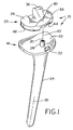
- Fig. 1 is an exploded, perspective view of an embodiment of an orthopaedic knee component of the present invention;
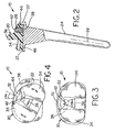
- Fig. 2 is a side, partially sectioned view of the orthopaedic knee component of Fig. 1;
- Fig. 3 is a top view of the orthopaedic knee component of Figs. 1 and 2, with the bearing located at a neutral position;
- Fig. 4 is a top view of the orthopaedic knee component of Figs. 1-3, with the bearing in a rotated position;
- Fig. 5 is a side view of the orthopaedic knee component of Figs. 1-4, implanted within a tibia and engaged with a femoral component;
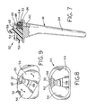
- Fig. 6 is an exploded, perspective view of another embodiment of an orthopaedic knee component of the present invention;
- Fig. 7 is a side, partially sectioned view of the orthopaedic knee component of Fig. 6;
- Fig. 8 is a top view of the orthopaedic knee component of Figs. 6 and 7, with the bearing in a neutral position;
- Fig. 9 is a top view of the orthopaedic knee component of Figs. 6-8, with the bearing in a rotated position; and
- Fig. 10 is a side view of the orthopaedic knee component of Figs. 6-9, implanted within a tibia and engaged with a femoral component.
- Corresponding reference characters indicate corresponding parts throughout the several views. The exemplifications set out herein illustrate one preferred embodiment of the invention, in one form, and such exemplifications are not to be construed as limiting the scope of the invention in any manner.
- Referring now to the drawings, and more particularly to Figs. 1-5, there is shown an embodiment of an orthopaedic knee component in the form of a
tibial knee component 10 which is implanted within a proximal tibia 12 (Fig. 5).Tibial knee component 10 engages with afemoral knee component 14 which is implanted within adistal femur 16. -
Tibial knee component 10 includes atibial tray 18 and abearing 20.Tibial tray 18 has a proximaltibial plateau 22 and a distally extendingstem 24.Tibial plateau 22 has a generally planar proximal surface which extends transverse (e.g., orthogonal) to alongitudinal axis 26 ofstem 24. A generally cylindricalshaped projection 28 has an internally threadedhole 30 which will be described in more detail hereinafter.Projection 28 has an axis ofrotation 40 which extends generally orthogonal totibial plateau 22. -
Tibial tray 18 also includes apost 32 which extends fromtibial plateau 22.Post 32 provides a rotational stop when tibial tray is engaged with bearing 20, as will be described in more detail hereinafter.Post 32 may have any suitable configuration. In the embodiment shown,post 32 has a surface which faces towardbearing 20 and includes two rounded shoulders to inhibit wear between post 32 and bearing 20 at the rotational limits ofbearing 20. -
Bearing 20 has an articular bearingsurface 34 for engagement withfemoral component 14.Articular bearing surface 34 is disposed on either side ofcenter projection 36. Each discrete portion of articular bearingsurface 34 on either side ofprojection 36 engages a corresponding condyle offemoral knee component 14, withprojection 36 being disposed between the condyles. -
Bearing 20 also includes a generally cylindrical shapedopening 38 in whichprojection 28 is disposed.Opening 38 andprojection 28 allow rotational movement of bearing 20 relative totibial plateau 22 about axis ofrotation 40 ofprojection 28.Opening 38 has a diameter which is just slightly larger than an outside diameter ofprojection 28, such that movement of bearing 20 in a generally radial direction relative toaxis 40 is inhibited. Avent hole 42 with a diameter which is smaller than a diameter of opening 38 is positioned generally concentric withopening 38.Vent hole 42 prevents a pressure build up within opening 38 that might tend to causebearing 20 to move in an axial direction away fromprojection 28. For example, whenprojection 28 is placed into opening 38 of bearing 20 during assembly, venthole 42 allows air to escape through to the ambient environment. Additionally, aftertibial knee implant 10 is implanted, bodily liquid may seep into opening 38 on the proximal side ofprojection 28 as a result of capillary action, etc. thus during use, a pressure build up may occur betweentibial plate 18 and bearing 20 at the junction betweenprojection 28 andopening 38 which may cause the bearing to be pushed out of contact withplate 18. Therefore, venthole 42 allows the bodily fluid to flow from opening 38 without a buildup of pressure. -
Bearing 20 also includes anotch 44 in which post 32 is received.Notch 44 has asurface facing post 32 with a curvature corresponding to the curvature ofpost 42 and the radius of curvature relative to the distance to axis ofrotation 40.Notch 44 and post 32 allow rotational movement of bearing 20 between a first rotational limit and a second rotational limit about axis ofrotation 40.Bearing 20 is shown in Fig. 4 at a first rotational limit which is approximately 25° relative to a neutral or symmetric position shown in Fig. 3. Thus, bearing 20 is rotationally movable through an angle α of approximately 50° between the first rotational limit and the second rotational limit (in a direction opposite to that shown in Fig. 4). -
Bearing 20 has abacking surface 46 which engages withtibial plateau 22. Backingsurface 46 is generally planar to match the corresponding generally planar configuration oftibial plateau 22. Backingsurface 46 defines a load bearing surface with tibial plateau which transfers the load imparted either by the femoral condyles engaging articular bearingsurface 34. Backingsurface 46 is sized and configured such thatbacking surface 46 is substantially entirely supported bytibial plateau 22 at any position during rotational movement between the first rotational limit and the second rotational limit. As illustrated in Fig. 3, backingsurface 46 of bearing 20 is entirely supported bytibial plateau 22 when bearing 20 is at a neutral position. Similarly, backingsurface 46 is substantially entirely supported bytibial plateau 22 when bearing 20 is at a first rotational limit (Fig. 4), a second rotational limit, or any position therebetween. - With a conventional tibial knee component, the tibial tray includes a notch on the posterior side such that the tibial plateau has a generally U-shape when viewed in a proximal-distal direction. Moreover, the bearing may overhang the tibial tray by a substantial amount when the bearing is at a rotational limit. On the other hand,
tibial plateau 22 of the present invention does not include a notch on the posterior side and the bearing does not overhang the tibial plateau by any appreciable amount when at a first rotational limit or a second rotational limit. Thus, bearing 20 is better supported to reduce the potential for implant deformation due to excessive overhang betweenbacking surface 46 andtibial plateau 22 is reduced. - Figs. 6-10 illustrate another embodiment of an orthopaedic knee component in the form of a
tibial knee component 50 of the present invention.Tibial knee component 50 includes abearing 52 which is similar in many respects to bearing 20 shown in Figs. 1-5.Bearing 52 is attached withtibial tray 18 shown in Figs. 1-5. -
Bearing 52 includes anarticular bearing surface 54,notch 56 andprojection 58 similar toarticular bearing surface 34,notch 44 andprojection 36 shown in the embodiment oftibial knee component 10 illustrated in Figs. 1-5. Moreover, bearing 52 includes a generally cylindrical shapedopening 60 which has a diameter slightly larger thanprojection 28 and receivesprojection 28 therein. However, bearing 52 has a thickness in the proximal-distal direction which is much thicker than bearing 20 shown in Figs. 1-5. To ensure that bearing 52 does not lift off ofprojection 28 during deep flexion of the knee joint, a fastener in the form of ashoulder bolt 62 extends throughopening 60 and threadingly engages with internally threadedhole 30 ofprojection 28.Opening 60 includes afirst diameter 64 which is just slightly larger than the diameter ofprojection 28, and asecond diameter 66 which defines ashoulder 68.Head 70 does not tighten againstshoulder 68 such that bearing 52 is free to pivot about axis ofrotation 40. A small clearance distance also exists betweenbolt head 70 andsecond diameter 66 such thatopening 60 likewise defines a vent hole for allowing a fluid such as air or a bodily liquid to exit therefrom. - While this invention has been described as having a preferred design, the present invention can be further modified within the spirit and scope of this disclosure. This application is therefore intended to cover any variations, uses, or adaptations of the invention using its general principles. Further, this application is intended to cover such departures from the present disclosure as come within known or customary practice in the art to which this invention pertains and which fall within the limits of the appended claims.
Claims (4)
- An orthopaedic knee component for implanting within a proximal tibia, comprising:a tibial tray including a proximal tibial plateau with a projection extending generally orthogonal to said tibial plateau; anda bearing coupled with said tibial plateau and having an articular bearing surface for engagement with a femoral component, said bearing being rotationally movable between a first rotational limit and a second rotational limit about an axis extending generally orthogonal to said tibial plateau, said bearing having a backing surface engaging said tibial plateau which is sized and shaped such that said backing surface is substantially entirely supported by said tibial plateau at any position during said rotational movement between said first rotation limit and said second rotational limit.
- The orthopaedic knee component of claim 1, wherein said tibial tray includes a post extending from said tibial plateau, and said bearing includes a notch in which said post is received, said post and said notch limiting said rotational movement of said bearing between said first rotational limit and said second rotational limit.
- The orthopaedic knee component of claim 2, wherein said notch extends from said backing surface.
- The orthopaedic knee component of claim 2, wherein said bearing is rotationally movable through an angle of approximately 50° between said first rotational limit and said second rotational limit.
Applications Claiming Priority (3)
| Application Number | Priority Date | Filing Date | Title |
|---|---|---|---|
| US346850 | 1999-07-02 | ||
| US09/346,850 US6319283B1 (en) | 1999-07-02 | 1999-07-02 | Tibial knee component with a mobile bearing |
| EP00202230A EP1064889B1 (en) | 1999-07-02 | 2000-06-26 | Tibial knee component with a mobile bearing |
Related Parent Applications (2)
| Application Number | Title | Priority Date | Filing Date |
|---|---|---|---|
| EP00202230.9 Division | 2000-06-26 | ||
| EP00202230A Division EP1064889B1 (en) | 1999-07-02 | 2000-06-26 | Tibial knee component with a mobile bearing |
Publications (2)
| Publication Number | Publication Date |
|---|---|
| EP1413264A2 true EP1413264A2 (en) | 2004-04-28 |
| EP1413264A3 EP1413264A3 (en) | 2005-01-19 |
Family
ID=23361286
Family Applications (2)
| Application Number | Title | Priority Date | Filing Date |
|---|---|---|---|
| EP00202230A Expired - Lifetime EP1064889B1 (en) | 1999-07-02 | 2000-06-26 | Tibial knee component with a mobile bearing |
| EP04002196A Withdrawn EP1413264A3 (en) | 1999-07-02 | 2000-06-26 | Tibial knee component with a mobile bearing |
Family Applications Before (1)
| Application Number | Title | Priority Date | Filing Date |
|---|---|---|---|
| EP00202230A Expired - Lifetime EP1064889B1 (en) | 1999-07-02 | 2000-06-26 | Tibial knee component with a mobile bearing |
Country Status (7)
| Country | Link |
|---|---|
| US (1) | US6319283B1 (en) |
| EP (2) | EP1064889B1 (en) |
| JP (1) | JP4237380B2 (en) |
| AU (1) | AU771790B2 (en) |
| CA (1) | CA2311868C (en) |
| DE (1) | DE60020641T2 (en) |
| ES (1) | ES2241544T3 (en) |
Cited By (5)
| Publication number | Priority date | Publication date | Assignee | Title |
|---|---|---|---|---|
| US7695519B2 (en) * | 2005-07-08 | 2010-04-13 | Howmedica Osteonics Corp. | Modular tibial baseplate |
| US7771484B2 (en) | 2006-02-28 | 2010-08-10 | Howmedica Osteonics Corp. | Modular tibial implant |
| WO2013142332A1 (en) * | 2012-03-21 | 2013-09-26 | Smith & Nephew, Inc. | Tibial implant having an anatomic stem |
| US10102309B2 (en) | 2011-07-20 | 2018-10-16 | Smith & Nephew, Inc. | Systems and methods for optimizing fit of an implant to anatomy |
| US11090120B2 (en) | 2010-08-13 | 2021-08-17 | Smith & Nephew, Inc. | Systems and methods for optimizing parameters of orthopaedic procedures |
Families Citing this family (67)
| Publication number | Priority date | Publication date | Assignee | Title |
|---|---|---|---|---|
| US6875235B2 (en) * | 1999-10-08 | 2005-04-05 | Bret A. Ferree | Prosthetic joints with contained compressible resilient members |
| DE19950112A1 (en) * | 1999-10-18 | 2001-04-19 | Plus Endoprothetik Ag Rotkreuz | Knee joint endoprosthesis |
| US7635390B1 (en) | 2000-01-14 | 2009-12-22 | Marctec, Llc | Joint replacement component having a modular articulating surface |
| US6440152B1 (en) * | 2000-07-28 | 2002-08-27 | Microvena Corporation | Defect occluder release assembly and method |
| US6558426B1 (en) | 2000-11-28 | 2003-05-06 | Medidea, Llc | Multiple-cam, posterior-stabilized knee prosthesis |
| US6719800B2 (en) | 2001-01-29 | 2004-04-13 | Zimmer Technology, Inc. | Constrained prosthetic knee with rotating bearing |
| US6485519B2 (en) | 2001-01-29 | 2002-11-26 | Bristol-Myers Squibb Company | Constrained prosthetic knee with rotating bearing |
| DE10109804C2 (en) * | 2001-03-01 | 2003-04-03 | Mathys Medizinaltechnik Ag Bet | joint prosthesis |
| US20080140212A1 (en) * | 2001-05-15 | 2008-06-12 | Robert Metzger | Elongated femoral component |
| US6589283B1 (en) * | 2001-05-15 | 2003-07-08 | Biomet, Inc. | Elongated femoral component |
| DE20108394U1 (en) * | 2001-05-18 | 2002-09-26 | KERAMED Medizintechnik GmbH, 07646 Mörsdorf | Knee replacement |
| US7708741B1 (en) | 2001-08-28 | 2010-05-04 | Marctec, Llc | Method of preparing bones for knee replacement surgery |
| DE10200263B4 (en) * | 2002-01-07 | 2007-01-25 | Plus Orthopedics Ag | Tibial component of a knee joint endoprosthesis |
| FR2835178B1 (en) * | 2002-01-31 | 2004-12-03 | Jacques Marie Rousseau | TIBIAL PROSTHETIC ASSEMBLY FOR SLIDING KNEE PROSTHESIS |
| US20040034432A1 (en) * | 2002-02-11 | 2004-02-19 | Dean Hughes | Mobile bearing tibial base prosthetic devices employing oxidized zirconium surfaces |
| CA2424732C (en) * | 2002-04-10 | 2009-05-26 | Biomedical Engineering Trust I | Prosthetic knee with removable stop pin for limiting anterior sliding movement of bearing |
| US20040002767A1 (en) * | 2002-06-28 | 2004-01-01 | Joseph Wyss | Modular knee joint prosthesis |
| FR2842411A1 (en) * | 2002-07-19 | 2004-01-23 | Dedienne Sante | Total knee prosthesis has intermediate plate able to pivot relative to tibial component by means of engaging stud and cavity |
| AU2003287190A1 (en) | 2002-10-23 | 2004-05-13 | Alastair J. T. Clemow | Modular femoral component for a total knee joint replacement for minimally invasive implantation |
| US7008454B2 (en) * | 2003-04-09 | 2006-03-07 | Biomedical Engineering Trust I | Prosthetic knee with removable stop pin for limiting anterior sliding movement of bearing |
| US7195645B2 (en) * | 2003-07-11 | 2007-03-27 | Depuy Products, Inc. | In vivo joint space measurement device and method |
| ATE461679T1 (en) * | 2003-07-17 | 2010-04-15 | Exactech Inc | MOVABLE RESILIENT KNEE PROSTHESIS |
| US7708782B2 (en) * | 2003-07-17 | 2010-05-04 | Exactech, Inc. | Mobile bearing knee prosthesis |
| US7261740B2 (en) * | 2003-10-29 | 2007-08-28 | Wright Medical Technology, Inc. | Tibial knee prosthesis |
| FR2863481B1 (en) * | 2003-12-15 | 2006-11-10 | Biomet Merck France | ANTERO-POSTERO-STABILIZED KNEE PROSTHESIS WITH SWIVEL TIBIAL PLATE |
| EP1574185B1 (en) * | 2004-03-09 | 2012-05-23 | Zimmer Technology, Inc. | Tibial knee component with a mobile bearing |
| US7175666B2 (en) * | 2004-04-30 | 2007-02-13 | Zimmer Technology, Inc. | Modular implant with a micro-motion damper |
| US20060184176A1 (en) * | 2005-02-17 | 2006-08-17 | Zimmer Technology, Inc. | Tibial trialing assembly and method of trialing a tibial implant |
| US8002777B2 (en) * | 2005-06-09 | 2011-08-23 | Biomet Manufacturing Corp. | Instrumentation and method for implanting a curved stem tibial tray |
| US7842008B2 (en) * | 2005-11-21 | 2010-11-30 | Becton, Dickinson And Company | Intradermal delivery device |
| US8211181B2 (en) * | 2005-12-14 | 2012-07-03 | New York University | Surface guided knee replacement |
| US7947082B2 (en) * | 2006-11-09 | 2011-05-24 | Consensus Orthopedics, Inc. | System and method for joint arthroplasty |
| US8273133B2 (en) | 2007-08-27 | 2012-09-25 | Samuelson Kent M | Systems and methods for providing deeper knee flexion capabilities for knee prosthesis patients |
| US8366783B2 (en) * | 2007-08-27 | 2013-02-05 | Samuelson Kent M | Systems and methods for providing deeper knee flexion capabilities for knee prosthesis patients |
| US8382846B2 (en) * | 2007-08-27 | 2013-02-26 | Kent M. Samuelson | Systems and methods for providing deeper knee flexion capabilities for knee prosthesis patients |
| US9107769B2 (en) | 2007-08-27 | 2015-08-18 | Kent M. Samuelson | Systems and methods for providing a femoral component |
| US9872774B2 (en) | 2007-08-27 | 2018-01-23 | Connor E. Samuelson | Systems and methods for providing a femoral component having a modular stem |
| US10213826B2 (en) | 2007-08-27 | 2019-02-26 | Connor E Samuelson | Systems and methods for providing prosthetic components |
| US7628818B2 (en) * | 2007-09-28 | 2009-12-08 | Depuy Products, Inc. | Fixed-bearing knee prosthesis having interchangeable components |
| US8632600B2 (en) | 2007-09-25 | 2014-01-21 | Depuy (Ireland) | Prosthesis with modular extensions |
| US20110035017A1 (en) * | 2007-09-25 | 2011-02-10 | Depuy Products, Inc. | Prosthesis with cut-off pegs and surgical method |
| US8715359B2 (en) | 2009-10-30 | 2014-05-06 | Depuy (Ireland) | Prosthesis for cemented fixation and method for making the prosthesis |
| US8128703B2 (en) * | 2007-09-28 | 2012-03-06 | Depuy Products, Inc. | Fixed-bearing knee prosthesis having interchangeable components |
| US20090088861A1 (en) * | 2007-09-27 | 2009-04-02 | Finsbury (Development) Limited | Prosthesis |
| US9204967B2 (en) | 2007-09-28 | 2015-12-08 | Depuy (Ireland) | Fixed-bearing knee prosthesis having interchangeable components |
| US7918893B2 (en) * | 2007-09-30 | 2011-04-05 | Depuy Products, Inc. | Hinged orthopaedic prosthesis |
| EP2255755B1 (en) | 2007-11-02 | 2013-03-27 | Biomet UK Limited | Prosthesis for simulating natural kinematics |
| US8192498B2 (en) | 2008-06-30 | 2012-06-05 | Depuy Products, Inc. | Posterior cructiate-retaining orthopaedic knee prosthesis having controlled condylar curvature |
| US8206451B2 (en) | 2008-06-30 | 2012-06-26 | Depuy Products, Inc. | Posterior stabilized orthopaedic prosthesis |
| US8236061B2 (en) | 2008-06-30 | 2012-08-07 | Depuy Products, Inc. | Orthopaedic knee prosthesis having controlled condylar curvature |
| US9168145B2 (en) | 2008-06-30 | 2015-10-27 | Depuy (Ireland) | Posterior stabilized orthopaedic knee prosthesis having controlled condylar curvature |
| US8187335B2 (en) | 2008-06-30 | 2012-05-29 | Depuy Products, Inc. | Posterior stabilized orthopaedic knee prosthesis having controlled condylar curvature |
| US9119723B2 (en) | 2008-06-30 | 2015-09-01 | Depuy (Ireland) | Posterior stabilized orthopaedic prosthesis assembly |
| US8828086B2 (en) | 2008-06-30 | 2014-09-09 | Depuy (Ireland) | Orthopaedic femoral component having controlled condylar curvature |
| AU2015249142B2 (en) * | 2009-06-10 | 2017-02-16 | Kent M. Samuelson | Systems and methods for providing deeper knee flexion capabilities for knee prosthesis patients |
| US9011547B2 (en) | 2010-01-21 | 2015-04-21 | Depuy (Ireland) | Knee prosthesis system |
| US8545571B2 (en) | 2010-07-30 | 2013-10-01 | Howmedica Osteonics Corp. | Stabilized knee prosthesis |
| US8747479B2 (en) | 2011-04-26 | 2014-06-10 | Michael A. McShane | Tibial component |
| US8617250B2 (en) * | 2011-06-17 | 2013-12-31 | Biomet Manufacturing, Llc | Revision knee tibial locking mechanism |
| US8734523B2 (en) | 2012-05-31 | 2014-05-27 | Howmedica Osteonics Corp. | Limited motion tibial bearing |
| GB2507640B (en) | 2012-09-10 | 2015-08-26 | Acumed Llc | Radial head prosthesis with floating articular member |
| GB2512609A (en) * | 2013-04-03 | 2014-10-08 | Fitzbionics Ltd | Total knee replacement prosthesis assembly |
| US9763792B2 (en) | 2015-10-01 | 2017-09-19 | Acumed Llc | Radial head prosthesis with rotate-to-lock interface |
| US10736748B2 (en) | 2018-05-02 | 2020-08-11 | Depuy Ireland Unlimited Company | Orthopaedic prosthetic system for a hinged-knee prosthesis |
| US11033396B2 (en) | 2019-02-05 | 2021-06-15 | Depuy Ireland Unlimited Company | Orthopaedic prosthetic system for a rotating hinged-knee prosthesis |
| US11116641B2 (en) | 2019-02-05 | 2021-09-14 | Depuy Ireland Unlimited Company | Orthopaedic prosthetic system for a rotating hinged-knee prosthesis |
| CN114010375B (en) * | 2022-01-06 | 2022-06-14 | 北京爱康宜诚医疗器材有限公司 | Knee joint prosthesis and processing method thereof |
Family Cites Families (71)
| Publication number | Priority date | Publication date | Assignee | Title |
|---|---|---|---|---|
| US4085466A (en) | 1974-11-18 | 1978-04-25 | National Research Development Corporation | Prosthetic joint device |
| US4301553A (en) | 1975-08-15 | 1981-11-24 | United States Surgical Corporation | Prosthetic knee joint |
| US4219893A (en) | 1977-09-01 | 1980-09-02 | United States Surgical Corporation | Prosthetic knee joint |
| US4094017A (en) | 1977-02-16 | 1978-06-13 | Larry Stanford Matthews | Knee joint prosthesis with patellar-femoral contact |
| US4136405A (en) | 1977-04-29 | 1979-01-30 | Zimmer U.S.A. | Rotational offset knee prosthesis |
| US4216549A (en) | 1977-06-02 | 1980-08-12 | Purdue Research Foundation | Semi-stable total knee prosthesis |
| US4470158A (en) | 1978-03-10 | 1984-09-11 | Biomedical Engineering Corp. | Joint endoprosthesis |
| US4224697A (en) | 1978-09-08 | 1980-09-30 | Hexcel Corporation | Constrained prosthetic knee |
| US4224696A (en) | 1978-09-08 | 1980-09-30 | Hexcel Corporation | Prosthetic knee |
| US4257129A (en) | 1979-05-21 | 1981-03-24 | Volz Robert G | Prosthetic knee joint tibial implant |
| US4309778A (en) | 1979-07-02 | 1982-01-12 | Biomedical Engineering Corp. | New Jersey meniscal bearing knee replacement |
| FR2465470A1 (en) | 1979-08-07 | 1981-03-27 | Gauthier Georges | Articulated joint surgical prosthesis - has twin spherical surfaces in each mating part with prolongations for lateral movement |
| US4262368A (en) | 1979-09-24 | 1981-04-21 | Wright Manufacturing Company | Rotating and hinged knee prosthesis |
| JPS6077752A (en) | 1983-09-30 | 1985-05-02 | 東海林 宏 | Meniscal artificial knee joint |
| US4634444A (en) | 1984-02-09 | 1987-01-06 | Joint Medical Products Corporation | Semi-constrained artificial joint |
| SE450460B (en) | 1984-11-28 | 1987-06-29 | Albrektsson Bjoern | DEVICE IN ARTIFICIAL MENISH FOR A KNEE JOINT PROTECTION |
| GB8432267D0 (en) | 1984-12-20 | 1985-01-30 | Thackray C F Ltd | Knee prosthesis |
| US4888021A (en) | 1988-02-02 | 1989-12-19 | Joint Medical Products Corporation | Knee and patellar prosthesis |
| US5011496A (en) | 1988-02-02 | 1991-04-30 | Joint Medical Products Corporation | Prosthetic joint |
| US5171283A (en) | 1989-07-11 | 1992-12-15 | Biomedical Engineering Trust | Compound shape rotating bearing |
| GB9005496D0 (en) | 1990-03-12 | 1990-05-09 | Howmedica | Tibial component for a replacement knee prosthesis and total knee prosthesis incorporating such a component |
| US5358531A (en) | 1990-06-12 | 1994-10-25 | British Technology Group Limited | Prosthetic knee joint devices |
| FR2663536B1 (en) * | 1990-06-22 | 1998-02-13 | Implants Instr Ch Fab | TOTAL SLIDING TYPE KNEE PROSTHESIS. |
| FR2664492A1 (en) | 1990-07-11 | 1992-01-17 | Bousquet Gilles | BICONDYLIAN KNEE PROSTHESIS. |
| US5370701A (en) | 1990-09-28 | 1994-12-06 | Arch Development Corporation | Rotating/sliding contrained prosthetic knee |
| CA2078228C (en) | 1990-11-14 | 2000-04-11 | Lawrence Pottenger | Improved floating bearing prosthetic knee |
| GB9314839D0 (en) | 1993-07-16 | 1993-09-01 | Walker Peter S | Prosthesis for knee replacement |
| US5609639A (en) | 1991-02-04 | 1997-03-11 | Walker; Peter S. | Prosthesis for knee replacement |
| GB9102348D0 (en) | 1991-02-04 | 1991-03-20 | Inst Of Orthopaedics The | Prosthesis for knee replacement |
| US5358527A (en) | 1991-03-22 | 1994-10-25 | Forte Mark R | Total knee prosthesis with resurfacing and posterior stabilization capability |
| US5282868A (en) | 1991-06-17 | 1994-02-01 | Andre Bahler | Prosthetic arrangement for a complex joint, especially knee joint |
| US5395401A (en) | 1991-06-17 | 1995-03-07 | Bahler; Andre | Prosthetic device for a complex joint |
| DE4202717C1 (en) | 1991-12-11 | 1993-06-17 | Dietmar Prof. Dr. 3350 Kreiensen De Kubein-Meesenburg | |
| DE4141757C1 (en) | 1991-12-18 | 1993-07-15 | Eska Medical Gmbh & Co, 2400 Luebeck, De | |
| DE59209628D1 (en) | 1992-01-14 | 1999-03-11 | Sulzer Orthopaedie Ag | Meniscal platform for artificial knee joint |
| CH686401A5 (en) | 1992-01-14 | 1996-03-29 | Wehrli Ueli Dr | Meniscus platform for an artificial knee joint. |
| NZ243181A (en) | 1992-04-23 | 1994-10-26 | Michael John Pappas | Prosthetic joint with guide means to limit articulation of a first element and bearing means to two degrees of freedom |
| DE9212879U1 (en) | 1992-09-24 | 1994-01-27 | Waldemar Link GmbH & Co, 22339 Hamburg | Knee joint endoprosthesis to replace the shin joint surfaces |
| US5344460A (en) | 1992-10-30 | 1994-09-06 | Encore Orthopedics, Inc. | Prosthesis system |
| US5314481A (en) | 1992-11-12 | 1994-05-24 | Wright Medical Technology, Inc. | Hinged knee prosthesis with extended patellar track |
| US5658342A (en) | 1992-11-16 | 1997-08-19 | Arch Development | Stabilized prosthetic knee |
| US5413604A (en) | 1992-12-24 | 1995-05-09 | Osteonics Corp. | Prosthetic knee implant for an anterior cruciate ligament deficient total knee replacement |
| US5358530A (en) | 1993-03-29 | 1994-10-25 | Zimmer, Inc. | Mobile bearing knee |
| GB2277034B (en) | 1993-04-01 | 1997-02-26 | British Tech Group | Implantable prosthetic patellar components |
| GB2278782A (en) | 1993-04-20 | 1994-12-14 | Kevin Hardinge | An improved knee arthroplasty and tibial component therefor |
| GB9310193D0 (en) | 1993-05-18 | 1993-06-30 | Walker Peter S | Knee prosthesis with femoral,tibial conformity |
| IT1264820B1 (en) | 1993-07-28 | 1996-10-10 | Cremascoli G Srl | TOTAL KNEE PROSTHESIS TOTAL KNEE PROSTHESIS |
| FR2714819B1 (en) | 1994-01-10 | 1996-03-08 | Billy Jean Louis | Knee prosthesis. |
| GB9403165D0 (en) | 1994-02-18 | 1994-04-06 | Johnson Robert | Knee joint prostheses |
| DE4409787A1 (en) * | 1994-03-22 | 1995-09-28 | Alphanorm Medizintechnik Gmbh | Knee prosthesis |
| GB9405746D0 (en) | 1994-03-23 | 1994-05-11 | Howmedica | Prosthetic patello femoral joint assembly |
| GB9405883D0 (en) | 1994-03-24 | 1994-05-11 | Corin Medical Ltd | Prosthesis assembly |
| FR2718015B1 (en) | 1994-03-29 | 1996-07-05 | Bouvet Jean Claude | Improvement to knee prostheses. |
| GB9407153D0 (en) | 1994-04-11 | 1994-06-01 | Corin Medical Ltd | Unicompartmental knee prosthesis |
| FR2719466B1 (en) | 1994-05-04 | 1997-06-06 | Ysebaert Sa | Knee prosthesis with movable meniscus. |
| GB9413607D0 (en) | 1994-07-06 | 1994-08-24 | Goodfellow John W | Endoprosthetic knee joint device |
| GB9415180D0 (en) | 1994-07-28 | 1994-09-21 | Walker Peter S | Stabilised mobile bearing knee |
| GB9418492D0 (en) | 1994-09-14 | 1994-11-02 | Goodfellow John W | Prosthetic knee joint device |
| US5549689A (en) | 1994-11-28 | 1996-08-27 | Epstein; Norman | Prosthetic knee |
| US5683468A (en) | 1995-03-13 | 1997-11-04 | Pappas; Michael J. | Mobile bearing total joint replacement |
| FR2735017B1 (en) * | 1995-06-08 | 1997-08-14 | Groupe Lepine | KNEE PROSTHESIS WITH MOBILE TRAY |
| GB2304051B (en) | 1995-08-09 | 1999-01-27 | Corin Medical Ltd | A knee prosthesis |
| GB2312166A (en) | 1996-04-17 | 1997-10-22 | Finsbury | Tibial plate for an endoprosthetic knee |
| GB2312167A (en) | 1996-04-17 | 1997-10-22 | Finsbury | An endoprosthetic knee |
| GB2312168B (en) | 1996-04-17 | 1999-11-03 | Finsbury | Meniscal knee prosthesis |
| GB2312377B (en) | 1996-04-24 | 2000-04-26 | Roozbeh Shirandami | Prosthetic knee joint with anterior posterior sliding action |
| GB9609609D0 (en) | 1996-05-08 | 1996-07-10 | Midland International Orthopae | Knee prosthesis |
| GB9611060D0 (en) | 1996-05-28 | 1996-07-31 | Howmedica | Tibial element for a replacment knee prosthesis |
| US6123728A (en) * | 1997-09-17 | 2000-09-26 | Smith & Nephew, Inc. | Mobile bearing knee prosthesis |
| FR2768613B1 (en) * | 1997-09-23 | 1999-12-17 | Tornier Sa | KNEE PROSTHESIS WITH ROTATABLE PLATFORM |
| US6053945A (en) * | 1997-09-25 | 2000-04-25 | Johnson & Johnson Professional, Inc. | Joint prosthesis having controlled rotation |
-
1999
- 1999-07-02 US US09/346,850 patent/US6319283B1/en not_active Expired - Lifetime
-
2000
- 2000-06-16 CA CA002311868A patent/CA2311868C/en not_active Expired - Lifetime
- 2000-06-26 DE DE60020641T patent/DE60020641T2/en not_active Expired - Lifetime
- 2000-06-26 EP EP00202230A patent/EP1064889B1/en not_active Expired - Lifetime
- 2000-06-26 ES ES00202230T patent/ES2241544T3/en not_active Expired - Lifetime
- 2000-06-26 EP EP04002196A patent/EP1413264A3/en not_active Withdrawn
- 2000-06-28 AU AU42737/00A patent/AU771790B2/en not_active Expired
- 2000-06-28 JP JP2000200109A patent/JP4237380B2/en not_active Expired - Lifetime
Cited By (9)
| Publication number | Priority date | Publication date | Assignee | Title |
|---|---|---|---|---|
| US7695519B2 (en) * | 2005-07-08 | 2010-04-13 | Howmedica Osteonics Corp. | Modular tibial baseplate |
| US7771484B2 (en) | 2006-02-28 | 2010-08-10 | Howmedica Osteonics Corp. | Modular tibial implant |
| US11090120B2 (en) | 2010-08-13 | 2021-08-17 | Smith & Nephew, Inc. | Systems and methods for optimizing parameters of orthopaedic procedures |
| US10102309B2 (en) | 2011-07-20 | 2018-10-16 | Smith & Nephew, Inc. | Systems and methods for optimizing fit of an implant to anatomy |
| US10922448B2 (en) | 2011-07-20 | 2021-02-16 | Smith & Nephew, Inc. | Systems and methods for optimizing fit of an implant to anatomy |
| US11868681B2 (en) | 2011-07-20 | 2024-01-09 | Smith & Nephew, Inc. | Systems and methods for optimizing fit of an implant to anatomy |
| US11977817B2 (en) | 2011-07-20 | 2024-05-07 | Smith & Nephew, Inc. | Systems and methods for optimizing fit of an implant to anatomy |
| WO2013142332A1 (en) * | 2012-03-21 | 2013-09-26 | Smith & Nephew, Inc. | Tibial implant having an anatomic stem |
| AU2013235385B2 (en) * | 2012-03-21 | 2017-07-13 | Smith & Nephew, Inc. | Tibial implant having an anatomic stem |
Also Published As
| Publication number | Publication date |
|---|---|
| EP1064889A2 (en) | 2001-01-03 |
| DE60020641T2 (en) | 2006-05-04 |
| JP4237380B2 (en) | 2009-03-11 |
| US6319283B1 (en) | 2001-11-20 |
| EP1413264A3 (en) | 2005-01-19 |
| CA2311868C (en) | 2008-10-07 |
| EP1064889B1 (en) | 2005-06-08 |
| DE60020641D1 (en) | 2005-07-14 |
| ES2241544T3 (en) | 2005-11-01 |
| AU771790B2 (en) | 2004-04-01 |
| JP2001029370A (en) | 2001-02-06 |
| AU4273700A (en) | 2001-01-04 |
| EP1064889A3 (en) | 2002-01-09 |
| CA2311868A1 (en) | 2001-01-02 |
Similar Documents
| Publication | Publication Date | Title |
|---|---|---|
| US6319283B1 (en) | Tibial knee component with a mobile bearing | |
| US6210444B1 (en) | Tibial knee component with a mobile bearing | |
| US6210445B1 (en) | Tibial knee component with a mobile bearing | |
| US6217618B1 (en) | Tibial knee component with a mobile bearing | |
| US5957979A (en) | Mobile bearing knee with metal on metal interface | |
| US6485519B2 (en) | Constrained prosthetic knee with rotating bearing | |
| US8888857B2 (en) | Constrained prosthetic knee with rotating bearing | |
| US5989293A (en) | Acetabular cup kit for use during hip replacement surgery | |
| EP0732091B1 (en) | Mobile bearing total joint replacement | |
| US20030009228A1 (en) | Constrained prosthetic knee with rotating bearing | |
| EP1132063A2 (en) | Posterior stabilized knee replacement with dislocation prevention features | |
| HK1061344A (en) | Mobile bearing knee with metal on metal interface |
Legal Events
| Date | Code | Title | Description |
|---|---|---|---|
| PUAI | Public reference made under article 153(3) epc to a published international application that has entered the european phase |
Free format text: ORIGINAL CODE: 0009012 |
|
| 17P | Request for examination filed |
Effective date: 20040202 |
|
| AC | Divisional application: reference to earlier application |
Ref document number: 1064889 Country of ref document: EP Kind code of ref document: P |
|
| AK | Designated contracting states |
Kind code of ref document: A2 Designated state(s): DE ES FR GB IT |
|
| RIN1 | Information on inventor provided before grant (corrected) |
Inventor name: MILLER, CLAYTON R. Inventor name: MCLEAN, CHRISTOPHER Inventor name: PATMORE, AUDREY Inventor name: TANAMAL, LINGGAWATI Inventor name: INSALL, JOHN |
|
| PUAL | Search report despatched |
Free format text: ORIGINAL CODE: 0009013 |
|
| AK | Designated contracting states |
Kind code of ref document: A3 Designated state(s): DE ES FR GB IT |
|
| 17Q | First examination report despatched |
Effective date: 20050520 |
|
| AKX | Designation fees paid |
Designated state(s): DE ES FR GB IT |
|
| STAA | Information on the status of an ep patent application or granted ep patent |
Free format text: STATUS: THE APPLICATION IS DEEMED TO BE WITHDRAWN |
|
| 18D | Application deemed to be withdrawn |
Effective date: 20051001 |
|
| RIN1 | Information on inventor provided before grant (corrected) |
Inventor name: MCLEAN, CHRISTOPHER Inventor name: PATMORE, AUDREY Inventor name: INSALL, JOHN Inventor name: TANAMAL, LINGGAWATI Inventor name: MILLER, CLAYTON R. |