EP1412611B1 - Umbilical termination assembly and launching system related application information - Google Patents
Umbilical termination assembly and launching system related application information Download PDFInfo
- Publication number
- EP1412611B1 EP1412611B1 EP02747866.8A EP02747866A EP1412611B1 EP 1412611 B1 EP1412611 B1 EP 1412611B1 EP 02747866 A EP02747866 A EP 02747866A EP 1412611 B1 EP1412611 B1 EP 1412611B1
- Authority
- EP
- European Patent Office
- Prior art keywords
- launch system
- subsea
- winch
- hydraulic
- boom
- Prior art date
- Legal status (The legal status is an assumption and is not a legal conclusion. Google has not performed a legal analysis and makes no representation as to the accuracy of the status listed.)
- Expired - Lifetime
Links
- 239000004020 conductor Substances 0.000 claims description 19
- 238000012360 testing method Methods 0.000 claims description 16
- 229910000831 Steel Inorganic materials 0.000 claims description 11
- 239000000835 fiber Substances 0.000 claims description 10
- 239000010959 steel Substances 0.000 claims description 10
- VNWKTOKETHGBQD-UHFFFAOYSA-N methane Chemical compound C VNWKTOKETHGBQD-UHFFFAOYSA-N 0.000 claims description 7
- 239000000463 material Substances 0.000 claims description 6
- 230000003287 optical effect Effects 0.000 claims description 6
- 229920000049 Carbon (fiber) Polymers 0.000 claims description 3
- 239000004917 carbon fiber Substances 0.000 claims description 3
- 239000007924 injection Substances 0.000 claims description 3
- 238000002347 injection Methods 0.000 claims description 3
- XLYOFNOQVPJJNP-UHFFFAOYSA-N water Substances O XLYOFNOQVPJJNP-UHFFFAOYSA-N 0.000 claims description 3
- 229910052782 aluminium Inorganic materials 0.000 claims description 2
- XAGFODPZIPBFFR-UHFFFAOYSA-N aluminium Chemical compound [Al] XAGFODPZIPBFFR-UHFFFAOYSA-N 0.000 claims description 2
- 239000002131 composite material Substances 0.000 claims description 2
- 239000011152 fibreglass Substances 0.000 claims description 2
- 239000002343 natural gas well Substances 0.000 claims description 2
- 239000003129 oil well Substances 0.000 claims description 2
- 238000000034 method Methods 0.000 description 8
- 238000007667 floating Methods 0.000 description 6
- 241000191291 Abies alba Species 0.000 description 5
- 235000004507 Abies alba Nutrition 0.000 description 5
- 229910052751 metal Inorganic materials 0.000 description 5
- 239000002184 metal Substances 0.000 description 5
- 238000005096 rolling process Methods 0.000 description 5
- 241000282472 Canis lupus familiaris Species 0.000 description 4
- 238000004519 manufacturing process Methods 0.000 description 4
- 238000010276 construction Methods 0.000 description 3
- 239000007787 solid Substances 0.000 description 3
- 230000000087 stabilizing effect Effects 0.000 description 3
- PEDCQBHIVMGVHV-UHFFFAOYSA-N Glycerine Chemical compound OCC(O)CO PEDCQBHIVMGVHV-UHFFFAOYSA-N 0.000 description 2
- 238000013461 design Methods 0.000 description 2
- 239000012530 fluid Substances 0.000 description 2
- 239000003345 natural gas Substances 0.000 description 2
- 238000003860 storage Methods 0.000 description 2
- 239000010962 carbon steel Substances 0.000 description 1
- 238000004891 communication Methods 0.000 description 1
- 239000004567 concrete Substances 0.000 description 1
- 230000001419 dependent effect Effects 0.000 description 1
- 238000005553 drilling Methods 0.000 description 1
- 230000005611 electricity Effects 0.000 description 1
- 230000007613 environmental effect Effects 0.000 description 1
- 239000007789 gas Substances 0.000 description 1
- 238000003780 insertion Methods 0.000 description 1
- 230000037431 insertion Effects 0.000 description 1
- 239000003921 oil Substances 0.000 description 1
- 238000011084 recovery Methods 0.000 description 1
- 239000004576 sand Substances 0.000 description 1
- 239000003381 stabilizer Substances 0.000 description 1
- 238000000545 stagnation point adsorption reflectometry Methods 0.000 description 1
- 230000000007 visual effect Effects 0.000 description 1
- 239000002023 wood Substances 0.000 description 1
Images




Classifications
-
- E—FIXED CONSTRUCTIONS
- E21—EARTH OR ROCK DRILLING; MINING
- E21B—EARTH OR ROCK DRILLING; OBTAINING OIL, GAS, WATER, SOLUBLE OR MELTABLE MATERIALS OR A SLURRY OF MINERALS FROM WELLS
- E21B19/00—Handling rods, casings, tubes or the like outside the borehole, e.g. in the derrick; Apparatus for feeding the rods or cables
- E21B19/002—Handling rods, casings, tubes or the like outside the borehole, e.g. in the derrick; Apparatus for feeding the rods or cables specially adapted for underwater drilling
Definitions
- This invention is for a launching system, method of use, and umbilical termination assembly (UTA) usable with subsea wells and Christmas trees and related subsea equipment used in the offshore oil and natural gas industry.
- UTA umbilical termination assembly
- the invention has the advantage of being able to test and control subsea equipment in series without the need to bring the testing or control equipment, such as an umbilical termination assembly, to the surface after each test or control period.
- the present invention has been created to provide a method of safely launching and using an umbilical termination assembly for a series of tests or control situations under water.
- the present invention specifically relates an umbilical termination assembly, which can be used to continually perform subsea Christmas tree testing and control while maintained in a submerged situation.
- the invention solves a long felt need for a launch system which can be mounted on a floating vessels or even a platform, such as tension leg platforms (TLP), deep draft caisson vessels (SPAR), fixed platforms, compliant towers, semisubmersible vessels, or other floating vessels and used to launch and retrieve subsea equipment, such as an umbilical termination assembly.
- TLP tension leg platforms
- SPAR deep draft caisson vessels
- fixed platforms compliant towers
- compliant towers compliant towers
- semisubmersible vessels or other floating vessels and used to launch and retrieve subsea equipment, such as an umbilical termination assembly.
- a UTA which comprises: a lift point; a connector connected to the lift point; a guide surrounding the connector; a housing connected to the guide, and further wherein the housing comprises: a mandrel for engaging the connector and at least one interface for connecting between a member of the group: an electrical umbilical, a fiber optic cable, and a hydraulic umbilical; a plurality of flying leads connected to the housing; a base connected to the housing, and an emergency quick disconnect connected to the mandrel, comprising a hydraulic connector which engages hydraulic pistons which can then disengage a plurality of locking dogs, enabling the hydraulic connector to disengage from the UTA.
- a method of lowering a UTA or similar subsea tool to subsea equipment for control and or testing using a movable boom comprising the steps of : (1) connecting the UTA to a hydraulic conductor connected to a hydraulic system; (2) connecting the UTA to an electric conductor connected to a power system; (3) connecting the UTA to an optical conductor connected to an optical communication system; (4) removably connecting the UTA to a winch cable which is connected to a winch wherein the winch cable passes through a sheave mounted on a moveable boom in a predeployment position, wherein the boom is mounted on a vessel; (5) simultaneously, picking up the UTA using the winch, and moving the moveable boom with an actuator from the moveable boom's predeployment position to a deployed position; (6) performing a controlled descent of the UTA from the vessel to subsea equipment using the winch; (7) disconnecting interfaces from the UTA and attaching flying leads to the subsea
- Embodiments of the invention relate to a launch system and subsea tools for use during subsea operations of the present invention which can be used with a variety of production vessels and even with production platforms, such as floating production platforms.
- the embodiments relate to a deployment and retrieval vehicle, which can be attached to an offshore platform or a floating vessel and successfully eliminates the risk of collision between equipment and piping passing through the moon pool and equipment which can be successfully passed over the side of a vessel.
- This device significantly improves the health, safety and operating environment on an offshore rig or vessel while enabling continuing drilling, completion, production workover or decompletion operations. This device improves the working conditions by reducing accidents that can occur because of too many pipes and other devices passing through the moon pool of the vessel.
- the embodiments relate to a method of deploying and retrieving a subsea tool wherein the tool can be used over and over, without having to surface, to test and control wells and other subsea equipment.
- the embodiments have significant health, safety and environmental advantages over other systems which require the constant deployment and retrieval of subsea tools, such as a tree running tool mounted umbilical termination assembly or (UTA).
- subsea tools such as a tree running tool mounted umbilical termination assembly or (UTA).
- UTA tree running tool mounted umbilical termination assembly
- the embodiments can be used on a wide variety of subsea equipment, including but not limited to a subsea oil well, or subsea Christmas Tree, a subsea natural gas well, a subsea water injection well, a subsea gas injectionwell, a subseamanifold, a flowline skid, and combinations of these.
- Each launch can cause an accident, each retrieval can be an exposure to liability.
- the embodiments reduces the chance of accidents by enabling the subsea tool for control and or testing to launch one time only then remain underwater and permit testing and control in sequence with a single retrieval after the project is completed.
- a launch system for use in controlling subsea equipment which comprises, a winch mounted on a vessel; a movable boom mounted near the winch on the vessel for receiving cable from the winch and guiding that cable to a subsea tool; at least one reel mounted near the moveable boom on the vessel for storing at least one optical conductor, electrical conductor or hydraulic conductor; at least one sheave disposed on the movable boom for guiding the cable to the subsea tool; at least one actuator mounted on the vessel for pivoting the moveable boom from a predeployed position to a deployed position; a power system mounted on the vessel for the at least one optical conductor, electrical conductor or hydraulic conductor when engaged with the subsea equipment which can be used for recovery of the subsea tool after controlling of the subsea equipment.
- the actuator can be a pneumatic cylinder, an electric motor, a plurality of mechanical linkages, gears, a hydraulic cylinder, and combinations of these devices.
- the winch can be a pneumatic winch, a hydraulic winch, an electric winch, combinations of these winches, or winches with motion compensators attached.
- the most preferred winch has a rated working load capable of supporting no less then the weight of the cable and the weight of the subsea tool, which is most preferably an umbilical termination assembly or UTA as it will be referred to throughout.
- the launch system can further include a motion compensator mounted on the floating vessel.
- the motion compensator can be any number of types of usable motion compensators, such as a heave compensator.
- the launch system can utilize one or a plurality of reels.
- One reel can be used which holds both an electrical umbilical and a hydraulic umbilical.
- two or more reels can also be used with each reel using that combination of umbilicals, or separate hosting a hydraulic umbilical or an electric umbilical.
- Fiber optic cable can be used as well with the launch system for the subsea tool and one or more reels can also hold and release fiber optic cable.
- This invention has been conceived so that a launch system can be used for the controlling of the subsea equipment, particularly where that "controlling" is the connecting to and testing of subsea equipment in series while submerged.
- the most preferred subsea equipment that this system is contemplated for is the Christmas trees of oil, natural gas and injection wells.
- the launch system has a moveable boom, which can be mounted to the deck directly of the floating vessel such as with turnbuckles or the like, or it can be skid mounted, on a platform. If a platform is contemplated, one embodiment contemplates that the platform has rails mounted to it.
- the rails are disposed over wheels or rollers mounted on the deck or on yet another platform, enabling the platform to be easily movable and retractable and extendable.
- the extendable platform is contemplated to be extendable using hydraulic power, pneumatic power, mechanical power, electrical power, and manual power.
- the extendable platform can be constructed from one or more of a variety of usable materials, which can include fiberglass, steel, aluminum, and carbon fiber composite.
- the boom could be a rigid structure, and made of solid steel, which could be usable in conditions of bad weather. However, for geographic locations where weather is not as bad, a folding boom or collapsible boom is contemplated.
- the boom is also contemplated to be made from hollow tubes, or piping, as well as from square tubing or piping, or any other shape material, which can withstand offshore conditions.
- the boom is contemplated to be configured in a shape, which can be a conventional boom, having a linear shape, or any of a number of other shapes. Shapes which would work include a boom which is U-shaped, square-shaped, C-shaped, rectangularly-shaped, ellipseoidally-shaped, and triangularly-shaped.
- the most preferred embodiment contemplates an inverted U-shaped moveable boom.
- the power system usable with the launch system is contemplated to be either a hydraulic power source, a pneumatic power source, an electrical power source, or combinations of these power systems. Power also may be provided from power packs.
- the launch system can further comprise a safety cable secured to the moveable boom to keep the moveable boom from collapsing. An additional power source is contemplated to run the winch. Clamps can be used in this invention to connect together the winch cable, and the conductors or umbilicals of electricity, hydraulics and fiber optics.
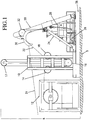
- a launch system 8 is mounted on a platform 38 having a heave compensator 10.
- the heave compensator 10 can be a hydraulically controlled heave compensator.
- a winch 12, which can be a stand-alone winch, is used to raise and lower the UTA 26 (umbilical termination assembly).
- the winch can be connected to platform 38.
- the winch 12 uses a cable 22 to raise and lower the UTA.
- a plurality of sheaves is used to guide the cable 22 from an attaching point on the winch 12 to the UTA 26.
- a first sheave 14 is an entry sheave
- a second sheave 16 is a motion compensator fixed sheave
- a third sheave 18 is the exit sheave, can be secured to a motion compensator 10.
- a fourth sheave can be used, the motion compensator 10's dynamic sheave, 17, is mounted on the motion compensator.
- FIG 3 shows the boom 20 shape as an inverted U-shape however, it could be triangularly shaped or C shaped to assist in the raising and lowering of the UTA.
- the boom 20 is movable and preferably attached to hydraulic cylinders 24 and 25.
- the hydraulic cylinders 24 and 25 (shown in FIG 5 ) are used to pivot the moveable boom 20 from a predeployed position (shown in FIG 1 ) to a deployed position (shown in FIG 2 ).
- the hydraulic cylinder 24 is secured on one end to the equipment platform 38, which is attached to deck 5 of the vessel, and on the other end the hydraulic cylinder 24 is connected to the boom 20.
- Two safety cables 28 and 29 (cable 28 is shown in FIG 1 , and both cables are shown in FIG 5 ) are used to prevent the moveable boom 20 from falling into the sea if the hydraulic cylinders fail to provide the necessary support to the boom 20.
- a cable sheave 32 is positioned on the boom 20.
- An umbilical sheave 30 is on the boom 20 and used for guiding a hydraulic umbilical 31 (which is shown in more detail in FIG 3 ) to the UTA 26.
- An electrical sheave 34 is used for guiding an electrical umbilical 33 to the UTA 26. All three sheaves are shown in Figure 3 .
- platform 38 further includes an extendable work platform 39.
- the extendable work platform 39 is preferably hydraulically extendable, and may be made from steel, or other durable material. This extendable platform may have a grate construction or may have a solid construction.
- the UTA 26 enables the testing in series of the subsea equipment while remaining submerged.
- the UTA has a lift point; which can be a pad eye.
- a connector is connected to the lift point, although a hollow cylinder can be disposed between the pad eye or lift point and the connector.
- a guide surrounds the connector.
- the guide is preferably in the shape of a funnel, by any appropriate guide means, preferably also using a self alignment key is contemplated as usable.
- the current preferred embodiment contemplates a funnel with a conical shape, with the widest part of the cone oriented to the lift point and the more narrow part of the cone oriented in the other direction.
- a housing is contemplated connecting to the guide.
- the housing is preferably made from steel, like the funnel and the lift point.
- the housing further contains a mandrel for engaging the connector and at least one interface for connecting between one or more umbilicals or fiber optics, such as electrical umbilicals, a fiber optic cable, and hydraulic umbilicals.
- the UTA has a plurality of flying leads connected to the housing.
- the housing then sits on a base, which can be a plate of steel or metal, or a perforated structure, like a H design or a grid design.
- This base can be distanced away from the housing by using steel I-beams or similar means which would provide a space between the housing and the base.
- the use of the legs, or supports provides space so that a diver or ROV could obtain easy insertion into the UTA to connect or quickly disconnect the UTA from a Christmas tree, such as in the case of an impending Tsunami or hurricane.
- the emergency quick disconnect feature of the UTA is a component or hydraulic connector which is connected to the mandrel.
- This quick disconnect feature includes a hydraulic connector which engages hydraulic pistons which can then disengage a plurality of locking dogs, enabling the hydraulic connector to disengage from the UTA. It is possible that other than a hydraulic connector could be used for the quick disconnect feature, such as a mechanical connector or electrical connector or combinations of those connectors.
- the UTA has a further embodiment, wherein the base may further have at least one, and a number, up to 20 or more, and most preferably four stabilizing connections.
- the stabilizing connections are located on each corner of the base to add stability to the UTA.
- the UTA base is contemplated to have as an embodiment, the ability to provide storage for one or more of electrical, hydraulic or fiber optic flying leads. Additionally, it is contemplated that the base is constructed from a structurally sturdy material such as concrete, carbon fiber, steel, or combinations of these.
- the UTA 26 is shown connected to the cable 22 by a pad eye 68.
- the pad eye 68 is secured to a hollow shaft 70, which optionally connects to the hydraulic connector 74 (shown in FIG 6 ).
- a guide 76 having the preferred shape of a funnel partially surrounds the hollow shaft 70.
- the hydraulic connector 74 sits within the guide 76.
- the guide rests on housing 66, which contains a mandrel, which is shown in FIG 7 . Also in FIG 7 , are shown interfaces between the electrical and hydraulic umbilical to the junction plates.
- the electrical interface 85 and the hydraulic interface 81 can be connected to the subsea equipment easily using an ROV or a diver.
- housing 66 is connected on the other end to the base 62 of the UTA 26.
- the sides of the base 62 may be used as storage for the hydraulic flying leads and electrical flying leads (not shown) of the UTA 26.
- FIG 3 shows a front view of a boom 20 with three sheaves, 30,32, and 34.
- Boom 20 is shown in this embodiment as connected to the platform by pivots or turnbuckles 58 and 56.
- a clamp 72 is used to connect together, the electrical umbilical 33, hydraulic umbilical 31 and winch cables 22.
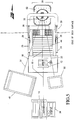
- FIG 4 shows a top view of the launch system 8 wherein platform 38 has rolling platform 39 constrained within the confines of platform 38.
- Rolling platform 39 is shown in the deployed position.
- the rolling platform 39 can be an optional component of the launching system 8 and helpful from a safety perspective.
- Rolling platform 39 can optionally roll on rails (41), but it can contain rails mounted on the extendable platform 39 and roll on rollers 42 secured to the deck
- FIG 2 shows the rail embodiment, with rail 41 represented.
- the rolling platform 39 can have a grating 40, or perforated metal structure, which can be used to support personnel or equipment.
- FIG 5 shows a winch power pack, or power system 36, which is connected to and runs winch 12. This FIG 5 also provides an embodiment, wherein platform 39 is covered with wood slats 44.
- FIG 5 also shows a hydraulic umbilical reel 48 connected to the hydraulic umbilical 31.
- An electrical down line 50, or electrical umbilical reel 50 connects to electrical umbilical 33.
- FIG 5 also shows hydraulic cylinders 24,25, safety cables 28,29 as well as boom 20.
- base 62 of the UTA 26 is preferably steel.
- the base can be either of a plate construction or possibly a sturdy frame made of solid steel I-beams welded together or a perforated metal structure.
- the frame may be tubular metal.
- a platform 38 with extension 39 is also shown.
- Motion compensator 10 is between winch 12 and the cable sheave 32 and cable 22 runs through the sheave 32.
- FIG. 6 shows the UTA 26 having a pad eye 68 for connecting to the winch cable 22 and the hollow cylinder 70.
- the UTA 26 has a base 62, with stabilizing connectors, which could be pad eyes at each corner of the base 63, 64 and 65, with the fourth connector not shown. Only one stabilizer connector may be used on the UTA base.
- Hydraulic connector 74 has a guide funnel 76, which is supported by at least three gussets 77, 78, and 79. In this Figure, three gussets are shown preferably 4 gussets would be used.
- An alignment key 80 is used to align the connector 74 as it goes into the guide funnel 76.
- the connector 74 acts as an emergency quick disconnect mechanism.
- the connector 74 engages the mandrel. When release is needed, the connector 74 receives hydraulic fluid. The hydraulic fluid flows against piston, which then pushes and cause the plurality locking dogs to releases to that the hydraulic connector can be disengaged from the UTA.
- a hydraulic quick connect plate 82 attaches to the hydraulic umbilical 31.
- a hydraulic interface 83 connected to a hydraulic flying lead 52. Electric flying leads 54 are secured to an electrical interface 85.
- a plurality of housing supports 100,101, 102,103, 104, and 105 can be used to keep the housing 66 and hydraulic connector 74 apart from the base 62, so that a diver or an ROV has accessibility to the hydraulic or electric flying leads for easy connection. These supports help the connector 74 remain the required distance away from the platform for ease of use with an ROV.
- FIG 7 is a detailed side view of the connector 74.
- Electric power connector 84 engages with a subsea matable electrical connector 88, via the hollow shaft 70.
- a hydraulic connector-locking ring 86 typically has 8-10 locking dogs, and locks the connector onto the mandrel 106. Up to 12 hydraulic connectors can be used for this size body but additional hydraulic connectors can be used on larger connector bodies.
- a visual indicator 87 can be used to insure that secure locking occurs for the connectors.
- seals such as metal-to-metal seals, elastomeric seals, or a combination of seals can be used with any one or all of the connections.
- 5,08 to 30,48 cm (2 inch to 12 inch) connectors are used.
- a 22,86 cm (9 inch) connector is the most preferred embodiment.
- Cable of various materials can be used. It is contemplated to use steel cable, non-rotating cable, synthetic man-made fiber cables and other for this launching system.
- a method for lowering a UTA to subsea equipment using a movable boom comprising the steps of : (1) connecting the UTA to a hydraulic conductor connected to a hydraulic system; (2) connecting the UTA to an electric conductor connected to a power system; (3) removably connecting the UTA to a winch cable which is connected to a winch wherein the winch cable passes through a sheave mounted on a moveable boom in a predeployment position, wherein the boom is mounted on a vessel; (4) simultaneously, picking up the UTA using the winch, and moving the moveable boom with an actuator from the moveable boom's predeployment position to a deployed position ; (5) performing a controlled descent of the UTA from the vessel to subsea equipment using the winch; (6) disconnecting interfaces from the UTA and attaching flying leads to the subsea equipment; (7) controlling and testing the subsea equipment via the UTA from the vessel; and (8) disengaging the interfaces from
- the method further contemplates having the step of connecting a fiber optic cable to the UTA.
- the interfaces can be connected to one or more of the following devices: a pressure transducer, a temperature transducer; a flow sensor, a choke, a pig detector, a sand detector, a smart well device, or combinations of these devices. Additionally, in the connecting step for the interfaces, the interfaces can be connected to a subsea control module, a running tool; a flying lead deployment running tool, a choke running tool, an insert tool, and combinations of these.
- the interfaces can be engaged or disconnected using an ROV or a diver or both.
Landscapes
- Engineering & Computer Science (AREA)
- Geology (AREA)
- Life Sciences & Earth Sciences (AREA)
- Mining & Mineral Resources (AREA)
- Physics & Mathematics (AREA)
- Environmental & Geological Engineering (AREA)
- Fluid Mechanics (AREA)
- Mechanical Engineering (AREA)
- General Life Sciences & Earth Sciences (AREA)
- Geochemistry & Mineralogy (AREA)
- Earth Drilling (AREA)
- Bridges Or Land Bridges (AREA)
- Details Of Indoor Wiring (AREA)
- Forklifts And Lifting Vehicles (AREA)
Description
- This invention is for a launching system, method of use, and umbilical termination assembly (UTA) usable with subsea wells and Christmas trees and related subsea equipment used in the offshore oil and natural gas industry. The invention has the advantage of being able to test and control subsea equipment in series without the need to bring the testing or control equipment, such as an umbilical termination assembly, to the surface after each test or control period.
- The present invention has been created to provide a method of safely launching and using an umbilical termination assembly for a series of tests or control situations under water.
- The present invention specifically relates an umbilical termination assembly, which can be used to continually perform subsea Christmas tree testing and control while maintained in a submerged situation.
- The invention solves a long felt need for a launch system which can be mounted on a floating vessels or even a platform, such as tension leg platforms (TLP), deep draft caisson vessels (SPAR), fixed platforms, compliant towers, semisubmersible vessels, or other floating vessels and used to launch and retrieve subsea equipment, such as an umbilical termination assembly.
- According to the present invention there is provided a launch system according to claim 1. Preferred features of the present invention are recited in the dependent claims.
- There is also described a UTA which comprises: a lift point; a connector connected to the lift point; a guide surrounding the connector; a housing connected to the guide, and further wherein the housing comprises: a mandrel for engaging the connector and at least one interface for connecting between a member of the group: an electrical umbilical, a fiber optic cable, and a hydraulic umbilical; a plurality of flying leads connected to the housing; a base connected to the housing, and an emergency quick disconnect connected to the mandrel, comprising a hydraulic connector which engages hydraulic pistons which can then disengage a plurality of locking dogs, enabling the hydraulic connector to disengage from the UTA.
- Finally there is also described a method of lowering a UTA or similar subsea tool to subsea equipment for control and or testing using a movable boom wherein the method comprises the steps of : (1) connecting the UTA to a hydraulic conductor connected to a hydraulic system; (2) connecting the UTA to an electric conductor connected to a power system; (3) connecting the UTA to an optical conductor connected to an optical communication system; (4) removably connecting the UTA to a winch cable which is connected to a winch wherein the winch cable passes through a sheave mounted on a moveable boom in a predeployment position, wherein the boom is mounted on a vessel; (5) simultaneously, picking up the UTA using the winch, and moving the moveable boom with an actuator from the moveable boom's predeployment position to a deployed position; (6) performing a controlled descent of the UTA from the vessel to subsea equipment using the winch; (7) disconnecting interfaces from the UTA and attaching flying leads to the subsea equipment; (8) controlling and testing the subsea equipment via the UTA from the vessel; and (9) disengaging the interfaces from the subsea equipment, once control and testing is complete, for use on a subsequent subsea equipment.
-
-
FIG 1 is a side view of an embodiment of the invention in predeployment position. -
FIG 2 is a side view of an embodiment of the invention in deployed position. -
FIG 3 is a front view of an embodiment of the invention in deployed position. -
FIG 4 is a detail of a top view of an embodiment of the invention ofFIG 2 . -
FIG 5 shows a top view of an embodiment of the invention in deployed position on the deck of a vessel. -
FIG 6 shows a detail of the umbilical termination assembly of an embodiment of the invention. -
FIG 7 shows a detail of the hydraulic connector and the mandrel of an embodiment of the invention. - Embodiments of the invention relate to a launch system and subsea tools for use during subsea operations of the present invention which can be used with a variety of production vessels and even with production platforms, such as floating production platforms.
- The embodiments relate to a deployment and retrieval vehicle, which can be attached to an offshore platform or a floating vessel and successfully eliminates the risk of collision between equipment and piping passing through the moon pool and equipment which can be successfully passed over the side of a vessel. This device significantly improves the health, safety and operating environment on an offshore rig or vessel while enabling continuing drilling, completion, production workover or decompletion operations. This device improves the working conditions by reducing accidents that can occur because of too many pipes and other devices passing through the moon pool of the vessel.
- The embodiments relate to a method of deploying and retrieving a subsea tool wherein the tool can be used over and over, without having to surface, to test and control wells and other subsea equipment.
- The embodiments have significant health, safety and environmental advantages over other systems which require the constant deployment and retrieval of subsea tools, such as a tree running tool mounted umbilical termination assembly or (UTA). The embodiments can be used on a wide variety of subsea equipment, including but not limited to a subsea oil well, or subsea Christmas Tree, a subsea natural gas well, a subsea water injection well, a subsea gas injectionwell, a subseamanifold, a flowline skid, and combinations of these.
- Each launch can cause an accident, each retrieval can be an exposure to liability. The embodiments reduces the chance of accidents by enabling the subsea tool for control and or testing to launch one time only then remain underwater and permit testing and control in sequence with a single retrieval after the project is completed.
- There is described a launch system for use in controlling subsea equipment, which comprises, a winch mounted on a vessel; a movable boom mounted near the winch on the vessel for receiving cable from the winch and guiding that cable to a subsea tool; at least one reel mounted near the moveable boom on the vessel for storing at least one optical conductor, electrical conductor or hydraulic conductor; at least one sheave disposed on the movable boom for guiding the cable to the subsea tool; at least one actuator mounted on the vessel for pivoting the moveable boom from a predeployed position to a deployed position; a power system mounted on the vessel for the at least one optical conductor, electrical conductor or hydraulic conductor when engaged with the subsea equipment which can be used for recovery of the subsea tool after controlling of the subsea equipment.
- The actuator can be a pneumatic cylinder, an electric motor, a plurality of mechanical linkages, gears, a hydraulic cylinder, and combinations of these devices.
- The winch can be a pneumatic winch, a hydraulic winch, an electric winch, combinations of these winches, or winches with motion compensators attached. The most preferred winch has a rated working load capable of supporting no less then the weight of the cable and the weight of the subsea tool, which is most preferably an umbilical termination assembly or UTA as it will be referred to throughout.
- The launch system can further include a motion compensator mounted on the floating vessel.
- The motion compensator can be any number of types of usable motion compensators, such as a heave compensator.
- The launch system can utilize one or a plurality of reels. One reel can be used which holds both an electrical umbilical and a hydraulic umbilical. However, two or more reels can also be used with each reel using that combination of umbilicals, or separate hosting a hydraulic umbilical or an electric umbilical. Fiber optic cable can be used as well with the launch system for the subsea tool and one or more reels can also hold and release fiber optic cable.
- This invention has been conceived so that a launch system can be used for the controlling of the subsea equipment, particularly where that "controlling" is the connecting to and testing of subsea equipment in series while submerged. The most preferred subsea equipment that this system is contemplated for is the Christmas trees of oil, natural gas and injection wells.
- The launch system has a moveable boom, which can be mounted to the deck directly of the floating vessel such as with turnbuckles or the like, or it can be skid mounted, on a platform. If a platform is contemplated, one embodiment contemplates that the platform has rails mounted to it.
- The rails are disposed over wheels or rollers mounted on the deck or on yet another platform, enabling the platform to be easily movable and retractable and extendable. The extendable platform is contemplated to be extendable using hydraulic power, pneumatic power, mechanical power, electrical power, and manual power. The extendable platform can be constructed from one or more of a variety of usable materials, which can include fiberglass, steel, aluminum, and carbon fiber composite.
- It is also contemplated that the boom could be a rigid structure, and made of solid steel, which could be usable in conditions of bad weather. However, for geographic locations where weather is not as bad, a folding boom or collapsible boom is contemplated. The boom is also contemplated to be made from hollow tubes, or piping, as well as from square tubing or piping, or any other shape material, which can withstand offshore conditions. The boom is contemplated to be configured in a shape, which can be a conventional boom, having a linear shape, or any of a number of other shapes. Shapes which would work include a boom which is U-shaped, square-shaped, C-shaped, rectangularly-shaped, ellipseoidally-shaped, and triangularly-shaped. The most preferred embodiment contemplates an inverted U-shaped moveable boom.
- The power system usable with the launch system is contemplated to be either a hydraulic power source, a pneumatic power source, an electrical power source, or combinations of these power systems. Power also may be provided from power packs. The launch system can further comprise a safety cable secured to the moveable boom to keep the moveable boom from collapsing. An additional power source is contemplated to run the winch. Clamps can be used in this invention to connect together the winch cable, and the conductors or umbilicals of electricity, hydraulics and fiber optics.
- A preferred embodiment is shown in the attached Figures. Referring now to
FIG 1 , one embodiment of the invention is shown. Alaunch system 8 is mounted on aplatform 38 having aheave compensator 10. Theheave compensator 10 can be a hydraulically controlled heave compensator. Awinch 12, which can be a stand-alone winch, is used to raise and lower the UTA 26 (umbilical termination assembly). Optionally, the winch can be connected toplatform 38. Thewinch 12 uses acable 22 to raise and lower the UTA. A plurality of sheaves is used to guide thecable 22 from an attaching point on thewinch 12 to theUTA 26. Afirst sheave 14 is an entry sheave, asecond sheave 16 is a motion compensator fixed sheave, and athird sheave 18 is the exit sheave, can be secured to amotion compensator 10. A fourth sheave can be used, themotion compensator 10's dynamic sheave, 17, is mounted on the motion compensator. These sheaves provide the proper alignment for the cable during deployment and retrieval. - A
boom 20 is used.FIG 3 shows theboom 20 shape as an inverted U-shape however, it could be triangularly shaped or C shaped to assist in the raising and lowering of the UTA. Theboom 20 is movable and preferably attached tohydraulic cylinders hydraulic cylinders 24 and 25 (shown inFIG 5 ) are used to pivot themoveable boom 20 from a predeployed position (shown inFIG 1 ) to a deployed position (shown inFIG 2 ). - Referring now to
FIG 1 , thehydraulic cylinder 24 is secured on one end to theequipment platform 38, which is attached todeck 5 of the vessel, and on the other end thehydraulic cylinder 24 is connected to theboom 20. Twosafety cables 28 and 29 (cable 28 is shown inFIG 1 , and both cables are shown inFIG 5 ) are used to prevent themoveable boom 20 from falling into the sea if the hydraulic cylinders fail to provide the necessary support to theboom 20. - A
cable sheave 32 is positioned on theboom 20. Anumbilical sheave 30 is on theboom 20 and used for guiding a hydraulic umbilical 31 (which is shown in more detail inFIG 3 ) to theUTA 26. Anelectrical sheave 34 is used for guiding an electrical umbilical 33 to theUTA 26. All three sheaves are shown inFigure 3 . - Returning to
Figure 2 , in thisembodiment platform 38, further includes anextendable work platform 39. Theextendable work platform 39 is preferably hydraulically extendable, and may be made from steel, or other durable material. This extendable platform may have a grate construction or may have a solid construction. - The
UTA 26 enables the testing in series of the subsea equipment while remaining submerged. The UTA has a lift point; which can be a pad eye. A connector is connected to the lift point, although a hollow cylinder can be disposed between the pad eye or lift point and the connector. A guide surrounds the connector. The guide is preferably in the shape of a funnel, by any appropriate guide means, preferably also using a self alignment key is contemplated as usable. The current preferred embodiment contemplates a funnel with a conical shape, with the widest part of the cone oriented to the lift point and the more narrow part of the cone oriented in the other direction. A housing is contemplated connecting to the guide. The housing is preferably made from steel, like the funnel and the lift point. The housing further contains a mandrel for engaging the connector and at least one interface for connecting between one or more umbilicals or fiber optics, such as electrical umbilicals, a fiber optic cable, and hydraulic umbilicals. The UTA has a plurality of flying leads connected to the housing. The housing then sits on a base, which can be a plate of steel or metal, or a perforated structure, like a H design or a grid design. This base can be distanced away from the housing by using steel I-beams or similar means which would provide a space between the housing and the base. The use of the legs, or supports, provides space so that a diver or ROV could obtain easy insertion into the UTA to connect or quickly disconnect the UTA from a Christmas tree, such as in the case of an impending Tsunami or hurricane. - The emergency quick disconnect feature of the UTA is a component or hydraulic connector which is connected to the mandrel. This quick disconnect feature includes a hydraulic connector which engages hydraulic pistons which can then disengage a plurality of locking dogs, enabling the hydraulic connector to disengage from the UTA. It is possible that other than a hydraulic connector could be used for the quick disconnect feature, such as a mechanical connector or electrical connector or combinations of those connectors.
- The UTA has a further embodiment, wherein the base may further have at least one, and a number, up to 20 or more, and most preferably four stabilizing connections. In the preferred embodiment, the stabilizing connections are located on each corner of the base to add stability to the UTA.
- The UTA base is contemplated to have as an embodiment, the ability to provide storage for one or more of electrical, hydraulic or fiber optic flying leads. Additionally, it is contemplated that the base is constructed from a structurally sturdy material such as concrete, carbon fiber, steel, or combinations of these.
- Returning to
FIG 2 , theUTA 26 is shown connected to thecable 22 by apad eye 68. Thepad eye 68 is secured to ahollow shaft 70, which optionally connects to the hydraulic connector 74 (shown inFIG 6 ). - A
guide 76, having the preferred shape of a funnel partially surrounds thehollow shaft 70. - The
hydraulic connector 74 sits within theguide 76. The guide rests onhousing 66, which contains a mandrel, which is shown inFIG 7 . Also inFIG 7 , are shown interfaces between the electrical and hydraulic umbilical to the junction plates. Theelectrical interface 85 and thehydraulic interface 81 can be connected to the subsea equipment easily using an ROV or a diver. - Back in
FIG 2 ,housing 66 is connected on the other end to thebase 62 of theUTA 26. - The sides of the base 62 may be used as storage for the hydraulic flying leads and electrical flying leads (not shown) of the
UTA 26. -
FIG 3 shows a front view of aboom 20 with three sheaves, 30,32, and 34.Boom 20 is shown in this embodiment as connected to the platform by pivots orturnbuckles clamp 72 is used to connect together, the electrical umbilical 33, hydraulic umbilical 31 andwinch cables 22. -
FIG 4 shows a top view of thelaunch system 8 whereinplatform 38 has rollingplatform 39 constrained within the confines ofplatform 38.Rolling platform 39 is shown in the deployed position. The rollingplatform 39 can be an optional component of thelaunching system 8 and helpful from a safety perspective.Rolling platform 39 can optionally roll on rails (41), but it can contain rails mounted on theextendable platform 39 and roll onrollers 42 secured to the deckFIG 2 shows the rail embodiment, withrail 41 represented. The rollingplatform 39 can have a grating 40, or perforated metal structure, which can be used to support personnel or equipment. -
FIG 5 shows a winch power pack, orpower system 36, which is connected to and runswinch 12. ThisFIG 5 also provides an embodiment, whereinplatform 39 is covered withwood slats 44. -
FIG 5 also shows a hydraulicumbilical reel 48 connected to the hydraulic umbilical 31. Anelectrical down line 50, or electricalumbilical reel 50 connects to electrical umbilical 33.FIG 5 also showshydraulic cylinders safety cables boom 20. - The structure of the UTA is shown in this figure. It should be noted that
base 62 of theUTA 26 is preferably steel. Alternatively, the base can be either of a plate construction or possibly a sturdy frame made of solid steel I-beams welded together or a perforated metal structure. Alternatively, the frame may be tubular metal. Aplatform 38 withextension 39 is also shown.Motion compensator 10 is betweenwinch 12 and thecable sheave 32 andcable 22 runs through thesheave 32. -
Figure 6 shows theUTA 26 having apad eye 68 for connecting to thewinch cable 22 and thehollow cylinder 70. TheUTA 26 has abase 62, with stabilizing connectors, which could be pad eyes at each corner of thebase -
Hydraulic connector 74 has aguide funnel 76, which is supported by at least threegussets alignment key 80 is used to align theconnector 74 as it goes into theguide funnel 76. Theconnector 74 acts as an emergency quick disconnect mechanism. Theconnector 74 engages the mandrel. When release is needed, theconnector 74 receives hydraulic fluid. The hydraulic fluid flows against piston, which then pushes and cause the plurality locking dogs to releases to that the hydraulic connector can be disengaged from the UTA. A hydraulicquick connect plate 82 attaches to the hydraulic umbilical 31. Ahydraulic interface 83 connected to a hydraulic flyinglead 52. Electric flying leads 54 are secured to anelectrical interface 85. - A plurality of housing supports 100,101, 102,103, 104, and 105 can be used to keep the
housing 66 andhydraulic connector 74 apart from thebase 62, so that a diver or an ROV has accessibility to the hydraulic or electric flying leads for easy connection. These supports help theconnector 74 remain the required distance away from the platform for ease of use with an ROV. -
FIG 7 is a detailed side view of theconnector 74.Electric power connector 84 engages with a subsea matableelectrical connector 88, via thehollow shaft 70. A hydraulic connector-lockingring 86, typically has 8-10 locking dogs, and locks the connector onto themandrel 106. Up to 12 hydraulic connectors can be used for this size body but additional hydraulic connectors can be used on larger connector bodies. - A
visual indicator 87 can be used to insure that secure locking occurs for the connectors. - Additionally, seals, such as metal-to-metal seals, elastomeric seals, or a combination of seals can be used with any one or all of the connections. 5,08 to 30,48 cm (2 inch to 12 inch) connectors are used. However, a 22,86 cm (9 inch) connector is the most preferred embodiment. Cable of various materials can be used. It is contemplated to use steel cable, non-rotating cable, synthetic man-made fiber cables and other for this launching system.
- There is also contemplated a method for lowering a UTA to subsea equipment using a movable boom comprising the steps of : (1) connecting the UTA to a hydraulic conductor connected to a hydraulic system; (2) connecting the UTA to an electric conductor connected to a power system; (3) removably connecting the UTA to a winch cable which is connected to a winch wherein the winch cable passes through a sheave mounted on a moveable boom in a predeployment position, wherein the boom is mounted on a vessel; (4) simultaneously, picking up the UTA using the winch, and moving the moveable boom with an actuator from the moveable boom's predeployment position to a deployed position ; (5) performing a controlled descent of the UTA from the vessel to subsea equipment using the winch; (6) disconnecting interfaces from the UTA and attaching flying leads to the subsea equipment; (7) controlling and testing the subsea equipment via the UTA from the vessel; and (8) disengaging the interfaces from the subsea equipment, once control and testing is complete, for use on a subsequent subsea equipment.
- The method further contemplates having the step of connecting a fiber optic cable to the UTA.
- In another embodiment of the method, it is contemplated that the interfaces can be connected to one or more of the following devices: a pressure transducer, a temperature transducer; a flow sensor, a choke, a pig detector, a sand detector, a smart well device, or combinations of these devices. Additionally, in the connecting step for the interfaces, the interfaces can be connected to a subsea control module, a running tool; a flying lead deployment running tool, a choke running tool, an insert tool, and combinations of these.
- The interfaces can be engaged or disconnected using an ROV or a diver or both.
Claims (20)
- A launch system (8) for use in controlling subsea equipment, comprising:a. a winch (12) mounted on a vessel;b. a moveable boom (20) mounted on the vessel;c. at least one reel (48, 50) mounted near the moveable boom on the vessel for storing at least one optical conductor, electrical conductor or hydraulic conductor;d. at least one actuator (24) mounted on the vessel for pivoting the moveable boom from a pre-deployed position to a deployed position;e. a power system mounted on said vessel for said at least one optical conductor, electrical conductor or hydraulic conductor when engaged with said subsea equipment which can be used for performing subsea functionsthe winch being mounted on the vessel separately from the moveable boom, characterised in that the launch system further includes a cable sheave (32) disposed on said moveable boom (20) and arranged to receive cable (22) from the winch and guide said cable to a subsea tool, and an umbilical sheave (30) disposed on said moveable boom (20) arranged to guide a hydraulic umbilical (31) and an electrical sheave (34) disposed on said moveable boom arranged to guide an electrical umbilical (33) to the subsea tool.
- The launch system of claim 1, wherein said actuator (24) is a member selected from the group consisting of a pneumatic cylinder, an electric motor, a plurality of mechanical linkages, gears, a hydraulic cylinder, and combinations thereof.
- The launch system of claim 1 or claim 2, wherein said winch (12) is a member selected from the group consisting of pneumatic winch, hydraulic winch, electric winch, and combinations thereof.
- The launch system of claim 3, wherein said winch (12) has a rated working load capable of supporting no less than the weight of the cable (22) and the weight of the subsea tool.
- The launch system of any of the preceding claims, further comprising a motion compensator (10) disposed between said cable sheave (32) and said winch (12) for maintaining tension on said cable (22).
- The launch system of any of the preceding claims, wherein said subsea equipment is a member selected from the group consisting of a subsea oil well, a subsea natural gas well, a subsea water injection well, a subsea manifold, a flowline skid, and a combination thereof.
- The launch system of any of the preceding claims, wherein said at least one reel (48, 50) is a plurality of reels, wherein each reel (48, 50) comprises a member selected from the group consisting of fiber optic cable, an electrical umbilical, a hydraulic umbilical, and combinations thereof.
- The launch system of any of the preceding claims, wherein the controlling of said subsea equipment is the connecting and testing of the subsea equipment in series while submerged.
- The launch system of claim 5, wherein said motion compensator (10) is a heave compensator.
- The launch system of any of the preceding claims, wherein said moveable boom (20) is a folding boom.
- The launch system of any of the preceding claims, wherein said moveable boom (20) is mounted on an extendable platform (39).
- The launch system of any of the preceding claims, wherein said power system is a member selected from the group consisting of a hydraulic power source, a pneumatic power source, an electrical power source, and combinations thereof.
- The launch system of any of the preceding claims, wherein said boom (20) is configured in a shape selected from a group consisting of linear shaped, U-shaped, square-shaped, C-shaped, rectangularly-shaped, and triangularly-shaped.
- The launch system of claim 11, wherein said extendable platform (39) is extendable by a member selected from the group consisting of hydraulic power, pneumatic power, mechanical power, electrical power, and manual power.
- The launch system of claim 14, wherein said extendable platform (39) is supported on rails (41) capable of engaging rollers, which are mounted on a skid, mounted to the vessel.
- The launch system of claim 11, wherein said extendable platform (39) is constructed of a material selected from the group consisting of fiberglass, steel, aluminum, carbon fiber composite, and combinations thereof.
- The launch system of any of the preceding claims, further comprising a safety cable (28, 29) secured to said moveable boom (20) to keep said moveable boom (20) from collapsing.
- The launch system of any of the preceding claims, further comprising a power source (36) to run said winch.
- The launch system of any of the preceding claims, further comprising a clamp (72) used to connect together the winch cable, and the conductors.
- The launch system of any of the preceding claims, wherein said subsea tool is a subsea umbilical termination assembly (UTA).
Applications Claiming Priority (3)
| Application Number | Priority Date | Filing Date | Title |
|---|---|---|---|
| US895620 | 1992-06-09 | ||
| US09/895,620 US6612369B1 (en) | 2001-06-29 | 2001-06-29 | Umbilical termination assembly and launching system |
| PCT/US2002/016595 WO2003002407A2 (en) | 2001-06-29 | 2002-06-27 | Umbilical termination assembly and launching system |
Publications (3)
| Publication Number | Publication Date |
|---|---|
| EP1412611A2 EP1412611A2 (en) | 2004-04-28 |
| EP1412611A4 EP1412611A4 (en) | 2011-03-30 |
| EP1412611B1 true EP1412611B1 (en) | 2019-09-04 |
Family
ID=25404777
Family Applications (1)
| Application Number | Title | Priority Date | Filing Date |
|---|---|---|---|
| EP02747866.8A Expired - Lifetime EP1412611B1 (en) | 2001-06-29 | 2002-06-27 | Umbilical termination assembly and launching system related application information |
Country Status (6)
| Country | Link |
|---|---|
| US (1) | US6612369B1 (en) |
| EP (1) | EP1412611B1 (en) |
| AU (1) | AU2002318162B8 (en) |
| CA (2) | CA2673619C (en) |
| DK (1) | DK1412611T3 (en) |
| WO (1) | WO2003002407A2 (en) |
Families Citing this family (20)
| Publication number | Priority date | Publication date | Assignee | Title |
|---|---|---|---|---|
| US7150324B2 (en) * | 2002-10-04 | 2006-12-19 | Halliburton Energy Services, Inc. | Method and apparatus for riserless drilling |
| DE602004019212D1 (en) * | 2003-05-31 | 2009-03-12 | Cameron Systems Ireland Ltd | DEVICE AND METHOD FOR RECOVERING UNDERGROUND LIQUIDS AND / OR INJECTING LIQUIDS IN A DRILLING HOLE |
| AU2005216412B2 (en) | 2004-02-26 | 2011-03-31 | Onesubsea Ip Uk Limited | Connection system for subsea flow interface equipment |
| WO2005112574A2 (en) * | 2004-05-14 | 2005-12-01 | Exxonmobil Upstream Research Company | Flying lead connector and method for making subsea connections |
| US7216714B2 (en) * | 2004-08-20 | 2007-05-15 | Oceaneering International, Inc. | Modular, distributed, ROV retrievable subsea control system, associated deepwater subsea blowout preventer stack configuration, and methods of use |
| GB2429990A (en) * | 2005-09-07 | 2007-03-14 | Keron Engineering Ltd | Drilling guide frame assembly |
| GB0625526D0 (en) | 2006-12-18 | 2007-01-31 | Des Enhanced Recovery Ltd | Apparatus and method |
| GB2453920C (en) * | 2007-07-11 | 2012-05-09 | Technip France | Method and assembly for anchoring an elongate subsea structure to a termination |
| BRPI0806027B1 (en) * | 2007-11-19 | 2019-01-29 | Vetco Gray Inc | undersea tree |
| US20100307760A1 (en) * | 2009-06-04 | 2010-12-09 | Blue Ocean Technologies LLC | Subsea wireline intervention system |
| US8235121B2 (en) * | 2009-12-16 | 2012-08-07 | Dril-Quip, Inc. | Subsea control jumper module |
| AU2012101942A4 (en) | 2011-04-28 | 2015-11-19 | Bp Corporation North America Inc. | Offshore fluid transfer systems and methods |
| US9038726B2 (en) * | 2012-06-12 | 2015-05-26 | Vetco Gray U.K., Limited | Light well intervention umbilical and flying lead management system and related methods |
| US11149512B2 (en) | 2016-02-15 | 2021-10-19 | Onesubsea Ip Uk Limited | Subsea umbilical termination assembly |
| WO2017161185A1 (en) | 2016-03-17 | 2017-09-21 | Ormond Energy Innovations Inc. | Protective fiber optic termination, system, and method of using same |
| BR112019010333A2 (en) * | 2016-11-23 | 2019-08-27 | Aker Solutions Inc. | system and method for implementing bottom and submarine equipment |
| WO2018097986A1 (en) * | 2016-11-23 | 2018-05-31 | Aker Solutions Inc. | System and method for deploying subsea and downhole equipment |
| US10435997B2 (en) * | 2017-02-02 | 2019-10-08 | Baker Hughes, A Ge Company, Llc | Fluid delivery vessel including a fluid delivery system and a remotely operated vehicle (ROV) |
| US11404815B2 (en) | 2017-10-30 | 2022-08-02 | Ormond Energy Innovations Inc. | Sealed connector with triggered mating and method of using same |
| WO2022191967A1 (en) * | 2021-03-12 | 2022-09-15 | Schlumberger Technology Corporation | System and method for handling tools at a wellsite |
Citations (3)
| Publication number | Priority date | Publication date | Assignee | Title |
|---|---|---|---|---|
| US3378086A (en) * | 1966-05-13 | 1968-04-16 | Geocon Ltd | Stationary overwater platform |
| US3807334A (en) * | 1973-09-17 | 1974-04-30 | Us Navy | Motion compensating device for surface supported underwater structures |
| US4280430A (en) * | 1979-01-26 | 1981-07-28 | The United States Of America As Represented By The Secretary Of The Navy | Linked-spar motion-compensated lifting system |
Family Cites Families (27)
| Publication number | Priority date | Publication date | Assignee | Title |
|---|---|---|---|---|
| US2923531A (en) * | 1956-04-26 | 1960-02-02 | Shell Oil Co | Drilling |
| US3424242A (en) * | 1956-12-03 | 1969-01-28 | Chevron Res | Method and apparatus for drilling offshore wells |
| US3554277A (en) * | 1957-08-01 | 1971-01-12 | Shell Oil Co | Underwater wells |
| US3047078A (en) * | 1958-10-01 | 1962-07-31 | California Research Corp | Method and apparatus for offshore drilling |
| US3236308A (en) * | 1960-04-04 | 1966-02-22 | Richfield Oil Corp | Drilling apparatus and method |
| US3129774A (en) * | 1960-09-09 | 1964-04-21 | California Research Corp | Method and apparatus for drilling and working in offshore wells |
| US3236302A (en) * | 1962-11-05 | 1966-02-22 | Chevron Res | Apparatus for attaching and detaching a working base to an underwater well base |
| US3315742A (en) * | 1966-04-20 | 1967-04-25 | Chevron Res | Offshore deep drilling method from a floating platform |
| US4223920A (en) * | 1977-11-25 | 1980-09-23 | Vetco, Inc. | Vertically retrievable subsea conduit connector |
| US4286665A (en) * | 1979-04-24 | 1981-09-01 | Deep Oil Technology, Inc. | Apparatus and method for conducting offshore well operations |
| US4399872A (en) * | 1980-03-21 | 1983-08-23 | Chevron Research Company | Guidelineless system for riser entry/reentry that permits quick release of a riser column from a subsea installation |
| US4457378A (en) * | 1982-07-26 | 1984-07-03 | Hughes Tool Company | Flowline pull-in apparatus and method |
| FR2555248B1 (en) * | 1983-11-21 | 1986-02-21 | Elf Aquitaine | LAYOUT, ACTIVATION AND CONNECTION MODULE OF AN UNDERWATER OIL PRODUCTION STATION |
| JPS61137910A (en) * | 1984-12-06 | 1986-06-25 | Mitsui Kaiyo Kaihatsu Kk | Method and device for handling boring device for deck elevating type offshore working platform |
| US4579235A (en) * | 1984-12-20 | 1986-04-01 | Figgie International Inc. | Crane boom stowing apparatus |
| US4629003A (en) * | 1985-08-01 | 1986-12-16 | Baugh Benton F | Guilelineless subsea completion system with horizontal flowline connection |
| US4730677A (en) * | 1986-12-22 | 1988-03-15 | Otis Engineering Corporation | Method and system for maintenance and servicing of subsea wells |
| FR2610984B1 (en) * | 1987-02-17 | 1989-05-05 | Elf Aquitaine | TOOL FOR UNDERWATER CONNECTIONS ON OIL PRODUCTION STATION |
| US4951924A (en) * | 1988-02-01 | 1990-08-28 | Mcdermott International, Inc. | Deepwater subsea lowering/lifting system |
| EP0943050B1 (en) * | 1996-12-09 | 2002-07-03 | Hydril Company | Blowout preventer control system |
| NO973972L (en) * | 1997-08-29 | 1999-03-01 | Dsnd Offshore As | Device for a mobile installation, especially an offshore vessel |
| CA2311653C (en) * | 1997-12-03 | 2004-04-06 | Fmc Corporation | Rov deployed tree cap for a subsea tree and method of installation |
| US6062312A (en) * | 1998-04-09 | 2000-05-16 | Kvaerner Oilfield Products | Tree running tool with emergency release |
| NL1009277C2 (en) * | 1998-05-28 | 1999-11-30 | Francois Bernard | Method and device for accurately placing relatively heavy objects on and removing heavy objects from the seabed. |
| AU6312499A (en) | 1998-08-06 | 2000-02-28 | Dtc International, Inc. | Subsea control module |
| US6336508B1 (en) * | 2000-01-21 | 2002-01-08 | Shell Oil Company | Subsea, releasable bop funnel |
| US6474416B2 (en) * | 2001-01-10 | 2002-11-05 | Kvaerner Oilfield Products | Remotely installed pressure containing closure |
-
2001
- 2001-06-29 US US09/895,620 patent/US6612369B1/en not_active Expired - Lifetime
-
2002
- 2002-06-27 CA CA2673619A patent/CA2673619C/en not_active Expired - Lifetime
- 2002-06-27 CA CA2452620A patent/CA2452620C/en not_active Expired - Lifetime
- 2002-06-27 WO PCT/US2002/016595 patent/WO2003002407A2/en not_active Ceased
- 2002-06-27 AU AU2002318162A patent/AU2002318162B8/en not_active Expired
- 2002-06-27 DK DK02747866T patent/DK1412611T3/en active
- 2002-06-27 EP EP02747866.8A patent/EP1412611B1/en not_active Expired - Lifetime
Patent Citations (3)
| Publication number | Priority date | Publication date | Assignee | Title |
|---|---|---|---|---|
| US3378086A (en) * | 1966-05-13 | 1968-04-16 | Geocon Ltd | Stationary overwater platform |
| US3807334A (en) * | 1973-09-17 | 1974-04-30 | Us Navy | Motion compensating device for surface supported underwater structures |
| US4280430A (en) * | 1979-01-26 | 1981-07-28 | The United States Of America As Represented By The Secretary Of The Navy | Linked-spar motion-compensated lifting system |
Also Published As
| Publication number | Publication date |
|---|---|
| AU2002318162B8 (en) | 2009-01-22 |
| EP1412611A4 (en) | 2011-03-30 |
| US6612369B1 (en) | 2003-09-02 |
| DK1412611T3 (en) | 2019-12-09 |
| AU2002318162B2 (en) | 2008-06-12 |
| CA2452620A1 (en) | 2003-01-09 |
| WO2003002407A3 (en) | 2003-12-18 |
| CA2452620C (en) | 2010-08-17 |
| AU2002318162C1 (en) | 2008-10-30 |
| EP1412611A2 (en) | 2004-04-28 |
| CA2673619A1 (en) | 2003-01-09 |
| WO2003002407A2 (en) | 2003-01-09 |
| CA2673619C (en) | 2012-11-06 |
Similar Documents
| Publication | Publication Date | Title |
|---|---|---|
| US6612369B1 (en) | Umbilical termination assembly and launching system | |
| AU2002318162A1 (en) | Umbilical termination assembly and launching system | |
| US9222317B2 (en) | Riser technology | |
| US4401398A (en) | Support structure for mudline suspension wellhead | |
| CA2360966C (en) | System with a compliant guide and method for inserting a coiled tubing into an oil well | |
| US6470969B1 (en) | Arrangement on a floating device for overhauling offshore hydrocarbon wells | |
| US6161619A (en) | Riser system for sub-sea wells and method of operation | |
| US9567041B2 (en) | Docking and drilling stations for running self-standing risers and conducting drilling, production and storage operations | |
| KR20140097179A (en) | A floating offshore facility and a method for drilling a well | |
| NO762133L (en) | ||
| US20100307760A1 (en) | Subsea wireline intervention system | |
| GB2118656A (en) | Connection of underwater lines | |
| MX2010005555A (en) | Offshore coiled tubing deployment vessel. | |
| US20100047040A1 (en) | Deployment system | |
| CN103492660A (en) | Offshore fluid transfer systems and methods | |
| WO2012114065A1 (en) | Apparatus for deployment and retrieval of a payload | |
| Redfern et al. | Morpeth SeaStar Installation | |
| Mercier et al. | Handling the Sea Intermediate System for Subsea Well head Camplet ions from the Support VesseITI TerebeITI | |
| Renard et al. | Specific Features of a New Concept for Deepwater Flow-Line Laying and Connecting and Its Sea Trial in 250 Meters | |
| Coleman et al. | Method for Laying and Connecting Intrafield Flowline Bundles in Deep Water | |
| Coates et al. | Unique Subsea Completions in the Kepiting Field, Indonesia | |
| Fontenette et al. | Zinc Electrical and Hydraulic Umbilical Connection Systems |
Legal Events
| Date | Code | Title | Description |
|---|---|---|---|
| PUAI | Public reference made under article 153(3) epc to a published international application that has entered the european phase |
Free format text: ORIGINAL CODE: 0009012 |
|
| 17P | Request for examination filed |
Effective date: 20040126 |
|
| AK | Designated contracting states |
Kind code of ref document: A2 Designated state(s): AT BE CH CY DE DK ES FI FR GB GR IE IT LI LU MC NL PT SE TR |
|
| AX | Request for extension of the european patent |
Extension state: AL LT LV MK RO SI |
|
| RAP1 | Party data changed (applicant data changed or rights of an application transferred) |
Owner name: AKER SUBSEA INC. |
|
| A4 | Supplementary search report drawn up and despatched |
Effective date: 20110301 |
|
| RIC1 | Information provided on ipc code assigned before grant |
Ipc: B66C 23/88 20060101ALI20110223BHEP Ipc: E21B 29/12 20060101AFI20040129BHEP |
|
| 17Q | First examination report despatched |
Effective date: 20111223 |
|
| STAA | Information on the status of an ep patent application or granted ep patent |
Free format text: STATUS: EXAMINATION IS IN PROGRESS |
|
| RAP1 | Party data changed (applicant data changed or rights of an application transferred) |
Owner name: AKER SOLUTIONS INC. |
|
| GRAP | Despatch of communication of intention to grant a patent |
Free format text: ORIGINAL CODE: EPIDOSNIGR1 |
|
| STAA | Information on the status of an ep patent application or granted ep patent |
Free format text: STATUS: GRANT OF PATENT IS INTENDED |
|
| INTG | Intention to grant announced |
Effective date: 20190304 |
|
| GRAS | Grant fee paid |
Free format text: ORIGINAL CODE: EPIDOSNIGR3 |
|
| GRAA | (expected) grant |
Free format text: ORIGINAL CODE: 0009210 |
|
| STAA | Information on the status of an ep patent application or granted ep patent |
Free format text: STATUS: THE PATENT HAS BEEN GRANTED |
|
| AK | Designated contracting states |
Kind code of ref document: B1 Designated state(s): AT BE CH CY DE DK ES FI FR GB GR IE IT LI LU MC NL PT SE TR |
|
| AX | Request for extension of the european patent |
Extension state: AL LT LV MK RO SI |
|
| REG | Reference to a national code |
Ref country code: GB Ref legal event code: FG4D |
|
| REG | Reference to a national code |
Ref country code: CH Ref legal event code: EP |
|
| REG | Reference to a national code |
Ref country code: AT Ref legal event code: REF Ref document number: 1175594 Country of ref document: AT Kind code of ref document: T Effective date: 20190915 |
|
| REG | Reference to a national code |
Ref country code: DE Ref legal event code: R096 Ref document number: 60249994 Country of ref document: DE |
|
| REG | Reference to a national code |
Ref country code: IE Ref legal event code: FG4D |
|
| REG | Reference to a national code |
Ref country code: DK Ref legal event code: T3 Effective date: 20191205 |
|
| REG | Reference to a national code |
Ref country code: NL Ref legal event code: MP Effective date: 20190904 |
|
| REG | Reference to a national code |
Ref country code: LT Ref legal event code: MG9D |
|
| PG25 | Lapsed in a contracting state [announced via postgrant information from national office to epo] |
Ref country code: FI Free format text: LAPSE BECAUSE OF FAILURE TO SUBMIT A TRANSLATION OF THE DESCRIPTION OR TO PAY THE FEE WITHIN THE PRESCRIBED TIME-LIMIT Effective date: 20190904 Ref country code: SE Free format text: LAPSE BECAUSE OF FAILURE TO SUBMIT A TRANSLATION OF THE DESCRIPTION OR TO PAY THE FEE WITHIN THE PRESCRIBED TIME-LIMIT Effective date: 20190904 |
|
| PG25 | Lapsed in a contracting state [announced via postgrant information from national office to epo] |
Ref country code: ES Free format text: LAPSE BECAUSE OF FAILURE TO SUBMIT A TRANSLATION OF THE DESCRIPTION OR TO PAY THE FEE WITHIN THE PRESCRIBED TIME-LIMIT Effective date: 20190904 Ref country code: GR Free format text: LAPSE BECAUSE OF FAILURE TO SUBMIT A TRANSLATION OF THE DESCRIPTION OR TO PAY THE FEE WITHIN THE PRESCRIBED TIME-LIMIT Effective date: 20191205 |
|
| REG | Reference to a national code |
Ref country code: AT Ref legal event code: MK05 Ref document number: 1175594 Country of ref document: AT Kind code of ref document: T Effective date: 20190904 |
|
| PG25 | Lapsed in a contracting state [announced via postgrant information from national office to epo] |
Ref country code: NL Free format text: LAPSE BECAUSE OF FAILURE TO SUBMIT A TRANSLATION OF THE DESCRIPTION OR TO PAY THE FEE WITHIN THE PRESCRIBED TIME-LIMIT Effective date: 20190904 Ref country code: PT Free format text: LAPSE BECAUSE OF FAILURE TO SUBMIT A TRANSLATION OF THE DESCRIPTION OR TO PAY THE FEE WITHIN THE PRESCRIBED TIME-LIMIT Effective date: 20200106 Ref country code: IT Free format text: LAPSE BECAUSE OF FAILURE TO SUBMIT A TRANSLATION OF THE DESCRIPTION OR TO PAY THE FEE WITHIN THE PRESCRIBED TIME-LIMIT Effective date: 20190904 Ref country code: AT Free format text: LAPSE BECAUSE OF FAILURE TO SUBMIT A TRANSLATION OF THE DESCRIPTION OR TO PAY THE FEE WITHIN THE PRESCRIBED TIME-LIMIT Effective date: 20190904 |
|
| REG | Reference to a national code |
Ref country code: DE Ref legal event code: R097 Ref document number: 60249994 Country of ref document: DE |
|
| PLBE | No opposition filed within time limit |
Free format text: ORIGINAL CODE: 0009261 |
|
| STAA | Information on the status of an ep patent application or granted ep patent |
Free format text: STATUS: NO OPPOSITION FILED WITHIN TIME LIMIT |
|
| 26N | No opposition filed |
Effective date: 20200605 |
|
| REG | Reference to a national code |
Ref country code: DE Ref legal event code: R119 Ref document number: 60249994 Country of ref document: DE |
|
| PG25 | Lapsed in a contracting state [announced via postgrant information from national office to epo] |
Ref country code: MC Free format text: LAPSE BECAUSE OF FAILURE TO SUBMIT A TRANSLATION OF THE DESCRIPTION OR TO PAY THE FEE WITHIN THE PRESCRIBED TIME-LIMIT Effective date: 20190904 |
|
| REG | Reference to a national code |
Ref country code: CH Ref legal event code: PL |
|
| PG25 | Lapsed in a contracting state [announced via postgrant information from national office to epo] |
Ref country code: LU Free format text: LAPSE BECAUSE OF NON-PAYMENT OF DUE FEES Effective date: 20200627 |
|
| REG | Reference to a national code |
Ref country code: BE Ref legal event code: MM Effective date: 20200630 |
|
| PG25 | Lapsed in a contracting state [announced via postgrant information from national office to epo] |
Ref country code: FR Free format text: LAPSE BECAUSE OF NON-PAYMENT OF DUE FEES Effective date: 20200630 Ref country code: IE Free format text: LAPSE BECAUSE OF NON-PAYMENT OF DUE FEES Effective date: 20200627 Ref country code: LI Free format text: LAPSE BECAUSE OF NON-PAYMENT OF DUE FEES Effective date: 20200630 Ref country code: CH Free format text: LAPSE BECAUSE OF NON-PAYMENT OF DUE FEES Effective date: 20200630 |
|
| PG25 | Lapsed in a contracting state [announced via postgrant information from national office to epo] |
Ref country code: BE Free format text: LAPSE BECAUSE OF NON-PAYMENT OF DUE FEES Effective date: 20200630 Ref country code: DE Free format text: LAPSE BECAUSE OF NON-PAYMENT OF DUE FEES Effective date: 20210101 |
|
| PGFP | Annual fee paid to national office [announced via postgrant information from national office to epo] |
Ref country code: DK Payment date: 20210623 Year of fee payment: 20 Ref country code: GB Payment date: 20210625 Year of fee payment: 20 |
|
| PG25 | Lapsed in a contracting state [announced via postgrant information from national office to epo] |
Ref country code: TR Free format text: LAPSE BECAUSE OF FAILURE TO SUBMIT A TRANSLATION OF THE DESCRIPTION OR TO PAY THE FEE WITHIN THE PRESCRIBED TIME-LIMIT Effective date: 20190904 Ref country code: CY Free format text: LAPSE BECAUSE OF FAILURE TO SUBMIT A TRANSLATION OF THE DESCRIPTION OR TO PAY THE FEE WITHIN THE PRESCRIBED TIME-LIMIT Effective date: 20190904 |
|
| REG | Reference to a national code |
Ref country code: DK Ref legal event code: EUP Expiry date: 20220627 |
|
| REG | Reference to a national code |
Ref country code: GB Ref legal event code: PE20 Expiry date: 20220626 |
|
| PG25 | Lapsed in a contracting state [announced via postgrant information from national office to epo] |
Ref country code: GB Free format text: LAPSE BECAUSE OF EXPIRATION OF PROTECTION Effective date: 20220626 |