EP1412103B1 - A method and device for separating particulate material - Google Patents
A method and device for separating particulate material Download PDFInfo
- Publication number
- EP1412103B1 EP1412103B1 EP02750658A EP02750658A EP1412103B1 EP 1412103 B1 EP1412103 B1 EP 1412103B1 EP 02750658 A EP02750658 A EP 02750658A EP 02750658 A EP02750658 A EP 02750658A EP 1412103 B1 EP1412103 B1 EP 1412103B1
- Authority
- EP
- European Patent Office
- Prior art keywords
- particulate material
- particles
- vessel
- centre
- size
- Prior art date
- Legal status (The legal status is an assumption and is not a legal conclusion. Google has not performed a legal analysis and makes no representation as to the accuracy of the status listed.)
- Expired - Lifetime
Links
- 239000011236 particulate material Substances 0.000 title claims abstract description 98
- 238000000034 method Methods 0.000 title claims abstract description 21
- 239000002245 particle Substances 0.000 claims abstract description 100
- 230000005484 gravity Effects 0.000 claims description 7
- 239000007787 solid Substances 0.000 claims description 6
- 230000001133 acceleration Effects 0.000 claims description 5
- 238000009825 accumulation Methods 0.000 claims description 4
- 239000000284 extract Substances 0.000 claims description 2
- 238000000926 separation method Methods 0.000 description 16
- 239000000463 material Substances 0.000 description 13
- 239000010410 layer Substances 0.000 description 9
- 238000009826 distribution Methods 0.000 description 5
- 239000004576 sand Substances 0.000 description 5
- 239000002344 surface layer Substances 0.000 description 5
- 238000005204 segregation Methods 0.000 description 4
- 238000000605 extraction Methods 0.000 description 3
- 239000008187 granular material Substances 0.000 description 3
- 239000000203 mixture Substances 0.000 description 3
- 230000009471 action Effects 0.000 description 2
- 230000002902 bimodal effect Effects 0.000 description 2
- 230000007246 mechanism Effects 0.000 description 2
- 238000002156 mixing Methods 0.000 description 2
- 230000008569 process Effects 0.000 description 2
- 238000004064 recycling Methods 0.000 description 2
- 150000003839 salts Chemical class 0.000 description 2
- RYGMFSIKBFXOCR-UHFFFAOYSA-N Copper Chemical compound [Cu] RYGMFSIKBFXOCR-UHFFFAOYSA-N 0.000 description 1
- 238000010276 construction Methods 0.000 description 1
- 238000013461 design Methods 0.000 description 1
- 230000010339 dilation Effects 0.000 description 1
- 238000011143 downstream manufacturing Methods 0.000 description 1
- 238000005265 energy consumption Methods 0.000 description 1
- 238000002474 experimental method Methods 0.000 description 1
- 230000002349 favourable effect Effects 0.000 description 1
- 238000001914 filtration Methods 0.000 description 1
- 229910052500 inorganic mineral Inorganic materials 0.000 description 1
- 238000009413 insulation Methods 0.000 description 1
- 238000012423 maintenance Methods 0.000 description 1
- 239000011707 mineral Substances 0.000 description 1
- 238000005065 mining Methods 0.000 description 1
- 238000012986 modification Methods 0.000 description 1
- 230000004048 modification Effects 0.000 description 1
- 239000012254 powdered material Substances 0.000 description 1
- 238000012545 processing Methods 0.000 description 1
- 230000001737 promoting effect Effects 0.000 description 1
- 239000011435 rock Substances 0.000 description 1
- 238000005070 sampling Methods 0.000 description 1
- 238000012216 screening Methods 0.000 description 1
- 239000000126 substance Substances 0.000 description 1
- 238000012360 testing method Methods 0.000 description 1
- 230000007704 transition Effects 0.000 description 1
- 238000011144 upstream manufacturing Methods 0.000 description 1
Images


Classifications
-
- B—PERFORMING OPERATIONS; TRANSPORTING
- B07—SEPARATING SOLIDS FROM SOLIDS; SORTING
- B07B—SEPARATING SOLIDS FROM SOLIDS BY SIEVING, SCREENING, SIFTING OR BY USING GAS CURRENTS; SEPARATING BY OTHER DRY METHODS APPLICABLE TO BULK MATERIAL, e.g. LOOSE ARTICLES FIT TO BE HANDLED LIKE BULK MATERIAL
- B07B13/00—Grading or sorting solid materials by dry methods, not otherwise provided for; Sorting articles otherwise than by indirectly controlled devices
- B07B13/003—Separation of articles by differences in their geometrical form or by difference in their physical properties, e.g. elasticity, compressibility, hardness
-
- B—PERFORMING OPERATIONS; TRANSPORTING
- B07—SEPARATING SOLIDS FROM SOLIDS; SORTING
- B07B—SEPARATING SOLIDS FROM SOLIDS BY SIEVING, SCREENING, SIFTING OR BY USING GAS CURRENTS; SEPARATING BY OTHER DRY METHODS APPLICABLE TO BULK MATERIAL, e.g. LOOSE ARTICLES FIT TO BE HANDLED LIKE BULK MATERIAL
- B07B13/00—Grading or sorting solid materials by dry methods, not otherwise provided for; Sorting articles otherwise than by indirectly controlled devices
- B07B13/04—Grading or sorting solid materials by dry methods, not otherwise provided for; Sorting articles otherwise than by indirectly controlled devices according to size
-
- B—PERFORMING OPERATIONS; TRANSPORTING
- B07—SEPARATING SOLIDS FROM SOLIDS; SORTING
- B07B—SEPARATING SOLIDS FROM SOLIDS BY SIEVING, SCREENING, SIFTING OR BY USING GAS CURRENTS; SEPARATING BY OTHER DRY METHODS APPLICABLE TO BULK MATERIAL, e.g. LOOSE ARTICLES FIT TO BE HANDLED LIKE BULK MATERIAL
- B07B13/00—Grading or sorting solid materials by dry methods, not otherwise provided for; Sorting articles otherwise than by indirectly controlled devices
- B07B13/08—Grading or sorting solid materials by dry methods, not otherwise provided for; Sorting articles otherwise than by indirectly controlled devices according to weight
Definitions
- the invention relates to a method and device for separating particulate material.
- the invention relates to devices for classifying sorting or filtering particulate material.
- articulate material refers to granular or powdered material such as sand, minerals, rock, gravel, seed and other similar material.
- Sorting or classifying devices are used in a number of industries, such as the construction, recycling and mining industries. These devices are used to separate particulate materials from other undesired substances based on the size of the particulate material. This type of classification is commonly done using screening techniques.
- a known device for sorting particulate material takes the form of a rotary cylindrical screen having holes of predetermined size with a series of rotating single row brushes located within the rotary screen.
- a screw auger feeds particulate material into the screen and the rotary brushes sweep the particulate material against the screens, causing particles below or at the predetermined size to fall through the holes in the screen and particles larger than the predetermined size to pass along the screen for rejection.
- Document D1 ( SU 1715446 ) discloses the use of tumbling as a means of radial separation of particles of different sizes. Additionally, Document D1 discloses a vessel which is rotated such that particles in the vessel can be extracted at selected radial locations.
- Sorting devices including the known device, suffer from one or more of several disadvantages.
- particles approaching the predetermined size can wedge into the holes of the screen. This disrupts the sorting process as well as requiring frequent maintenance of those devices.
- Many existing sorting devices require screen replacement in order to vary the size of sorting particulate material. Particles hitting the screen in some devices, often at high speed, can cause damage and wear to the screen.
- a method of separating particulate material (12) of differing size or density including the steps of:
- a device for separating particulate material (12) of differing size or density including:
- avalanche refers to continuous flow regimes or intermittent (discrete) flow regimes in which falling particles do not lift off the bed of material.
- most of the bed of material is in solid body rotation with a relatively thin layer at the surface avalanching.
- the thin avalanching layer is not of uniform thickness.
- the thickness of the avalanching layer has a parabolic profile.
- the average thickness of the avalanching layer in a non-cohesive material is typically about 5 particles and can be up to about 10 particles, although the depth of the avalanching layer depends on preferred rotation speed and, to a lesser extent, on particle properties.
- Tumbling the particulate material to produce avalanches in the particulate material surface promotes the separation of particles according to their size or density.
- particles primarily of differing size the smaller particles tend to collect towards the centre of the particulate material while larger particles tend to collect at the boundary of the particulate material. Consequently a radial distribution of particles according to their size is created enabling extraction of particles of selected size by suitably positioned extraction devices.
- the present invention is not limited to separating materials of differing size that have the same density. Whilst in practice many applications of the invention involve separation of particles of differing size but similar density, differing density of particles can be accommodated.
- the tumbling action will mix the particles fulfilling that relationship instead of separating those particles, This only occurs for the number of particles obeying the relationship and not all particles in the "charge" of particles in the device. In practice, the number of particles fulfilling this relationship is typically a few percent of the entire charge of particles.
- the present invention allows particles to be extracted according to their size or density without the difficulties associated with known devices. For example, the invention does not employ a screen to sort the particulate material. This means that there is no risk of particles wedging into the screen and disrupting the sorting process. In addition, particles can be selected according to their size easily and conveniently by sampling the particulate material along its radius for the required size.
- the method and device according to the invention provides for low energy consumption and does not require as much space as for known sorters using conventional screens. Furthermore, the device according to the invention has a large turn down ratio, allowing the device to be shut down and restarted with ease.
- the method provides for less wear on both the particles and the device. Particles are separated under rotation and gravity and so the particles do not strike equipment at high speed. Particles tend to erode through inter-particle contact and not by contact with the device.
- tumbling the particulate material produces a continuous or intermittent flow of particles along the surface.
- Particles are preferably extracted at radial locations outward from the centre of the particulate material.
- the rotating means preferably tumbles the particulate material to produce a continuous or intermittent flow of particulate material along the surface.
- the extracting means is located such that it extracts particulate material at radial locations outward from the centre of the particulate material.
- the extracting means is located adjacent to the rotatable vessel so that particles may be extracted along a radius of the particulate material.
- the extracting means may be in the form of a plate with one or more holes radially located relative to the particulate material.
- the extracting means may have feeders near the holes for promoting the extraction of particles.
- the extracting means may include one or more augers or pneumatic suction lines.
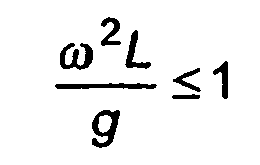
- the rotation rate of the vessel satisfies the relationship: ⁇ 2 ⁇ L g ⁇ 1 where
- particulate material is fed into the vessel to just below 50% of volumetric capacity.
- the particulate material is fed into the vessel to 25% of volumetric capacity.
- the rotatable vessel is tilted at an angle to the horizontal to promote the flow of particulate material through the vessel.
- the rotatable vessel is tilted between 4° and 10° to the horizontal.
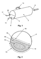
- the device comprises of a rotary longitudinal tube 2 having a fixed end plate 4.
- An input 6 for receiving particulate material to be separated or sorted is located at the opposite end of the tube 2 to end plate 4.
- Fixed end plate 4 functions as an output for the device and has two holes 8, 10 for extracting particles from the tube 2.
- the size and position of holes 8,10 determine the size or density of particles to be extracted at each respective hole.
- the holes or openings 8, 10 in end plate 4 are placed at different radial positions depending on the desired cut-sizes or fractions of particulate material to extract. One or several size fractions can be removed simultaneously.
- Small screw-feeders near holes 8, 10 remove classified particulate material locally around the holes 8, 10 (as shown by arrows 11) and feed the classified streams away to receptacles or next processing stages, as required.
- Other types of extractors may be used instead of the screw-feeders. Should particles of a different size be required, the end plate 4 can be easily replaced with holes of the required size. The number of holes in the end plate 4 may be varied according to requirements.
- Figure 2 illustrates the device and method in operation.
- a "charge" of particle material 12 is placed into tube 2.
- the tube 2 rotates (in the direction of arrow 13)
- the particulate or granular material will first support a slope 18 until the slope 18 exceeds a critical angle. Further rotation past this point initiates an avalanche of material, as indicated by arrow 19 in broken lines.
- This avalanche 19 takes the material in the upper half of the slope 18 and moves it to the lower half of the slope 18.
- particulate material is spread out on the slope 18, causing smaller particles 14 to move or percolate downwards.
- the rate of rotation of the tube 2 determines the rate of separation. If the rotation rate is slow, avalanches 19 are discrete. If the rotation rate is faster then avalanches 19 blend into one another forming a continuous flow. If the rotation rate is faster still, a cascading motion is produced in which particles are lifted off the surface of the charge. Such cascading motion or flow is not favourable to particle separation. Furthermore, if the rotation rate is too fast, centrifugal forces cause the particles to stick to the sides of the tube 2, preventing particle separation.
- the rotation rate, and so the different types of separation, can be measured by the Froude number.
- the avalanching 19 usually occurs at a thin surface layer of the charge 12 of particulate material. While this layer is not uniform, it has been found that the number of particles in the surface layer averages between 5 and 10 particles. In addition, the shape of the surface layer varies according to the rotation rate. For a discrete avalanche regime, the surface layer is triangular in cross section, while for a continuous flow regime the surface layer become more parabolic in cross section with more material towards the middle.
- the device can be tilted at small angles to promote flow through the device. Typical angles of 4°-5° are generally sufficient to allow a suitable flow of material through the device for separation with an upper limit of 10°.
- the optimum filling for a tube with a circular cross-section is 25% capacity or one quarter full as this promotes the most rapid segregation. Fill capacities of up to less than 50% may be used for the device but with lower rates of separation.
- feeder and extractor rates would be tied together to maintain a fill point around the optimum of 25% capacity.
- the classifier equipment could also act as a "buffer" against unexpected material flows from upstream or downstream processing upsets.
- the device When very exacting separation within the fine component is the end goal, the device may be used to remove the coarse component of particulate material rapidly and cheaply. Operated near its optimum fill with very rapid and complete segregation means that the device may be particularly apt for rapid, high-volume, first-pass, coarse segregation.
- Figure 4 shows the results for a charge of particles 20 with a bimodal density distribution.
- the denser particles 22 will collect in the center of the charge 20 and the less dense particles 24 will collect at the boundary of the charge 20.
- radial gradients of density and size difference introduce design criteria for the separating device.
- particles that are both large and dense in a particular ratio tend to mix instead of to separate.
- this mixing zone tends to be small, and in practice many industrial situations classify particles that do not vary greatly in density.
- Figure 6 shows a cross section of a device according to the invention separating building sand according to size. Prior to starting, sand was sifted into four groups of equal masses. The second largest sized group was painted (shown in white). The groups were remixed and poured into the device. Figure 6(a) is the initial condition and 6(e) is after 20 revolutions of the device at 3 rpm. As the sand particle size is distributed over a continuum of values, they are classified with the smallest particles in the centre of the charge and the largest on the boundary of the container with a continuous radial gradation of sized particles.
Landscapes
- Combined Means For Separation Of Solids (AREA)
- Sampling And Sample Adjustment (AREA)
- Processing And Handling Of Plastics And Other Materials For Molding In General (AREA)
Abstract
Description
- The invention relates to a method and device for separating particulate material. In particular, the invention relates to devices for classifying sorting or filtering particulate material.
- The term "particulate material" refers to granular or powdered material such as sand, minerals, rock, gravel, seed and other similar material.
- Sorting or classifying devices are used in a number of industries, such as the construction, recycling and mining industries. These devices are used to separate particulate materials from other undesired substances based on the size of the particulate material. This type of classification is commonly done using screening techniques.
- A known device for sorting particulate material takes the form of a rotary cylindrical screen having holes of predetermined size with a series of rotating single row brushes located within the rotary screen. A screw auger feeds particulate material into the screen and the rotary brushes sweep the particulate material against the screens, causing particles below or at the predetermined size to fall through the holes in the screen and particles larger than the predetermined size to pass along the screen for rejection.
- Document D1 (
SU 1715446 - Sorting devices, including the known device, suffer from one or more of several disadvantages. In some devices, particles approaching the predetermined size can wedge into the holes of the screen. This disrupts the sorting process as well as requiring frequent maintenance of those devices. Many existing sorting devices require screen replacement in order to vary the size of sorting particulate material. Particles hitting the screen in some devices, often at high speed, can cause damage and wear to the screen.
- According to one aspect of the present invention, there is provided a method of separating particulate material (12) of differing size or density, the method including the steps of:
- tumbling the particulate material (12) in a vessel (2) to produce an accumulation radially of particles (16) of selected sizes and extracting particles (14) at selected radial locations, characterised in that the rate of rotation of the vessel (2) is such that a continuous or discrete surface avalanching particulate layer (19) on a bed of particulate material (12) in solid body rotation is produced in which the avalanching particles (19) do not lift off the bed (12) of particulate material to move particles of smaller size (14) or higher density towards the centre of the particulate material (12) and particles of larger size (16) or lower density radially outward from the centre of the particulate material (12).
- According to another aspect of the invention, there is provided a device for separating particulate material (12) of differing size or density, including:
- a rotatable vessel (2) for receiving particulate material (12);
- means (6) for feeding particulate material into the rotatable vessel (2);
- means for rotating the vessel (2) to tumble the particulate material (12) and produce an accumulation radially of particles (14) of selected sizes; and
- means (8,10) for extracting particulate material (14) at selected radial locations, characterised in that the means for rotating the vessel provides a rotation rate of the vessel (2) which satisfies the relationship:

where- ω is the rotation rate;
- L is the diameter of the vessel; and
- g is the acceleration of gravity,
- and the tumbling of the particulate material produces a continuous or discrete surface avalanching particulate layer (19) on a bed of particulate material (12) in solid body rotation in which the avalanching particles (19) do not lift off the bed of particulate material (12) to move particles of smaller size (14) or higher density towards the centre of the particulate material and particles of larger size (16) or lower density radially outward from the centre of the particulate material (12).
- As used in this specification term "avalanche" refers to continuous flow regimes or intermittent (discrete) flow regimes in which falling particles do not lift off the bed of material. Preferably, most of the bed of material is in solid body rotation with a relatively thin layer at the surface avalanching. The thin avalanching layer is not of uniform thickness. For example in the continuous flow regime the thickness of the avalanching layer has a parabolic profile. In accordance with the present invention the average thickness of the avalanching layer in a non-cohesive material is typically about 5 particles and can be up to about 10 particles, although the depth of the avalanching layer depends on preferred rotation speed and, to a lesser extent, on particle properties.
- Tumbling the particulate material to produce avalanches in the particulate material surface promotes the separation of particles according to their size or density. In the case of particles primarily of differing size the smaller particles tend to collect towards the centre of the particulate material while larger particles tend to collect at the boundary of the particulate material. Consequently a radial distribution of particles according to their size is created enabling extraction of particles of selected size by suitably positioned extraction devices. The present invention is not limited to separating materials of differing size that have the same density. Whilst in practice many applications of the invention involve separation of particles of differing size but similar density, differing density of particles can be accommodated. However, when the ratios of particle size to density fulfil a particular and limited relationship, the tumbling action will mix the particles fulfilling that relationship instead of separating those particles, This only occurs for the number of particles obeying the relationship and not all particles in the "charge" of particles in the device. In practice, the number of particles fulfilling this relationship is typically a few percent of the entire charge of particles.
- In the case of separating particulate material primarily of differing densities, tumbling the material to produce avalanches promotes the separation of the material according to its densities. More dense particles tend to collect toward the centre of the particulate materials whilst less dense particles tend to collect at the boundary of the particulate material. Again this provides for separation by collection at a suitable radial location. Separation according to density has a number of applications including for example in the recycling industry to separate a mixture of insulation and copper wire. Thus, the present invention allows particles to be extracted according to their size or density without the difficulties associated with known devices. For example, the invention does not employ a screen to sort the particulate material. This means that there is no risk of particles wedging into the screen and disrupting the sorting process. In addition, particles can be selected according to their size easily and conveniently by sampling the particulate material along its radius for the required size.
- The method and device according to the invention provides for low energy consumption and does not require as much space as for known sorters using conventional screens. Furthermore, the device according to the invention has a large turn down ratio, allowing the device to be shut down and restarted with ease.
- The method provides for less wear on both the particles and the device. Particles are separated under rotation and gravity and so the particles do not strike equipment at high speed. Particles tend to erode through inter-particle contact and not by contact with the device.
- It is preferred that tumbling the particulate material produces a continuous or intermittent flow of particles along the surface. Particles are preferably extracted at radial locations outward from the centre of the particulate material.
- The rotating means preferably tumbles the particulate material to produce a continuous or intermittent flow of particulate material along the surface. Preferably, the extracting means is located such that it extracts particulate material at radial locations outward from the centre of the particulate material.
- Preferably, the extracting means is located adjacent to the rotatable vessel so that particles may be extracted along a radius of the particulate material. The extracting means may be in the form of a plate with one or more holes radially located relative to the particulate material. The extracting means may have feeders near the holes for promoting the extraction of particles. In other forms of the invention the extracting means may include one or more augers or pneumatic suction lines.
- Preferably, the rotation rate of the vessel satisfies the relationship:
where - ω is the rotation rate;
- L is the diameter of the vessel; and
- g is the acceleration of gravity.
- It is preferred that particulate material is fed into the vessel to just below 50% of volumetric capacity. Preferably, the particulate material is fed into the vessel to 25% of volumetric capacity.
- It is preferred that the rotatable vessel is tilted at an angle to the horizontal to promote the flow of particulate material through the vessel. Preferably, the rotatable vessel is tilted between 4° and 10° to the horizontal.
- To assist in the understanding of the invention, a preferred embodiment of the invention will now be described by way of example only, with reference to the drawings, of which:
-
Figure 1 is a perspective view of a device for separating particulate material according to a preferred embodiment of the invention; -
Figure 2 is a sectional view of the device ofFigure 1 illustrating the method of separating particulate material; -
Figure 3 is an illustration of the principles of the method of separating particulate material as applied by the device ofFigure 1 . -
Figure 4 illustrates the method when applied to separating particles according to density; -
Figure 5 shows schematically the particular relationship between particle size and density for which mixing occurs; and -
Figures 6(a) to 6(e) show the separation of building sand according to size by the device ofFigure 1 . - Referring to
Figure 1 , there is shown a device for separating particulate material in accordance with a preferred embodiment of the invention. The device comprises of a rotarylongitudinal tube 2 having afixed end plate 4. - An
input 6 for receiving particulate material to be separated or sorted is located at the opposite end of thetube 2 to endplate 4.Fixed end plate 4 functions as an output for the device and has twoholes tube 2. The size and position ofholes openings end plate 4 are placed at different radial positions depending on the desired cut-sizes or fractions of particulate material to extract. One or several size fractions can be removed simultaneously. Small screw-feeders (not shown) nearholes holes 8, 10 (as shown by arrows 11) and feed the classified streams away to receptacles or next processing stages, as required. Other types of extractors may be used instead of the screw-feeders. Should particles of a different size be required, theend plate 4 can be easily replaced with holes of the required size. The number of holes in theend plate 4 may be varied according to requirements. -
Figure 2 illustrates the device and method in operation. A "charge" ofparticle material 12 is placed intotube 2. As thetube 2 rotates (in the direction of arrow 13), the particulate or granular material will first support aslope 18 until theslope 18 exceeds a critical angle. Further rotation past this point initiates an avalanche of material, as indicated byarrow 19 in broken lines. Thisavalanche 19 takes the material in the upper half of theslope 18 and moves it to the lower half of theslope 18. During theavalanche 19, particulate material is spread out on theslope 18, causingsmaller particles 14 to move or percolate downwards. Ascharge 12 is rotating as a solid body, the action of theavalanche 19 on theparticles smaller size 14 to move towards the centre of thecharge 12, instead of the bottom ofcharge 12. Similarly, particles oflarger size 16 move towards the boundary ofcharge 12. Repeated avalanching rapidly segregates theentire charge 12 by size as shown inFigure 2 . If the particle size is distributed over a continuum of values, then the sizes are segregated with thesmallest particles 14 in the centre of thecharge 12 and thelargest particles 16 on the boundary of thetube 2 with a continuous radial gradation of sized particles. - The physical mechanism for the size segregation is described in more detail with reference to
Figure 3 . When stationary, granules or particles interlock in groups. During theavalanche 19, the moving groups of particles dilate, i.e. they move farther apart from each other. This dilation increases the average spacing between particles that in turn allowssmaller particles 14 to percolate downwards under the influence of gravity. When not spherical, as drawn,large particles 16 can also be rotated up to the surface by the differential velocities in the avalanching layer. Consequently, repeated avalanches promote the separation ofparticles 14 andlarger particles 16. - It can be seen that the rate of rotation of the
tube 2 determines the rate of separation. If the rotation rate is slow,avalanches 19 are discrete. If the rotation rate is faster thenavalanches 19 blend into one another forming a continuous flow. If the rotation rate is faster still, a cascading motion is produced in which particles are lifted off the surface of the charge. Such cascading motion or flow is not favourable to particle separation. Furthermore, if the rotation rate is too fast, centrifugal forces cause the particles to stick to the sides of thetube 2, preventing particle separation. - The rotation rate, and so the different types of separation, can be measured by the Froude number. The Froude number is defined by the following equation:

where - Fr is the Froude number;
- w is the angular velocity or rotation rate;
- L is the tube diameter or radius; and
- g is the acceleration of gravity.
- A Froude number in the range of Fr < 10-3 to 10-2 means that the rotation rate w produces discrete avalanches. Generally, a transition from avalanching to continuous flow occurs over the
range 10-3 < Fr < 10-2. A continuous flow regime is produced for Froude numbers up to Fr = 10-1. Froude numbers in the range of 10-1 < Fr < 1 means that the rotation rate w generates a cascading motion of particulate material. Rotation rates of Fr > 1 produce centrifugal motion and particulate material ceases to separate. - The avalanching 19 usually occurs at a thin surface layer of the
charge 12 of particulate material. While this layer is not uniform, it has been found that the number of particles in the surface layer averages between 5 and 10 particles. In addition, the shape of the surface layer varies according to the rotation rate. For a discrete avalanche regime, the surface layer is triangular in cross section, while for a continuous flow regime the surface layer become more parabolic in cross section with more material towards the middle. - It has been estimated that there are approximately 30 avalanches during one revolution of the
tube 2 at 5 rpm. It has also been found that 5 revolutions oftube 2 at 3 rpm is sufficient to achieve full separation of particulate material at 25% capacity. - The device can be tilted at small angles to promote flow through the device. Typical angles of 4°-5° are generally sufficient to allow a suitable flow of material through the device for separation with an upper limit of 10°.
- The optimum filling for a tube with a circular cross-section is 25% capacity or one quarter full as this promotes the most rapid segregation. Fill capacities of up to less than 50% may be used for the device but with lower rates of separation.
- In a continuous operation, feeder and extractor rates would be tied together to maintain a fill point around the optimum of 25% capacity. However, it may also be desirable to allow wide variations from the optimum as this would mean the classifier equipment could also act as a "buffer" against unexpected material flows from upstream or downstream processing upsets.
- When very exacting separation within the fine component is the end goal, the device may be used to remove the coarse component of particulate material rapidly and cheaply. Operated near its optimum fill with very rapid and complete segregation means that the device may be particularly apt for rapid, high-volume, first-pass, coarse segregation.
- It has also been found that classification by density of particle gives a similar result, though from a somewhat different mechanism.
Figure 4 shows the results for a charge ofparticles 20 with a bimodal density distribution. Thedenser particles 22 will collect in the center of thecharge 20 and the lessdense particles 24 will collect at the boundary of thecharge 20. - In some applications radial gradients of density and size difference introduce design criteria for the separating device. As exemplified by
Figure 5 , particles that are both large and dense in a particular ratio tend to mix instead of to separate. However, this mixing zone tends to be small, and in practice many industrial situations classify particles that do not vary greatly in density. - So far the preferred embodiments discussed have used particles with bimodal distribution of size or density. However, the device is not restricted in any way by property distributions.
Figure 6 shows a cross section of a device according to the invention separating building sand according to size. Prior to starting, sand was sifted into four groups of equal masses. The second largest sized group was painted (shown in white). The groups were remixed and poured into the device.Figure 6(a) is the initial condition and 6(e) is after 20 revolutions of the device at 3 rpm. As the sand particle size is distributed over a continuum of values, they are classified with the smallest particles in the centre of the charge and the largest on the boundary of the container with a continuous radial gradation of sized particles. - An experiment was performed using the same device with the particulate material being salt. In this test the larger half of the salt size distribution had been dyed green. Classification was complete in the device after 3 revolutions at 2 rpm.
- The foregoing describes only one embodiment of the invention and modifications can be made without departing from the scope of the invention as defined in the claims.
Claims (16)
- A method of separating particulate material (12) of differing size or density, the method including the steps of:tumbling the particulate material (12) in a vessel (2) to produce an accumulation radially of particles (16) of selected sizes and extracting particles (14) at selected radial locations, characterised in that the rate of rotation of the vessel (2) is such that a continuous or discrete surface avalanching particulate layer (19) on a bed of particulate material (12) in solid body rotation is produced in which the avalanching particles (19) do not lift off the bed (12) of particulate material to move particles of smaller size (14) or higher density towards the centre of the particulate material (12) and particles of larger size (16) or lower density radially outward from the centre of the particulate material (12).
- The method of claim 1, wherein said tumbling produces a continuous or intermittent flow of particles (12) along the bed of particulate material.
- The method of claim 1, wherein particles (14) are extracted at radial locations outward from the centre of the particulate material (12).
- The method of any one of claims 1 to 3, wherein the rotation rate of the vessel (2) satisfies the relationship:

whereω is the rotation rate;L is the diameter of the vessel; andg is the acceleration of gravity - The method of any one of claims 1 to 4, further comprising tilting the vessel (2) at an angle to the horizontal to promote flow of the particulate material (12) through the vessel (2).
- The method of any one of claims 1 to 5, wherein the particulate material (12) is fed into the vessel up to just below 50% of volumetric capacity.
- A device for separating particulate material (12) of differing size or density, including:a rotatable vessel (2) for receiving particulate material (12);means (6) for feeding particulate material into the rotatable vessel (2);means for rotating the vessel (2) to tumble the particulate material (12) and produce an accumulation radially of particles (14) of selected sizes; andmeans (8,10) for extracting particulate material (14) at selected radial locations, characterised in that the means for rotating the vessel provides a rotation rate of the vessel (2) which satisfies the relationship:

wherew is the rotation rate;L is the diameter of the vessel; andg is the acceleration of gravity,and the tumbling of the particulate material produces a continuous or discrete surface avalanching particulate layer (19) on a bed of particulate material (12) in solid body rotation in which the avalanching particles (19) do not lift off the bed of particulate material (12) to move particles of smaller size (14) or higher density towards the centre of the particulate material and particles of larger size (16) or lower density radially outward from the centre of the particulate material (12). - The device of claim 7, wherein the rotating means tumbles the particulate material to produce a continuous or intermittent flow of particulate material (12) along the bed of particulate material.
- The device of claim 7 or claim 8, wherein the rotatable vessel (2) is tilted at an angle to the horizontal to promote the flow of particulate material (12) through the vessel (2).
- The device of claim 9, wherein the rotatable vessel (12) is tilted between 4° and 10° to the horizontal.
- The device of any one of claims 7 to 10, wherein the extracting means (8,10) extracts particulate material at radial locations outward from the centre of the particulate material (12).
- The device of claim 11, wherein the extracting means (8,10) is located adjacent to the rotatable vessel.
- The device of claim 12, wherein the extracting means includes a plate (4) with one or more holes (8,10) radially located relative to the particulate material.
- The device of claim 12, wherein the extracting means includes one or more augers or pneumatic suction lines.
- The device of any one of claims 7 to 14, wherein the means for feeding particulate material (12) feeds the particulate material (12) into the vessel up to just below 50% of the volumetric capacity.
- The device of claim 15, wherein the means for feeding particulate material (12) feeds the particulate material (12) into the vessel to 25% of volumetric capacity.
Applications Claiming Priority (3)
| Application Number | Priority Date | Filing Date | Title |
|---|---|---|---|
| AUPP675501 | 2001-08-01 | ||
| AUPR6755A AUPR675501A0 (en) | 2001-08-01 | 2001-08-01 | A method and device for separating particulate material |
| PCT/AU2002/001025 WO2003011483A1 (en) | 2001-08-01 | 2002-08-01 | A method and device for separating particulate material |
Publications (3)
| Publication Number | Publication Date |
|---|---|
| EP1412103A1 EP1412103A1 (en) | 2004-04-28 |
| EP1412103A4 EP1412103A4 (en) | 2004-10-13 |
| EP1412103B1 true EP1412103B1 (en) | 2010-01-06 |
Family
ID=3830711
Family Applications (1)
| Application Number | Title | Priority Date | Filing Date |
|---|---|---|---|
| EP02750658A Expired - Lifetime EP1412103B1 (en) | 2001-08-01 | 2002-08-01 | A method and device for separating particulate material |
Country Status (8)
| Country | Link |
|---|---|
| US (1) | US7448500B2 (en) |
| EP (1) | EP1412103B1 (en) |
| CN (1) | CN1260016C (en) |
| AT (1) | ATE454224T1 (en) |
| AU (2) | AUPR675501A0 (en) |
| NZ (1) | NZ530680A (en) |
| WO (1) | WO2003011483A1 (en) |
| ZA (1) | ZA200400578B (en) |
Families Citing this family (10)
| Publication number | Priority date | Publication date | Assignee | Title |
|---|---|---|---|---|
| US20070076706A1 (en) * | 2005-09-30 | 2007-04-05 | Siemens Aktiengesellschaft | Fast reroute in a multiprotocol label switching network |
| US8075785B2 (en) * | 2009-05-22 | 2011-12-13 | Omni Energy Services Corp. | Separation vessel for solids removal |
| US9126233B2 (en) | 2009-11-27 | 2015-09-08 | Arrowcorp Inc. | Cylinder exchange device and method for solid material processor |
| DE102010045309A1 (en) * | 2010-09-14 | 2012-03-15 | Dirk Barnstedt | Process for separating sheet-like and body-shaped solids in a stream of bulk material |
| US9663843B2 (en) | 2010-12-02 | 2017-05-30 | The University Of Birmingham | Magnet recycling |
| GB2486175A (en) * | 2010-12-02 | 2012-06-13 | Univ Birmingham | Separating rare earth magnetic materials from electronic devices |
| CN103827445A (en) * | 2011-07-08 | 2014-05-28 | 技术信息有限公司 | Sorting in mining operation |
| CN102415243B (en) * | 2011-10-04 | 2013-10-30 | 吉林大学 | Discrete-element-method-based corn threshing process analysis method |
| CA172569S (en) | 2017-01-16 | 2018-02-08 | Arrowcorp Inc | Grading cylinder |
| CA3248912A1 (en) | 2022-02-21 | 2023-08-24 | Artem PEREKRESNYI | Apparatus for dry granular mixtures separation |
Family Cites Families (8)
| Publication number | Priority date | Publication date | Assignee | Title |
|---|---|---|---|---|
| US327707A (en) * | 1885-10-06 | moffitt | ||
| US2872300A (en) * | 1954-10-18 | 1959-02-03 | Phillips Petroleum Co | Process and apparatus for simultaneously pelleting powdered materials and classifying same |
| US3804249A (en) * | 1972-10-30 | 1974-04-16 | Gen Electric | Air drum sorter for solid waste |
| US4070202A (en) * | 1976-03-24 | 1978-01-24 | Cargill, Incorporated | Method and apparatus for separating solid materials |
| SU1458031A1 (en) * | 1987-02-24 | 1989-02-15 | Камский политехнический институт | Apparatus for separating loose materials |
| SU1632520A1 (en) * | 1988-07-05 | 1991-03-07 | Камский политехнический институт | Method for separating bulk materials |
| SU1715446A1 (en) * | 1989-10-30 | 1992-02-28 | Камский политехнический институт | Device for separating loose materials according to size of their particles |
| DE4416756A1 (en) * | 1994-05-13 | 1995-11-16 | Koch Transporttechnik Gmbh | Rotary separator for classification of refuse into various sizes |
-
2001
- 2001-08-01 AU AUPR6755A patent/AUPR675501A0/en not_active Abandoned
-
2002
- 2002-08-01 CN CNB028167317A patent/CN1260016C/en not_active Expired - Fee Related
- 2002-08-01 NZ NZ530680A patent/NZ530680A/en not_active IP Right Cessation
- 2002-08-01 AT AT02750658T patent/ATE454224T1/en not_active IP Right Cessation
- 2002-08-01 AU AU2002355613A patent/AU2002355613C1/en not_active Ceased
- 2002-08-01 US US10/484,968 patent/US7448500B2/en not_active Expired - Fee Related
- 2002-08-01 EP EP02750658A patent/EP1412103B1/en not_active Expired - Lifetime
- 2002-08-01 WO PCT/AU2002/001025 patent/WO2003011483A1/en not_active Ceased
-
2004
- 2004-01-26 ZA ZA200400578A patent/ZA200400578B/en unknown
Also Published As
| Publication number | Publication date |
|---|---|
| WO2003011483A1 (en) | 2003-02-13 |
| ZA200400578B (en) | 2004-10-25 |
| AU2002355613B2 (en) | 2008-06-26 |
| US7448500B2 (en) | 2008-11-11 |
| CN1260016C (en) | 2006-06-21 |
| ATE454224T1 (en) | 2010-01-15 |
| NZ530680A (en) | 2006-04-28 |
| AUPR675501A0 (en) | 2001-08-23 |
| AU2002355613C1 (en) | 2009-01-08 |
| US20040251181A1 (en) | 2004-12-16 |
| EP1412103A4 (en) | 2004-10-13 |
| EP1412103A1 (en) | 2004-04-28 |
| CN1547514A (en) | 2004-11-17 |
Similar Documents
| Publication | Publication Date | Title |
|---|---|---|
| Shapiro et al. | Air classification of solid particles: a review | |
| DE69418785T2 (en) | Sorting device for non-ferrous materials | |
| JP5735925B2 (en) | Selective particle size separation device for hard powdered material by centrifugal action and method of using such device | |
| US20060266676A1 (en) | Rotary Aggregate Washing and Classification System | |
| US7448500B2 (en) | Method and device for separating particulate material | |
| US4921173A (en) | Methods of mineral breaking and apparatus used therefor | |
| AU2002355613A1 (en) | A method and device for separating particulate material | |
| US4148725A (en) | Process and apparatus for separating particles by relative density | |
| CN109290045A (en) | A device and method for pulping using gold tailings waste residue | |
| DE3626044C2 (en) | ||
| US4206046A (en) | Process and apparatus for separating particles by relative density | |
| KR102132932B1 (en) | Wind force soil sorting apparatus | |
| KR101576989B1 (en) | mixture particle separating system | |
| US4582202A (en) | Centrifugal sorting method | |
| EP3352917B1 (en) | Cement grinding media sorter and operating method thereof | |
| RU2170626C1 (en) | Centrifugal classifier | |
| RU2318612C1 (en) | Separator | |
| WO1986000031A1 (en) | A method and apparatus for separating metal particles | |
| DE102018115480B4 (en) | Wind sifter and wind sifter | |
| RU2213631C1 (en) | Apparatus for screening solid domestic waste materials | |
| KR102707520B1 (en) | Magnetic sorter | |
| KR0130339Y1 (en) | Powder classifier using wind power and specific gravity | |
| CN219560357U (en) | Sorting turntable for sorting equipment | |
| US4311585A (en) | Classification of particulate material | |
| AU8421398A (en) | Sorting apparatus |
Legal Events
| Date | Code | Title | Description |
|---|---|---|---|
| PUAI | Public reference made under article 153(3) epc to a published international application that has entered the european phase |
Free format text: ORIGINAL CODE: 0009012 |
|
| 17P | Request for examination filed |
Effective date: 20040128 |
|
| AK | Designated contracting states |
Kind code of ref document: A1 Designated state(s): AT BE BG CH CY CZ DE DK EE ES FI FR GB GR IE IT LI LU MC NL PT SE SK TR |
|
| AX | Request for extension of the european patent |
Extension state: AL LT LV MK RO SI |
|
| A4 | Supplementary search report drawn up and despatched |
Effective date: 20040830 |
|
| GRAP | Despatch of communication of intention to grant a patent |
Free format text: ORIGINAL CODE: EPIDOSNIGR1 |
|
| GRAS | Grant fee paid |
Free format text: ORIGINAL CODE: EPIDOSNIGR3 |
|
| GRAA | (expected) grant |
Free format text: ORIGINAL CODE: 0009210 |
|
| AK | Designated contracting states |
Kind code of ref document: B1 Designated state(s): AT BE BG CH CY CZ DE DK EE ES FI FR GB GR IE IT LI LU MC NL PT SE SK TR |
|
| REG | Reference to a national code |
Ref country code: GB Ref legal event code: FG4D |
|
| REG | Reference to a national code |
Ref country code: CH Ref legal event code: EP |
|
| REG | Reference to a national code |
Ref country code: IE Ref legal event code: FG4D |
|
| REF | Corresponds to: |
Ref document number: 60235016 Country of ref document: DE Date of ref document: 20100225 Kind code of ref document: P |
|
| REG | Reference to a national code |
Ref country code: NL Ref legal event code: VDEP Effective date: 20100106 |
|
| PG25 | Lapsed in a contracting state [announced via postgrant information from national office to epo] |
Ref country code: AT Free format text: LAPSE BECAUSE OF FAILURE TO SUBMIT A TRANSLATION OF THE DESCRIPTION OR TO PAY THE FEE WITHIN THE PRESCRIBED TIME-LIMIT Effective date: 20100106 |
|
| PG25 | Lapsed in a contracting state [announced via postgrant information from national office to epo] |
Ref country code: NL Free format text: LAPSE BECAUSE OF FAILURE TO SUBMIT A TRANSLATION OF THE DESCRIPTION OR TO PAY THE FEE WITHIN THE PRESCRIBED TIME-LIMIT Effective date: 20100106 Ref country code: PT Free format text: LAPSE BECAUSE OF FAILURE TO SUBMIT A TRANSLATION OF THE DESCRIPTION OR TO PAY THE FEE WITHIN THE PRESCRIBED TIME-LIMIT Effective date: 20100506 Ref country code: ES Free format text: LAPSE BECAUSE OF FAILURE TO SUBMIT A TRANSLATION OF THE DESCRIPTION OR TO PAY THE FEE WITHIN THE PRESCRIBED TIME-LIMIT Effective date: 20100417 |
|
| PG25 | Lapsed in a contracting state [announced via postgrant information from national office to epo] |
Ref country code: FI Free format text: LAPSE BECAUSE OF FAILURE TO SUBMIT A TRANSLATION OF THE DESCRIPTION OR TO PAY THE FEE WITHIN THE PRESCRIBED TIME-LIMIT Effective date: 20100106 |
|
| PG25 | Lapsed in a contracting state [announced via postgrant information from national office to epo] |
Ref country code: BE Free format text: LAPSE BECAUSE OF FAILURE TO SUBMIT A TRANSLATION OF THE DESCRIPTION OR TO PAY THE FEE WITHIN THE PRESCRIBED TIME-LIMIT Effective date: 20100106 Ref country code: SE Free format text: LAPSE BECAUSE OF FAILURE TO SUBMIT A TRANSLATION OF THE DESCRIPTION OR TO PAY THE FEE WITHIN THE PRESCRIBED TIME-LIMIT Effective date: 20100106 Ref country code: CY Free format text: LAPSE BECAUSE OF FAILURE TO SUBMIT A TRANSLATION OF THE DESCRIPTION OR TO PAY THE FEE WITHIN THE PRESCRIBED TIME-LIMIT Effective date: 20100106 Ref country code: EE Free format text: LAPSE BECAUSE OF FAILURE TO SUBMIT A TRANSLATION OF THE DESCRIPTION OR TO PAY THE FEE WITHIN THE PRESCRIBED TIME-LIMIT Effective date: 20100106 Ref country code: GR Free format text: LAPSE BECAUSE OF FAILURE TO SUBMIT A TRANSLATION OF THE DESCRIPTION OR TO PAY THE FEE WITHIN THE PRESCRIBED TIME-LIMIT Effective date: 20100407 |
|
| PLBE | No opposition filed within time limit |
Free format text: ORIGINAL CODE: 0009261 |
|
| STAA | Information on the status of an ep patent application or granted ep patent |
Free format text: STATUS: NO OPPOSITION FILED WITHIN TIME LIMIT |
|
| PG25 | Lapsed in a contracting state [announced via postgrant information from national office to epo] |
Ref country code: BG Free format text: LAPSE BECAUSE OF FAILURE TO SUBMIT A TRANSLATION OF THE DESCRIPTION OR TO PAY THE FEE WITHIN THE PRESCRIBED TIME-LIMIT Effective date: 20100406 Ref country code: SK Free format text: LAPSE BECAUSE OF FAILURE TO SUBMIT A TRANSLATION OF THE DESCRIPTION OR TO PAY THE FEE WITHIN THE PRESCRIBED TIME-LIMIT Effective date: 20100106 Ref country code: CZ Free format text: LAPSE BECAUSE OF FAILURE TO SUBMIT A TRANSLATION OF THE DESCRIPTION OR TO PAY THE FEE WITHIN THE PRESCRIBED TIME-LIMIT Effective date: 20100106 |
|
| 26N | No opposition filed |
Effective date: 20101007 |
|
| PG25 | Lapsed in a contracting state [announced via postgrant information from national office to epo] |
Ref country code: DK Free format text: LAPSE BECAUSE OF FAILURE TO SUBMIT A TRANSLATION OF THE DESCRIPTION OR TO PAY THE FEE WITHIN THE PRESCRIBED TIME-LIMIT Effective date: 20100106 |
|
| PG25 | Lapsed in a contracting state [announced via postgrant information from national office to epo] |
Ref country code: IT Free format text: LAPSE BECAUSE OF FAILURE TO SUBMIT A TRANSLATION OF THE DESCRIPTION OR TO PAY THE FEE WITHIN THE PRESCRIBED TIME-LIMIT Effective date: 20100106 Ref country code: MC Free format text: LAPSE BECAUSE OF NON-PAYMENT OF DUE FEES Effective date: 20100831 |
|
| REG | Reference to a national code |
Ref country code: CH Ref legal event code: PL |
|
| GBPC | Gb: european patent ceased through non-payment of renewal fee |
Effective date: 20100801 |
|
| PG25 | Lapsed in a contracting state [announced via postgrant information from national office to epo] |
Ref country code: LI Free format text: LAPSE BECAUSE OF NON-PAYMENT OF DUE FEES Effective date: 20100831 Ref country code: CH Free format text: LAPSE BECAUSE OF NON-PAYMENT OF DUE FEES Effective date: 20100831 |
|
| REG | Reference to a national code |
Ref country code: FR Ref legal event code: ST Effective date: 20110502 |
|
| REG | Reference to a national code |
Ref country code: DE Ref legal event code: R119 Ref document number: 60235016 Country of ref document: DE Effective date: 20110301 |
|
| PG25 | Lapsed in a contracting state [announced via postgrant information from national office to epo] |
Ref country code: IE Free format text: LAPSE BECAUSE OF NON-PAYMENT OF DUE FEES Effective date: 20100801 Ref country code: FR Free format text: LAPSE BECAUSE OF NON-PAYMENT OF DUE FEES Effective date: 20100831 Ref country code: DE Free format text: LAPSE BECAUSE OF NON-PAYMENT OF DUE FEES Effective date: 20110301 |
|
| PG25 | Lapsed in a contracting state [announced via postgrant information from national office to epo] |
Ref country code: GB Free format text: LAPSE BECAUSE OF NON-PAYMENT OF DUE FEES Effective date: 20100801 |
|
| PG25 | Lapsed in a contracting state [announced via postgrant information from national office to epo] |
Ref country code: LU Free format text: LAPSE BECAUSE OF NON-PAYMENT OF DUE FEES Effective date: 20100801 |
|
| PG25 | Lapsed in a contracting state [announced via postgrant information from national office to epo] |
Ref country code: TR Free format text: LAPSE BECAUSE OF FAILURE TO SUBMIT A TRANSLATION OF THE DESCRIPTION OR TO PAY THE FEE WITHIN THE PRESCRIBED TIME-LIMIT Effective date: 20100106 |