EP1411749A2 - Dehumidifying device for hearing aids - Google Patents
Dehumidifying device for hearing aids Download PDFInfo
- Publication number
- EP1411749A2 EP1411749A2 EP03380186A EP03380186A EP1411749A2 EP 1411749 A2 EP1411749 A2 EP 1411749A2 EP 03380186 A EP03380186 A EP 03380186A EP 03380186 A EP03380186 A EP 03380186A EP 1411749 A2 EP1411749 A2 EP 1411749A2
- Authority
- EP
- European Patent Office
- Prior art keywords
- damp
- bodies
- cavity
- accumulation
- hearing aids
- Prior art date
- Legal status (The legal status is an assumption and is not a legal conclusion. Google has not performed a legal analysis and makes no representation as to the accuracy of the status listed.)
- Withdrawn
Links
Images
Classifications
-
- F—MECHANICAL ENGINEERING; LIGHTING; HEATING; WEAPONS; BLASTING
- F26—DRYING
- F26B—DRYING SOLID MATERIALS OR OBJECTS BY REMOVING LIQUID THEREFROM
- F26B9/00—Machines or apparatus for drying solid materials or objects at rest or with only local agitation; Domestic airing cupboards
- F26B9/003—Small self-contained devices, e.g. portable
-
- H—ELECTRICITY
- H04—ELECTRIC COMMUNICATION TECHNIQUE
- H04R—LOUDSPEAKERS, MICROPHONES, GRAMOPHONE PICK-UPS OR LIKE ACOUSTIC ELECTROMECHANICAL TRANSDUCERS; ELECTRIC HEARING AIDS; PUBLIC ADDRESS SYSTEMS
- H04R25/00—Electric hearing aids
-
- H—ELECTRICITY
- H04—ELECTRIC COMMUNICATION TECHNIQUE
- H04R—LOUDSPEAKERS, MICROPHONES, GRAMOPHONE PICK-UPS OR LIKE ACOUSTIC ELECTROMECHANICAL TRANSDUCERS; ELECTRIC HEARING AIDS; PUBLIC ADDRESS SYSTEMS
- H04R2460/00—Details of hearing devices, i.e. of ear- or headphones covered by H04R1/10 or H04R5/033 but not provided for in any of their subgroups, or of hearing aids covered by H04R25/00 but not provided for in any of its subgroups
- H04R2460/17—Hearing device specific tools used for storing or handling hearing devices or parts thereof, e.g. placement in the ear, replacement of cerumen barriers, repair, cleaning hearing devices
Definitions
- This invention is a dehumidifying device for hearing aids and similar apparatuses, contributing essential new features that offer marked advantages when compared to the methods familiarly employed for the same purposes in this technical field today.
- the invention sets out to develop a device that provides a housing for hearing aids, or similar apparatuses, in which optimum temperature conditions are maintained so as to eliminate any damp that might possibly come to affect them, thus ensuring that these apparatuses are kept under the best operational conditions for the user.
- the device which is basically built in a box form, incorporates an electrical heating system, either to be directly fed from the mains supply or for use with any other energy source, whilst it also incorporates means for the regulation of the temperature, in order to keep it at whatever level is considered to be the most suitable for the particular kind of device that is being used.
- the field of application covered by this invention falls within the industrial sector, in areas generally dedicated to the manufacture of devices and methods for maintaining and storing orthopaedic and similar material.
- the fundamental objective of this invention is to provide effective answers to solve the problematic that has been described.
- the objective has been successfully addressed by means of the device described below. It consists of a box-shaped housing designed to contain the hearing aid and keep it under temperature conditions that will prevent the accumulation and/or condensation of damp, whilst, at the same time, the temperature is maintained below a threshold level that is predetermined to ensure that the electronic circuits built into the apparatus cannot be adversely affected.
- the housing for the apparatus which, as has been said, is box-shaped, includes a cavity within which the apparatus is placed.
- the base of the cavity has multiple perforations, thus creating holes for the hot air to pass through, while underneath the base there is provision for the incorporation of heating elements, which generally consist of a set of electrical resistors that can be fed with alternating current through connection to the mains via a suitable cable, while, in alternative versions, the resistors could be supplied with continuous current, via batteries, a power supply, solar cells, or any other device equipped to provide the power necessary to generate the right amount of heat to maintain the apparatus at a temperature guaranteed to keep it damp free.
- the unit also incorporates a system to control the temperature and maintain it at the right level, within predetermined limits, for which purpose provision has been made for some kind of mechanical, electrical, electronic or I.T.-based sensor, such as a thermostat or similar device, as well as the optional installation of a small ventilator that could be activated in the event of the temperature surpassing the predetermined threshold level.
- a system to control the temperature and maintain it at the right level, within predetermined limits, for which purpose provision has been made for some kind of mechanical, electrical, electronic or I.T.-based sensor, such as a thermostat or similar device, as well as the optional installation of a small ventilator that could be activated in the event of the temperature surpassing the predetermined threshold level.
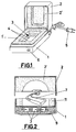
- FIG. 1 we observe a perspective representation of a box which, as a unit, constitutes the material invention, and is preferably built from malleable material, e.g. suitable plastic material, lined inside with heat-insulating material designed to guarantee that the temperature within is kept at the desired level.
- the box is made up of a lower body 1 and an upper body 2 or lid, both of which are hinged together along one of their edges, as is customary.
- the inside lining, in relation to each of the aforementioned bodies, is indicated in the diagram using references 1' and 2', respectively, and is configured in such a way that, in regard to the lower body 1, at least, a central cavity 3 has been formed, affecting a substantial area of the surface, delimited below by a base wall in which a large number of through holes 4 have been bored.
- the heat-generating elements for reaching the working temperature desired are housed, in addition to the sensor and temperature control elements mentioned above.
- the unit is complemented by a cable and plug 5 for connection to the electrical network or other power source, as well as a pilot 6, which indicates whether the device is connected or disconnected, according to whether it is turned on or off, and which in this diagram is located on the front wall of the lower body 1 of the box, but which, logically, might be located in any other suitable position.
- the peripheral lid wall of body 2 has been projected along the perimeter so that it can be attached to the corresponding part of the lower body 1. In this way an appropriate hermetic fit between both bodies is guaranteed, the aim being to keep the internal temperature constantly at the desired level.
Landscapes
- Engineering & Computer Science (AREA)
- Acoustics & Sound (AREA)
- Neurosurgery (AREA)
- Otolaryngology (AREA)
- Physics & Mathematics (AREA)
- General Health & Medical Sciences (AREA)
- Health & Medical Sciences (AREA)
- Signal Processing (AREA)
- Mechanical Engineering (AREA)
- General Engineering & Computer Science (AREA)
- Drying Of Gases (AREA)
- Catching Or Destruction (AREA)
- Solid-Sorbent Or Filter-Aiding Compositions (AREA)
Abstract
Description
Claims (1)
- Dehumidifying device for hearing aids or similar apparatuses, for their maintenance in damp and condensation free conditions and in avoidance of the risks deriving from such accumulation, being characterised by the box shape it adopts in its preferred form of implementation, consisting essentially of a lower body (1) and an upper body (2), the former joined in a hinged manner to the upper body in lid form, both bodies (1, 2) lined inside with heat-insulating material (1' , 2'), so that at least one of the bodies, preferably the lower body (1), has formed a cavity (3) designed to house the apparatus (7), this cavity delimited in its lower part by a base wall in which a multiplicity of thoroughfare holes (4) have been bored, under whose base the device has a set of heating elements incorporated, consisting of a group of resistors (8) fed electrically from the mains or any other appropriate power source, joined to components acting as sensors and to control the heat generated, the purpose being to keep the inside temperature at a level that is sufficient to prevent the accumulation of damp in the apparatus under protection, whilst it remains at the same time below a predetermined threshold to prevent possible damage to the electronic devices built into the hearing aid.
Applications Claiming Priority (2)
| Application Number | Priority Date | Filing Date | Title |
|---|---|---|---|
| ES200202479U ES1053160Y (en) | 2002-10-16 | 2002-10-16 | DEHUMIFIER DEVICE FOR AUDIOPROTESICAL DEVICES. |
| ES200202479U | 2002-10-16 |
Publications (2)
| Publication Number | Publication Date |
|---|---|
| EP1411749A2 true EP1411749A2 (en) | 2004-04-21 |
| EP1411749A3 EP1411749A3 (en) | 2004-05-19 |
Family
ID=8502300
Family Applications (1)
| Application Number | Title | Priority Date | Filing Date |
|---|---|---|---|
| EP03380186A Withdrawn EP1411749A3 (en) | 2002-10-16 | 2003-08-01 | Dehumidifying device for hearing aids |
Country Status (2)
| Country | Link |
|---|---|
| EP (1) | EP1411749A3 (en) |
| ES (1) | ES1053160Y (en) |
Cited By (6)
| Publication number | Priority date | Publication date | Assignee | Title |
|---|---|---|---|---|
| DE202005002431U1 (en) * | 2005-02-14 | 2005-04-21 | Büschken, Hermann, Dr.med. | Portable Bags e.g. handbag, for accommodating hearing aid, has storage container configured to keep hearing aid in inner room where articles are stored, and equipped with cover to wrap hearing aid |
| EP1867245A1 (en) * | 2006-06-14 | 2007-12-19 | Siemens Audiologische Technik GmbH | Container for a hearing aid |
| EP2148159A1 (en) * | 2008-07-21 | 2010-01-27 | Siemens Medical Instruments Pte. Ltd. | Device for drying hearing aids |
| DE102009009174A1 (en) | 2009-02-16 | 2010-04-15 | Siemens Medical Instruments Pte. Ltd. | Drying device for a hearing device and matching hearing device |
| EP2493215A1 (en) | 2011-02-24 | 2012-08-29 | Siemens Medical Instruments Pte. Ltd. | Assembly and method for maintaining hearing aids |
| CN112179064A (en) * | 2020-09-30 | 2021-01-05 | 上汽通用五菱汽车股份有限公司 | Shaft material drying device |
Family Cites Families (4)
| Publication number | Priority date | Publication date | Assignee | Title |
|---|---|---|---|---|
| US5640783A (en) * | 1995-04-26 | 1997-06-24 | Schumaier; Daniel R. | Hearing aid drying appliance |
| DE29607428U1 (en) * | 1996-04-24 | 1996-07-18 | AS Audio Service GmbH, 32051 Herford | Case for hearing aids |
| DE29917447U1 (en) * | 1999-10-04 | 2000-04-13 | HEBA-OTOPLASTIK, 63853 Mömlingen | Dry pillow |
| US6399920B1 (en) * | 2001-04-26 | 2002-06-04 | James D. Guinn | Hearing aid drying apparatus |
-
2002
- 2002-10-16 ES ES200202479U patent/ES1053160Y/en not_active Expired - Fee Related
-
2003
- 2003-08-01 EP EP03380186A patent/EP1411749A3/en not_active Withdrawn
Cited By (7)
| Publication number | Priority date | Publication date | Assignee | Title |
|---|---|---|---|---|
| DE202005002431U1 (en) * | 2005-02-14 | 2005-04-21 | Büschken, Hermann, Dr.med. | Portable Bags e.g. handbag, for accommodating hearing aid, has storage container configured to keep hearing aid in inner room where articles are stored, and equipped with cover to wrap hearing aid |
| EP1867245A1 (en) * | 2006-06-14 | 2007-12-19 | Siemens Audiologische Technik GmbH | Container for a hearing aid |
| EP2148159A1 (en) * | 2008-07-21 | 2010-01-27 | Siemens Medical Instruments Pte. Ltd. | Device for drying hearing aids |
| DE102009009174A1 (en) | 2009-02-16 | 2010-04-15 | Siemens Medical Instruments Pte. Ltd. | Drying device for a hearing device and matching hearing device |
| EP2493215A1 (en) | 2011-02-24 | 2012-08-29 | Siemens Medical Instruments Pte. Ltd. | Assembly and method for maintaining hearing aids |
| DE102011004679A1 (en) | 2011-02-24 | 2012-08-30 | Siemens Medical Instruments Pte. Ltd. | Arrangement and method for the maintenance of hearing aids |
| CN112179064A (en) * | 2020-09-30 | 2021-01-05 | 上汽通用五菱汽车股份有限公司 | Shaft material drying device |
Also Published As
| Publication number | Publication date |
|---|---|
| ES1053160Y (en) | 2003-07-01 |
| EP1411749A3 (en) | 2004-05-19 |
| ES1053160U (en) | 2003-03-16 |
Similar Documents
| Publication | Publication Date | Title |
|---|---|---|
| KR101806785B1 (en) | Pet house with heating and cooling system | |
| CA2452115A1 (en) | Solar powered heating and ventilation system for vehicle | |
| EP1411749A2 (en) | Dehumidifying device for hearing aids | |
| USD898682S1 (en) | Monitoring and control device for an uninterruptible power system | |
| US11771191B2 (en) | Odor eliminating equipment bag | |
| EP2957191B1 (en) | A top mattress | |
| KR20180053024A (en) | Bed | |
| KR20220073878A (en) | Smart pet house | |
| KR20110115890A (en) | Fever thermal insulation piglets | |
| CN206602927U (en) | A kind of intelligent photovoltaic greenhouse | |
| CN211795115U (en) | Household shoe cabinet | |
| CN205355567U (en) | Intelligence lighting power distribution cabinet that adjusts temperature | |
| JP2003210069A (en) | Thermostatic box for pollination insect such as bumblebees | |
| CN208920390U (en) | Smart Dehumidifier | |
| KR200227898Y1 (en) | apparatus of thermostatic control for pet house | |
| JP2008172680A (en) | Hearing aid housing case | |
| CN207590287U (en) | Archives storage cabinet | |
| CN211550038U (en) | Side outlet hanging neck fan | |
| KR200365226Y1 (en) | A water feeding device for domestic animals | |
| KR101979757B1 (en) | Using non powered heater and house for pet having the same | |
| CN113701224A (en) | Temperature adjusting assembly for fire box temperature control device | |
| FR2793642B1 (en) | METHOD FOR AUTOMATIC REGULATION OF THE POWER OF HEATERS AND ASSOCIATED DEVICE | |
| CN206851233U (en) | One kind radiating electric automatic control case | |
| JP2006289333A (en) | Cylindrical can-type garbage disposal equipment using earthworm's ecology | |
| CN215899161U (en) | Manpower is archives for resource management and is bound storage facilities |
Legal Events
| Date | Code | Title | Description |
|---|---|---|---|
| PUAI | Public reference made under article 153(3) epc to a published international application that has entered the european phase |
Free format text: ORIGINAL CODE: 0009012 |
|
| PUAL | Search report despatched |
Free format text: ORIGINAL CODE: 0009013 |
|
| AK | Designated contracting states |
Kind code of ref document: A2 Designated state(s): AT BE BG CH CY CZ DE DK EE ES FI FR GB GR HU IE IT LI LU MC NL PT RO SE SI SK TR |
|
| AX | Request for extension of the european patent |
Extension state: AL LT LV MK |
|
| AK | Designated contracting states |
Kind code of ref document: A3 Designated state(s): AT BE BG CH CY CZ DE DK EE ES FI FR GB GR HU IE IT LI LU MC NL PT RO SE SI SK TR |
|
| AX | Request for extension of the european patent |
Extension state: AL LT LV MK |
|
| RIC1 | Information provided on ipc code assigned before grant |
Ipc: 7F 26B 9/00 B Ipc: 7H 04R 25/00 A |
|
| AKX | Designation fees paid | ||
| REG | Reference to a national code |
Ref country code: DE Ref legal event code: 8566 |
|
| STAA | Information on the status of an ep patent application or granted ep patent |
Free format text: STATUS: THE APPLICATION IS DEEMED TO BE WITHDRAWN |
|
| 18D | Application deemed to be withdrawn |
Effective date: 20041120 |