EP1411575A1 - Cell stack for redox flow cell - Google Patents
Cell stack for redox flow cell Download PDFInfo
- Publication number
- EP1411575A1 EP1411575A1 EP02724708A EP02724708A EP1411575A1 EP 1411575 A1 EP1411575 A1 EP 1411575A1 EP 02724708 A EP02724708 A EP 02724708A EP 02724708 A EP02724708 A EP 02724708A EP 1411575 A1 EP1411575 A1 EP 1411575A1
- Authority
- EP
- European Patent Office
- Prior art keywords
- cell
- electrodes
- frame
- cell stack
- bipolar plate
- Prior art date
- Legal status (The legal status is an assumption and is not a legal conclusion. Google has not performed a legal analysis and makes no representation as to the accuracy of the status listed.)
- Granted
Links
Images


Classifications
-
- H—ELECTRICITY
- H01—ELECTRIC ELEMENTS
- H01M—PROCESSES OR MEANS, e.g. BATTERIES, FOR THE DIRECT CONVERSION OF CHEMICAL ENERGY INTO ELECTRICAL ENERGY
- H01M8/00—Fuel cells; Manufacture thereof
- H01M8/02—Details
- H01M8/0271—Sealing or supporting means around electrodes, matrices or membranes
- H01M8/0273—Sealing or supporting means around electrodes, matrices or membranes with sealing or supporting means in the form of a frame
-
- H—ELECTRICITY
- H01—ELECTRIC ELEMENTS
- H01M—PROCESSES OR MEANS, e.g. BATTERIES, FOR THE DIRECT CONVERSION OF CHEMICAL ENERGY INTO ELECTRICAL ENERGY
- H01M8/00—Fuel cells; Manufacture thereof
- H01M8/02—Details
- H01M8/0202—Collectors; Separators, e.g. bipolar separators; Interconnectors
- H01M8/0247—Collectors; Separators, e.g. bipolar separators; Interconnectors characterised by the form
-
- H—ELECTRICITY
- H01—ELECTRIC ELEMENTS
- H01M—PROCESSES OR MEANS, e.g. BATTERIES, FOR THE DIRECT CONVERSION OF CHEMICAL ENERGY INTO ELECTRICAL ENERGY
- H01M8/00—Fuel cells; Manufacture thereof
- H01M8/18—Regenerative fuel cells, e.g. redox flow batteries or secondary fuel cells
- H01M8/184—Regeneration by electrochemical means
- H01M8/188—Regeneration by electrochemical means by recharging of redox couples containing fluids; Redox flow type batteries
-
- H—ELECTRICITY
- H01—ELECTRIC ELEMENTS
- H01M—PROCESSES OR MEANS, e.g. BATTERIES, FOR THE DIRECT CONVERSION OF CHEMICAL ENERGY INTO ELECTRICAL ENERGY
- H01M8/00—Fuel cells; Manufacture thereof
- H01M8/24—Grouping of fuel cells, e.g. stacking of fuel cells
- H01M8/2465—Details of groupings of fuel cells
- H01M8/247—Arrangements for tightening a stack, for accommodation of a stack in a tank or for assembling different tanks
- H01M8/248—Means for compression of the fuel cell stacks
-
- H—ELECTRICITY
- H01—ELECTRIC ELEMENTS
- H01M—PROCESSES OR MEANS, e.g. BATTERIES, FOR THE DIRECT CONVERSION OF CHEMICAL ENERGY INTO ELECTRICAL ENERGY
- H01M8/00—Fuel cells; Manufacture thereof
- H01M8/24—Grouping of fuel cells, e.g. stacking of fuel cells
- H01M8/2465—Details of groupings of fuel cells
- H01M8/2483—Details of groupings of fuel cells characterised by internal manifolds
-
- Y—GENERAL TAGGING OF NEW TECHNOLOGICAL DEVELOPMENTS; GENERAL TAGGING OF CROSS-SECTIONAL TECHNOLOGIES SPANNING OVER SEVERAL SECTIONS OF THE IPC; TECHNICAL SUBJECTS COVERED BY FORMER USPC CROSS-REFERENCE ART COLLECTIONS [XRACs] AND DIGESTS
- Y02—TECHNOLOGIES OR APPLICATIONS FOR MITIGATION OR ADAPTATION AGAINST CLIMATE CHANGE
- Y02E—REDUCTION OF GREENHOUSE GAS [GHG] EMISSIONS, RELATED TO ENERGY GENERATION, TRANSMISSION OR DISTRIBUTION
- Y02E60/00—Enabling technologies; Technologies with a potential or indirect contribution to GHG emissions mitigation
- Y02E60/10—Energy storage using batteries
-
- Y—GENERAL TAGGING OF NEW TECHNOLOGICAL DEVELOPMENTS; GENERAL TAGGING OF CROSS-SECTIONAL TECHNOLOGIES SPANNING OVER SEVERAL SECTIONS OF THE IPC; TECHNICAL SUBJECTS COVERED BY FORMER USPC CROSS-REFERENCE ART COLLECTIONS [XRACs] AND DIGESTS
- Y02—TECHNOLOGIES OR APPLICATIONS FOR MITIGATION OR ADAPTATION AGAINST CLIMATE CHANGE
- Y02E—REDUCTION OF GREENHOUSE GAS [GHG] EMISSIONS, RELATED TO ENERGY GENERATION, TRANSMISSION OR DISTRIBUTION
- Y02E60/00—Enabling technologies; Technologies with a potential or indirect contribution to GHG emissions mitigation
- Y02E60/30—Hydrogen technology
- Y02E60/50—Fuel cells
Definitions
- the present invention relates to a cell stack for a redox flow battery. Particularly, the present invention relates to a cell stack possessing high reliability and simple structure.
- the redox flow battery has a cell 100 separated into a positive electrode cell 100A and a negative electrode cell 100B by a membrane 103 that can allow ions to pass through.
- the positive electrode cell 100A and the negative electrode cell 100B include a positive electrode 104 and a negative electrode 105, respectively.
- a positive electrode tank 101 for feeding and discharging positive electrolytic solution to and from the positive electrode cell 100A is connected to the positive electrode cell 100A through conduit pipes 106, 107.
- a negative electrode tank 102 for feeding and discharging negative electrolytic solution to and from the negative electrode cell 100B is connected to the negative electrode cell 100B through conduit pipes 109, 110.
- the electrolyte containing the ions is circulated by using pumps 108, 111, to charge and discharge with the change in ionic valence at the positive and negative electrodes 104, 105.
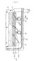
- FIG. 6 there is shown a diagrammatic illustration of construction of a cell stack used for the redox flow battery mentioned above.
- This type of battery usually uses the construction which is called a cell stack 200 comprising a plurality of cells stacked in layers.
- Each cell comprises the positive electrode 104 made of carbon felt and the negative electrode 105 made of carbon felt arranged at both sides of the membrane 103.
- Cell frames 210 are arranged at the outside of the positive electrode 104 and at the outside of the negative electrode 105, respectively.
- Each of the cell frames 210 comprises frames 212 made of plastic and a bipolar plate 211 made of a plastic carbon fixed in between the frames 212.
- the positive electrode 104 and the negative electrode 105 are adhesively bonded to the bipolar plate 211.
- End plates 201 are arranged at both sides of the stack body comprising the cell frames 210 and the electrodes 104, 105 and are clamped onto the both sides of the stack body by tightening nuts 203 screwed on rod-like members 202 piercing the both end plates 201.
- the end plate 201 commonly used comprises a rectangular plate 201A reinforced by a latticed frame 201B integrally formed on the rectangular plate 201A.
- the conventional cell stack 200 involves the adhesively bonding of the positive electrode 104 and the negative electrode 105 to the bipolar plate 211, leading to increase in the fabrication process.
- the bonding of the bipolar plate 211 to the electrodes 104, 105 by adhesive involves the disadvantage that due to deterioration of the adhesive, there is the possibility that the electrodes 104, 105 may peel off from the bipolar plate 211. This results in increase in electrical internal resistance of the battery, providing the problem of causing reduction of the battery efficiencies.
- the present invention provides a novel cell stack for a redox flow battery of a cell frame, electrodes and a membrane being stacked in layers, wherein the cell frame comprises a frame and a bipolar plate integrated with the frame, and the electrodes are put into close contact with the bipolar plate by a clamping force, without being adhesively bonded to the bipolar plate.
- the electrodes defined herein indicate a positive electrode and a negative electrode.
- the cell frame at a central portion of the cell stack in particular may be displaced downwardly from the original position.
- the out-of-position preventing member of the cell frame is interposed between "a stack body comprising the cell frame and the electrodes" and "the rod-like members of the clamping mechanism".
- the rod-like members themselves may double as the out-of-position preventing function by placing the rod-like members in contact with the cell frames, without using the out-of-position preventing member. But, in this case, there is no substantial clearance between the rod-like members and the cell frames, so that it is practically hard to assemble the cell stack. In contrast to this, the out-of-position preventing member provided separately from the rod-like members does not adversely affect the workability in assembling the cell stack.
- a plate-like member having a thickness corresponding to a distance between the rod-like members and the cell frames can preferably be used as the out-of-position preventing member. Since the out-of-position preventing member is placed in contact with the rod-like members, if the rod-like members do not have any insulating coating, then the out-of-position preventing member itself should preferably be formed of insulating material or the insulating coating should preferably be formed on the conductive out-of-position preventing member.
- FIG. 1 is a diagrammatic illustration of construction of a cell stack of the present invention.
- FIG. 2 is a plan view of a frame member used for the cell stack of the present invention.
- FIG. 3 is a plan view showing a combined state of the cell frame and electrodes used for the cell stack of the present invention.
- FIG. 4 is a plan view of an end plate.
- FIG. 5 is an explanatory view of an operating principle of the redox flow battery.
- FIG. 6 is an illustration of a conventional cell stack.
- FIG. 1 there is shown a diagrammatic illustration of construction of a cell stack of the present invention, when viewed from the top.
- the cell stack 1 has the construction wherein cell frames 2, electrodes 3, 4 and membranes 5 are stacked in layers to form a stack body and also feed/discharge plates 6 and end plates 7 are arranged at both ends of the stack body and are clamped onto both sides of the stack body by a clamping mechanism 8.
- An operating principle of a redox flow battery using the cell stack 1 is the same as that outlined with reference to FIG. 5.
- the electrolytes are circulated from tanks to the positive electrode 3 and the negative electrode 4, respectively, as in the same manner as conventional.
- the cell stack 1 is installed on the ground via a support base, not illustrated.
- the support base may be formed by an insulator set to isolate the cell stack from the ground.
- the cell frame 2 comprises a frame 2A and a bipolar plate 9 fixed on an inside of the frame.
- the frame 2A is a frame member formed of plastic comprising vinyl chloride.
- the bipolar plate 9 is a rectangular plate formed of conductive plastic carbon containing graphite.
- the frame member 20 has a plurality of manifolds 21A, 21B formed in its long sides.
- the manifolds 21A, 21B are arranged to form flow channels of the electrolytic solutions extending in a stacking direction of the cell frames when a number of cell frames are stacked in layers.
- the manifolds arranged along the long side of the frame member 20 are alternately used as a positive electrolyte manifold 21A and a negative electrolyte manifold 21B.
- the frame member 20 has, on a front side thereof, a circulation portion 22A of the electrolyte.
- the circulation portion 22A comprises an electrolyte guide groove 22A-1 extending from the manifold 21A and a rectifying portion 22A-2 for allowing the electrolyte fed from the guide groove 22A-1 to diffuse along an edge of the positive electrode.
- the rectifying portion 22A-2 is formed by rectangular projections and depressions formed along the long side of the frame member 20. The electrolyte is guided to the positive (negative) electrode through the depressions.
- the number and shape of the guide groove 22A-1 and of the rectifying portion 22A-2 are not limited to those illustrated in this embodiment.
- the guide groove 22A-1 in one long side of the frame member 20 and the guide groove 22A-1 in the other long side thereof are arranged to be symmetrical with respect to a point. This arrangement can provide the advantage that the frame members 20 can all be formed into the same configuration or there is no need to prepare the frame members 20 having different configurations, because they can be combined with each other by simply changing orientation.
- FIG. 3 Shown in FIG. 3 is a partial plan view showing the state in which the electrodes and a protection plate are arranged in the cell frame formed by joining the frame members together.
- the guide groove 22A-1 depicted by a solid line is formed on a front side of the frame 2A and the guide groove 22B-1 depicted by a broken line is formed on a back side of the frame 2A.
- the manifold on the left is the positive electrolyte manifold 21A.
- the positive electrolyte passing through the guide groove 22A-1 indicated by the solid line from this positive electrolyte manifold is guided to the positive electrode 3 disposed on the front side of the bipolar plate 9.
- the manifold on the right is the negative electrolyte manifold 21B.
- the negative electrolyte passing through the guide groove 22B-1 indicated by the broken line from this negative electrolyte manifold is guided to the negative electrode (not shown) disposed on the back side of the bipolar plate 9.
- the guide groove 22A-1 and the rectifying portion 22A-2 are covered with a plastic protection plate 23.
- the protection plate 23 has a circular hole formed in a position corresponding to the manifold 21A and also has a size to cover an entire area of the guide groove 22A-1 and the rectifying portion 22A-2 and an area extended slightly upwardly from the rectifying portion 22A-2.
- the membranes 5 In the cell stack 1 formed (FIG. 1), the membranes 5 (FIG. 1) are arranged on both sides of the cell frame 2 (FIG. 1).
- the protection plate 23 is used for protecting the thin membrane 5 from tear or damage caused by contact with the projections and depressions of the guide groove 22A-1 and rectifying portion 22A-2.
- the protection plate 23 is made of sufficient size to cover the area extended slightly upwardly from the rectifying portion 22A-1 as well, for the purpose of providing the function as a holder to hold upper and lower end portions of the positive electrode 3 (negative electrode 4) between the protection plate 23 and the bipolar plate 9, to thereby produce improved assembling workability.
- the protection plate 23 has thickness of the order of about 0.1-0.3mm.
- the frame 2A has a recessed portion 24 formed into a corresponding shape to the periphery of the protection plate 23 in the position where the protection plate 23 is mounted (See FIG. 2), thus facilitating the alignment of the protection plate 23.
- O-rings to seal the respective manifolds 21A, 21B and O-rings to prevent leakage of the electrolyte to the outside of the cell frames when the cell frames are stacked in layers are fitted in the circular grooves 25 formed around the manifolds and in frame grooves 26 formed along the outer periphery of the cell frame, respectively.
- the positive electrode 3 and the negative electrode are arranged on the front side and the back side of the bipolar plate 9, respectively.
- the positive (negative) electrode 3 is formed of the carbon felt and is formed to have a size corresponding to a rectangular space defined in the cell frame. It is usual that the positive (negative) electrode 3 is bonded to the bipolar plate 9 by adhesive, but, in the present invention, the form of the cell stack is held by a clamping force of a clamping mechanism mentioned later without using any adhesive.
- the frame 2A has a thickness larger than the bipolar plate 9. As a result, a level difference is produced between a surface of the frame 2A and a surface of the bipolar plate 9.
- the electrodes When incorporated in the cell stack, the electrodes are compressed to a thickness corresponding to the level difference.
- the repulsive force is preferably in the range of more than 15kPa to less than 150kPa (more than 0.153kgf/cm 2 to less than 1.53kgf/cm 2 ).
- a weight per unit area of the electrode is preferably in the range of 100g/m 2 or more to 1,000g/m 2 or less.
- An ion-exchange membrane is used for the membrane. It has thickness of the order of about 20-400 ⁇ m. Vinyl chloride, fluorocarbon resin, polyethylene, polypropylene and the like can be used as material of the membrane.
- the membrane has an area substantially equal to the cell frame and also has through holes formed in locations confronting the manifolds.
- the cell stack 1 has electrical terminals 10 disposed in the vicinity of both ends thereof for providing the charge/discharge operation as the redox flow battery.
- the cell stack 1 is formed by the cell frame 2, the positive electrode 3, the membrane 5, the negative electrode 4 and the cell frame 2 being repeatedly stacked in sequence, as shown in FIG. 1.
- the bipolar plate fixed in the interior of the cell frame 11 located at each end of the stack body thus formed is put into contact with the electrode 3, 4 located at the each end of the stack body, and the electrical terminal 10 is drawn out from the cell frame 11 located at the each end of the stack body.
- the feed and discharge plates 6 have the structure to connect the electrolyte tanks and the manifolds of the cell frames 2 so as to feed and discharge the electrodes to and from the manifolds.
- Pipes 12 are fitted in the feed and discharge plates 6 and also are connected to the electrolytic tanks.
- the pipes 12 are connected to the manifolds of the cell frames 2 through the electrolyte flow channels in the feed and discharge plates 6.
- the electrical terminals 10 and the pipes 12 are drawn out in the opposite direction from the cell stack 1 to make a distinction between a power line and a circulation line of the electrolyte, so as to facilitate a connecting work between the electrical terminals 10 and equipment and a connecting work between the pipes 12 and a piping to the tanks.
- this arrangement can provide a desirable result that even when the electrolyte leaks from the pipes 12, the electrical terminals 10 are kept out of the leakage of the electrolyte, thus preventing a flowing of electrical current to the power line.
- the end plates 7 are latticed plates for clamping onto both sides of the stack body comprising the cell frames 2, the electrodes 3, 4, the membranes 5 and the feed and discharge plates 6.
- a plan view of the end plate 7 is shown in FIG. 4.
- the latticed plates having empty spaces therein is adopted to provide reduction in weight of the end plate 7.
- the end plates 7 each have a number of through holes formed around a periphery 7A thereof. After rod-like members 8A mentioned later are inserted in the through holes, nuts 8B are tightened, thereby holding the stack structure comprising the cell frames 2, the electrodes 3, 4, the membranes 5 and the feed and discharge plates 6 (See FIG. 1).
- the clamping mechanism 8 serves to put the both end plates 7 into press-contact with both sides of the stack body to hold the stack body constructed as the cell stack 1, as shown in FIG. 1.
- the clamping mechanism 8 comprises the rod-like members 8A inserted in the through holes of the end plates 7 and the nuts 8B screwably engaged with the rod-like members 8A.
- Each rod-like member 8A has male threads formed at both ends thereof to be threadedly engaged with the nut 8B and an insulating coating formed by a thermal contraction tube at an intermediate portion thereof.
- a number of rod-like members 8A are arranged in parallel around the outside of the stack body.
- coil springs 13 are disposed around end portions of the rod-like members 8A between the nuts 8B and the end plates 7, to absorb thermal expansion and contraction of the cell stack 1.
- An out-of-position preventing plate (not shown) is disposed between a lower surface of the stack body of the cell frames 2 and the rod-like members 8A.
- the out-of-position preventing plate serves to prevent part of the cell frames 2 from being moved out of position when some impact is exerted on the cell stack 1 during transportation. No particular limitation is imposed on the material and configuration of the out-of-position preventing plate, as long as it can be interposed between the stack body of the cell frames 2 and the rod-like members 8A.
- Total number of cell frames 100 in total (A set of stack body with 25 cell frames stacked in layers is temporarily held, and four sets of stack bodies, each being temporarily held, are stacked in layers),
- Composition Vanadium ion concentration: 2.0 mol/L, Free sulfuric acid concentration: 2.0 mol/L, and Added phosphoric acid concentration: 0.3 mol/L, Quantity of electrolyte: 20m 3 ,
- the cell resistance can be reduced to 1.3 ⁇ ⁇ cm 2 or less, these ranges being found to be further preferable.
- the cell stack of the present invention is designed to hold the stack structure by a clamping force without adhesively bonding the bipolar plate to the electrodes. This can eliminate the adhesive bonding process of the bipolar plate and electrodes, thus achieving simplification of assembly processes. Also, the elimination of the adhesive bonding process can also eliminate the problem of deterioration in battery efficiency with deterioration of adhesive.
Landscapes
- Life Sciences & Earth Sciences (AREA)
- Engineering & Computer Science (AREA)
- Manufacturing & Machinery (AREA)
- Sustainable Development (AREA)
- Sustainable Energy (AREA)
- Chemical & Material Sciences (AREA)
- Chemical Kinetics & Catalysis (AREA)
- Electrochemistry (AREA)
- General Chemical & Material Sciences (AREA)
- Fuel Cell (AREA)
Abstract
Description
Outer size: 1,000mm wide, 800mm high, and 5mm thick,
Inner size: 900mm wide and 600mm high,
Frame groove: 3mm wide, 1mm deep, and 7.5mm in distance between grooves,
Level difference between frame and bipolar plate: 3.0mm,
Material: Resin comprising 50 mass% vinyl chloride and 50 mass% acrylonitrile-butadiene-styrene copolymer (ABS),
Manufacturing process: Injection molding,
Material: 50 mass% graphite-containing chlorinated polyethylene,
Repulsive force: 100kPa (1.0kgf/cm2),
Weight per unit area: 500g/m2,
Quantity of electrolyte: 20m3,
Rate of spring of coil spring: 1,000N/m,
Active coils: 3.0,
Contraction from free length of coil spring when clamped: 30mm,
Discharge possible power: 350kWH,
Others: It was found that even when the cell stack was thermally contracted during operation, no problem occurred and no leakage of electrolyte from between the cell frames occurred, either.
| Repulsive force (kPa) | Wight per unit area (g/m2) | Cell resistance (Ω · cm2) | State of Circulation | ||
| No. 1 | 15 | 90 | 3.10 | × | Excellent |
| No. 2 | 25 | 100 | 1.48 | ○ | Excellent |
| No. 3 | 40 | 250 | 1.21 | o ○ | Excellent |
| No. 4 | 83 | 300 | 1.13 | o ○ | Excellent |
| No. 5 | 90 | 350 | 1.02 | o ○ | Excellent |
| No.6 | 96 | 610 | 0.97 | o ○ | Excellent |
| No. 7 | 100 | 800 | 1.10 | o ○ | Excellent |
| No. 8 | 120 | 1,000 | 1.41 | ○ | Good |
| No. 9 | 150 | 1,200 | 1.81 | × | Uneven |
| o ○: Excellent ○: Good ×: No-good |
Claims (7)
- A cell stack for a redox flow battery of a cell frame, electrodes and a membrane being stacked in layers,
wherein the cell frame comprises a frame and a bipolar plate integrated with the frame, and
wherein the electrodes are put into close contact with the bipolar plate by a clamping force, without being adhesively bonded to the bipolar plate. - The cell stack for the redox flow battery according to Claim 1, wherein when the electrodes are compressed to thickness corresponding to a level difference between the frame and the bipolar plate, repulsive force of the electrodes is in the range of more than 15kPa to less than 150kPa (more than 0.153kgf/cm2 to less than 1.53kgf/cm2).
- The cell stack for the redox flow battery according to Claim 1, wherein the electrodes each have a weight per unit area of 100g/m2 or more to less than 1,200g/m2.
- The cell stack for the redox flow battery according to Claim 1, wherein the cell stack comprises end plates arranged at both ends thereof and a clamping mechanism for holding the cell frames and the electrodes in sandwich relation between the both end plates, and wherein the end plates are in the form of a latticed plate having empty spaces therein.
- The cell stack for the redox flow battery according to Claim 1, wherein the cell stack includes end plates arranged at both ends thereof and rod-like members used for holding the cell frames and the electrodes in sandwich relation between the both end plates, and
wherein the rod-like members are each provided with insulating coating. - The cell stack for the redox flow battery according to Claim 4 or 5, wherein the clamping mechanism includes elastic members for absorbing expansion and contraction of the cell stack in a direction of the cell frame and the electrodes being stacked in layers.
- The cell stack for the redox flow battery according to Claim 5, wherein an out-of-position preventing member of the cell frame is interposed between a stack body comprising the cell frame and the electrodes and the rod-like members.
Applications Claiming Priority (3)
| Application Number | Priority Date | Filing Date | Title |
|---|---|---|---|
| JP2001177240A JP3657538B2 (en) | 2001-06-12 | 2001-06-12 | Cell stack for redox flow battery |
| JP2001177240 | 2001-06-12 | ||
| PCT/JP2002/004444 WO2002101863A1 (en) | 2001-06-12 | 2002-05-07 | Cell stack for redox flow cell |
Publications (3)
| Publication Number | Publication Date |
|---|---|
| EP1411575A1 true EP1411575A1 (en) | 2004-04-21 |
| EP1411575A4 EP1411575A4 (en) | 2009-09-23 |
| EP1411575B1 EP1411575B1 (en) | 2012-01-25 |
Family
ID=19018111
Family Applications (1)
| Application Number | Title | Priority Date | Filing Date |
|---|---|---|---|
| EP02724708A Expired - Lifetime EP1411575B1 (en) | 2001-06-12 | 2002-05-07 | Cell stack for redox flow cell |
Country Status (8)
| Country | Link |
|---|---|
| US (1) | US9017869B2 (en) |
| EP (1) | EP1411575B1 (en) |
| JP (1) | JP3657538B2 (en) |
| CN (1) | CN1515047A (en) |
| AU (1) | AU2002255310B8 (en) |
| CA (1) | CA2450510C (en) |
| TW (1) | TW552728B (en) |
| WO (1) | WO2002101863A1 (en) |
Cited By (1)
| Publication number | Priority date | Publication date | Assignee | Title |
|---|---|---|---|---|
| WO2009040521A1 (en) * | 2007-09-25 | 2009-04-02 | Anthony John Maxwell | Power storage system wherein the electrolyte comprises acid mine drainage |
Families Citing this family (63)
| Publication number | Priority date | Publication date | Assignee | Title |
|---|---|---|---|---|
| US8277964B2 (en) | 2004-01-15 | 2012-10-02 | Jd Holding Inc. | System and method for optimizing efficiency and power output from a vanadium redox battery energy storage system |
| JP5068052B2 (en) * | 2006-09-29 | 2012-11-07 | 昭和電工株式会社 | FUEL CELL SEPARATOR, FUEL CELL CELL, FUEL CELL CELL UNIT, AND METHOD FOR PRODUCING FUEL CELL SEPARATOR AND FUEL CELL CELL UNIT |
| US7855005B2 (en) * | 2007-02-12 | 2010-12-21 | Deeya Energy, Inc. | Apparatus and methods of determination of state of charge in a redox flow battery |
| US8587150B2 (en) * | 2008-02-28 | 2013-11-19 | Deeya Energy, Inc. | Method and modular system for charging a battery |
| US7927731B2 (en) * | 2008-07-01 | 2011-04-19 | Deeya Energy, Inc. | Redox flow cell |
| US8785023B2 (en) | 2008-07-07 | 2014-07-22 | Enervault Corparation | Cascade redox flow battery systems |
| US7820321B2 (en) | 2008-07-07 | 2010-10-26 | Enervault Corporation | Redox flow battery system for distributed energy storage |
| CN101667646B (en) * | 2008-09-03 | 2011-11-09 | 中国科学院大连化学物理研究所 | Electrode frame structure for redox flow cell |
| US8231993B2 (en) * | 2008-10-10 | 2012-07-31 | Deeya Energy, Inc. | Flexible multi-walled tubing assembly |
| US8230736B2 (en) * | 2008-10-10 | 2012-07-31 | Deeya Energy, Inc. | Level sensor for conductive liquids |
| EP2351184A4 (en) * | 2008-10-10 | 2014-07-09 | Deeya Energy Technologies Inc | Method and apparatus for determining state of charge of a battery |
| CN102246338B (en) * | 2008-10-10 | 2014-06-11 | 迪亚能源股份有限公司 | Thermal control of a flow cell battery |
| WO2010042900A1 (en) * | 2008-10-10 | 2010-04-15 | Deeya Energy Technologies, Inc. | Methods for bonding porous flexible membranes using solvent |
| US8236463B2 (en) * | 2008-10-10 | 2012-08-07 | Deeya Energy, Inc. | Magnetic current collector |
| US20100092843A1 (en) * | 2008-10-10 | 2010-04-15 | Deeya Energy Technologies, Inc. | Venturi pumping system in a hydrogen gas circulation of a flow battery |
| US8349477B2 (en) * | 2009-05-28 | 2013-01-08 | Deeya Energy, Inc. | Optical leak detection sensor |
| CN102460812B (en) * | 2009-05-28 | 2014-12-31 | 艾默吉电力系统股份有限公司 | Preparation of flow battery electrolytes from raw materials |
| US8723489B2 (en) * | 2009-05-28 | 2014-05-13 | Deeya Energy, Inc. | Bi-directional buck-boost circuit |
| CN102460811B (en) * | 2009-05-28 | 2015-11-25 | 艾默吉电力系统股份有限公司 | Redox flow cell rebalancing |
| EP2436080A2 (en) * | 2009-05-28 | 2012-04-04 | Deeya Energy, Inc. | Electrolyte compositions |
| US8587255B2 (en) * | 2009-05-28 | 2013-11-19 | Deeya Energy, Inc. | Control system for a flow cell battery |
| US8551299B2 (en) * | 2009-05-29 | 2013-10-08 | Deeya Energy, Inc. | Methods of producing hydrochloric acid from hydrogen gas and chlorine gas |
| US8951665B2 (en) * | 2010-03-10 | 2015-02-10 | Imergy Power Systems, Inc. | Methods for the preparation of electrolytes for chromium-iron redox flow batteries |
| US20110177379A1 (en) * | 2010-03-25 | 2011-07-21 | Ford Global Technologies, Llc | Battery assembly |
| US8323818B2 (en) * | 2010-03-25 | 2012-12-04 | Ford Global Technologies, Llc | Battery cooling |
| US9123944B2 (en) * | 2010-03-25 | 2015-09-01 | Ford Global Technologies, Llc | Battery cover assembly |
| DE102010012936A1 (en) * | 2010-03-26 | 2011-09-29 | Daimler Ag | Cell network with a predefinable number of parallel and / or series electrically interconnected single cells |
| JP2011228059A (en) | 2010-04-16 | 2011-11-10 | Sumitomo Electric Ind Ltd | Dipole plate for redox flow battery |
| US10651492B2 (en) | 2010-06-22 | 2020-05-12 | Vrb Energy Inc. | Integrated system for electrochemical energy storage system |
| US9281535B2 (en) | 2010-08-12 | 2016-03-08 | Imergy Power Systems, Inc. | System dongle |
| US8709629B2 (en) | 2010-12-22 | 2014-04-29 | Jd Holding Inc. | Systems and methods for redox flow battery scalable modular reactant storage |
| CN103339762B (en) | 2011-01-13 | 2016-03-30 | 伊莫基动力系统公司 | Flow cell stack |
| US8980484B2 (en) | 2011-03-29 | 2015-03-17 | Enervault Corporation | Monitoring electrolyte concentrations in redox flow battery systems |
| US8916281B2 (en) | 2011-03-29 | 2014-12-23 | Enervault Corporation | Rebalancing electrolytes in redox flow battery systems |
| JP5477672B2 (en) | 2011-03-31 | 2014-04-23 | 住友電気工業株式会社 | Cell frame for electrolyte flow type battery, cell stack for electrolyte flow type battery, and electrolyte flow type battery |
| US10141594B2 (en) | 2011-10-07 | 2018-11-27 | Vrb Energy Inc. | Systems and methods for assembling redox flow battery reactor cells |
| KR101679940B1 (en) * | 2011-12-20 | 2016-11-25 | 유나이티드 테크놀로지스 코포레이션 | Flow battery with enhanced durability |
| US9853454B2 (en) | 2011-12-20 | 2017-12-26 | Jd Holding Inc. | Vanadium redox battery energy storage system |
| DE102012024753A1 (en) | 2012-12-19 | 2014-06-26 | Eisenhuth Gmbh & Co. Kg | Frame with integrated bipolar plate for electrochemical reactors, consists of electrically conductive bipolar plate(s) of thermoformable carbon-polymer composite material with thermoplastic polymer providing liquid-tight connection |
| FR3000108B1 (en) * | 2012-12-21 | 2015-02-27 | Commissariat Energie Atomique | ELECTRICAL INSULATION AND SEALING FRAME FOR WATER ELECTROLYSIS REACTOR (SOEC) OR FUEL CELL (SOFC). |
| USD756912S1 (en) * | 2013-02-04 | 2016-05-24 | Sumitomo Electric Industries, Ltd. | Redox flow battery cell stack |
| KR101431070B1 (en) | 2013-07-16 | 2014-08-21 | 주식회사 에이치투 | Stack for Redox Flow Battery with Membrane and Flow Frame Assembly |
| JP6098998B2 (en) * | 2013-09-12 | 2017-03-22 | 住友電気工業株式会社 | Battery cell stack and redox flow battery |
| KR101844566B1 (en) * | 2015-05-22 | 2018-04-03 | 지엔에스티주식회사 | Redoxflow battery using complexelectrode cell |
| KR101945529B1 (en) | 2015-07-07 | 2019-02-08 | 킴스테크날리지 주식회사 | Flow Battery |
| JP6066141B1 (en) * | 2015-07-24 | 2017-01-25 | 住友電気工業株式会社 | Redox flow battery electrode, redox flow battery, and electrode characteristic evaluation method |
| JP6540961B2 (en) | 2016-01-26 | 2019-07-10 | 住友電気工業株式会社 | Battery and seal material |
| JP6677045B2 (en) * | 2016-03-29 | 2020-04-08 | 住友電気工業株式会社 | Frame for redox flow battery, redox flow battery, and cell stack |
| JP6108008B1 (en) * | 2016-05-30 | 2017-04-05 | 住友電気工業株式会社 | Bipolar plate, cell frame and cell stack, and redox flow battery |
| WO2018066093A1 (en) * | 2016-10-05 | 2018-04-12 | 住友電気工業株式会社 | Cell stack and redox flow battery |
| DE112018000798T5 (en) | 2017-02-13 | 2019-12-12 | Ess Tech, Inc | LEAF SPRING COMPRESSION SYSTEM DESIGN |
| US11342572B2 (en) | 2017-08-09 | 2022-05-24 | Sumitomo Electric Industries, Ltd. | Redox flow battery |
| WO2019030903A1 (en) * | 2017-08-10 | 2019-02-14 | 住友電気工業株式会社 | Cell stack and redox flow battery |
| JP6991468B2 (en) * | 2018-02-27 | 2022-01-12 | 住友電気工業株式会社 | Cell stack and redox flow battery |
| US11056698B2 (en) | 2018-08-02 | 2021-07-06 | Raytheon Technologies Corporation | Redox flow battery with electrolyte balancing and compatibility enabling features |
| US11705571B2 (en) | 2018-09-05 | 2023-07-18 | Nikolai M. Kocherginsky | Foil-based redox flow battery |
| EP4128406A4 (en) * | 2020-05-15 | 2024-12-18 | ESS Tech, Inc. | Electrode assembly for a redox flow battery |
| CA3200839A1 (en) | 2020-11-09 | 2022-05-12 | Pdc Machines Inc. | Active oil injection system for a diaphragm compressor |
| US11271226B1 (en) | 2020-12-11 | 2022-03-08 | Raytheon Technologies Corporation | Redox flow battery with improved efficiency |
| US20230107172A1 (en) * | 2021-10-01 | 2023-04-06 | Lockheed Martin Energy, Llc | One-piece pressure plate collector |
| CN114050297B (en) * | 2021-10-19 | 2023-06-16 | 北京和瑞储能科技有限公司 | Automatic packing device and method for flow battery stack assembly |
| CN114039076A (en) | 2021-11-02 | 2022-02-11 | 北京普能世纪科技有限公司 | Distributed large-scale system of all-vanadium redox flow battery |
| WO2023080930A1 (en) | 2021-11-08 | 2023-05-11 | Pdc Machines Inc. | High-throughput diaphragm compressor |
Family Cites Families (15)
| Publication number | Priority date | Publication date | Assignee | Title |
|---|---|---|---|---|
| JPS61121267A (en) * | 1984-11-16 | 1986-06-09 | Sanyo Electric Co Ltd | Assembling fuel cell stacks |
| DK171869B1 (en) | 1985-10-22 | 1997-07-21 | Takeda Chemical Industries Ltd | Process for preparing 2-keto-L-gulonic acid and biologically pure microorganism culture for use in the process |
| JPH0630252B2 (en) * | 1986-08-02 | 1994-04-20 | 東邦レーヨン株式会社 | Electrode member for redox flow battery |
| JP2842600B2 (en) * | 1989-01-10 | 1999-01-06 | 関西電力 株式会社 | Cell stack for electrolyte circulating type secondary battery and cell stack mounting member |
| JPH03119665A (en) * | 1989-10-03 | 1991-05-22 | Toshiba Corp | Fuel cell fastening device |
| JPH03143613A (en) | 1989-10-31 | 1991-06-19 | Japan Steel Works Ltd:The | Identification method and device for solidification time in injection molding |
| JP2606335Y2 (en) * | 1992-06-29 | 2000-10-23 | 住友電気工業株式会社 | Redox flow battery cell |
| JPH07135008A (en) | 1993-11-09 | 1995-05-23 | Sumitomo Electric Ind Ltd | Battery cell structure |
| US5618641A (en) * | 1993-12-03 | 1997-04-08 | Bipolar Power Corporation | Bipolar battery construction |
| JPH087913A (en) | 1994-06-22 | 1996-01-12 | Kashima Kita Kyodo Hatsuden Kk | Full vanadium redox cell |
| JP2000067899A (en) * | 1998-08-20 | 2000-03-03 | Sumitomo Electric Ind Ltd | Redox flow type secondary battery cell stack |
| JP3143613B2 (en) | 1999-03-05 | 2001-03-07 | 住友電気工業株式会社 | Cell for redox flow type secondary battery |
| JP3601581B2 (en) | 1999-06-11 | 2004-12-15 | 東洋紡績株式会社 | Carbon electrode material for vanadium redox flow battery |
| JP2001006690A (en) * | 1999-06-21 | 2001-01-12 | Toyobo Co Ltd | Carbon electrode material |
| JP2001006691A (en) * | 1999-06-21 | 2001-01-12 | Toyobo Co Ltd | Carbon electrode material |
-
2001
- 2001-06-12 JP JP2001177240A patent/JP3657538B2/en not_active Expired - Fee Related
-
2002
- 2002-04-10 TW TW091107171A patent/TW552728B/en not_active IP Right Cessation
- 2002-05-07 CA CA002450510A patent/CA2450510C/en not_active Expired - Fee Related
- 2002-05-07 US US10/480,299 patent/US9017869B2/en not_active Expired - Fee Related
- 2002-05-07 WO PCT/JP2002/004444 patent/WO2002101863A1/en not_active Ceased
- 2002-05-07 CN CNA028116267A patent/CN1515047A/en active Pending
- 2002-05-07 EP EP02724708A patent/EP1411575B1/en not_active Expired - Lifetime
- 2002-05-07 AU AU2002255310A patent/AU2002255310B8/en not_active Ceased
Cited By (1)
| Publication number | Priority date | Publication date | Assignee | Title |
|---|---|---|---|---|
| WO2009040521A1 (en) * | 2007-09-25 | 2009-04-02 | Anthony John Maxwell | Power storage system wherein the electrolyte comprises acid mine drainage |
Also Published As
| Publication number | Publication date |
|---|---|
| TW552728B (en) | 2003-09-11 |
| US9017869B2 (en) | 2015-04-28 |
| JP3657538B2 (en) | 2005-06-08 |
| AU2002255310B2 (en) | 2007-09-20 |
| US20040241544A1 (en) | 2004-12-02 |
| CN1515047A (en) | 2004-07-21 |
| CA2450510C (en) | 2009-08-25 |
| WO2002101863A1 (en) | 2002-12-19 |
| CA2450510A1 (en) | 2002-12-19 |
| EP1411575A4 (en) | 2009-09-23 |
| JP2002367660A (en) | 2002-12-20 |
| EP1411575B1 (en) | 2012-01-25 |
| AU2002255310B8 (en) | 2008-12-11 |
Similar Documents
| Publication | Publication Date | Title |
|---|---|---|
| AU2002255310B2 (en) | Cell stack for redox flow battery | |
| AU2002253671B2 (en) | Cell frame for redox flow battery, and redox flow battery | |
| US11824243B2 (en) | Electrode assembly and flow battery with improved electrolyte distribution | |
| US7670719B2 (en) | Cell stack for redox flow battery, and redox flow battery | |
| US7384703B2 (en) | Fuel cell system | |
| US5858569A (en) | Low cost fuel cell stack design | |
| US11611098B2 (en) | Cell for flow battery | |
| JP2004172094A (en) | Fuel cell | |
| JP2006049129A (en) | Fuel cell stack | |
| US20050186462A1 (en) | PEM fuel cell stack with floating current collector plates | |
| US8343681B2 (en) | Bipolar plate and fuel cell stack including the same | |
| CN111082118B (en) | Flow cell stack | |
| US20090053581A1 (en) | Separator and fuel cell | |
| KR100792954B1 (en) | Electrical double layer capacitors | |
| TW201807876A (en) | Redox flow battery frame body, redox flow battery, and cell stack | |
| Park et al. | Cell for Flow Battery |
Legal Events
| Date | Code | Title | Description |
|---|---|---|---|
| PUAI | Public reference made under article 153(3) epc to a published international application that has entered the european phase |
Free format text: ORIGINAL CODE: 0009012 |
|
| 17P | Request for examination filed |
Effective date: 20040109 |
|
| AK | Designated contracting states |
Kind code of ref document: A1 Designated state(s): AT BE CH CY DE DK ES FI FR GB GR IE IT LI LU MC NL PT SE TR |
|
| A4 | Supplementary search report drawn up and despatched |
Effective date: 20090826 |
|
| RIC1 | Information provided on ipc code assigned before grant |
Ipc: H01M 8/18 20060101AFI20030103BHEP Ipc: H01M 8/24 20060101ALI20090820BHEP Ipc: H01M 8/02 20060101ALI20090820BHEP |
|
| 17Q | First examination report despatched |
Effective date: 20091120 |
|
| GRAP | Despatch of communication of intention to grant a patent |
Free format text: ORIGINAL CODE: EPIDOSNIGR1 |
|
| RIC1 | Information provided on ipc code assigned before grant |
Ipc: H01M 8/02 20060101ALI20110705BHEP Ipc: H01M 8/24 20060101ALI20110705BHEP Ipc: H01M 8/18 20060101AFI20110705BHEP |
|
| GRAS | Grant fee paid |
Free format text: ORIGINAL CODE: EPIDOSNIGR3 |
|
| GRAA | (expected) grant |
Free format text: ORIGINAL CODE: 0009210 |
|
| RAP1 | Party data changed (applicant data changed or rights of an application transferred) |
Owner name: THE KANSAI ELECTRIC POWER CO., INC. Owner name: SUMITOMO ELECTRIC INDUSTRIES, LTD. |
|
| AK | Designated contracting states |
Kind code of ref document: B1 Designated state(s): DE FR GB IT |
|
| REG | Reference to a national code |
Ref country code: GB Ref legal event code: FG4D |
|
| REG | Reference to a national code |
Ref country code: DE Ref legal event code: R096 Ref document number: 60242076 Country of ref document: DE Effective date: 20120322 |
|
| PLBE | No opposition filed within time limit |
Free format text: ORIGINAL CODE: 0009261 |
|
| STAA | Information on the status of an ep patent application or granted ep patent |
Free format text: STATUS: NO OPPOSITION FILED WITHIN TIME LIMIT |
|
| 26N | No opposition filed |
Effective date: 20121026 |
|
| REG | Reference to a national code |
Ref country code: DE Ref legal event code: R097 Ref document number: 60242076 Country of ref document: DE Effective date: 20121026 |
|
| REG | Reference to a national code |
Ref country code: FR Ref legal event code: PLFP Year of fee payment: 15 |
|
| REG | Reference to a national code |
Ref country code: FR Ref legal event code: PLFP Year of fee payment: 16 |
|
| REG | Reference to a national code |
Ref country code: FR Ref legal event code: PLFP Year of fee payment: 17 |
|
| PGFP | Annual fee paid to national office [announced via postgrant information from national office to epo] |
Ref country code: GB Payment date: 20180329 Year of fee payment: 17 |
|
| PGFP | Annual fee paid to national office [announced via postgrant information from national office to epo] |
Ref country code: DE Payment date: 20180424 Year of fee payment: 17 |
|
| PGFP | Annual fee paid to national office [announced via postgrant information from national office to epo] |
Ref country code: IT Payment date: 20180522 Year of fee payment: 17 Ref country code: FR Payment date: 20180412 Year of fee payment: 17 |
|
| REG | Reference to a national code |
Ref country code: DE Ref legal event code: R119 Ref document number: 60242076 Country of ref document: DE |
|
| GBPC | Gb: european patent ceased through non-payment of renewal fee |
Effective date: 20190507 |
|
| PG25 | Lapsed in a contracting state [announced via postgrant information from national office to epo] |
Ref country code: DE Free format text: LAPSE BECAUSE OF NON-PAYMENT OF DUE FEES Effective date: 20191203 Ref country code: GB Free format text: LAPSE BECAUSE OF NON-PAYMENT OF DUE FEES Effective date: 20190507 Ref country code: IT Free format text: LAPSE BECAUSE OF NON-PAYMENT OF DUE FEES Effective date: 20190507 |
|
| PG25 | Lapsed in a contracting state [announced via postgrant information from national office to epo] |
Ref country code: FR Free format text: LAPSE BECAUSE OF NON-PAYMENT OF DUE FEES Effective date: 20190531 |