EP1411566B1 - Sealing ring to be applied to connection holes of the cells of an accumulator - Google Patents
Sealing ring to be applied to connection holes of the cells of an accumulator Download PDFInfo
- Publication number
- EP1411566B1 EP1411566B1 EP03013031A EP03013031A EP1411566B1 EP 1411566 B1 EP1411566 B1 EP 1411566B1 EP 03013031 A EP03013031 A EP 03013031A EP 03013031 A EP03013031 A EP 03013031A EP 1411566 B1 EP1411566 B1 EP 1411566B1
- Authority
- EP
- European Patent Office
- Prior art keywords
- sheath
- ring
- accumulator
- hole
- sealing ring
- Prior art date
- Legal status (The legal status is an assumption and is not a legal conclusion. Google has not performed a legal analysis and makes no representation as to the accuracy of the status listed.)
- Revoked
Links
- 238000007789 sealing Methods 0.000 title claims abstract description 14
- 230000008878 coupling Effects 0.000 claims description 7
- 238000010168 coupling process Methods 0.000 claims description 7
- 238000005859 coupling reaction Methods 0.000 claims description 7
- 230000001681 protective effect Effects 0.000 description 7
- 238000003780 insertion Methods 0.000 description 6
- 230000037431 insertion Effects 0.000 description 6
- 238000003466 welding Methods 0.000 description 6
- 239000004743 Polypropylene Substances 0.000 description 3
- 239000003792 electrolyte Substances 0.000 description 3
- -1 polypropylene Polymers 0.000 description 3
- 229920001155 polypropylene Polymers 0.000 description 3
- 239000000463 material Substances 0.000 description 2
- 238000002844 melting Methods 0.000 description 2
- 230000008018 melting Effects 0.000 description 2
- 238000000465 moulding Methods 0.000 description 2
- 239000004417 polycarbonate Substances 0.000 description 2
- 229920000515 polycarbonate Polymers 0.000 description 2
- 238000004080 punching Methods 0.000 description 2
- RRHGJUQNOFWUDK-UHFFFAOYSA-N Isoprene Chemical compound CC(=C)C=C RRHGJUQNOFWUDK-UHFFFAOYSA-N 0.000 description 1
- 238000004519 manufacturing process Methods 0.000 description 1
- 238000000034 method Methods 0.000 description 1
- 238000012986 modification Methods 0.000 description 1
- 230000004048 modification Effects 0.000 description 1
- 229920001195 polyisoprene Polymers 0.000 description 1
Images

Classifications
-
- H—ELECTRICITY
- H01—ELECTRIC ELEMENTS
- H01M—PROCESSES OR MEANS, e.g. BATTERIES, FOR THE DIRECT CONVERSION OF CHEMICAL ENERGY INTO ELECTRICAL ENERGY
- H01M50/00—Constructional details or processes of manufacture of the non-active parts of electrochemical cells other than fuel cells, e.g. hybrid cells
- H01M50/10—Primary casings; Jackets or wrappings
- H01M50/172—Arrangements of electric connectors penetrating the casing
-
- H—ELECTRICITY
- H01—ELECTRIC ELEMENTS
- H01M—PROCESSES OR MEANS, e.g. BATTERIES, FOR THE DIRECT CONVERSION OF CHEMICAL ENERGY INTO ELECTRICAL ENERGY
- H01M50/00—Constructional details or processes of manufacture of the non-active parts of electrochemical cells other than fuel cells, e.g. hybrid cells
- H01M50/10—Primary casings; Jackets or wrappings
- H01M50/183—Sealing members
- H01M50/184—Sealing members characterised by their shape or structure
-
- H—ELECTRICITY
- H01—ELECTRIC ELEMENTS
- H01M—PROCESSES OR MEANS, e.g. BATTERIES, FOR THE DIRECT CONVERSION OF CHEMICAL ENERGY INTO ELECTRICAL ENERGY
- H01M50/00—Constructional details or processes of manufacture of the non-active parts of electrochemical cells other than fuel cells, e.g. hybrid cells
- H01M50/50—Current conducting connections for cells or batteries
- H01M50/528—Fixed electrical connections, i.e. not intended for disconnection
- H01M50/529—Intercell connections through partitions, e.g. in a battery casing
-
- H—ELECTRICITY
- H01—ELECTRIC ELEMENTS
- H01M—PROCESSES OR MEANS, e.g. BATTERIES, FOR THE DIRECT CONVERSION OF CHEMICAL ENERGY INTO ELECTRICAL ENERGY
- H01M50/00—Constructional details or processes of manufacture of the non-active parts of electrochemical cells other than fuel cells, e.g. hybrid cells
- H01M50/10—Primary casings; Jackets or wrappings
- H01M50/183—Sealing members
- H01M50/19—Sealing members characterised by the material
- H01M50/193—Organic material
-
- Y—GENERAL TAGGING OF NEW TECHNOLOGICAL DEVELOPMENTS; GENERAL TAGGING OF CROSS-SECTIONAL TECHNOLOGIES SPANNING OVER SEVERAL SECTIONS OF THE IPC; TECHNICAL SUBJECTS COVERED BY FORMER USPC CROSS-REFERENCE ART COLLECTIONS [XRACs] AND DIGESTS
- Y02—TECHNOLOGIES OR APPLICATIONS FOR MITIGATION OR ADAPTATION AGAINST CLIMATE CHANGE
- Y02E—REDUCTION OF GREENHOUSE GAS [GHG] EMISSIONS, RELATED TO ENERGY GENERATION, TRANSMISSION OR DISTRIBUTION
- Y02E60/00—Enabling technologies; Technologies with a potential or indirect contribution to GHG emissions mitigation
- Y02E60/10—Energy storage using batteries
Definitions
- the finding concerns a sealing ring to be applied to connection holes of the cells of an accumulator.
- electrical accumulators substantially consist of a container made from polypropylene equipped on the inside with a plurality of divider walls.
- the walls define cells inside which the elements of the accumulator and the electrolyte are arranged.
- the elements consist of a plurality of plates arranged interfacing each other and electrically and mechanically connected through connection rods made from lead, known as straps.
- the rods of the adjacent elements with opposite polarity are connected together through openings consisting of connection through holes with a frusto-conical cross-section made on the divider walls.
- the electromechanical connection is obtained by welding making an electrical current of an intensity such as the make the parts in contact melt pass through the rods.
- an insert is used, known as a sealing ring.
- the sealing ring comprises a circular plate equipped with a through hole axially to which is arranged a cylindrical sheath with a diameter equal to the connection hole and a length equal to or less than the thickness of the divider wall.
- the ring is coupled in the connection hole and is generally made from polycarbonate, which as known has a higher melting point than that of polypropylene.
- the sheath being placed between the divider wall and the connection rods prevents the wall itself from melting during welding.
- a sealing ring of the kind disclosed above is known from document FR 2 032 096; in particular, the sealing ring known from this document comprises a sheath made of caoutchouc and comprising two shoulders so as to recover both sides of the hole.
- a first drawback of the described sealing ring consists in the fact that the coupling with the connection hole is not stable and is not very reliable.
- a further drawback consists in the fact that the contact region between the cylindrical sheath and the surfaces of the connection hole is limited to an annular region near to the plate.
- the sheath has a circular cross-section whereas the connection hole has a frusto-conical cross-section.
- the purpose of the present finding is to overcome said drawbacks.
- a first purpose of the finding is to realise a sealing ring which stably coupled with the connection hole.
- a further purpose is to realise a ring which can be inserted in the corresponding connection hole even automatically and at a different time to the insertion of the elements of the accumulator.
- Another purpose is to realise a sealing ring which allows a better dissipation of the heat which develops during the welding of the rods.
- a further purpose is to realise a ring which is cost-effective and which can be realised by moulding.
- the last but not least purpose is to realise a protective ring which does not require specific tools for insertion in the corresponding connection hole.
- a protective ring to be applied to frustoconical connection holes of the divider walls of an accumulator, in accordance with the main claim.
- the reliability of the coupling does not depend upon the dimensional tolerances of the hole and of the cylindrical sheath but upon the geometric shape of the sheath itself.
- the reliability accomplished ensures that the ring, once inserted, does not accidentally detach from the wall, for example during the transportation of the container.
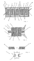
- the protective ring to be applied to frusto-conical connection holes 5 of the cells L of an accumulator A of the type represented in figure 1, object of the present finding, is represented in detail in figure 2, 3 and 4 where it is wholly indicated with reference numeral 1.
- the accumulator A substantially consists of a container B made from polypropylene equipped on the inside with a plurality of vertical divider walls P which define the cells L inside which the elements of the accumulator and the electrolyte are arranged.
- the elements E consist of a plurality of plates T arranged interfaced with each other electrically and mechanically connected through connection rods S made from lead.
- the sealing ring 1 comprises a plate 2 equipped with a through hole 3 axially to which is arranged the base 7 of a sheath 4, shown in detail in figure 2 and 3, suitable for coupling with the connection hole 5 made on the divider wall P.
- the sheath 4 has a portion of its cross-section with a diameter 8 greater than the diameter 9 of the base 7 of the sheath 4 itself.
- connection hole 5 is realised by punching and therefore has a substantially frusto-conical cross-section.
- the through hole 3 of the sheath 4 which allows the passage of the rods S has a circular cross-section and a length equal to or less than the thickness of the divider wall P.
- the plate 2 is circular shaped although in different embodiments it can be of different geometric shapes.
- a variant embodiment wholly indicated with reference numeral 100 in figure 4 and 5 differs from the previous embodiment in that the sheath 4a has a substantially frusto-conical outer longitudinal cross-section.
- the taper of the frusto-conical portion diverges moving away from said plate 2a.
- the angle defined by the intersection of the outer surface 41 of the sheath 4 with the plate 2, indicated with 6 in figure 3, is less than 90 degrees.
- such an angle 6 is preferably equal to the inclination of the walls of the connection hole 5.
- the outer profile of the sheath 4 is substantially matching the profile of the hole 5.
- Another embodiment which is not represented differs from the previous one in that a portion of the profile of the outer surface 41 of the sheath 4 is frusto-conical.
- sheath 4b has the through hole 31 with a frusto-conical cross-section.
- the insertion of the protective ring 1 in the hole 5 foresees that the operator or a manipulator arranges the ring itself at the hole and then forces it against the wall.
- the flexibility of the ring 1 and in particular of the sheath 4 allows the latter to deform until it snaps into the hole 5.
- the flexibility of the sheath 4 substantially depends upon both the small size of the sheath and the intrinsic characteristics of the material used to realise it which, as stated previously, is polycarbonate or alternative materials.
Landscapes
- Chemical & Material Sciences (AREA)
- Chemical Kinetics & Catalysis (AREA)
- Electrochemistry (AREA)
- General Chemical & Material Sciences (AREA)
- Connection Of Batteries Or Terminals (AREA)
- Sealing Battery Cases Or Jackets (AREA)
- External Artificial Organs (AREA)
Abstract
Description
- The finding concerns a sealing ring to be applied to connection holes of the cells of an accumulator.
- As it is known, electrical accumulators substantially consist of a container made from polypropylene equipped on the inside with a plurality of divider walls. The walls define cells inside which the elements of the accumulator and the electrolyte are arranged.
- The elements consist of a plurality of plates arranged interfacing each other and electrically and mechanically connected through connection rods made from lead, known as straps.
- The rods of the adjacent elements with opposite polarity are connected together through openings consisting of connection through holes with a frusto-conical cross-section made on the divider walls.
- The electromechanical connection is obtained by welding making an electrical current of an intensity such as the make the parts in contact melt pass through the rods.
- To avoid the electrolyte flowing from one cell to the other and to avoid the divider wall being damaged during welding, an insert is used, known as a sealing ring.
- The sealing ring comprises a circular plate equipped with a through hole axially to which is arranged a cylindrical sheath with a diameter equal to the connection hole and a length equal to or less than the thickness of the divider wall.
- The ring is coupled in the connection hole and is generally made from polycarbonate, which as known has a higher melting point than that of polypropylene.
- The sheath being placed between the divider wall and the connection rods prevents the wall itself from melting during welding.
- The circular plate which is placed in contact with the divider wall carries out the function of a gasket and ensures the airtight seal of each cell. A sealing ring of the kind disclosed above is known from
document FR 2 032 096; in particular, the sealing ring known from this document comprises a sheath made of caoutchouc and comprising two shoulders so as to recover both sides of the hole. - A first drawback of the described sealing ring consists in the fact that the coupling with the connection hole is not stable and is not very reliable.
- This is substantially due to the fact that both the sealing ring and the connection hole are obtained by moulding or punching and therefore have dimensional tolerances that cannot guarantee an ideal coupling.
- Another drawback linked to the previous one consists in the fact that the sealing ring must be inserted manually and contextually to the arranged of the elements. This is to avoid the ring accidentally detaching from the wall.
- A further drawback consists in the fact that the contact region between the cylindrical sheath and the surfaces of the connection hole is limited to an annular region near to the plate.
- This is substantially due to the fact that, as stated previously, the sheath has a circular cross-section whereas the connection hole has a frusto-conical cross-section.
- Another drawback linked to the previous one consists in the fact that the limited contact surface between sheath and the surfaces of the connection hole does not allow an ideal dissipation of the heat which develops during the welding of the rods. Moreover, the heat concentrating in the annular contact region can compromise the airtight seal of the cell.
- The purpose of the present finding is to overcome said drawbacks.
- In particular, a first purpose of the finding is to realise a sealing ring which stably coupled with the connection hole.
- A further purpose is to realise a ring which can be inserted in the corresponding connection hole even automatically and at a different time to the insertion of the elements of the accumulator.
- Another purpose is to realise a sealing ring which allows a better dissipation of the heat which develops during the welding of the rods.
- A further purpose is to realise a ring which is cost-effective and which can be realised by moulding.
- The last but not least purpose is to realise a protective ring which does not require specific tools for insertion in the corresponding connection hole.
- Said purposes are accomplished by a protective ring to be applied to frustoconical connection holes of the divider walls of an accumulator, in accordance with the main claim.
- Advantageously, the reliability of the coupling does not depend upon the dimensional tolerances of the hole and of the cylindrical sheath but upon the geometric shape of the sheath itself.
- Again advantageously, the reliability accomplished ensures that the ring, once inserted, does not accidentally detach from the wall, for example during the transportation of the container.
- This allows such an assembly step to be moved to any point in the production chain of the accumulator.
- Said purposes and advantages shall be made clearer during the description of a preferred embodiment given for indicating and not limiting purposes with reference to the attached tables of drawings, where:
- figure 1 represents a top view of a section of an accumulator equipped with the protective ring object of the finding;
- figure 2 represents a section view of the protective ring object of the finding inserted in a connection hole;
- figure 3 represents another section view of the ring of figure 2 before insertion in a corresponding connection hole;
- figure 4 represents a section view of a variant embodiment of the ring of figure 2 before insertion in a corresponding connection hole;
- figure 5 represents a section view of the ring of figure 4 inserted in a corresponding connection hole.
- figure 6 represents a section view of another variant embodiment of the ring of figure 2 before insertion in a corresponding connection hole;
- figure 7 represents a section view of the ring of figure 6 inserted in a corresponding connection hole.
- The protective ring to be applied to frusto-
conical connection holes 5 of the cells L of an accumulator A of the type represented in figure 1, object of the present finding, is represented in detail in figure 2, 3 and 4 where it is wholly indicated withreference numeral 1. - The accumulator A substantially consists of a container B made from polypropylene equipped on the inside with a plurality of vertical divider walls P which define the cells L inside which the elements of the accumulator and the electrolyte are arranged.
- The elements E, as stated previously, consist of a plurality of plates T arranged interfaced with each other electrically and mechanically connected through connection rods S made from lead.
- As far as the
sealing ring 1 is concerned, it comprises aplate 2 equipped with a throughhole 3 axially to which is arranged the base 7 of asheath 4, shown in detail in figure 2 and 3, suitable for coupling with theconnection hole 5 made on the divider wall P. - The finding foresees that the
sheath 4 has a portion of its cross-section with adiameter 8 greater than thediameter 9 of the base 7 of thesheath 4 itself. - This realises an undercut which prevents the accidental decoupling of the
protective ring 1 from thehole 5. - It should be observed that the
connection hole 5 is realised by punching and therefore has a substantially frusto-conical cross-section. - The through
hole 3 of thesheath 4 which allows the passage of the rods S has a circular cross-section and a length equal to or less than the thickness of the divider wall P. - As far as the
plate 2 is concerned, it is circular shaped although in different embodiments it can be of different geometric shapes. - A variant embodiment wholly indicated with
reference numeral 100 in figure 4 and 5 differs from the previous embodiment in that the sheath 4a has a substantially frusto-conical outer longitudinal cross-section. - In particular, the taper of the frusto-conical portion diverges moving away from
said plate 2a. - The angle defined by the intersection of the outer surface 41 of the
sheath 4 with theplate 2, indicated with 6 in figure 3, is less than 90 degrees. - More generally, such an angle 6 is preferably equal to the inclination of the walls of the
connection hole 5. - It should also be observed that the outer profile of the
sheath 4 is substantially matching the profile of thehole 5. - Another embodiment which is not represented differs from the previous one in that a portion of the profile of the outer surface 41 of the
sheath 4 is frusto-conical. - Another variant embodiment wholly indicated with
reference numeral 101 in figure 6 differs in that thesheath 4b has the throughhole 31 with a frusto-conical cross-section. - The insertion of the
protective ring 1 in thehole 5 foresees that the operator or a manipulator arranges the ring itself at the hole and then forces it against the wall. - The flexibility of the
ring 1 and in particular of thesheath 4 allows the latter to deform until it snaps into thehole 5. - The flexibility of the
sheath 4 substantially depends upon both the small size of the sheath and the intrinsic characteristics of the material used to realise it which, as stated previously, is polycarbonate or alternative materials. - The reliability of the coupling is ensured in this case by the interference of the protrusion of the
sheath 4 with the walls of thehole 5. - This allows a coupling which is secure to be obtained and such as to allow the transportation and movement of the container B without the risk of the
ring 1 detaching from the wall P. - The assembly of the elements and of the accumulator can thus be carried out even at different times and places, following the known procedures already described.
- It is important to observe how the proposed solution allows
rings - It should also be observed that the proposed ring, especially in the embodiments indicated with 100 and 101, allows a better dissipation of the heat which develops in the welding step of the rods S.
- This is due to the fact the whole outer surface of the
sheath 4a and 4b is in contact with thewalls 51 of theconnection hole 5. - Although the finding has been described referring to the attached tables of drawings, it can undergo modifications in the embodiment step, all covered by the same inventive concept expressed by the claims shown hereafter and therefore protected by the present patent.
Claims (6)
- Sealing ring (1, 100, 101) to be applied to frusto-conical connection holes (5) of the divider walls (P) of an accumulator (A), said ring comprising a plate (2, 2a) equipped with a through hole (3, 31) axially to which is arranged the base (7) of a sheath (4, 4a, 4b) suitable for coupling in said connection hole (5) characterized in that the outer surface (41) of said sheath (4a, 4b) is substantially frusto-conical so as to substantially match the profile of the hole (5).
- Ring (100, 101) according to claim 1 characterized in that the taper of said frusto-conical sheath diverges moving away from said plate (2, 2a).
- Ring (100, 101) according to any one of the previous claims characterized in that the inner surface of said sheath (4b) is frusto-conical.
- Ring (100, 101) according to any one of the previous claims characterized in that said plate (2, 2a) is substantially circular.
- Ring (1, 100, 101) according to any one of the previous claims characterized in that said sheath (4, 4a, 4b) has a length equal to the thickness of the divider wall (P) of said accumulator (A).
- Ring (1, 100, 101) according to any one of claims 1 to 4 characterized in that said sheath (4, 4a, 4b) has a length less than the thickness of the divider walls (P) of said accumulator (A).
Priority Applications (2)
| Application Number | Priority Date | Filing Date | Title |
|---|---|---|---|
| DE20321812U DE20321812U1 (en) | 2002-06-11 | 2003-06-10 | Sealing ring for use at connection holes of cells of a rechargeable battery |
| US12/000,157 US7868255B2 (en) | 2002-06-11 | 2007-12-10 | Sealing ring to be applied to connection holes of cells of an accumulator |
Applications Claiming Priority (2)
| Application Number | Priority Date | Filing Date | Title |
|---|---|---|---|
| IT2002VI000018U ITVI20020018U1 (en) | 2002-06-11 | 2002-06-11 | SEAL RING TO BE APPLIED TO THE CONNECTION HOLES OF THE ACCUMULATOR CELLS |
| ITVI20020018 | 2002-06-11 |
Publications (2)
| Publication Number | Publication Date |
|---|---|
| EP1411566A1 EP1411566A1 (en) | 2004-04-21 |
| EP1411566B1 true EP1411566B1 (en) | 2005-12-07 |
Family
ID=30013058
Family Applications (1)
| Application Number | Title | Priority Date | Filing Date |
|---|---|---|---|
| EP03013031A Revoked EP1411566B1 (en) | 2002-06-11 | 2003-06-10 | Sealing ring to be applied to connection holes of the cells of an accumulator |
Country Status (5)
| Country | Link |
|---|---|
| EP (1) | EP1411566B1 (en) |
| AT (1) | ATE312414T1 (en) |
| DE (2) | DE20321812U1 (en) |
| ES (1) | ES2253607T3 (en) |
| IT (1) | ITVI20020018U1 (en) |
Family Cites Families (6)
| Publication number | Priority date | Publication date | Assignee | Title |
|---|---|---|---|---|
| GB1114332A (en) * | 1965-08-06 | 1968-05-22 | Dunlop Rubber Australia Ltd | Improvements relating to plate assemblies for multi-cell batteries |
| FR2032096A5 (en) * | 1969-02-19 | 1970-11-20 | Fulmen | |
| GB1476308A (en) * | 1973-08-25 | 1977-06-10 | Lucas Batteries Ltd | Method of making an electrical interconnection between battery plates in a pair of adjacent cells of an electric storage battery |
| US4508797A (en) * | 1983-07-26 | 1985-04-02 | The United States Of America As Represented By The United States Department Of Energy | Hermetically sealed electrical feedthrough for high temperature secondary cells |
| EP0244683A1 (en) * | 1986-05-08 | 1987-11-11 | Globe-Union Inc. | Apparatus for sealing a battery terminal post |
| GB9816444D0 (en) * | 1998-07-28 | 1998-09-23 | Aahb Patents Holdings Sa | Electrochemical cell |
-
2002
- 2002-06-11 IT IT2002VI000018U patent/ITVI20020018U1/en unknown
-
2003
- 2003-06-10 ES ES03013031T patent/ES2253607T3/en not_active Expired - Lifetime
- 2003-06-10 EP EP03013031A patent/EP1411566B1/en not_active Revoked
- 2003-06-10 DE DE20321812U patent/DE20321812U1/en not_active Expired - Lifetime
- 2003-06-10 AT AT03013031T patent/ATE312414T1/en not_active IP Right Cessation
- 2003-06-10 DE DE60302630T patent/DE60302630T2/en not_active Revoked
Also Published As
| Publication number | Publication date |
|---|---|
| ES2253607T3 (en) | 2006-06-01 |
| DE60302630T2 (en) | 2006-09-07 |
| DE60302630D1 (en) | 2006-01-12 |
| ITVI20020018U1 (en) | 2003-12-11 |
| DE20321812U1 (en) | 2010-09-09 |
| ATE312414T1 (en) | 2005-12-15 |
| EP1411566A1 (en) | 2004-04-21 |
Similar Documents
| Publication | Publication Date | Title |
|---|---|---|
| US6312852B1 (en) | Battery cell cover with flexible positive post terminal | |
| JP4184894B2 (en) | Cap assembly, secondary battery including the cap assembly, and method of manufacturing the cap assembly | |
| US20100143795A1 (en) | Battery and a Process for Making a Battery | |
| US6110617A (en) | Flooded lead acid battery with roll-over capability | |
| EP2253035B1 (en) | Cover for lead acid batteries | |
| US9520590B2 (en) | Sealable terminal for rechargeable battery | |
| US4544078A (en) | Sealed closure for sealing and closing an opening in a container | |
| US11276895B2 (en) | Top cap for secondary battery, secondary battery, and method for manufacturing the secondary battery | |
| US20110250493A1 (en) | Battery parts and associated methods of manufacture and use | |
| KR20180021708A (en) | A battery cell housing, a support, a method for grouping a plurality of battery cell housings | |
| US20110262806A1 (en) | Battery parts having retaining and sealing features, and associated methods of manufacture and use | |
| EP1411566B1 (en) | Sealing ring to be applied to connection holes of the cells of an accumulator | |
| US7868255B2 (en) | Sealing ring to be applied to connection holes of cells of an accumulator | |
| EP0263050B1 (en) | Hermetic terminal assembly and method of manufacturing same | |
| EP1184916A3 (en) | Sealed type lead acid battery | |
| FI66264B (en) | POLLULTSGENOMFOERING I LOCKET TILL HOELJET HOS EN ELEKTRISK ACUMULATOR | |
| US1248768A (en) | Storage battery. | |
| KR102351248B1 (en) | Case for secondary battery, secondary battery and battery module | |
| JPS5979967A (en) | Sealing feed through for alkaline battery assembly | |
| EP1062705B1 (en) | Sealing structure for terminal posts of batteries | |
| GB2026761A (en) | Accumulator terminal assemblies | |
| EP0214077B1 (en) | Seal, especially for a battery terminal | |
| KR102835534B1 (en) | Space adjuster apparatus and sealing facility for secondary battery including thereof | |
| KR19980063603A (en) | Rechargeable button battery and manufacturing method | |
| EP3716356B1 (en) | Cell holder for cylindrical cells |
Legal Events
| Date | Code | Title | Description |
|---|---|---|---|
| PUAI | Public reference made under article 153(3) epc to a published international application that has entered the european phase |
Free format text: ORIGINAL CODE: 0009012 |
|
| AK | Designated contracting states |
Kind code of ref document: A1 Designated state(s): AT BE BG CH CY CZ DE DK EE ES FI FR GB GR HU IE IT LI LU MC NL PT RO SE SI SK TR |
|
| AX | Request for extension of the european patent |
Extension state: AL LT LV MK |
|
| 17P | Request for examination filed |
Effective date: 20041021 |
|
| AKX | Designation fees paid |
Designated state(s): AT BE BG CH CY CZ DE DK EE ES FI FR GB GR HU IE IT LI LU MC NL PT RO SE SI SK TR |
|
| 17Q | First examination report despatched |
Effective date: 20041201 |
|
| GRAP | Despatch of communication of intention to grant a patent |
Free format text: ORIGINAL CODE: EPIDOSNIGR1 |
|
| RTI1 | Title (correction) |
Free format text: SEALING RING TO BE APPLIED TO CONNECTION HOLES OF THE CELLS OF AN ACCUMULATOR |
|
| GRAS | Grant fee paid |
Free format text: ORIGINAL CODE: EPIDOSNIGR3 |
|
| GRAA | (expected) grant |
Free format text: ORIGINAL CODE: 0009210 |
|
| AK | Designated contracting states |
Kind code of ref document: B1 Designated state(s): AT BE BG CH CY CZ DE DK EE ES FI FR GB GR HU IE IT LI LU MC NL PT RO SE SI SK TR |
|
| PG25 | Lapsed in a contracting state [announced via postgrant information from national office to epo] |
Ref country code: NL Free format text: LAPSE BECAUSE OF FAILURE TO SUBMIT A TRANSLATION OF THE DESCRIPTION OR TO PAY THE FEE WITHIN THE PRESCRIBED TIME-LIMIT Effective date: 20051207 Ref country code: SI Free format text: LAPSE BECAUSE OF FAILURE TO SUBMIT A TRANSLATION OF THE DESCRIPTION OR TO PAY THE FEE WITHIN THE PRESCRIBED TIME-LIMIT Effective date: 20051207 Ref country code: LI Free format text: LAPSE BECAUSE OF FAILURE TO SUBMIT A TRANSLATION OF THE DESCRIPTION OR TO PAY THE FEE WITHIN THE PRESCRIBED TIME-LIMIT Effective date: 20051207 Ref country code: SK Free format text: LAPSE BECAUSE OF FAILURE TO SUBMIT A TRANSLATION OF THE DESCRIPTION OR TO PAY THE FEE WITHIN THE PRESCRIBED TIME-LIMIT Effective date: 20051207 Ref country code: RO Free format text: LAPSE BECAUSE OF FAILURE TO SUBMIT A TRANSLATION OF THE DESCRIPTION OR TO PAY THE FEE WITHIN THE PRESCRIBED TIME-LIMIT Effective date: 20051207 Ref country code: BE Free format text: LAPSE BECAUSE OF FAILURE TO SUBMIT A TRANSLATION OF THE DESCRIPTION OR TO PAY THE FEE WITHIN THE PRESCRIBED TIME-LIMIT Effective date: 20051207 Ref country code: CH Free format text: LAPSE BECAUSE OF FAILURE TO SUBMIT A TRANSLATION OF THE DESCRIPTION OR TO PAY THE FEE WITHIN THE PRESCRIBED TIME-LIMIT Effective date: 20051207 Ref country code: FI Free format text: LAPSE BECAUSE OF FAILURE TO SUBMIT A TRANSLATION OF THE DESCRIPTION OR TO PAY THE FEE WITHIN THE PRESCRIBED TIME-LIMIT Effective date: 20051207 Ref country code: AT Free format text: LAPSE BECAUSE OF FAILURE TO SUBMIT A TRANSLATION OF THE DESCRIPTION OR TO PAY THE FEE WITHIN THE PRESCRIBED TIME-LIMIT Effective date: 20051207 |
|
| REG | Reference to a national code |
Ref country code: GB Ref legal event code: FG4D |
|
| REG | Reference to a national code |
Ref country code: CH Ref legal event code: EP |
|
| REG | Reference to a national code |
Ref country code: IE Ref legal event code: FG4D |
|
| REF | Corresponds to: |
Ref document number: 60302630 Country of ref document: DE Date of ref document: 20060112 Kind code of ref document: P |
|
| PG25 | Lapsed in a contracting state [announced via postgrant information from national office to epo] |
Ref country code: GR Free format text: LAPSE BECAUSE OF FAILURE TO SUBMIT A TRANSLATION OF THE DESCRIPTION OR TO PAY THE FEE WITHIN THE PRESCRIBED TIME-LIMIT Effective date: 20060307 Ref country code: SE Free format text: LAPSE BECAUSE OF FAILURE TO SUBMIT A TRANSLATION OF THE DESCRIPTION OR TO PAY THE FEE WITHIN THE PRESCRIBED TIME-LIMIT Effective date: 20060307 Ref country code: BG Free format text: LAPSE BECAUSE OF FAILURE TO SUBMIT A TRANSLATION OF THE DESCRIPTION OR TO PAY THE FEE WITHIN THE PRESCRIBED TIME-LIMIT Effective date: 20060307 Ref country code: DK Free format text: LAPSE BECAUSE OF FAILURE TO SUBMIT A TRANSLATION OF THE DESCRIPTION OR TO PAY THE FEE WITHIN THE PRESCRIBED TIME-LIMIT Effective date: 20060307 |
|
| PG25 | Lapsed in a contracting state [announced via postgrant information from national office to epo] |
Ref country code: PT Free format text: LAPSE BECAUSE OF FAILURE TO SUBMIT A TRANSLATION OF THE DESCRIPTION OR TO PAY THE FEE WITHIN THE PRESCRIBED TIME-LIMIT Effective date: 20060508 |
|
| NLV1 | Nl: lapsed or annulled due to failure to fulfill the requirements of art. 29p and 29m of the patents act | ||
| REG | Reference to a national code |
Ref country code: ES Ref legal event code: FG2A Ref document number: 2253607 Country of ref document: ES Kind code of ref document: T3 |
|
| PG25 | Lapsed in a contracting state [announced via postgrant information from national office to epo] |
Ref country code: HU Free format text: LAPSE BECAUSE OF FAILURE TO SUBMIT A TRANSLATION OF THE DESCRIPTION OR TO PAY THE FEE WITHIN THE PRESCRIBED TIME-LIMIT Effective date: 20060608 |
|
| PG25 | Lapsed in a contracting state [announced via postgrant information from national office to epo] |
Ref country code: IE Free format text: LAPSE BECAUSE OF NON-PAYMENT OF DUE FEES Effective date: 20060612 |
|
| REG | Reference to a national code |
Ref country code: CH Ref legal event code: PL |
|
| PG25 | Lapsed in a contracting state [announced via postgrant information from national office to epo] |
Ref country code: MC Free format text: LAPSE BECAUSE OF NON-PAYMENT OF DUE FEES Effective date: 20060630 |
|
| ET | Fr: translation filed | ||
| PLBI | Opposition filed |
Free format text: ORIGINAL CODE: 0009260 |
|
| 26 | Opposition filed |
Opponent name: ACCUMA S.P.A. Effective date: 20060907 |
|
| PLAX | Notice of opposition and request to file observation + time limit sent |
Free format text: ORIGINAL CODE: EPIDOSNOBS2 |
|
| PLBB | Reply of patent proprietor to notice(s) of opposition received |
Free format text: ORIGINAL CODE: EPIDOSNOBS3 |
|
| REG | Reference to a national code |
Ref country code: IE Ref legal event code: MM4A |
|
| PG25 | Lapsed in a contracting state [announced via postgrant information from national office to epo] |
Ref country code: EE Free format text: LAPSE BECAUSE OF FAILURE TO SUBMIT A TRANSLATION OF THE DESCRIPTION OR TO PAY THE FEE WITHIN THE PRESCRIBED TIME-LIMIT Effective date: 20051207 |
|
| PG25 | Lapsed in a contracting state [announced via postgrant information from national office to epo] |
Ref country code: LU Free format text: LAPSE BECAUSE OF NON-PAYMENT OF DUE FEES Effective date: 20060610 |
|
| PGFP | Annual fee paid to national office [announced via postgrant information from national office to epo] |
Ref country code: TR Payment date: 20080604 Year of fee payment: 6 |
|
| PG25 | Lapsed in a contracting state [announced via postgrant information from national office to epo] |
Ref country code: CY Free format text: LAPSE BECAUSE OF FAILURE TO SUBMIT A TRANSLATION OF THE DESCRIPTION OR TO PAY THE FEE WITHIN THE PRESCRIBED TIME-LIMIT Effective date: 20051207 |
|
| APBM | Appeal reference recorded |
Free format text: ORIGINAL CODE: EPIDOSNREFNO |
|
| APBP | Date of receipt of notice of appeal recorded |
Free format text: ORIGINAL CODE: EPIDOSNNOA2O |
|
| APAH | Appeal reference modified |
Free format text: ORIGINAL CODE: EPIDOSCREFNO |
|
| APBQ | Date of receipt of statement of grounds of appeal recorded |
Free format text: ORIGINAL CODE: EPIDOSNNOA3O |
|
| PGFP | Annual fee paid to national office [announced via postgrant information from national office to epo] |
Ref country code: CZ Payment date: 20090526 Year of fee payment: 7 Ref country code: IT Payment date: 20090624 Year of fee payment: 7 |
|
| PGFP | Annual fee paid to national office [announced via postgrant information from national office to epo] |
Ref country code: ES Payment date: 20090709 Year of fee payment: 7 |
|
| PGFP | Annual fee paid to national office [announced via postgrant information from national office to epo] |
Ref country code: DE Payment date: 20090604 Year of fee payment: 7 Ref country code: GB Payment date: 20090610 Year of fee payment: 7 |
|
| APBU | Appeal procedure closed |
Free format text: ORIGINAL CODE: EPIDOSNNOA9O |
|
| RDAF | Communication despatched that patent is revoked |
Free format text: ORIGINAL CODE: EPIDOSNREV1 |
|
| RDAG | Patent revoked |
Free format text: ORIGINAL CODE: 0009271 |
|
| STAA | Information on the status of an ep patent application or granted ep patent |
Free format text: STATUS: PATENT REVOKED |
|
| 27W | Patent revoked |
Effective date: 20100304 |
|
| PG25 | Lapsed in a contracting state [announced via postgrant information from national office to epo] |
Ref country code: TR Free format text: LAPSE BECAUSE OF NON-PAYMENT OF DUE FEES Effective date: 20090610 |
|
| PGFP | Annual fee paid to national office [announced via postgrant information from national office to epo] |
Ref country code: FR Payment date: 20090611 Year of fee payment: 7 |