EP1411564B1 - Method for preventing erroneous mounting of mounting part on main body device, mounting part and battery pack used for this - Google Patents
Method for preventing erroneous mounting of mounting part on main body device, mounting part and battery pack used for this Download PDFInfo
- Publication number
- EP1411564B1 EP1411564B1 EP02749359A EP02749359A EP1411564B1 EP 1411564 B1 EP1411564 B1 EP 1411564B1 EP 02749359 A EP02749359 A EP 02749359A EP 02749359 A EP02749359 A EP 02749359A EP 1411564 B1 EP1411564 B1 EP 1411564B1
- Authority
- EP
- European Patent Office
- Prior art keywords
- battery
- terminal
- battery pack
- mentioned
- refer
- Prior art date
- Legal status (The legal status is an assumption and is not a legal conclusion. Google has not performed a legal analysis and makes no representation as to the accuracy of the status listed.)
- Expired - Fee Related
Links
Images


Classifications
-
- H—ELECTRICITY
- H01—ELECTRIC ELEMENTS
- H01M—PROCESSES OR MEANS, e.g. BATTERIES, FOR THE DIRECT CONVERSION OF CHEMICAL ENERGY INTO ELECTRICAL ENERGY
- H01M10/00—Secondary cells; Manufacture thereof
- H01M10/42—Methods or arrangements for servicing or maintenance of secondary cells or secondary half-cells
- H01M10/48—Accumulators combined with arrangements for measuring, testing or indicating the condition of cells, e.g. the level or density of the electrolyte
- H01M10/486—Accumulators combined with arrangements for measuring, testing or indicating the condition of cells, e.g. the level or density of the electrolyte for measuring temperature
-
- H—ELECTRICITY
- H01—ELECTRIC ELEMENTS
- H01M—PROCESSES OR MEANS, e.g. BATTERIES, FOR THE DIRECT CONVERSION OF CHEMICAL ENERGY INTO ELECTRICAL ENERGY
- H01M50/00—Constructional details or processes of manufacture of the non-active parts of electrochemical cells other than fuel cells, e.g. hybrid cells
- H01M50/10—Primary casings, jackets or wrappings of a single cell or a single battery
- H01M50/102—Primary casings, jackets or wrappings of a single cell or a single battery characterised by their shape or physical structure
- H01M50/103—Primary casings, jackets or wrappings of a single cell or a single battery characterised by their shape or physical structure prismatic or rectangular
-
- H—ELECTRICITY
- H01—ELECTRIC ELEMENTS
- H01M—PROCESSES OR MEANS, e.g. BATTERIES, FOR THE DIRECT CONVERSION OF CHEMICAL ENERGY INTO ELECTRICAL ENERGY
- H01M50/00—Constructional details or processes of manufacture of the non-active parts of electrochemical cells other than fuel cells, e.g. hybrid cells
- H01M50/20—Mountings; Secondary casings or frames; Racks, modules or packs; Suspension devices; Shock absorbers; Transport or carrying devices; Holders
- H01M50/204—Racks, modules or packs for multiple batteries or multiple cells
- H01M50/207—Racks, modules or packs for multiple batteries or multiple cells characterised by their shape
- H01M50/209—Racks, modules or packs for multiple batteries or multiple cells characterised by their shape adapted for prismatic or rectangular cells
-
- H—ELECTRICITY
- H01—ELECTRIC ELEMENTS
- H01M—PROCESSES OR MEANS, e.g. BATTERIES, FOR THE DIRECT CONVERSION OF CHEMICAL ENERGY INTO ELECTRICAL ENERGY
- H01M50/00—Constructional details or processes of manufacture of the non-active parts of electrochemical cells other than fuel cells, e.g. hybrid cells
- H01M50/20—Mountings; Secondary casings or frames; Racks, modules or packs; Suspension devices; Shock absorbers; Transport or carrying devices; Holders
- H01M50/296—Mountings; Secondary casings or frames; Racks, modules or packs; Suspension devices; Shock absorbers; Transport or carrying devices; Holders characterised by terminals of battery packs
-
- H—ELECTRICITY
- H01—ELECTRIC ELEMENTS
- H01M—PROCESSES OR MEANS, e.g. BATTERIES, FOR THE DIRECT CONVERSION OF CHEMICAL ENERGY INTO ELECTRICAL ENERGY
- H01M50/00—Constructional details or processes of manufacture of the non-active parts of electrochemical cells other than fuel cells, e.g. hybrid cells
- H01M50/50—Current conducting connections for cells or batteries
- H01M50/528—Fixed electrical connections, i.e. not intended for disconnection
-
- H—ELECTRICITY
- H01—ELECTRIC ELEMENTS
- H01M—PROCESSES OR MEANS, e.g. BATTERIES, FOR THE DIRECT CONVERSION OF CHEMICAL ENERGY INTO ELECTRICAL ENERGY
- H01M50/00—Constructional details or processes of manufacture of the non-active parts of electrochemical cells other than fuel cells, e.g. hybrid cells
- H01M50/50—Current conducting connections for cells or batteries
- H01M50/572—Means for preventing undesired use or discharge
- H01M50/584—Means for preventing undesired use or discharge for preventing incorrect connections inside or outside the batteries
- H01M50/588—Means for preventing undesired use or discharge for preventing incorrect connections inside or outside the batteries outside the batteries, e.g. incorrect connections of terminals or busbars
-
- H—ELECTRICITY
- H01—ELECTRIC ELEMENTS
- H01M—PROCESSES OR MEANS, e.g. BATTERIES, FOR THE DIRECT CONVERSION OF CHEMICAL ENERGY INTO ELECTRICAL ENERGY
- H01M50/00—Constructional details or processes of manufacture of the non-active parts of electrochemical cells other than fuel cells, e.g. hybrid cells
- H01M50/50—Current conducting connections for cells or batteries
- H01M50/572—Means for preventing undesired use or discharge
- H01M50/584—Means for preventing undesired use or discharge for preventing incorrect connections inside or outside the batteries
- H01M50/59—Means for preventing undesired use or discharge for preventing incorrect connections inside or outside the batteries characterised by the protection means
- H01M50/597—Protection against reversal of polarity
-
- H—ELECTRICITY
- H04—ELECTRIC COMMUNICATION TECHNIQUE
- H04N—PICTORIAL COMMUNICATION, e.g. TELEVISION
- H04N23/00—Cameras or camera modules comprising electronic image sensors; Control thereof
- H04N23/50—Constructional details
-
- H—ELECTRICITY
- H01—ELECTRIC ELEMENTS
- H01M—PROCESSES OR MEANS, e.g. BATTERIES, FOR THE DIRECT CONVERSION OF CHEMICAL ENERGY INTO ELECTRICAL ENERGY
- H01M2200/00—Safety devices for primary or secondary batteries
- H01M2200/10—Temperature sensitive devices
- H01M2200/106—PTC
-
- H—ELECTRICITY
- H01—ELECTRIC ELEMENTS
- H01M—PROCESSES OR MEANS, e.g. BATTERIES, FOR THE DIRECT CONVERSION OF CHEMICAL ENERGY INTO ELECTRICAL ENERGY
- H01M2220/00—Batteries for particular applications
- H01M2220/30—Batteries in portable systems, e.g. mobile phone, laptop
-
- Y—GENERAL TAGGING OF NEW TECHNOLOGICAL DEVELOPMENTS; GENERAL TAGGING OF CROSS-SECTIONAL TECHNOLOGIES SPANNING OVER SEVERAL SECTIONS OF THE IPC; TECHNICAL SUBJECTS COVERED BY FORMER USPC CROSS-REFERENCE ART COLLECTIONS [XRACs] AND DIGESTS
- Y02—TECHNOLOGIES OR APPLICATIONS FOR MITIGATION OR ADAPTATION AGAINST CLIMATE CHANGE
- Y02E—REDUCTION OF GREENHOUSE GAS [GHG] EMISSIONS, RELATED TO ENERGY GENERATION, TRANSMISSION OR DISTRIBUTION
- Y02E60/00—Enabling technologies; Technologies with a potential or indirect contribution to GHG emissions mitigation
- Y02E60/10—Energy storage using batteries
-
- Y—GENERAL TAGGING OF NEW TECHNOLOGICAL DEVELOPMENTS; GENERAL TAGGING OF CROSS-SECTIONAL TECHNOLOGIES SPANNING OVER SEVERAL SECTIONS OF THE IPC; TECHNICAL SUBJECTS COVERED BY FORMER USPC CROSS-REFERENCE ART COLLECTIONS [XRACs] AND DIGESTS
- Y02—TECHNOLOGIES OR APPLICATIONS FOR MITIGATION OR ADAPTATION AGAINST CLIMATE CHANGE
- Y02P—CLIMATE CHANGE MITIGATION TECHNOLOGIES IN THE PRODUCTION OR PROCESSING OF GOODS
- Y02P70/00—Climate change mitigation technologies in the production process for final industrial or consumer products
- Y02P70/50—Manufacturing or production processes characterised by the final manufactured product
-
- Y—GENERAL TAGGING OF NEW TECHNOLOGICAL DEVELOPMENTS; GENERAL TAGGING OF CROSS-SECTIONAL TECHNOLOGIES SPANNING OVER SEVERAL SECTIONS OF THE IPC; TECHNICAL SUBJECTS COVERED BY FORMER USPC CROSS-REFERENCE ART COLLECTIONS [XRACs] AND DIGESTS
- Y10—TECHNICAL SUBJECTS COVERED BY FORMER USPC
- Y10T—TECHNICAL SUBJECTS COVERED BY FORMER US CLASSIFICATION
- Y10T29/00—Metal working
- Y10T29/49—Method of mechanical manufacture
- Y10T29/49826—Assembling or joining
Landscapes
- Chemical & Material Sciences (AREA)
- Chemical Kinetics & Catalysis (AREA)
- Electrochemistry (AREA)
- General Chemical & Material Sciences (AREA)
- Engineering & Computer Science (AREA)
- Manufacturing & Machinery (AREA)
- Multimedia (AREA)
- Signal Processing (AREA)
- Battery Mounting, Suspending (AREA)
Description
- The present invention relates to a method for preventing erroneous loading of a component-to-be-loaded that has a terminal aimed for electric contact, a component-to-be-loaded and a battery pack.
- As a component-to-be-loaded that is aimed for electric contact with a main body apparatus, there is provided a battery pack that is loaded on a video camera.
- Such a battery pack can be loaded on a video light, a battery charger and the like other than the video camera, and is in need of aiming for electric contact with these appliances all of which are provided with a terminal of the same form.
- Additionally, there are plural-types of batteries based on the difference of capacity and further, as a component-to-be-loaded having a terminal of the same form that is similar to the battery pack, there are, for example, a dry cell pack, a DC plate and the like. By the way, the DC plate is a component-to-be-loaded that has an outer form like the battery pack to be loaded on a battery loading portion, has a cord for connecting to a battery charger and supplies DC electric power to a main body apparatus via this component-to-be-loaded.
- Since the main body side apparatus and the component-to-be-loaded are each provided with a terminal of the same form, they are capable of being loaded on each other.
- When a dry cell pack is loaded on the battery charger, however, a dry cell ends up being charged by the battery charger, which should be avoided. Moreover, there is a video light dedicated to high capacity that permits loading thereon of only a battery pack with high capacity. A battery pack having low capacity or a battery pack having standard capacity should be avoided from being loaded on such video light dedicated to high capacity.
- With regard to a similar component-to-be-loaded with a terminal of the same form, whether or not loading is permitted is determined by the main body side apparatus that is loaded therewith.
- As determiners whether or not to permit loading of the similar component-to-be-loaded, the main body side apparatus and the component-to-be-loaded have conventionally been respectively provided with a concave engaging portion and a convex engaging portion, so that the combination of the former and the latter determines whether or not to permit loading of the similar component-to-be-loaded.
- However, as mentioned above, in a conventional main body side apparatus and component-to-be-loaded provided with the concave engaging portion and the convex engaging portion, there has been a problem in which terminals of the two are brought into contact with each other while the component-to-be-loaded is in the state of not completely loaded on the main body side apparatus, that is, in the halfway stage of being loaded.
- Particularly, when the component-to-be-loaded is forcedly (carelessly) loaded on the main body side apparatus by being tilted slantingly from the regular loading orientation so that both terminals themselves are opposed to each other, both the terminals ended up being brought into contact with each other.
- Then, should a battery pack with different capacity, for example, be loaded on the main body side apparatus, there flows a large amount of current, which incurs the problem such that the main body side apparatus malfunctions and is damaged.
- In addition, in recent years as the main side apparatus has become compact, there is a demand that component-to-be-loaded be also compact. However, when the concave engaging portion and the convex engaging portion are reduced in form and in size as well, the possibility is very high that component-to-be-loaded that should not be capable of being loaded under regular circumstances are erroneously loaded on the main body side apparatus due to changes in form and deformation. In case erroneous loading is committed, there is a high possibility that terminals themselves are brought into contact with each other to thereby incur a problem that leads to some kinds of troubles.
-
EP 0 707 350 A1 -
EP 1 030 385 A1 -
EP-A-1 033 766 discloses a battery pack having the reduced thickness and lighter weight demanded for battery power sources of portable electronic equipment. Battery pack is constituted by accommodating a battery and battery protection device between a top case and bottom case forming a pack case. The battery pack has a groove running along one side face at a corner thereof and a negative pole tab extending at the front side of the battery pade. - Therefore, an object of the present invention is to surely prevent electric disturbance from occurring to the main side body apparatus and/or component-to-be-loaded by preventing terminals from contacting with each other even when a similar component-to-be-loaded is erroneously loaded on the main side body apparatus by any chance, while improving the spatial efficiency of the battery pade.
- The battery pack of the present invention is a battery pack for being loaded on an electronic apparatus by being slid into the electronic apparatus having a battery loading portion, said battery pack having
a rectangular-like battery case and a battery terminal provided on one end surface in the sliding direction, an erroneous loading prevention groove extending in the sliding direction along the whole length of a side surface other than both the end surfaces in the sliding direction of the battery case, said erroneous loading prevention groove being formed at the corner of the battery case extending in the sliding direction,
characterized by a negative pole side tab extending from a can bottom of a battery cell can of a battery cell at an end of the battery case opposite to the one end surface to a battery lid adjacent the one end surface along the surface side on which the erroneous loading prevention groove in the battery case is formed and avoiding the erroneous loading prevention groove. - Therefore, according to the battery pack of the present invention, since the form seen from the sliding direction is not symmetry at multiple points, it is possible to specify unique orientation of the battery pack with respect to the battery loading portion on the side of the electronic apparatus. As a result, it is impossible to insert the battery pack into the battery loading portion when the battery pack is in different orientation from the regular orientation, with the result that the erroneous loading of the battery pack can be prevented.
- Further, such being the case, since the battery pack is inserted into the battery loading portion with the orientation thereof being in the regular orientation, it is possible to prevent the trouble in which a terminal on the side of the electronic apparatus and a wrong terminal themselves are brought into contact with each other.
-
-
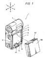
FIG. 1 is a perspective view showing the state immediately before a battery pack is loaded on a video camera according to the present invention. -
FIG. 2 is a front view of a battery loading portion seen from the right direction. -
FIG. 3 is an enlarged cross-sectional view of the battery loading portion taken along the line III-III inFIG. 2 . -
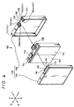
FIG. 4 is a perspective view of the battery pack that is exploded. -
FIG. 5 is a perspective view of the battery pack showing the whole thereof. -
FIG. 6 is a perspective view of the battery pack showing the whole thereof seen from the direction different from that ofFIG. 5 . -
FIG. 7 is an enlarged view of the battery pack seen from the upper direction after being exploded. -
FIG. 8 is an enlarged view of the battery pack seen from the upper direction. -
FIG. 9 is an enlarged diagram in which the portion of a battery side terminal is exploded, and respective portions are shifted in the upper and lower directions and are seen from the right direction. -
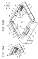
FIG. 10 is an enlarged perspective view of the battery loading portion, wherein (a) shows the state of a protection plate of the main body side terminal being rotated while (b) shows the state of the protection plate of the main body side terminal being not rotated. -
FIG. 11 is an enlarged perspective view of a lock mechanism that is in the state of being disassembled from the battery loading portion. -
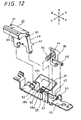
FIG. 12 is an enlarged perspective view of the lock mechanism after being disassembled. -
FIG. 13 is an enlarged diagram in which a portion of the appearance that the battery pack is loaded on or disengaged from the battery loading portion as in the cases ofFIGS. 14 through 16 is cut off and which is seen from the front direction, though this figure shows an initial loading stage. -
FIG. 14 is a diagram showing the battery pack in the halfway stage of being loaded. -
FIG. 15 is a diagram showing the battery pack in the finished stage of being loaded. -
FIG. 16 is a diagram showing the appearance of the battery pack being disengaged and a part of the battery pack being in the state of being floated by a jump-out-prevention lever. -
FIG. 17 is an enlarged view of the battery side terminal seen from the upper direction. -
FIG. 18 is an enlarged view of the battery side terminal seen from the left direction. -
FIG. 19 is an enlarged view of the battery side terminal seen from the back direction. -
FIG. 20 is an enlarged cross-sectional view of the battery side terminal taken along the line XX-XX inFIG. 18 . -
FIG. 21 is an enlarged cross-sectional view of the battery side terminal taken along the line XXI-XXI inFIG. 19 . -
FIG. 22 is an enlarged view of a main body side terminal seen from the left direction. -
FIG. 23 is an enlarged view of the main body side terminal seen from the lower direction. -
FIG. 24 is an enlarged cross-sectional view of the main body side terminal along the line XXIV-XXIV inFIG. 22 . -
FIG. 25 is an enlarged cross-sectional view of the main body side terminal along the line XXV-XXV inFIG. 22 . -
FIG. 26 is an enlarged cross-sectional view of a battery side terminal and the main body side terminal showing how the two join with each other, and this figure shows an initial joining stage in which a guide piece is in the state of being about to enter into a guide groove. -
FIG. 27 is a diagram showing the state in which a contact portion is about to contact with a contact piece in the halfway stage of joining. -
FIG. 28 is a diagram showing the finished state of joining. -
FIG. 29 is an enlarged cross-sectional diagram taken along the line XXIX- XXIX inFIG. 28 . -
FIG. 30 is an enlarged cross-sectional diagram taken along the line XXX- XXX inFIG. 28 -
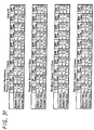
FIG. 31 , together withFIGS. 32 ,33 , shows the results of examining materials of a terminal piece and a terminal member as well as plating thereof, and this figure is a diagram showing result tables in relation to contact resistance. -
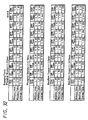
FIG. 32 is a diagram showing result tables in relation to engagement force. -
FIG. 33 is a diagram showing result tables in relation to disengagement force. -
FIG. 34 is an enlarged cross-sectional view of the contact portion in the state of being held between the contact pieces in the standard position. -
FIG. 35 is an enlarged cross-sectional view of the contact portion in the state of being held between the contact pieces in the position shifted in one direction. -
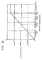
FIG. 36 is a graph showing the relationship between the amount of displacement of the contact piece and the contact pressure. -
FIG. 37 , together withFIGS. 38 to 40 , is a diagram for explaining whether or not loading is permitted based on the combination of plural kinds of discriminating tabs and the blocking portions, and this figure shows the relations between a blocking portion type I and respective discriminating tabs. -
FIG. 38 is a diagram showing the relations between a blocking potion typeII and the respective discriminating tabs. -
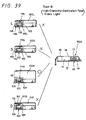
FIG. 39 is a diagram showing the relations between a blocking portion typeIII and the respective discriminating tabs. -
FIG. 40 is a diagram showing the relations between a blocking portion typeIV and the respective discriminating tabs. -
FIG. 41 is a perspective view of an essential portion showing a deformation example of a portion-to-be-locked in the battery pack. -
FIG. 42 is a perspective view of an essential portion showing another deformation example of the -to-be-locked in the battery pack. -
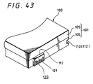
FIG. 43 is a perspective view of an essential portion showing further another deformation example of the in the battery pack. -
FIG. 44 is a perspective view of the battery pack of the present invention showing the state of the battery pack immediately before it is loaded on the battery loading portion of an electronic apparatus. -
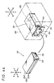
FIG. 45 , together withFIGS. 46 through 48 , is a perspective view of the battery pack for sequentially explaining the assembling thereof, and this figure shows the appearance of how the battery side terminal is attached to a substrate. -
FIG. 46 shows the appearance of how the substrate is soldered to a battery cell. -
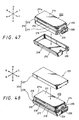
FIG. 47 shows the appearance of how the battery cell is housed in a lower surface case. -
FIG. 48 shows the appearance of how an upper surface case is made to join with the lower surface case. -
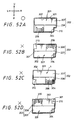
FIG. 49 is a horizontal cross-sectional view of the electronic apparatus showing the appearance of how it has been loaded, and this figure shows the state before the electronic apparatus is loaded. -
FIG. 50 shows the state in which the electronic apparatus is loaded. -
FIG. 51 is a longitudinal cross-sectional view of the battery pack. -
FIG. 52 is a front view of the battery pack and the battery loading portion for explaining the relations between the two, with the former having been loaded or about to be loaded on the latter. - Hereinafter, a method for preventing a component-to-be-loaded from being erroneously loaded on a main body side apparatus, a component-to-be-loaded and a battery pack will be explained in detail according to embodiments illustrated in the attached drawings.
- In addition, the embodiments shown in the drawings are such that the present invention is applied to the structure of how the battery pack is loaded in a video camera, wherein ┌video camera┘ corresponds to ┌main body side apparatus┘ described in the scope of claim, and ┌battery pack┘ corresponds to ┌component-to-be-loaded┘ described in the scope of claim, respectively. In addition, ┌video light┘, ┌battery charger┘ to be mentioned later on correspond to ┌main body side apparatus┘ , and ┌dry cell pack┘ corresponds to ┌component-to-be-loaded┘ described in the scope of claim, respectively.
- Further, a video camera to be explained in the following is a camera of the type which has a lens body tube positioned at its upper portion of the camera main body when it is in an ordinary state for use with a battery pack removably loaded on the right side surface. To this end, also in the following, an explanation will be given with this direction as a standard, which means that the U direction, the D direction, the L direction, the R direction, the F direction, the B direction which are each indicated by an arrow mark in each of the drawings respectively mean the upper direction, the lower direction, the left direction, the right direction, the front direction and the back direction. Furthermore, the orientation (directionality) of the battery pack is not originally unique, though in order to explain the case where the battery pack is to be loaded on the above-mentioned video camera, an explanation will be given of the battery pack with the same orientation (directionality).
- A
video camera 1 comprises a rectangular solid-like cameramain body 2, alens body tube 3 provided on the upper portion of the cameramain body 2, a display panel provided on the left surface of the camera main body 2 (not shown in figures) and the like. - In addition, on the right surface of the camera
main body 2 is provided abattery loading portion 10 that is surrounded by four frame bodies (afront frame body 11, aback frame body 12, anupper frame body 13, a lower frame body 14)(refer toFIGS. 1 and2 ). - The
battery loading portion 10 forms a rectangle when seen from the front, and is formed to be slightly larger than the front projection form of abattery pack 100. Further,small ribs front frame body 11 and an inner surface (front surface) 12a of theback frame body 12, though the amount of projections of the small ribs is small and the amount of projections is formed to be slightly larger as the ribs near toward thebottom surface 15 of the battery loading portion, that is, formed to taper off. The interval between thesmall ribs bottom surface 15 is formed to be approximately equal to or slightly smaller than the front and back, and width, dimensions of the battery pack (refer toFIG. 3 ). - On the
inner surface 13a side of the front portion of theupper frame body 13 constituting the battery loading portion, a terminal 30 (hereinafter referred to as ┌main body side terminal┘) is provided for connecting to a terminal (hereinafter referred to as ┌pack side terminal┘) 120 of the above-mentionedbattery pack 100, and alock mechanism 40 for holing thebattery pack 100 in thebattery loading portion 10 is provided at the center of the lower frame body 14 (refer toFIG. 1 ). - For a start, the
battery pack 100 to be used by thevideo camera 1 will be explained. - The
battery pack 100 includes a rectangular solid-like battery case 101,battery cells battery case 101, asubstrate 104 with anIC chip 103 mounted thereon for computing and storing a residual quantity of the battery pack and the like, and abattery side terminal 120 to be attached to thesubstrate 104 and for connecting to the main body side terminal 30 (refer toFIG. 4 ). - Here, the
battery pack 100 has plural kinds of battery packs mainly because capacities thereof are different, and those shown inFIG. 1 ,FIG. 3 andFIG. 9 ,FIG. 13 andFIG. 16 belong to the battery pack of the standard type that is the smallest (thin in thickness) in outward form of the plural kinds of the battery packs 100. - Then, the battery case is comprised of a
front surface case 105 and a back surface case 106 (refer toFIG. 4 ), and theback surface cases 106 are the same in size in plural numbers of the types of the battery packs 100, though thefront surface cases 105 are different in size (thickness) in the battery packs 100 (refer toFIGS. 37 through 40 ). - On the front portion of the upper surface of the
back surface case 106, a concave 107 that is a notch lower than the other portion is formed, and arectangular cutaway 108 that opens to the front surface side (right direction) and the back surface side (left direction) is formed at the concave 107, with the above-mentioned battery side terminal being slid from the front surface side (right direction) to be attached to therectangular cutaway 108. The upper surface of thebattery side terminal 120 that is attached to therectangular cutaway 108 is the same in height as the other portion except the concave 107 (refer toFIG. 9 ). - At the front and back side edges of the
rectangular cutaway 108 of theback surface case 106, ribs (hereinafter referred to as ┌terminal positioning rib┘) 109, 109 projected upward while extending in the right and left directions are respectively formed, and the left ends of theterminal positioning ribs back surface 106a of theback surface case 106 are formed at positions shifted slightly to the right direction from theback surface case 106a with the upper surface of these two terminal positioning ribs being the same in height as the other portion except the upper surface of the battery side terminal and the concave 107 of the back surface case 106 (refer toFIG. 7 ). - Further, the interval between the two
terminal positioning ribs battery side terminal 120, and the two terminal positioning ribs extend approximately in the right direction from the right side edge portion of the attached battery side terminal, and small projectingbars battery side terminal 120. Convex portions such as the small projectingbars terminal positioning ribs battery side terminal 120 are to serve as discriminatingtabs battery pack 100, which will be described later on (refer toFIG. 7 ). - A
right end portion 109a of the above-mentionedterminal positioning rib 109 overhang theback surface case 106 side when thefront surface case 105 is combined with theback surface case 106, and theright end portion 109a of theterminal positioning rib 109 becomes one of upper side portions-to-be- locked 112 when thebattery pack 100 is loaded on thebattery loading portion 10 of the cameramain body 2, which will be described later on (refer toFIG. 8 ). - At the back side corner portion of the upper surface of the
back surface case 106, a comparatively smallconcave portion 113 that opens to the upper and back directions, and such smallconcave portion 113 becomes one of the upper side portions-to-be locked 112 when thebattery pack 100 is loaded on the battery loading portion 10 (refer toFIG. 8 ). - Further, on a
lower surface 106b of theback surface case 106 is formed a concave bar groove-to-be-locked 114 extending in the front and back direction, which alock pawl 41 of therock mechanism 40 on themain camera body 2 side is to lock (to be described later on), and the groove-to-be-locked 114 serves as a lowerside locking portion 112 of the battery pack 100 (refer toFIG. 6 ). - In this manner, by providing the portions-to-be-locked 112 (the
right end portion 109a of the terminal positioning rib, theconcave portion 113 and the groove-to-be-locked 114) in various portions of the battery pack side in theback surface case 106, that is, one component, the accuracy of the position of thebattery pack 100 at a time of it being loaded on thebattery loading portion 10 can be improved (refer toFIG. 15 ). - Namely, loading of the
battery pack 100 on thebattery loading portion 10 is performed as theback surface 106a (left surface) of theback surface case 106 comes in contact with a bottom surface 15 (refer toFIG. 15 ), and at the same time, as the portions-to-be-locked 112 in various potions of the battery pack side (theright end portion 109a of the terminal positioning rib, theconcave portion 113 and the locked groove 114) become locked by corresponding locking portions (overhang portion 17 to be described later on, a smallconvex portion 20, the lock pawl 41) of thebattery loading portion 10 side. If the plurality of portions-to-be-locked 112, 112, ···· are provided in different component such as in, for example, theback surface case 106 and thefront surface case 105, when theback surface case 106 and thefront surface case 105 are assembled inaccurately, there occurs play in the locking state as well as a problem with the coupling state between the battery side terminal and the mainbody side terminal 30. - Then, with formation of the above-mentioned portions-to-be-locked 112 for positioning concentrated in one part (back surface case 106) as in the case of the
battery pack 100, the accuracy of the position of thebattery pack 100 in its loaded state can be improved, which makes it possible for the accuracy of the coupling between theback surface case 106 and thefront surface case 105 to be not so precise. - In addition, in the region that is an upper front portion of the
front surface case 105 and corresponds to the above-mentionedbattery side terminal 120, arecess portion 115 that is approximately the same in height as theconcave portion 107 of theback surface case 106 is formed, and at the left side edge of therecess portion 115, there is formed a terminalpressing rib 116 for pressing thebattery side terminal 120 from the right direction (refer toFIGS. 7 through 9 ). - The length in the front and back direction of the terminal
pressing rib 116 is formed to be approximately the same as the interval between the twoterminal positioning ribs surface case 106, that is, almost the same as the dimension in the front and back direction of thebattery side terminal 120, and as a result, when thefront surface case 105 is assembled to theback surface case 106, theterminal pressing rib 116 is positioned between the above-mentionedterminal positioning ribs battery side terminal 120 from the left direction, with the twoterminal positioning ribs back surface case 106 slightly projected more rightward than the terminalpressing rib 116 serving as the portions-to-be-locked 112, 112 (refer toFIG. 8 ). - With the
battery pack 100 of a standard capacity type, two rectangular-solid-like battery cells substrate 104 is attached on the upper portion thereof, with the above-mentionedbattery side terminal 120 mounted on the front portion and the above-mentionedIC chip 103 mounted on the back portion, of the substrate 104 (refer toFIG. 4 ). - In this manner, since the
battery side terminal 130 is provided at a position shifted in one direction with respect to thebattery pack 100, it becomes possible to provide a comparatively large space at a portion on the opposite side thereof, which makes it possible to arrange therein electronic portions such as theIC chip 103 and the like to thereby improve efficient use of the space. Specifically, when the rectangular- solid-like battery cells 102 are arranged in thebattery case 101, there occurs no dead space, so that thebattery cells battery pack 100. Though it is difficult to secure a space to arrange thebattery side terminal 120, theIC chip 103 on thesubstrate 104 and the like which jut out from the battery cell, effective use of the space can be carried out by arranging thebattery side terminal 120 at the shifted position with respect to thebattery pack 100 as mentioned above (refer toFIGS. 4 and7 ). - In addition, since the
battery side terminal 120 is provided at the shifted position with respect to the battery pack, erroneous loading of thebattery pack 100 on the cameramain body 2 can be prevented. - Meanwhile, detailed forms of the
battery side terminal 120 and therectangular cutaway 108 that is a receiving side of thebattery side terminal 120 and the method of assembling the both will be described in detail later on. - Next, the
battery loading portion 10 of the cameramain body 2 will be explained in detail. - The dimension of the
battery loading portion 10 of the cameramain body 2 from the top to the bottom is formed to be slightly larger than the thickness (thickness in the left and right direction) of theback surface case 106 of the above-mentionedbattery case 101. As a result, in the state in which thebattery pack 100 is loaded on thebattery loading portion 10, theback surface case 106 is positioned inside thebattery loading portion 10, and almost all the portion of thefront surface case 105 juts out from the camera main body 2 (refer toFIGS. 3 and15 ). - A main
body side terminal 30 is provided at a position opposed to the above-mentioned mainbody side terminal 120, that is, the corner portion between the inner surface (lower surface) of theupper frame body 13 and thebottom surface 15, or a position on the diagonally upper front side (refer toFIG. 10 ). - In a region corresponding to the position where the above-mentioned main
body side terminal 30 is provided, the region being an opening side edge (right side edge) of aninner surface 13a of theupper frame body 13, anover-hang portion 17 projecting in the lower direction is formed, with the dimension between theover-hang portion 17 and thebottom surface 15 of thebattery loading portion 10 being formed to be the same as that between theback surface 106a of the above-mentioned backsurface case 106 and the right end portion of the terminal positioning rib 109 (refer toFIG. 15 ) - As a result, when the
battery pack 100 is loaded on thebattery loading portion 10, and theright end portion 109a of theterminal positioning rib 109 is locked by theover-hang portion 17, there is no play between the two. Consequently, it is possible for locking to be carried out in the state in which no play occurs in the region on the front side of the upper portion of the battery pack 100 (refer toFIG. 15 ). - From the back portion of the
over-hang portion 17 toward thebottom surface 15 of the battery loading portion 10 (left direction) a projecting bar (hereinafter referred to as ┌a blocking projecting bar┘) 18 is integrally formed, and the tip portion of theblocking projecting bar 18 extends to a position properly apart from the bottom surface 15 (refer toFIG. 10 ) so that it does not interfere with the above-mentioneddiscriminating tab 111 of theback surface case 106 of the above-mentionedbattery pack 100. - Such
blocking projecting bar 18 and a small projectingportion 18a in the vicinity of the mainbody side terminal 30 to be described later on serve as a blockingportion 19 for determining whether or not thebattery pack 100 is to be loaded. Meanwhile, since the above-mentionedblocking portion 19 is made not to interfere with the discriminatingtab 111 of thebattery pack 100, loading of thebattery pack 100 on thebattery loading portion 10 is permitted, though in an apparatus, for example, a video light 150 (thebattery pack 100 with low capacity is not to be loaded thereon) for loadingsuch battery pack 100, there is a case where loading of the battery pack is not permitted due to difference in capacity of thebattery pack 100. - On an occasion such as this, it is designed such that the above-mentioned
blocking portion 19 extends in the vicinity of thebottom surface 16 of thebattery loading portion 10 to thereby interfere with the above-mentioneddiscriminating tab 111, with the result that loading of thebattery pack 100 is blocked. Whether or not to permit loading ofsuch battery pack 100 is exercised based on the forms of and positional relations between the discriminatingtab 111 of the above-mentionedbattery pack 100 side and the above-mentionedblocking portion 19, which will be described in detail later on. - At a position corresponding to the small
convex portion 113 of the above-mentioned backsurface case 106, the position being a corner portion between the back side of the inner surface (lower surface) 13a of theupper frame body 13 of thebattery loading portion 10 and an inner surface (front surface) 12a of theback frame body 12 is formed a smallconvex portion 20 that exactly engages with the small concave portion 113 (refer toFIG. 10 ), and the position at which the smallconvex portion 20 is formed from thebottom surface 15 of the battery loading portion coincides with the position at which the above-mentioned smallconcave portion 113 is formed from theback surface 106a of theback surface case 106. As a result, when thebattery pack 100 is loaded on thebattery loading portion 10, locking of the battery pack in the back side region of the upper portion is performed without any play. - A rectangular aperture (hereinafter referred to as ┌a push-up plate disposition aperture┘) 21 is formed at the lower center of the
bottom surface 15 of thebattery loading portion 10, and there is provided a cutaway portion (hereinafter referred to as ┌a lock lever disposition aperture┘) 22 continuing from the above-mentioned push-upplate disposition aperture 21 on the inner surface (upper surface) of the lower frame body 14 (refer toFIG. 2 ). - The
lock mechanism 40 comprises alock lever 42 having thelock pawl 41 that engages with the groove-to-be-locked 114 formed on the lower surface of thebattery pack 100, a push-upplate 43 for pressing abottom surface 106a of thebattery pack 100 in the direction in which is disengaged, a jump-out prevention lever 44 for preventing thebattery pack 100 from jumping out when locking is released by the above-mentionedlock lever 42, and theselock lever 42, push-upplate 43 and jump-out prevention lever 44 are rotatably supported on the same shaft by abase plate 45 on the inside of the corner portion between thelower frame body 14 and the bottom surface 15 (refer toFIGS. 11 and12 ). - Then, the
base plate 45 is housed inside of and fixed to thelower frame body 14, and the above-mentionedlock lever 42 is disposed in an above-mentioned locklever disposing aperture 22 of thelower frame body 14, the push-upplate 43 in a push-upplate disposition aperture 21, the jump-out protection lever 44 in a rectangular-like cutaway (hereinafter refer to as ┌jump-out protection lever disposing aperture┘) 46 that is formed continuous from theaperture 22, respectively (refer toFIG. 11 ). - In addition, a
coil portion 48a of ahelical torsion spring 48 is fit around arotation shaft 47 that rotatably supports thelock lever 42, the push-upplate 43 and the jump-out protection lever 44, with onearm portion 48b acting on thelock lever 42 and the other arm portion 48c acting on the push-upplate 43 to thereby rotatably urge thelock lever 42 in the upward direction and urge the push-upplate 43 in the right direction (refer toFIG. 12 ). - The
lock lever 42 lends itself an appearance such that the whole thereof is an L-letter lying on its side, with anupper surface piece 49 being formed to become a portion of the inner surface (upper surface) of the above-mentionedlower frame body 14, a cross-sectional triangle-like lock pawl 41 being formed in the front and back direction, extending to a position that is shifted to the center of rotation of theupper surface piece 49, and anoperation portion 50 being formed at the lower portion of the right side surface for operating the lock lever 42 (refer toFIGS. 11 and12 ). - Then, the
lock pawl 41 is formed such that it is slightly shifted in the right direction (front side) from thebottom surface 15 of thebattery loading portion 10, with the distance from thebottom surface 15 being equal to the distance from thebottom surface 106a of the groove-to-be-locked 114 of the above-mentionedbattery pack 100 so that thebattery pack 100 is resultantly pressed against thebottom surface 15 of thebattery loading portion 10 when thelock pawl 41 engages with the groove-to-be-locked 114 (refer toFIG. 15 ). - In addition, on both the left and right side portions of the
upper surface piece 42 of thelock lever 42 there are respectively formedsmall projections lever disposing aperture 22 of thelower frame body 14, and with theprojections lever disposing aperture 22, rotational urging by the above-mentionedhelical torsion spring 48 is blocked. In such a state the upper surface of theupper surface piece 49 is flush with the upper surface of thelower frame body 14. - The push-up
plate 43 hassmall pieces small pieces base plate 45, rotational urging by the above-mentionedhelical torsion spring 48 is blocked. In such a state the push-upplate 43 is in the state of projecting in the right direction from the push-up plate disposition aperture 21 (refer toFIG. 12 ). - The jump-
out prevention lever 44 has ahelical compression spring 54 provided in compressed form between the lower surface of a rotational end portion and a protrudingpiece 53, and the jump-out prevention lever 44 is thereby rotatably urged in the upper direction like the above-mentionedlock lever 42 is (refer toFIGS. 13 through 16 ). By the way, inFIGS. 13 through 16 , the above-mentionedbattery side terminal 120 and the mainbody side terminal 30 are omitted. - The jump-
out prevention lever 44 has apawl portion 55 formed at the rotational end, that projects in the upper direction, and there is integrally formed arotation blocking piece 56 at the base end portion thereof, that projects in the forward direction. With the collision of therotation blocking piece 56 with a restrainingpiece 57 formed in thebase plate 45, rotational urging by the above-mentionedhelical compression spring 54 is blocked. In such a state, the above-mentionedpawl portion 55 projects in the upper direction from the upper surface of the lower frame body 14 (refer toFIGS. 13 through 16 ). - In addition, the
pawl portion 55 of the jump-out prevention lever 44 is formed more rightward than thelock pawl 41 of the lock lever 42 (refer toFIGS. 13 through 16 ). - In this manner, when the
battery pack 100 is not in the state of being loaded on thebattery loading portion 10, thelock pawl 41 of thelock lever 42 and thelock portion 55 of the jump-out prevention lever 44 projects in the upper direction from the upper surface of thelower frame body 14, and the push-upplate 43 is in the state of projecting in the right direction from the bottom surface of the battery loading portion 10 (refer toFIG. 13 orFIG. 16 ). - Then, when the
battery pack 100 is about to be loaded on thebattery loading portion 10, a procedure will be carried out in the following manner, and the loadedbattery pack 100 is held in a locked state within thebattery loading portion 10 by the above-mentioned lock mechanism. - First of all, the
battery pack 100 is inserted in thebattery loading portion 10 with the upper portion thereof being tilted, and the battery side terminal 120 (including theterminal positioning rib 109 of theback surface case 105 and the terminalpressing rib 116 of the front surface case 105) is slid into the inside of theover-hang portion 17 of thebattery loading portion 10. Then as mentioned before, since the discriminatingtab 111 on the side of thebattery pack 100 does not interfere with the member (blocking portion 19) on the side of thebattery pack 100, thebattery side terminal 120, theterminal positioning rib 109 and the terminalpressing rib 116, of thebattery pack 100 can be slid deep into the over-hang portion 17 (refer toFIG. 13 ). - At this time,
terminal members battery side terminal 120 and threeterminal pieces body side terminal 30, not shown, are separately joined with each other. - In addition, as will be described in detail later on, by having the discriminating
tab 111 on the side of thebattery pack 100 and the blockingportion 19 on the side of thebattery loading portion 10 formed so as to interfere with each other, the above-mentionedbattery side terminal 120 can not be slid deep into theover-hang portion 17 of thebattery loading portion 10. Therefore, theterminal member 122 of thebattery side terminal 120 and theterminal piece 31 of the mainbody side terminal 30 are intended not to join with each other. - Moreover, if the
battery pack 100 is forced to be loaded on thebattery loading portion 10 even when the blockingportion 19 of theloading portion 10 and the discriminatingtab 111 of thebattery pack 100 interfere with each other, there will be a remote possibility in which the battery pack can be loaded thereon as a result of bending of theupper frame body 13 of thebattery loading portion 10 as the above-mentioneddiscriminating tab 111 presses the blockingportion 19. - On such an occasion, however, since the blocking
portion 19 and the discriminatingtab 111 are formed in the vicinity of both theterminals body side terminal 30 retreats in the direction toward which it is pressed, with the result that both of the terminals do not join with each other. Consequently, theterminal piece 31 and theterminal member 122 do not come in contact with each other and thereby the electric contact can be avoided. - Next, with the upper portion of the battery pack 100 (the portion of the
battery side terminal 120, which is locked by the over-hang portion 17) as a rotation fulcrum, the lower portion of thebattery pack 100 is rotated leftward so that it is loaded on the battery loading portion 10 (refer toFIGS. 14 and15 ). - At this time, after the
pawl portion 55 of the jump-out protection lever 44 of the above-mentionedlock mechanism 40 is kicked downward by the lower left side of thebattery pack 100, thepawl portion 55 engages with the groove-to-be-locked 114 (refer toFIG. 14 ). - Further, as the lower portion of the
battery pack 100 is pressed against thebattery pack 100, thepawl portion 55 of the above-mentioned jump-out prevention lever 44 is kicked by the edge portion of the groove-to-be-locked 114 and at the same time, thelock pawl 41 of thelock lever 42 is kicked by the lower left side edge portion (bottom surface side corner portion) and then, thelock pawl 41 engages with the groove-to-be-locked 114 to thereby complete loading of the battery pack 100 (refer toFIG. 15 ). - In addition, prior to the
lock pawl 41 engaging with the groove-to-be-locked 114, thelower surface 106a of thebattery pack 100 rotates the push-upplate 43 in the left direction so that thelower surface 106a of thebattery pack 100 is to approximately contact face to face with thelower surface 15 of the battery loading portion 10 (refer toFIG. 15 ). - Then, the rotations of these
lock lever 42, jump-out protection lever 44 and push-upplate 43 are performed against the spring force of the above-mentionedhelical torsion spring 48 orhelical compression spring 54. - At this time the
terminal member 122 of thebattery side terminal 120 joins with theterminal piece 31 of the mainbody side terminal 30 and at the same time, theright end portion 109a (portion-to-be-locked 112) of theterminal positioning rib 109 provided on the upper portion of thebattery pack 100 engages with theover-hang portion 17, with the concave portion 113 (portion-to-be-locked 112) of thebattery pack 100 engaging with the smallconvex portion 20 of thebattery loading portion 10. - As a result, on the upper portion of the
battery pack 100, theright end portion 109a (portion-to-be-locked 112) of theterminal positioning rib 109 and theover-hang portion 17, and the small concave portion 113 (portion-to-be-locked 112) and the smallconvex portion 20 engage, with each other, respectively while thelock pawl 41 and the groove-to-be-locked 114 engage with each other at the lower portion of thebattery pack 100 so that thebattery pack 100 is held in the battery loading portion 10 (refer toFIG. 15 ). - The
lock pawl 41 of thelock lever 42 and thepawl portion 55 of the jump-out protection lever 44 press thebattery pack 100 in the upward direction to thereby press thebattery pack 100 against theupper frame body 13 so that positioning thereof in the up and down direction is performed (refer toFIG. 15 ). - As a result, the
battery side terminal 120 is pressed against the mainbody side terminal 30 so that the stable joining state between theterminal member 122 andterminal piece 31 is maintained. Particularly, thebattery side terminal 120 and the mainbody side terminal 30 are provided at positions shifted in the forward direction relative to thebattery pack 100 and also, since the jump-out prevention lever 44 is provided at a position shifted in the forward direction from the middle portion of the front and back direction, that is, the jump-out prevention lever 44 is provided at a position opposed to both theterminals battery pack 100 is pressed upward by thepawl portion 55 so that the stable joining state between theterminal member 122 and theterminal piece 31 can be ensured (refer toFIG. 2 ). - Further, since the
battery pack 100 has the lower portion thereof pressed in the right direction by the push-upplate 43, which is to be blocked by the engagement between thelock 41 and the groove-to-be-locked 114, positioning in the loading direction (left and right direction) of thebattery pack 100 is performed and furthermore, since thebattery pack 100 is regulated by thesmall ribs front frame body 11, and on the inner surface (front surface) 12a of theback frame body 12, positioning thereof in the front and back direction is performed (refer toFIG. 3 ). - The
battery pack 100 having been loaded on thebattery loading portion 10 of the cameramain body 2 in such a manner will be unloaded in the following way. - That is, first of all, lock disengagement of the lock mechanism by pressing the
operation portion 50 by hand or finger is performed (refer toFIG. 16 .). - When the
lock lever 42 is operated, it is rotated in the lower direction against the spring force of thehelical torsion spring 48 and thereby disengaged from the groove-to-be-locked 114 of thebattery pack 100. - When the
lock pawl 41 is disengaged from thebattery pack 100, the lower portion of thebattery pack 100 is pressed in the left direction by the push-upplate 43 and lifts from thebottom surface 15 of the battery loading portion 10 (refer toFIG. 16 ). - At this time, when the lower portion of the
battery pack 100 slightly floats from thebottom surface 15, thepawl portion 55 of the jump-out prevention lever 44 engages with the groove-to-be-locked 114. As a result, although thebattery pack 100 floats from thebattery loading portion 10, since thepawl portion 55 of the jump-out prevention lever 44 is caught by the groove-to-be-locked 114, thebattery pack 100 does not jump out inadvertently. Particularly, when thevideo camera 1 is oriented in the above-mentioned direction (direction in which shooting ordinarily is performed), even if the locking of thebattery pack 100 is disengaged, thepawl portion 55 of the jump-out prevention lever 44 is caught by the groove-to-be-locked 114 so that thebattery pack 100 is not disengaged from thebattery loading portion 10, with the result that thebattery pack 100 can be prevented from dropping therefrom. - Next, by having the
battery pack 100 whose lower portion is lifting gripped and pulled out by hand in the direction in which it is being disengaged (right direction), thebattery pack 100 is easily disengaged from thebattery loading portion 10 because of disengagement between thepawl portion 55 of the jump-out prevention lever 44 and the groove-to-be-locked 114. - Next, the
battery side terminal 120 and how it is assembled to thebattery pack 100 will be explained in detail. - As mentioned above, the
battery side terminal 120 is comprised of aterminal case 121 and theterminal members terminal case 122 lends itself a flat cubic solid block-like appearance with fivegrooves FIGS. 17 through 19 ). - Of the above-mentioned five grooves, two
grooves grooves grooves FIGS. 17 through 19 ). - In addition, the median three
grooves terminal disposition grooves contact pieces 125 being arranged to face each other in each of thegrooves 124, and ahousing space 126 for housing the above-mentionedcontact pieces terminal disposition grooves FIGS. 17 and 18 ). By the way, only oneterminal member 122 is illustrated by broken line inFIG. 17 and FIG. 18 , and the other twoterminal members - Further, chamfering process such as an R corner, taper corner or the like have are applied to the opening side edges of these
guide grooves terminal disposition grooves pieces body side terminal 30 and theterminal pieces respective grooves FIGS. 26 through 28 ). - The respective
terminal members 122 of thebattery side terminal 120 are integrally formed of thecontact pieces base piece 127 connecting onecontact piece 125 with the other 125, and alead piece 128 that is soldered to thesubstrate 104 arranged in thebattery case 101 and extends from thebase piece 127 in the direction opposite to thecontact pieces 125, 125(refer toFIGS. 21 and 22 ). - The
contact pieces terminal case 121, and hemispherical contactconvex portions convex portions 123a, 125a being in the state of contacting with each other without pressure being applied to the both (so-called zero-contact state). When theterminal disposition grooves battery side terminal 120 are looked at, only the two contactconvex portions FIGS. 20 and21 ) . - Therefore, when a
contact portion 35 is inserted in theterminal disposition groove 124, it contacts with only the contactconvex portions contact portion 35 is inserted in theterminal disposition groove 124, since the spring characteristics of thecontact pieces terminals battery pack 100 on thevideo camera 1 in the above-mentioned embodiments. - The
base piece 127 is exposed at a position where it is attached to the right side surface of theterminal case 121, and thelead piece 128 is bent at right angles and extended in the right direction from the lower edge of thebase piece 127 to be approximately flush with abottom surface 121a of the terminal case 121 (refer toFIGS. 20 and21 ). - On the front and back both side surfaces of the
terminal case 121 are formed slideconvex portions convex portions rectangular cutaway 108 of the above-mentioned backsurface case 106 and slide-engage withslide grooves terminal positioning rib 109 so that thebattery side terminal 120 is supported to the back surface case 106 (refer toFIG. 9 ). - The left ends of the
slide grooves back surface case 106 are blocked up so that leftward positioning of thebattery side terminal 120 is performed when it is slide-engaged therewith. That is to say, the position from theback surface 106a of theback surface case 106 to the battery side terminal is regulated. - There are formed cut
grooves convex portions cut grooves projections FIG. 9 ). - Then, such
battery side terminal 120 has threelead pieces substrate 104 and mounted on the front side corner portion of the substrate 104 (refer toFIGS. 4 and7 ). In addition, electronic portions such as anIC chip 103 and the like are mounted on backside predetermined positions of thesubstrate 104, where thebattery side terminal 120 is not mounted on (refer toFIG. 7 ). - Therefore, the
battery cells substrate 104 on which the above-mentionedbattery side terminal 120,IC chip 103 and the like have been mounted is attached on the upper portion of thebattery cells 102, 102 (refer toFIG. 4 ). - Next, the
battery cells such substrate 104 had been attached is inserted in theback surface case 106 from the right direction thereof. At this time, thebattery side terminal 120 is slide-inserted in therectangular cutaway 108 of theback surface case 106 from the right direction (refer toFIG. 7 ). - Then, as mentioned above, the slide
convex portions battery side terminal 120 are inserted in theslide grooves FIG. 7 ). - Finally, both are combined with each other by joining the
front surface case 105 with theback surface case 106 to thereby cover the battery cells 102 (refer toFIG. 8 ). - At this time, the
projections front case 105 are engaged with thecut grooves back surface case 106, and at the same time, theterminal pressing rib 116 presses the right surface of theterminal case 121 to thereby cover thebase pieces terminal member 122, which are exposed from the right surface thereof. Then, positioning in the left and right direction of thebattery terminal 120 is performed with thebattery terminal 120 held between theback surface case 106 and thefront surface case 105. - The combination of the
front surface case 105 and theback surface case 106 is performed in the state in which the opening peripheral edges of the both are joined with each other by ultrasonic welding. In addition, the both may be bonded with each other with adhesives instead of ultrasonic welding. - As just described, the
battery pack 100 can be composed of three portions in such a manner that theback surface case 106, the battery cell 102 (including thebattery side terminal 120, thesubstrate 104 and the like), thefront surface case 105 are assembled thereto from one direction. - Next, the combination of the main
body side terminal 30 and the above-mentionedbattery side terminal 120 will be explained in detail. - First of all, the main
body side terminal 30 is provided at the above-mentioned position (front portion bottom surface side corner), and comprises threeterminal pieces bottom surface 15 and theinner surface 13a of theupper frame body 13, the twoguide pieces terminal pieces upper frame body 13 so as to cover the upper space of the respectiveterminal pieces FIGS. 22 and23 ). - The
terminal piece 31 is a rectangular flat plate seen from the front and back direction with the upper edge and left edge thereof being embedded in theupper frame body 13, and alead portion 34 is provided to project from the upper frame body 13 (refer toFIG. 24 ), the portion (down edge and right edge) exposed from theupper frame body 13 serving as thecontact portion 35 held between thecontact pieces battery side terminal 120, and the end side edge thereof have been chamfered. - Three of the
terminal pieces terminal disposition grooves battery side terminal 120, and the thickness of each of theterminal piece 31 is formed into approximately a half of the width of theterminal disposition groove 124 formed in the above-mentioned battery side terminal 120 (refer toFIGS. 22 and23 ). - The
guide piece 32 is of a rectangular shape similar to that of the above-mentionedterminal piece 31 when seen from the front and back direction, and is integrally formed together with theupper frame body 13 and thebottom surface 15 of the battery loading portion (refer toFIG. 24 ). - In addition, the
guide terminals contact portion 35 of theterminal piece 31 when seen from the front and back direction, and the plate thickness thereof is formed to be thicker than theterminal piece 31. Further, theguide terminals guide grooves battery terminal 120, and the plate thickness of each of theguide pieces guide grooves terminal case 121 of the above-mentionedbattery side terminal 120 with the end side edge thereof being chamfered (refer toFIG. 23 ). - As described above, since the
guide piece 32 is formed to be larger than thecontact portion 35 of theterminal piece 31, when the mainbody side terminal 30 is about to be combined with thebattery side terminal 120, the guide is made to enter into theguide groove 123 of theguide piece 32 earlier than thecontact portion 35 enters into the terminal groove 124 (refer toFIG. 26 ). - The
protection plate 33 is supported to the position closer to the opening side edge (right side edge) of the front end portion of the inner surface (undersurface) of theupper frame body 13 for freely rotating in the up and down direction (refer toFIGS. 24 and25 ). - To be concrete, at the front end portion of the inner surface (lower surface) of the
upper frame body 13 is formed a convex-likeprotection frame housing 13b, and at the front and back both side edges of theprotection plate 33 are integrally formed supportshaft projecting portions plate housing portion 13b, and acoil spring 37 is arranged around the front side supportshaft projecting portion 36. Theprotection plate 33 is urged in the counterclockwise direction when seen from the backward direction (refer toFIGS. 24 and25 ). - At a rotation fulcrum portion of the
protection plate 33 are providedrotation blocking portions 38, 38 (only one is shown in the figures) that are in contact with theupper frame body 13 for blocking the above-mentioned counterclockwise rotation, and the protection plate becomes a rotational end of the counterclockwise direction side thereof when the rotational end thereof is oriented in the left oblique downward direction (substantially 45° degrees) (refer toFIGS. 10(a) ,24 , and29 ). In addition, the rotational end of the clockwise direction side of theprotection plate 33 is at a position where it is housed in the protectionplate housing portion 13b of theupper frame body 13, or approximately in a horizontal position (refer toFIG. 10(b) ). - The
protection plate 33 in the front and back direction is slightly smaller in size than the distance between the above-mentioned twoguide pieces guide pieces terminal piece 31 are formedslits protection plate 33 is rotated upward, the respectiveterminal pieces slits protection plate 33 to rotate, with theterminal pieces FIGS. 10 ,22 , and23 ). By the way,FIG. 10(a) shows the state in which the protection plate has been rotated, andFIG. 10(b) shows the state in which the protection plate is not rotated. - Then, when external force is not applied to the
protection plate 33, at the rotational end in the counterclockwise direction of theprotection plate 33, the corner portions between the twoguide pieces FIG. 25 ). In addition, in this state, the corners of thecontact portions respective terminals slits FIG. 25 ). - Then, as will be described later in detail, when the
battery pack 100 is loaded on thebattery loading portion 10, theterminal case 121 of thebattery side terminal 120 presses the above-mentionedprotection plate 33 to thereby rotate in the clockwise direction against the spring force of thehelical torsion spring 37 and ends up being positioned in the protectionplate housing portion 13b of the upper frame body 13 (refer toFIG. 29 ). - As a result, the
contact portions 35. 35. 35 of themain body terminal 30 are exposed and enter relatively into theterminal disposition grooves terminal case 121 to thereby be held between the pair ofcontact pieces FIG. 28 ). - In this manner, when the
protection plate 33 is in the state in which it is not subjected to external force, since theprotection plate 33 is in the state of covering thecontact portions FIG. 25 ). - In addition, when any kind of collision occurs on the portion of the
main body terminal 30, for example, such as when thebattery pack 100 is loaded in a wrong orientation (erroneous loading), there is a possibility that a member other than thebattery terminal 120 may collide with the mainbody side terminal 30. - Even on such an occasion, since the
guide pieces contact portions guide pieces contact portions contact portions - Further, when comparatively small foreign materials collide with the main
body side terminal 30, since they collide with theprotection plate 33 prior to colliding with the terminal piece 31 (contact portion 35) due to the presence of the above-mentionedprotection plate 33, the external force is alleviated so that thecontact portion 35 is not directly subjected to large external force. - Furthermore, as described above, since the
protection plate 33 is provided in the state of being held between the twoguide pieces protection plate 33, since theguide pieces protection plate 33, and further, since, as described above, the three respective contact portions are inserted in theslits contact portions respective slits protection plate 33. Consequently, since the external force never acts on the onecontact portion 35, it is possible in this regard to prevent thecontact portions - By the way, as in the above-mentioned embodiment, such main
body side terminal 30 may haveguide pieces terminal pieces protection plate 33 rotatably provided, or may have respective portions molded or formed as another member in a base member of a predetermined form to thereby attach such member to theupper frame body 13 as a terminal. - Next, how the
battery side terminal 120 is connected to the mainbody side terminal 30 when thebattery pack 100 is loaded on thebattery loading portion 10 will be explained. - First of all, the
battery pack 100 has the battery side terminal 120 (including theterminal positioning rib 109, the terminal pressing rib 116) obliquely positioned so as to dive under theover-hang portion 17 of theupper frame body 13 so that the mainbody side terminal 30 and thebattery side terminal 120 are opposed to each other. - Next, when the
battery side terminal 120 is made to dive under the above-mentioned over-hang portion 17 (refer toFIG. 13 ), theguide pieces body side terminal 30 are relatively inserted in theguide grooves FIG. 26 ). At this time, since theguide grooves guide pieces - In such a condition, the
guide pieces guide grooves battery terminal 120 relative to themain body terminal 30 is performed. As mentioned above, prior to thecontact pieces contact portions guide pieces guide grooves terminals contact pieces contact portion 35 of both the terminal 120, 30 come in contact with each other, with the result that the contact to be made later on between thecontact pieces contact portion 35 is performed with high precision. - From this state, the lower portion of the
battery pack 100 is rotated and then is loaded on thebattery loading portion 10. The rotation of thebattery pack 100 is performed by having the portion-to-be-locked of theback surface case 106 caught by the above-mentionedover-hang portion 17 with the region as rotational fulcrum (refer toFIG. 14 ). - Then, the
contact portion 35 of themain side terminal 30 relatively enters into theterminal disposition groove 124 of the battery side terminal 120 (refer toFIG. 27 ), and contacts with and push aside the two contactconvex portions contact pieces contact portions 35. As a result, an electric connection between thebattery side terminal 120 and the mainbody side terminal 30 is established (refer toFIG. 28 ). - In addition, the relations between the
contact portion 35 and thecontact pieces contact portion 35 relatively moves in the surface direction thereof, and since the twocontact pieces convex portions contact portion 35 and thecontact pieces - Further, since the relations between the
battery side terminal 120 and the mainbody side terminal 30 are such that theterminal disposition groove battery side terminal 120 contact with the flat plate-like contact portions battery side terminal 120 can be possibly combined with the mainbody side terminal 30 from directions in the range of 90° degrees including the right and left direction and the up and down direction. - That is, when the structures of only the
battery side terminal 120 and themain body side 30 are taken into consideration, thebattery side terminal 120 can be combined with the mainbody side terminal 30 from the left direction or the downward direction, or from the left oblique downward direction including the just-mentioned directions, meaning that the former can be combined with the latter from any of directions in the range of substantially 90° degrees, and further, in any of the combinations from whichever of these directions, unreasonable force never acts on either of thecontact portion 35 and thecontact pieces contact portion 35 and thecontact pieces - Of course, in the relations between the above-mentioned
battery pack 100 and thebattery loading portion 10 of the cameramain body 2, since thebattery side terminal 120 is so intended to combine with the mainbody side terminal 30 from the substantially left direction, it may be said that the structures of thebattery side terminal 120 and the mainbody side terminal 30 can not be fully brought into play. - However, since loading of the above-mentioned
battery pack 100 on thebattery loading portion 10 is performed by rotation, and therefore, the combination of both theterminals contact portion 35 and thecontact pieces terminals - In addition, since the contact
convex portions contact pieces convex portions contact portion 35, there is a further possibility that both the terminals are combined with each other in the range of 90° degrees including the above-mentioned two directions. - That is, the
contact portion 35 enters to push aside thecontact pieces contact portion 35 contacts with only the contactconvex portions battery loading portion 10 can receive thebattery pack 100 in the same manner in any of the combinations of both theterminals - Further, since the contact
convex portions contact pieces contact pieces contact portion 35 are slightly shifted, it is possible to maintain the stable state of the connection between the two terminals (contact piece - Next, the quality of material and the width of the
terminal member 122 that affect the state of contact between thecontact pieces contact portion 35 relating to the combination of both theterminals - In addition, the
terminal piece 31 is made of brass (thickness: t = 0.35 mm), and the contact portion thereof is gilded 0. 76µm in thickness. Further, the reason why brass is chosen as the material for theterminal piece 31 is because brass, phosphor bronze and Beryllium copper are generally used as a point of contact, and costs and workability are also taken into consideration. - Furthermore, with respect to gilding, a Nickel layer is used as a base sheet, and 0.75 in thickness is set with an eye to increasing a safety ratio because, when the state of use of the
battery pack 100 and thevideo camera 1 is taken into consideration, repeated insertion and pulling-out of thebattery pack 100 are frequently performed. - Consequently, even if applied to the terminal structures of the
video camera 1 and thebattery pack 100, the contactconvex portions - In addition, the layer thickness of 0.76µm in gilding is mainly for contact portions, that is, the
contact portion 35, though a layer thickness of not more than 0.1 µm in gilding is recommended for thelead portion 34. That is for ensuring an electric connection stability of the both. - Then, as for the
terminal member 122, one is chosen out of four samples after testing of them. As materials for such tests, as mentioned above, three materials (brass, phosphor bronze, Beryllium copper) had been considered, but by taking into consideration the spring force of thecontact pieces - A
sample ① used phosphor bronze (thickness : t=0.2µ mm) as material with 0.76µm thick gilding being applied to a contact portion, asample ② used phosphor bronze (thickness : t=0.2 mm) as material with 0.76 µm thick gilding being applied to a contact portion, a sample③ used Beryllium copper (thickness : t=0.2 mm) as material with 0.76 thick gilding being applied a contact portion, and a sample ④ used Beryllium copper (thickness : t=0.15mm) as material, and a sample ④ used Beryllium copper (thickness : t=0.15mm) as material with 0.76 thick gilding being applied to a contact portion. By the way, as for gilding, a Nickel layer was used as a base sheet as in the case of the above-mentionedterminal member 122. In addition, the reason why 0.76µm layer thickness was chosen is also the same. Further, 0.76µm gilding on thecontact pieces convex portions lead piece 128 be not more than 0.1µm thick. - As for a testing method, there was performed an endurance test in which the
terminal piece 31 was inserted into and pulled out from theterminal member 122 7000 times. - Tests were conducted on items such as contact resistance, total engaging force, total disengaging force and appearance examinations, and the former three test items are shown by respective values at predetermined numbers of times from one to 7000. In addition, appearance examinations were conducted by visual observation after 7000 times of an endurance test.
- Further, contact resistance was measured by using a 4-terminal method with an open circuit voltage set at not more than 20mV, a short circuit current at not more than 100mA and a stipulated value at 20mΩmax.
- Total engaging force was measured by engaging the terminal 120 with the terminal 30 (combine), and Then, engaging force was measured, and the engaging force was set at 10N (Newton) max.
- As for total disengagement force, disengaging force was measured at the time of when the engagement between both the terminal 120 and the terminal 30 was released, and the disengaging force was set at 0.3N (Newton) min.
- The test results about the former three test items will be shown in
FIGS. 31 through 33 . - With respect to the
sample ①, contact resistance showed little but stable(refer toFIG. 31 ) dispersion and insertion-and-pull-out force was also stable to thereby obtain a good value (refer toFIGS. 32 and33 ). In addition, appearance examinations showed that the contactconvex portions contact pieces - With respect to the
sample ②, contact resistance showed large dispersion in the 7000 times endurance test and weak total engaging force (refer toFIG. 32 ). In addition, appearance examinations showed there were few traces of scratches. It was also observed that total engaging force was weak to the extent that contact pressure was little to thereby cause a problem with contact resistance. - With respect to the
sample ③, there were no problems with contact resistance and total engaging force as well, though disengaging force varied largely, and a so-called jerky feel at disengagement tended to occur at a time of disengagement. Further, appearance examinations showed that the more largely disengaging force varied, the more many abrasive scratches occurred on theterminal piece 31, and the more violently, the contactconvex portions terminal piece 31 were worn. - With regard to the sample ④, total engaging force was weak, and contact resistance was comparatively stable, though there was a hidden possibility that a problem would arise with contact resistance value. In addition, appearance examinations showed that to the extent that total engaging force was small, there were few traces of abrasive scratches.
- As a result, of the four samples, it can be considered that the
sample ① is the most suitable. - Further, as for Beryllium copper, in the case of gilding being applied to Beryllium, a so-called after-plating (plating process after a predetermined form is fabricated) was only available (others being difficult), which was the reason why the
sample ① was selected. - That is, Beryllium copper is generally difficult to form and shape (press working such as bending and folding) after it is gilded, so in the form of the above-mentioned
terminal member 122, its form after it is formed and shaped is such that the contactconvex portions - Meanwhile, with respect to the above-mentioned four samples, they all satisfied above-mentioned stipulated values (contact resistance : 20mΩmax, engaging force : 10Nmax, disengaging force : 0.3Nmin), so there wasn't any problem with selecting any one of these samples. However, when further bad conditions are taken into consideration, the
sample ① was favorably selected because good results were obtained by thesample ①. - Further, contact pressure of the spring force of the
contact pieces sample ① was selected as materials of theterminal member 122, will be considered (FIGS. 34 through 36 ). - Before that, the dimensions and the like of the
terminal member 122 andterminal disposition groove 124 on which theterminal member 122 is disposed will be clearly described (refer toFIGS. 34 and 35 ). - The
contact pieces terminal member 122 is, as mentioned before, 0.2mm in thickness, 1.2mm in width dimension, and the length of the portion exposed from a buried portion is 3.9mm, and the above-mentioned contactconvex portions position 0. 45mm shifted from the edge thereof toward thebase piece 127 side being at the center (refer toFIGS. 34 and 35 ). In addition, thecontact pieces convex portions FIG. 21 ). - The opening width of the
terminal disposition groove 124 is formed to be 0.45mm, and the plate thickness t of the above-mentionedcontact portion 35 is made 0.35mm, so that when thecontact portion 35 enters into theterminal disposition groove 124 in the standard position (median), the interval between the inner edge of theterminal disposition groove 124 and thecontact portion 35 becomes (0.45-0.35/2=0.05mm) (refer toFIGS. 34 and 35 ). - At this time, there occur approximately the same bends to the two
contact pieces FIG. 36 ). - Then, when the
contact portion 35 is entered into theterminal disposition groove 124 by being shifted in one direction, the maximum amount of displacement occurs to onecontact piece 125 while the minimum amount of displacement occurs to theother contact piece 125, with the result that respective contact pressure at that time has become 1.4416N and 0.4609, respectively (refer toFIG. 36 ). - Therefore, in the case where the above-mentioned material (phosphor bronze) of the above-mentioned
sample ① is used, when thecontact portion 35 comes in contact with the contactconvex portion 125a, it is observed that its contact pressure is 1.4416N at the maximum and 0.4609N at the minimum, which is enough as contact pressure. - In the case where gilding is applied, 0.0981N to 0.1961N is generally enough as contact pressure, though in the above-mentioned
sample ①, contact pressure greater than that is exerted thereon, which seems too excessive. - However, since this terminal structure is based on the premise that it is applied to the electric contact between the
battery pack 100 and thevideo camera 1, it is easily predicted that the number of insertions and pulling-out are many, and gilding is worn. - Therefore, it is necessary to secure the value of contact resistance below the stipulated value even if the Nickel layer as the base sheet becomes exposed in case gilding is worn off.
- Then, since it is said that contact resistance as the stipulated value can be secured when contact pressure of Nickel is generally 0.5884N, by securing the maximum value 1.4416N of the
other contact piece 125 though the above-mentioned minimum value of onecontact piece 125 is 0.4609N, resistance value is made to satisfy the stipulated value even when the gilding is worn off (refer toFIG. 36 ). - In addition, insulation resistance and withstand voltage were subjected to examinations as other items of the examination items, with the result that the above-mentioned four samples came within the stipulated value, and there weren't any particular differences, it was observed.
- Further, as anti-environmental performance, tests of electric performance and mechanical performance were carried out with respect to moisture resistance, a temperature cycle and spraying of salty water, with the result that any particular differences could not have been obtained.
- Next, in the above-mentioned embodiments, the battery pack 100 (component-to-be-loaded) having the
battery side terminal 120 and the video camera 1 (main body side apparatus) having the mainbody side terminal 30 were cited and explained as examples, though there are a dry cell pack 140 (component-to-be-loaded) that also has abattery side terminal 120 as has thebattery pack 100, and the video light 150 and abattery charger 160 each of which has amain body terminal 30 as has the video camera 1 (refer toFIGS. 37 through 40 ). - Further, as for the
battery pack 100, there are plural kinds according to capacity, and as for thevideo camera 1, there are a charge-complying-type 1A equipped with a charge function and a charge-non-complying-type 1B without a charge function (refer toFIGS. 37 through 40 ). - When all of these plural kinds of devices (plural kinds of
battery pack 100,dry cell pack 140 and the like) with thebattery pack 100 are capable of being loaded on apparatus (video camera 1(charge-complying-type 1A and a charge-non-complying-type 1B), video light 150 and battery charger) having the main body terminal, there are cases where problems occur. - For example, the
dry cell pack 140 is capable of being loaded on avideo camera 1B (charge-non-complying-type) though it is necessary for thedry cell pack 140 to be made not capable of being loaded on avideo camera 1A (charge-complying-type) and thebattery charger 160, and further, in the case of the video light 150, it is necessary for a high capacity-dedicated-type 150A to be permitted to be loaded on only a highcapacity battery pack 100H of the battery packs 100, and never to be permitted to be loaded on other lowcapacity battery pack 100L, standardcapacity battery pack 100S anddry cell pack 140. - Here, the charge-complying-
type 1A of thevideo camera 1 is equipped with a DC in jack terminal, and when the DC in jack is connected thereto, a cameramain body 2 can be driven by charging thebattery pack 100 that is loaded on thebattery loading portion 10, and the charge-non-complying-type 1B is apparatus that does not have such a charge function. By the way, thevideo camera 1 enumerated in the above-mentioned embodiments belongs to the charge-complying-type 1A on which the above-mentioneddry cell pack 140 is not capable of being loaded. - Then, it is necessary to judge whether or not the
battery pack 100, although it has suchbattery side terminal 120, is capable of being loaded on the apparatus having themain side terminal 30, and thereby to prevent its loading when it is judged that loading is not permitted. - Then the discriminating
tab 111 is provided in the vicinity of the above-mentionedbattery side terminal 120 while the above-mentionedblocking portion 19 for blocking loading of thebattery pack 100 or the like is provided at the corresponding region in the vicinity of the mainbody side terminal 30 - Hereinafter, the specific examples of the discriminating
tab 111 of thebattery side terminal 120 and the blockingportion 19 of the mainbody side terminal 30 will be shown. - As for the kinds of the discriminating
tab 111 of thebattery side terminal 120, there are four kinds such as an L type, H type and D type, the Ltype discriminating tab 111L being applied to a low capacity type battery pack L, the Stype discriminating tab 111S being applied to a standardtype battery type 100S, the Htype discriminating tab 111 being applied to a high capacitytype battery pack 100H and the Dtype discriminating tab 111D being applied to the dry cell 140 (refer toFIGS. 37 through 40 ). - In addition, as for the kinds of the blocking
portion 19 of the mainbody side terminal 30, there are four kinds such as a type I, a type II, a type III and a type IV, the blocking portion I being applied to thevideo camera 1A of the charge-complying-type (the same with the battery charger 160), the blocking portion II being applied to thevideo camera 1B of the charge-non-complying-type, the blocking portion III being applied to a high capacity-dedicatedvideo light 150A and the blocking portion type IV being applied to a non-lowcapacity video light 150B (refer toFIGS. 37 through 40 ). - The S
type discriminating tab 111S applied to the standardcapacity battery pack 100S is structured as described above, and has the small projectingbars 110 formed to extend in opposite directions (front and back direction) to each other from the left ends of theterminal positioning ribs 109 that is formed at the position shifted slightly rightward from theback surface 106a of the back surface case 106 (refer toFIGS. 37 through 40 ). - The L
type discriminating tab 111L applied to the lowcapacity battery pack 100L is formed such that the small projectingbar 110 formed at the left end of theterminal positioning rib 109 of the above-mentioned S type discriminating tab 111s extends to theback surface 106a of theback surface case 106, and therefore, a small projectingbar 110L of the Ltype discriminating bar 111L is formed to be continuous from theback surface 106a of the back surface case 106 (refer toFIGS. 37 through 40 ). - The H
type discriminating tab 111H applied to the highcapacity battery pack 100H is such that the small projectingbars FIGS. 37 through 40 ). - The D
type discriminating tab 111D applied to thedry cell pack 140 is such that the small projectingbars terminal positioning rib 109 as in the above-mentioned Htype discriminating tab 111H, though adiscriminating rib 141 extending in the right direction from the central portion of the terminalpressing rib 116 formed in thefront surface case 105 is integrally formed (refer toFIGS. 37 through 40 ). - Next, the structures of
respective blocking portions 19, and how the blockingportions 19 are combined with the above-mentioned respectivediscriminating tabs 111 will be explained. - First of all, a blocking portion type I of the main
body side terminal 30 is applied to thevideo camera 1A (charge-complying-type 1A) in the above-mentioned embodiments, and comprised of theover-hang portion 17 formed in theupper frame body 13 of the mainbody side terminal 30 and the above-mentionedblocking projecting bar 18 formed to extend in the left direction from the back end of the over-hang portion 17 (refer toFIG. 37 ). - In such blocking portion type I, since the central portion of the
over-hang portion 17 interferes with thediscriminating rib 141 of the Dtype discriminating tab 111D, its loading is not permitted, though its loading is permitted in the cases of the other L, S and H discriminating tabs since the central portions of theeaves portions 17 thereof do not interfere with the discriminatingtabs 111. - Therefore, the
dry cell pack 140 is not capable of being loaded on the charge-complying-type video camera 1A to which the blocking portion type I is applied, and consequently, it is possible to prevent the trouble in which thedry cell pack 140 is erroneously charged. On the other hand, the battery packs 100L, 100S, 100H to which the othertype discriminating tabs battery loading portion 10 regardless of capacity thereof being high or low (refer toFIG. 37 ). - In the blocking portion type II, a
cutaway 17a is formed at the central portion of theover-hang portion 17, and as a result, since theover-hang portion 17 does not interfere with the discriminatingtab 141, its loading is permitted, and at the same time, does not have any portion that interferes with the othertype discriminating tabs discriminating tabs FIG. 38 ). - Therefore, all of the low
capacity battery pack 100L, the standardcapacity battery pack 100S, the highcapacity battery pack 100H and thedry cell pack 140 are capable of being loaded on thevideo camera 1B of the charge-non-complying-type to which the blocking portion type II is applied (refer toFIG. 38 ). - In the blocking portion type III, one end portion of the
blocking projecting bar 18 formed toward the bottom surface 15 (left direction) reaches thebottom surface 15 of thebattery loading portion 10, and anotherblocking projecting bar 18 is integrally formed from the above-mentionedbottom surface 15 ahead of theblocking projecting bar 18. The interval between the two blocking projecting bars is formed to be approximately equal to the interval between the twoterminal positioning ribs battery side terminal 120 from the front and back directions (refer toFIG. 39 ). - In such blocking portion type III, since the central portion of the
over-hang portion 17 interferes with the discriminatingtab 141 of the Dtype discriminating tab 111D, its loading is not permitted, and in the Ltype discriminating tab 111L and the S type discriminating tab 111s, since small projectingbars terminal positioning ribs 109 interfere with the above-mentionedblocking projecting bars type discriminating tab 111H, there is no portion to interfere with the blocking portion type III, so that its loading is therefore permitted (refer toFIG. 39 ). - Therefore, the low
capacity battery pack 100, the standardcapacity battery pack 100S and thedry cell pack 140 are not capable of being loaded on the high capacity-dedicatedvideo light 150A to which the blocking portion type III is applied, and only the high capacity-dedicatedbattery pack 100H is capable of being loaded on the high capacity-dedicatedvideo light 150A (refer toFIG. 39 ). - In the blocking portion type IV, although the
blocking projecting bar 18 formed toward the bottom surface 15 (left direction) from the back end of theover-hang portion 17 as in the above-mentioned blocking portion type I does not reach thebottom surface 15 of thebattery loading portion 10, the small projectingportion 18a is formed in the extended region thereof that contacts with thebottom surface 15 of thebattery loading portion 10, and another small projectingportion 18a is integrally formed from the above-mentionedbottom surface 15 ahead of the small projectingportion 18a. Then the interval between the two small projectingportions terminal positioning ribs battery side terminal 120 from the front and back directions (refer toFIG. 40 ). - In such blocking portion type IV, since the central portion of the
over-hang portion 17 interferes with thediscriminating rib 141 of the Dtype discriminating tab 111D, its loading is not permitted, and in the L type discriminating 111L, since the small projectingbars terminal positioning ribs portions type discriminating tab 111S, since the small projectingbars terminal positioning ribs bottom surface 106a of thebattery pack 100 so that there is no portion to interfere with the blocking portion type IV, its loading is, therefore, permitted. In addition, as for the Htype discriminating tab 111H, since there is no portion to interfere with the blocking portion type IV, its loading is, therefore, permitted as well (refer toFIG. 40 ). - Therefore, the low
capacity battery pack 100L and thedry cell pack 140 are not loaded on the non-lowcapacity video light 150B though the standardcapacity battery pack 100S and the highcapacity battery pack 100S are capable of being loaded thereon (refer toFIG. 40 ). - Meanwhile, although not shown in the figures, in the vicinity of the small projecting
portion 18a of the blocking portion type IV is disposed a detection switch to detect the presence of the small projectingbar 110 of the Stype discriminating tab 111S and to thereby judge whether it is the Stype discriminating tab 111S or the Ltype discriminating tab 111L. - Then the above-mentioned non-low
capacity video light 150B is provided with two electric bulbs, and when the highcapacity battery pack 100H is loaded, two electric bulbs light up while one electric bulb does so when the standardcapacity battery pack 100S is loaded. - In this manner, by respectively providing the discriminating
tab 111 and the blockingportion 19 in the vicinity of thebattery side terminal 120 and the mainbody side terminal 30, it is possible to judge whether or not its loading is permitted before thebattery side terminal 120 and the mainbody side terminal 30 are connected, with the result that to connect both the terminals is surely avoided in the case of "NO". Namely, even in the case of erroneous loading, since the above-mentioned discriminating tab and the blocking portion are provided in the vicinity of both theterminals terminals terminal member 122 and theterminal piece 31 can be avoided. - In addition, the forms of the above-mentioned
discriminating tab 111 and the blockingportion 19 and the positions where they are formed are illustrated as examples. Without being restricted to the illustrations, the discriminatingtab 111 and the blockingportion 19 may be provided in the vicinity of thebattery side terminal 120 and the blockingportion 19, and further, it should be noted that these forms and positions are not restricted to thebattery pack 100, thedry cell pack 140, the video camera 1 (1A, 1B), the video light 150 and thebattery charger 160, but that various kinds thereof can be considered. - Meanwhile, in the above-mentioned embodiments, a recess portion is formed in the portion where the battery side terminal is disposed and only in its surroundings, and the battery terminal as well as the portion-to-be-locked are provided in the recess portion, though the present invention, being not restricted to this, may provide a stepped difference shown in
FIG. 41 between the side (front side in the above-mentioned embodiment) where the battery side terminal of the battery case is disposed and another side (back side in the above-mentioned embodiment) to thereby provide the battery side terminal and the portion-to-be-locked on the recessed front side. - In addition, as shown in
FIG. 42 , only the battery side terminal and the portion-to-be-locked provided next thereto may project from the surface of the battery case. - Further, as shown in
FIG. 43 , only the battery side terminal, that is, terminal case may be provided on the surface of the battery case to thereby project therefrom, and a part of the terminal case may be made the portion-to-be-locked. In addition, in this case, concave and convex engaging portions may be provided in the terminal case to thereby serve as the discriminating tab to determine whether or not loading is permitted. - As apparent from the above-descriptions, the method for preventing erroneous loading of the component-to-be-loaded on the main body side apparatus of the present invention is characterized in that the main body side apparatus has the main body side terminal, the component-to-be-loaded has the component-to-be-loaded side terminal that joins with the above-mentioned main body side terminal, the discriminating tab is provided in the vicinity of the component-to-be-loaded side terminal of the component-to-be-loaded, the blocking portion corresponding to the above-mentioned discriminating tab is provided in the vicinity of the main body side terminal of the main body side apparatus to determine whether or not its loading is permitted based on the combination of the concave and convex engagement, and when loading is not permitted due to the interference between the blocking portion and the above-mentioned discriminating tab, the electric connection between the main body side terminal and the component-to-be-loaded side terminal is not to be established.
- In addition, the component-to-be-loaded of the present invention is characterized in that it has the component-to-be-loaded side terminal to join with the main body side terminal provided on the main body side apparatus, the discriminating tab corresponding to the blocking portion provided in the vicinity of the main body side terminal of the main body side apparatus is provided in the vicinity of the component-to-be-loaded side terminal to determine whether or not its loading is permitted, and when loading of the component-to-be-loaded on the main body side apparatus is not permitted due to the interference between the blocking portion and the above-mentioned discriminating tab, the electric connection between the main body side terminal and the component-to-be-loaded side terminal is not to be established.
- Therefore, in the method for preventing erroneous loading of the component-to-be-loaded on the main body side apparatus of the present invention, and the component-to-be-loaded used therefor, even when the component-to-be-loaded that can not be fundamentally loaded is loaded on the main body side terminal, since the discriminating tab and the blocking portion are provided in the vicinity of the terminals, it is possible to prevent at least the contact between the terminals so that the electric disturbance can be surely prevented.
- In the present invention, the locking portion is provided in the vicinity of the main body side terminal, and the portion-to-be-locked is provided in the vicinity of the component-to-be-loaded side terminal. After the locking portion and the portion-to-be-locked are locked with each other, since the region on the opposite side of the above-mentioned component-to-be-loaded side terminal of the component-to-be-loaded is rotated so that the component-to-be-loaded is loaded on the main body side apparatus, the loading state of the component-to-be-loaded on the main body side apparatus is such that it is possible to prevent play in the vicinity of both the terminals and to maintain the stable state of contact between the terminals.
- In the present invention, since the lock mechanism is provided on the opposite side of the above-mentioned locking portion and the portion-to-be-locked to maintain the state in which the component-to-be-loaded is loaded on the main body side apparatus, it is possible to secure the stable loading state of the component-to-be-loaded and to make it easy to load and unload the component-to-be-loaded.
- In the present invention, since the above-mentioned component-to-be-loaded side terminal is provided shifted in one direction, a space can be formed in the portion that is on the opposite side of the component-to-be-loaded side terminal, and can house electronic parts such as IC and the like, thereby making it possible to implement the efficiency of the space.
- In addition,
FIGS. 44 through 52 show the embodiments of the battery pack according to the present invention. In explaining aboutFIG. 44 through FIG. 52 , thebattery pack 201 comprises a rectangular-like battery case 202, abattery cell 203 housed in thebattery case 202, asubstrate 205 with anIC chip 204 being mounted thereon for computing and storing the remaining amount of thebattery pack 201 and abattery terminal 206 exposed from one end surface (front end surface) in the longitudinal direction of the battery case attached on the substrate 205 (refer toFIG. 47 ). - In addition, the U direction, D direction, L direction, R direction, F direction and B direction that are shown in the respective figures denote respectively the upper, lower, left, right, front, and back, directions. Further, the above-mentioned directionality shown in this specification is used for convenience's sake, and depending on the state of how the
battery pack 201 is used, its directionality is properly changed. - The
battery case 202 is comprised of anupper surface case 207 and alower surface case 208, and there is formed arectangular cutaway 209 that is a front end surface of thelower surface case 208 and opens to the position shifted in the left direction from the central portion of the left and right direction and the front end portion of the lower surface of the lower surface continuous from the position, with the above-mentionedbattery terminal 206 being slid from the upper direction and attached to therectangular cutaway 209. The front surface of the battery terminal attached to therectangular cutaway 209 becomes approximately flush with the lower surface case 208 (refer toFIG. 48 ). - In addition, the lower corner portion of the right side surface of the
lower surface case 208 is cross-sectionally formed into an L like cutaway, and an erroneousloading prevention groove 210 extending in the longitudinal direction is formed along the whole length thereof. As a result, in the inner space of thelower surface case 208, there is formed a stepped difference portion in the region corresponding to the erroneousloading prevention groove 210, with the dimension in left and right width of the upper side half becoming slightly wider than that of the lower side half, and the above-mentionedupper surface case 207 being formed to be equal to the left and right width of the upper side half of the lower surface case (refer toFIG. 51 ) . - The
battery cell 203 is comprised of a battery can 211 one size smaller than the above-mentionedbattery case 202 with one end surface thereof in the longitudinal direction having an opening, abattery lid 212 attached to the opening to cover it and a battery element, not shown, housed in the battery can 211 and the like (refer toFIG. 46 ). - In addition, the left and right width dimension of the
battery cell 203 is slightly smaller than the left and right width of the lower side half so that, when thebattery cell 203 is housed in thebattery case 202, there is formed a space (hereinafter, referred to as ┌negative pole side tab disposition space┘) 213 at the upper side of the right side surface in the battery case 202 (refer toFIG. 51 ). - A positive
pole side tab 214 is provided on thebattery lid 212, and after being passed through aland aperture 205a on the left side of the above-mentionedsubstrate 205 the positivepole side tab 214 is soldered (refer toFIG. 46 ). - One end of a negative
pole side tab 215 is welded on acan bottom 211a of the battery can 211, and the other end of the negativepole side tab 215 is extended to the front surface side of the above-mentionedbattery lid 22 and soldered after being passed through aland aperture 205b on the right side of the substrate 205 (refer toFIGS. 46 and47 ). - To be concrete, the negative
pole side tab 215 is divided into two of a canbottom side tab 216 and a batterylid side tab 217 with a PTC (Positive temperature coefficient) 218 lying between these canbottom side tab 216 and battery lid side tab 17 (refer toFIG. 46 ). As a result, the electric connection between the canbottom side tab 216 and the batterylid side tab 217 is to be cut off when thebattery cell 203 reached a predetermined temperature. - In addition, an
isolation sheet 219 is disposed between the portion to which the negativepole side tab 215 is extended and thebattery cab 211 so that insulation between the battery can 211 and the negativepole side tab 217, particularly, the batterylid side tab 217 is established (refer toFIGS. 46 and47 ). - Further, the portions (can
bottom side tab 216,PTC 218, battery lid side tab 217) that are extended to the substrate of the negativepole side tab 215 are positioned in the upper side half of the right side surface of thebattery cell 203, with the result that these canbottom side tab 216,PTC 218, and batterylid side tab 217 are positioned in the above-mentioned negative pole side disposition space 213 (refer toFIG. 51 ). - Further, the combination in which the
upper surface case 207 is joined with thelower surface case 208 to cover thebattery cell 203 is performed by ultrasonic welding with peripheral edges of the two in the state of being joined with each other, though not shown in the figures. Meanwhile, bonding with adhesive material may be performed instead of ultrasonic welding. - Therefore, there can be assembled the
battery pack 201 housing onebattery cell 203 in thebattery case 202 in which thebattery terminal 206 is formed on the front end surface, and the erroneousloading prevention groove 210 having L like cross-section is formed at the lower corner portion of the right side surface (refer toFIG. 44 ). - Next, electronic apparatuses having a battery loading portion on which the above-mentioned
battery pack 201 is loaded will be explained. Meanwhile, any kinds of the electronic apparatuses may be suitable, for example, such as a digital still camera, video camera, personal computer and the like. The present invention is generally applied to the electronic apparatuses called a mobile apparatus and a handy apparatus that are put to use by battery driving. - An
electronic apparatus 300 is provided with acasing 301 that has a space of approximately the same size as that of the above-mentionedbattery pack 201 and an opening in the back direction, and alock member 310 disposed on the edge of the back surface opening for stopping the loadedbattery pack 201 from coming off with the inner portion of the above-mentionedcasing 301 serving as a battery loading portion 302 (refer toFIG. 44 ). - On the depth end surface (front end surface) of the
battery loading portion 302 of thecasing 301 is provided a mainbody side terminal 303 corresponding to the above-mentionedbattery terminal 206 of the battery pack 201 (refer toFIG. 44 ). - In the lower right portion of the back surface opening of the
casing 301, there is provided ablocking projecting portion 304 that is formed approximately equivalent to or slightly smaller than the cross-sectional form of the erroneousloading prevention groove 210 of the above-mentioned battery pack 201 (refer toFIGS. 49 ,50, and 51 ). - As a result, when the
battery pack 201 is loaded on thebattery loading portion 302 in the regular orientation, the above-mentionedblocking projecting portion 304 is positioned in the erroneousloading prevention groove 210 of thebattery pack 201 to thereby permit thebattery pack 201 to be slide-inserted in the battery loading portion 302 (refer toFIGS. 51 and52(a) ). - The
lock member 310 is comprised of an L likelock lever 311 seen from the flat surface and a urging means 312 for urging thelock lever 311 toward the locking direction (refer toFIGS. 49 and50 ). - To be concrete, the
lock lever 311 comprises along arm piece 311a that is part of the opening side of the right side surface of thecasing 301 and ashort arm piece 311b provided to project leftward from the back edge thereof with the front end portion of thelong arm piece 311a being rotatably supported to thecasing 301 by a rotation shaft extending in the up and down direction (refer toFIGS. 49 and50 ). - A sheet metal member is bent and folded into a U like shape to form the above-mentioned urging means 312, and the urging means 312 has one piece thereof fixed to the member of the above-mentioned
casing 301 side and the other piece elastically contact with the right surface of thelong arm piece 311a of the above-mentionedlock lever 311, with the result that thelock lever 311 is urged to rotate in the opposite direction to the clockwise direction in theFIGS. 49 and50 . - In addition, the
lock lever 311 that is urged to rotate is blocked from rotating by a rotation blocking means, not shown, and in its state of being blocked, theshort arm piece 311b of thelock lever 311 covers one part of the back surface opening of the casing 301 (refer toFIG. 50 ). - Therefore, in order to load the
battery pack 201 on thebattery loading portion 302 of theelectronic apparatus 300, the above-mentionedlock lever 311 is to be urged in the clockwise direction against the urging means 312 to thereby let theshort arm piece 311b shelter from the back surface opening of the battery loading portion 302 (refer toFIG. 49 ), and then thebattery pack 201 is slide-inserted into thebattery loading portion 302. - At this time, as mentioned above, in the case where the
battery pack 201 is in the regular orientation (refer toFIG. 52 (a) ), that is, in orientation in which the erroneousloading prevention groove 210 is positioned at the lower right corner, the above-mentionedblocking projecting portion 304 is positioned in the erroneousloading prevention groove 210 to thereby permit to slide-insert thebattery pack 201. In addition, when the battery pack slides into the depth end portion of thebattery loading portion 302, thebattery terminal 206 is connected with the mainbody side terminal 303, and thelock lever 311 is rotated in the opposite direction to the clockwise direction with itsshort arm piece 311b being locked by the back end surface of thebattery pack 201 so that thebattery pack 201 is to be prevented from coming off from the battery loading portion (refer toFIG. 50 ). - In addition, when the
battery pack 201 is not in the regular orientation, the blockingportion 304 of the above-mentionedbattery loading portion 302 interferes with thebattery pack 201 to thereby prevent its insertion (refer toFIGS. 52 (b),(c), and (d) ). - Namely, for example, in the case where the orientation of the
battery pack 201 is right in the front and back direction but is upside down (refer toFIG. 52(b) ), since there exists no erroneousloading prevention groove 210 at the lower right corner portion of thebattery pack 201, theblocking projecting portion 304 of thebattery loading portion 302 interferes with the lower right corner portion so that it is impossible to insert thebattery pack 201 into thebattery loading portion 302. - Further, in the case where the orientation of the
battery case 201 is right in the up and down direction but is reversed in the front and back direction (refer toFIG. 52(c) ) or is reversed both in the up and down direction and the front and back direction, (refer toFIG. 52 (d) ), since there exists no erroneousloading prevention groove 210 at the lower right corner portion of thebattery pack 201, theblocking projecting portion 304 of thebattery loading portion 302 interferes with its lower right corner portion so that it is impossible to insert thebattery pack 201 into thebattery loading portion 302. - In this manner, when the
battery pack 201 is not in the regular orientation, since thebattery pack 201 is blocked by theblocking projecting portion 304 covering part of the back surface opening of thebattery loading portion 302, it is impossible to insert thebattery pack 201 even slightly into thebattery loading portion 304, which leads to the immediate recognition by the operator that thebattery pack 201 he is about to load is in wrong orientation. As a result, even when thebattery pack 201 is capable of being slightly inserted into thebattery loading portion 304, it is possible to prevent the operator from forcedly loading the battery pack thinking the orientation of the battery pack is right. - In addition, in the
battery pack 201 relating to the above-mentioned embodiments, it has been explained that the square-pole-like battery cell 203 is housed in the square-pole-like battery case 202, but the present invention is not limited thereto, which means that a circular cylinder-like battery cell may be housed in the square-pole-like battery case 201. In short, as far as the battery case is approximately square-pole-like, the present invention can be applied thereto. - Further, in the
battery pack 201 relating to the above-mentioned embodiments, it has been explained that the erroneousloading prevention groove 210 is formed all along the whole length of the sliding direction of thebattery case 202, but the present invention is not limited thereto, which means that an erroneous loading prevention groove that reaches the inserting side end surface may be formed, though the length of the sliding direction doesn't need the whole length thereof. In this case, when the battery pack is erroneously loaded, the blocking projecting portion of the electronic apparatus side to prevent the loading may be formed at the position shifted toward the depth end portion of thebattery loading portion 302. - Furthermore, in the
battery pack 201 relating to the above-mentioned embodiments, it has been explained that the erroneousloading prevention groove 210 is formed at the corner portion of thebattery case 201, but the present invention is not limited thereto, which means that the erroneousloading prevention groove 210 may be formed on the side surface of thebattery case 201. In this case, by forming an erroneous loading prevention groove at the position shifted to one end side from the central portion in the width direction of the side surface on which the erroneous loading prevention groove is formed, even when a battery pack is about to be loaded in reversed orientation in both the up and down as well as front and back directions, erroneous loading of the battery pack can be prevented. - As apparent from what have been described, the battery pack according to the present invention is a battery pack that is loaded on an electronic apparatus by being slid toward the electronic apparatus having a battery loading portion, and is characterized by having a approximately square-pole-like battery case and a battery terminal provided on one end surface in the slide direction, and forming an erroneous loading prevention groove extending in the sliding direction on one part of one side surface other than the both end surfaces in the sliding direction of the battery case.
- Therefore, according the battery pack of the present invention, since the form seen from the sliding direction is not symmetry at multiple points, by taking advantage of this, it is possible to specify a unique orientation with regard to the battery loading portion on the side of the electronic apparatus.
- As a result, when the battery pack is in different orientation from the regular orientation, it can not be inserted into the battery loading portion, so that it is possible to prevent the battery pack from being erroneously loaded.
- In addition, since the battery terminal is loaded on the battery loading portion in the regular orientation, it is possible to prevent the trouble in which both the terminal on the side of the electronic apparatus and the wrong terminal contact with each other.
- Further, in the present invention, since the form of the battery cell to be housed in the battery case is made square-pole-like, there is no spatial waste relative to the square-pole-like battery case, thereby making it possible to offer the battery pack with large capacity in spite of the whole size.
- In the present invention, since the above-mentioned erroneous loading prevention groove is formed at the corner portion extending in the sliding direction of the battery case, there can be formed a predetermined space between the battery case and the battery cell, and the space can serve as a space in which the negative pole side tab extended around the battery cell can be disposed, with the result that spatial efficiency can be obtained.
- In the present invention, since the negative pole side tab extended from the can bottom of the battery can of the battery cell is disposed at the position that is on the side surface side where the erroneous loading prevention groove in the battery case is formed, and avoids the erroneous loading prevention groove, there is no spatial waste, and thereby it is possible to offer the battery pack with large capacity in spite of the whole size.
- In the present invention, since the negative pole side tab extended from the can bottom of the battery cell to the battery cell lid side is divided into the can bottom side tab and the battery cell lid side tab, and the PTC is disposed between these can bottom side tab and battery cell lid side tab, the PTC can be spatially housed in the battery case without being forced to, so that the safety of the battery pack can be improved.
- The specific forms and structures of respective portions shown in the above-mentioned embodiments illustrate merely one example of the embodiments in implementing the present invention, and thereby, the technical scope of the present invention should not be limitedly construed.
Claims (3)
- A battery pack (201) for being loaded on an electronic apparatus (300) by being slid into the electronic apparatus having a battery loading portion (302), said battery pack having
a rectangular-like battery case (202) and a battery terminal (206) provided on one end surface in the sliding direction, an erroneous loading prevention groove (210) extending in the sliding direction along the whole length of a side surface other than both the end surfaces in the sliding direction of the battery case, said erroneous loading prevention groove being formed at the corner of the battery case extending in the sliding direction,
characterized by a negative pole side tab (215) extending from a can bottom of a battery cell can of a battery cell at an end of the battery case opposite to the one end surface to a battery lid adjacent the one end surface along the surface side on which the erroneous loading prevention groove in the battery case is formed and avoiding the erroneous loading prevention groove. - The battery pack according to claim 1, characterized in that
a battery cell (203) to be housed in the battery case is rectangular-like. - The battery pack according to claim 1, characterized in that the negative pole side tab that is extended from the can bottom of the battery cell can of the battery cell to the battery lid side is divided into a can bottom side tab (216) and a battery cell lid side tab (217), and a PTC (Positive temperature coefficient) (218) is disposed between these can bottom side tab and battery cell lid side tab.
Applications Claiming Priority (5)
| Application Number | Priority Date | Filing Date | Title |
|---|---|---|---|
| JP2001222951 | 2001-07-24 | ||
| JP2001222951A JP3925120B2 (en) | 2001-07-24 | 2001-07-24 | Method for preventing erroneous mounting of mounting parts on main body side equipment and mounting parts used therefor |
| JP2001263672 | 2001-08-31 | ||
| JP2001263672A JP3888105B2 (en) | 2001-08-31 | 2001-08-31 | battery pack |
| PCT/JP2002/007497 WO2003010839A1 (en) | 2001-07-24 | 2002-07-24 | Method for preventing erroneous mounting of mounting part on main body device, mounting part and battery pack used for this |
Publications (3)
| Publication Number | Publication Date |
|---|---|
| EP1411564A1 EP1411564A1 (en) | 2004-04-21 |
| EP1411564A4 EP1411564A4 (en) | 2006-06-14 |
| EP1411564B1 true EP1411564B1 (en) | 2009-12-02 |
Family
ID=26619170
Family Applications (1)
| Application Number | Title | Priority Date | Filing Date |
|---|---|---|---|
| EP02749359A Expired - Fee Related EP1411564B1 (en) | 2001-07-24 | 2002-07-24 | Method for preventing erroneous mounting of mounting part on main body device, mounting part and battery pack used for this |
Country Status (7)
| Country | Link |
|---|---|
| US (14) | US7223494B2 (en) |
| EP (1) | EP1411564B1 (en) |
| KR (2) | KR100894793B1 (en) |
| CN (2) | CN100391030C (en) |
| DE (1) | DE60234602D1 (en) |
| HK (2) | HK1080607A1 (en) |
| WO (1) | WO2003010839A1 (en) |
Families Citing this family (65)
| Publication number | Priority date | Publication date | Assignee | Title |
|---|---|---|---|---|
| JP2005165545A (en) * | 2003-12-01 | 2005-06-23 | Sony Corp | Electronic equipment and battery pack |
| JP4123516B2 (en) * | 2003-12-26 | 2008-07-23 | ソニー株式会社 | Battery device |
| JP4123515B2 (en) * | 2003-12-26 | 2008-07-23 | ソニー株式会社 | Battery device |
| JP4123517B2 (en) * | 2003-12-26 | 2008-07-23 | ソニー株式会社 | Battery device |
| JP3805781B2 (en) * | 2004-11-26 | 2006-08-09 | 株式会社ソニー・コンピュータエンタテインメント | Battery pack and electronic device using the same |
| RU2296391C2 (en) * | 2004-09-21 | 2007-03-27 | Сони Компьютер Энтертайнмент Инк. | Battery unit and relevant electronic device |
| KR100624969B1 (en) * | 2004-10-18 | 2006-09-15 | 삼성에스디아이 주식회사 | Battery pack having short preventing function |
| EP1843412B1 (en) * | 2004-12-28 | 2016-09-14 | Sony Corporation | Battery loading/unloading mechanism |
| US9136507B2 (en) * | 2005-03-24 | 2015-09-15 | Samsung Sdi Co., Ltd. | Can and lithium secondary battery using the same |
| JP4725317B2 (en) * | 2005-12-26 | 2011-07-13 | ソニー株式会社 | Electronics |
| JP4245017B2 (en) * | 2006-08-28 | 2009-03-25 | ソニー株式会社 | Battery device, electronic device and battery system |
| JP2008053154A (en) * | 2006-08-28 | 2008-03-06 | Sony Corp | Battery device, electronic device, and battery system |
| US11196121B2 (en) | 2006-08-28 | 2021-12-07 | Sony Corporation | Battery device, electronic apparatus, and battery system |
| JP5179746B2 (en) * | 2006-11-22 | 2013-04-10 | 京セラ株式会社 | Mobile terminal device |
| KR100876267B1 (en) * | 2007-10-04 | 2008-12-26 | 삼성에스디아이 주식회사 | Secondary battery |
| BRPI0819530B1 (en) * | 2007-12-25 | 2019-03-19 | Byd Company Limited | VEHICLE AND BATTERY SYSTEM FOR SUPPLYING ELECTRIC POWER FOR A VEHICLE ELECTRIC MOTOR |
| TWI399879B (en) * | 2008-03-28 | 2013-06-21 | Fih Hong Kong Ltd | Battery cover and electronic device using the same |
| CN101577743A (en) * | 2008-05-09 | 2009-11-11 | 深圳富泰宏精密工业有限公司 | Battery fixing device |
| KR101002511B1 (en) * | 2008-09-19 | 2010-12-17 | 삼성에스디아이 주식회사 | Polymer BatteryPack |
| CN101728494B (en) * | 2008-10-13 | 2013-03-13 | 深圳富泰宏精密工业有限公司 | Locking mechanism of battery cover |
| CN101752520A (en) * | 2008-11-28 | 2010-06-23 | 深圳富泰宏精密工业有限公司 | Battery cover clamping and locking structure |
| CN102301521B (en) * | 2008-12-01 | 2015-04-08 | 森海塞尔电子股份有限及两合公司 | Rechargeable battery unit and portable electronic appliance |
| JP5404085B2 (en) * | 2009-02-12 | 2014-01-29 | キヤノン株式会社 | Electronics |
| US8096825B2 (en) * | 2009-03-25 | 2012-01-17 | Belkin International Inc. | Electrical coupler system and method for manufacture thereof |
| US7867019B1 (en) * | 2009-07-17 | 2011-01-11 | Fluke Corporation | Thermal imaging device with a battery pack with a shock absorber |
| JP3160044U (en) * | 2010-03-29 | 2010-06-10 | ソニー株式会社 | Power supply device |
| US8048552B1 (en) * | 2010-04-23 | 2011-11-01 | Psion Inc. | Battery module mount |
| JP2011233410A (en) * | 2010-04-28 | 2011-11-17 | Makita Corp | Electric equipment system and adapter used for the same |
| KR101296964B1 (en) * | 2011-02-10 | 2013-08-14 | 삼성에스디아이 주식회사 | Battery pack |
| US20120285662A1 (en) * | 2011-05-10 | 2012-11-15 | Celsia Technologies Taiwan, I | Vapor chamber with improved sealed opening |
| CN102882303B (en) * | 2011-07-12 | 2017-10-24 | 德昌电机(深圳)有限公司 | Motor end cover component |
| KR20130090096A (en) * | 2012-02-03 | 2013-08-13 | 삼성에스디아이 주식회사 | Battery pack |
| US9434445B1 (en) * | 2012-03-03 | 2016-09-06 | Dr. Nathan Jauvtis Engineering | Electronic bicycle |
| US9085342B2 (en) * | 2012-03-03 | 2015-07-21 | Dr. Nathan Jauvtis Engineering | Power assisted vehicle |
| USD772804S1 (en) * | 2013-09-05 | 2016-11-29 | Sony Corporation | Rechargeable battery |
| KR101637891B1 (en) * | 2013-09-05 | 2016-07-08 | 주식회사 엘지화학 | Prismatic Battery Cell Having Battery Case Comprising Two or More Members |
| DE102013110002A1 (en) | 2013-09-11 | 2015-03-12 | Constin Gmbh | Container for a hand-portable, rechargeable DC power storage device |
| USD725590S1 (en) | 2014-07-11 | 2015-03-31 | Gopro, Inc. | Battery |
| DE102014216435A1 (en) * | 2014-08-19 | 2016-02-25 | Volkswagen Varta Microbattery Forschungsgesellschaft Mbh & Co. Kg | Battery with prismatic housing and manufacturing process |
| KR102463893B1 (en) | 2015-04-03 | 2022-11-04 | 삼성전자주식회사 | Hardmask composition and method of forming patterning using the hardmask composition |
| KR102080284B1 (en) * | 2015-10-22 | 2020-02-21 | 주식회사 엘지화학 | Pouch-typed Battery Cell Including Unit Electrodes Having Plurality of Electrode Tabs |
| WO2017122184A1 (en) * | 2016-01-16 | 2017-07-20 | Aliaksandr Alsheuski | Securely mounting electronic device battery pack |
| AU2017248738B2 (en) * | 2016-04-15 | 2019-11-28 | Scott Technologies, Inc. | Removable battery cartridge for facemask |
| US20180048791A1 (en) * | 2016-08-10 | 2018-02-15 | Aaron Johnson | Image Reflecting and Capturing Assembly |
| CN107799681B (en) * | 2016-09-01 | 2022-07-12 | 康塔有限公司 | Rechargeable battery pack |
| USD791695S1 (en) | 2017-01-20 | 2017-07-11 | Gopro, Inc. | Battery |
| JP6191796B1 (en) | 2017-02-10 | 2017-09-06 | ソニー株式会社 | Battery and connected equipment |
| JP6191795B1 (en) | 2017-02-10 | 2017-09-06 | ソニー株式会社 | Battery and connected equipment |
| USD861592S1 (en) | 2017-09-28 | 2019-10-01 | Gopro, Inc. | Battery |
| USD940066S1 (en) | 2017-09-28 | 2022-01-04 | Gopro, Inc. | Battery |
| WO2019073949A1 (en) * | 2017-10-10 | 2019-04-18 | マクセルホールディングス株式会社 | Battery mounting unit, electric device, and power supply unit |
| TWI663462B (en) * | 2017-10-18 | 2019-06-21 | 大陽科技股份有限公司 | Lens driving apparatus, photographing module and electronic device |
| USD890835S1 (en) | 2017-12-28 | 2020-07-21 | Gopro, Inc. | Camera |
| USD907680S1 (en) | 2018-08-31 | 2021-01-12 | Gopro, Inc. | Camera |
| USD907101S1 (en) | 2019-06-11 | 2021-01-05 | Gopro, Inc. | Camera |
| USD903740S1 (en) | 2018-09-14 | 2020-12-01 | Gopro, Inc. | Camera |
| KR102162876B1 (en) | 2019-02-01 | 2020-10-07 | 젠 주식회사 | Battery pack for camera |
| USD920419S1 (en) | 2019-09-17 | 2021-05-25 | Gopro, Inc. | Camera |
| DE212020000722U1 (en) | 2019-09-18 | 2022-04-26 | Gopro, Inc. | door assemblies for imaging devices |
| DE102020100033A1 (en) * | 2020-01-03 | 2021-07-08 | Sennheiser Electronic Gmbh & Co. Kg | Exchangeable accumulator unit and battery compartment |
| TWI743756B (en) * | 2020-04-24 | 2021-10-21 | 緯創資通股份有限公司 | Battery assembly and electronic device having the same |
| WO2022000417A1 (en) | 2020-07-02 | 2022-01-06 | Gopro, Inc. | Removable battery door assemblies for image capture devices |
| USD946074S1 (en) | 2020-08-14 | 2022-03-15 | Gopro, Inc. | Camera |
| KR102654179B1 (en) | 2021-10-15 | 2024-04-03 | 주식회사 젠트리 | Connection structure of V-mount battery and main body device |
| EP4275104A4 (en) * | 2022-03-04 | 2024-03-20 | Jetcool Tech Inc | Actively cooled heat-dissipation lids for computer processors and processor assemblies |
Family Cites Families (74)
| Publication number | Priority date | Publication date | Assignee | Title |
|---|---|---|---|---|
| IT1098828B (en) | 1978-09-01 | 1985-09-18 | Montedison Spa | POLYOLEFINS REINFORCED WITH GLASS FIBERS |
| JPS6051869B2 (en) | 1980-07-03 | 1985-11-15 | マツダ株式会社 | Color matching easy painting method |
| JPS5956831A (en) | 1982-09-22 | 1984-04-02 | 株式会社日立製作所 | Battery charging circuit |
| JPS6051869A (en) | 1983-08-31 | 1985-03-23 | Fuji Xerox Co Ltd | Cleaning blade of roll fixing device |
| JPS60110527U (en) | 1983-12-29 | 1985-07-26 | ワイケイケイ株式会社 | Emergency access handrail |
| JPS624066A (en) | 1985-06-19 | 1987-01-10 | 積水化学工業株式会社 | Thin-film made of colored thermoplastic resin |
| JPS63118162U (en) * | 1987-01-27 | 1988-07-30 | ||
| JPS63316641A (en) * | 1987-06-19 | 1988-12-23 | Matsushita Electric Works Ltd | Charging equipment |
| JP2650685B2 (en) | 1987-07-31 | 1997-09-03 | 松下電器産業株式会社 | Battery pack |
| JPH01146456A (en) | 1987-12-02 | 1989-06-08 | Puro Shiyuumaa Kk | Terminal equipment in computer communication |
| JPH01302240A (en) * | 1988-05-30 | 1989-12-06 | Fuji Photo Film Co Ltd | Battery holding device |
| JP2971893B2 (en) | 1989-07-28 | 1999-11-08 | 旭光学工業株式会社 | Battery assembly device |
| JP2578218B2 (en) | 1989-09-30 | 1997-02-05 | 積水化学工業株式会社 | Resin composition for toner and toner |
| US5436088A (en) | 1994-05-02 | 1995-07-25 | Motorola, Inc. | Battery cradle |
| JPH0813169B2 (en) | 1990-12-01 | 1996-02-07 | 三洋電機株式会社 | Charging device and charging method |
| JP3263855B2 (en) * | 1992-03-06 | 2002-03-11 | ソニー株式会社 | battery pack |
| US5180644A (en) | 1992-03-09 | 1993-01-19 | Motorola, Inc. | Weldless battery pack |
| JP3318772B2 (en) | 1992-04-15 | 2002-08-26 | ソニー株式会社 | Secondary battery pack and method of manufacturing the same |
| JP3416962B2 (en) * | 1992-09-18 | 2003-06-16 | ソニー株式会社 | battery pack |
| TW243558B (en) | 1993-03-23 | 1995-03-21 | Whitaker Corp | |
| GB2317062B (en) | 1993-08-10 | 1998-04-22 | Whitaker Corp | Extended height connector for a battery |
| JP3637625B2 (en) | 1994-04-08 | 2005-04-13 | ソニー株式会社 | Battery device and electronic device to which this battery device is mounted |
| US5626979A (en) | 1994-04-08 | 1997-05-06 | Sony Corporation | Battery device and electronic equipment employing the battery device as power source |
| JPH07335187A (en) * | 1994-06-09 | 1995-12-22 | Sony Corp | Battery pack mounting mechanism |
| JP2711223B2 (en) | 1994-07-29 | 1998-02-10 | インターナショナル・ビジネス・マシーンズ・コーポレイション | Battery pack and its connection structure |
| JPH0850891A (en) * | 1994-08-08 | 1996-02-20 | Fuji Elelctrochem Co Ltd | Thin electrochemical element |
| JP3627260B2 (en) | 1994-09-02 | 2005-03-09 | ソニー株式会社 | Battery device and apparatus for mounting the battery device |
| US5795181A (en) | 1995-01-24 | 1998-08-18 | The Whitaker Corporation | Connector on a battery |
| JP3652410B2 (en) | 1995-07-12 | 2005-05-25 | 東芝電池株式会社 | Battery pack |
| JP3505286B2 (en) * | 1995-08-11 | 2004-03-08 | 三洋電機株式会社 | Battery pack |
| JPH09271144A (en) | 1996-01-29 | 1997-10-14 | Sony Corp | Power supply identifying method, battery pack, and electronic device |
| US5717314A (en) * | 1996-09-12 | 1998-02-10 | Ericsson Inc. | Apparatus and method of monitoring battery temperature during charging |
| KR19980016058U (en) * | 1996-09-14 | 1998-06-25 | 김광호 | Portable computer device |
| JP3530332B2 (en) | 1997-01-23 | 2004-05-24 | 三洋電機株式会社 | Charging device |
| US5883787A (en) | 1997-04-10 | 1999-03-16 | Ericsson, Inc. | Floating guided connector and method |
| JP3490590B2 (en) | 1997-05-29 | 2004-01-26 | 富士通株式会社 | Battery lock mechanism for portable device |
| US6095839A (en) * | 1997-06-16 | 2000-08-01 | The Whitaker Corporation | Electrical connector |
| USD400496S (en) * | 1998-01-21 | 1998-11-03 | Motorola, Inc. | Battery apparatus |
| US6127063A (en) | 1998-01-26 | 2000-10-03 | Physio-Control Manufacturing Corporation | Intelligent battery and well interface |
| US6110618A (en) * | 1998-02-27 | 2000-08-29 | Motorola, Inc. | Battery cell housing |
| US6261715B1 (en) | 1998-03-12 | 2001-07-17 | International Business Machines Corp. | Battery attaching mechanism for portable computers |
| KR100413026B1 (en) | 1998-04-30 | 2004-03-22 | 삼성전자주식회사 | A connector assembly |
| USD411165S (en) * | 1998-05-14 | 1999-06-22 | Motorola, Inc. | Battery pack |
| US6157545A (en) | 1998-05-14 | 2000-12-05 | Motorola, Inc. | Battery connection apparatus with end projections |
| USD535253S1 (en) | 1998-06-17 | 2007-01-16 | Black & Decker Inc. | Battery pack terminal and housing |
| US6068946A (en) | 1998-08-02 | 2000-05-30 | Motorola, Inc. | Dual cover battery casing |
| JP2000058015A (en) | 1998-08-07 | 2000-02-25 | Mitsubishi Cable Ind Ltd | Battery pack |
| US6057608A (en) | 1998-08-13 | 2000-05-02 | Black & Decker Inc. | Cordless power tool system |
| EP1033766B1 (en) | 1998-09-11 | 2009-01-07 | Panasonic Corporation | Battery pack |
| JP2000090961A (en) | 1998-09-17 | 2000-03-31 | Mitsubishi Cable Ind Ltd | Square battery and battery pack |
| US6235426B1 (en) | 1998-09-21 | 2001-05-22 | Sanyo Electric Co., Ltd. | Nonaqueous electrolyte secondary cell wit PTC current collector tabs |
| USD439877S1 (en) * | 1998-11-01 | 2001-04-03 | Motorola, Inc. | Battery housing |
| TW395568U (en) | 1998-12-28 | 2000-06-21 | Hon Hai Prec Ind Co Ltd | Battery connector |
| JP4110656B2 (en) | 1999-02-17 | 2008-07-02 | ソニー株式会社 | Battery pack, battery mounting device, power supply device, and electronic device |
| JP4110657B2 (en) | 1999-02-17 | 2008-07-02 | ソニー株式会社 | Battery pack, battery mounting device, power supply device, and electronic device |
| JP2000343341A (en) * | 1999-06-04 | 2000-12-12 | Yazaki Corp | Unit misassembly preventing structure |
| USD449577S1 (en) * | 1999-07-07 | 2001-10-23 | Mitsumi Electric Co., Ltd. | Battery case |
| EP1071147A1 (en) * | 1999-07-19 | 2001-01-24 | Toshiba Battery Co., Ltd. | Battery pack |
| JP3732361B2 (en) | 1999-07-28 | 2006-01-05 | 富士通フロンテック株式会社 | Portable electronic devices |
| JP3190024B2 (en) | 1999-08-18 | 2001-07-16 | 日本テキサス・インスツルメンツ株式会社 | Battery protection device and method of manufacturing the same |
| JP2001313017A (en) * | 2000-04-28 | 2001-11-09 | Sanyo Electric Co Ltd | Packed batteries |
| EP1150413A3 (en) * | 2000-04-28 | 2005-06-01 | Sony Corporation | Battery pack and signal transmission system |
| USD447122S1 (en) | 2000-05-30 | 2001-08-28 | J.S.T. Mfg. Co., Ltd. | Housing for an electrical connector |
| US6291970B1 (en) | 2000-08-10 | 2001-09-18 | Zircon Corporation | Device for reverse polarization protection for a battery |
| JP2002110287A (en) | 2000-09-14 | 2002-04-12 | Internatl Business Mach Corp <Ibm> | Battery connector structure and battery pack |
| US6677078B2 (en) | 2001-06-29 | 2004-01-13 | The Gillette Company | Battery cartridge |
| JP2003018753A (en) | 2001-07-02 | 2003-01-17 | Sony Corp | Battery charger device and secondary battery |
| EP1933423B1 (en) | 2001-07-25 | 2016-01-06 | Sony Corporation | Structures of terminals and component-to-be-loaded |
| US6729413B2 (en) | 2001-08-24 | 2004-05-04 | Black & Decker Inc. | Power tool with battery pack ejector |
| JP3846243B2 (en) * | 2001-09-14 | 2006-11-15 | ソニー株式会社 | battery pack |
| USD477275S1 (en) * | 2002-01-14 | 2003-07-15 | Sony Corporation | Storage battery |
| USD473192S1 (en) | 2002-02-14 | 2003-04-15 | Mitsumi Electric Co., Ltd. | Electric connector |
| USD480682S1 (en) * | 2002-03-07 | 2003-10-14 | Sony Corporation | Battery |
| JP3118552U (en) | 2005-10-21 | 2006-02-02 | 有限会社スターライト | Soundproof curtain |
-
2002
- 2002-07-24 EP EP02749359A patent/EP1411564B1/en not_active Expired - Fee Related
- 2002-07-24 DE DE60234602T patent/DE60234602D1/en not_active Expired - Lifetime
- 2002-07-24 CN CNB2005100529586A patent/CN100391030C/en not_active Expired - Lifetime
- 2002-07-24 KR KR1020037004194A patent/KR100894793B1/en active IP Right Grant
- 2002-07-24 WO PCT/JP2002/007497 patent/WO2003010839A1/en active Application Filing
- 2002-07-24 US US10/381,394 patent/US7223494B2/en active Active
- 2002-07-24 CN CNB028029313A patent/CN1276525C/en not_active Expired - Fee Related
- 2002-07-24 KR KR1020087022805A patent/KR100919332B1/en active IP Right Grant
-
2004
- 2004-08-03 HK HK05111329A patent/HK1080607A1/en not_active IP Right Cessation
- 2004-08-03 HK HK04105719A patent/HK1065645A1/en not_active IP Right Cessation
-
2006
- 2006-10-26 US US11/586,799 patent/US7879481B2/en not_active Expired - Fee Related
-
2010
- 2010-11-05 US US12/940,227 patent/US8304102B2/en not_active Expired - Lifetime
-
2011
- 2011-06-16 US US13/162,018 patent/US8293395B2/en not_active Expired - Lifetime
- 2011-09-22 US US13/239,509 patent/US8247106B2/en not_active Expired - Lifetime
-
2012
- 2012-06-15 US US13/523,982 patent/US8940432B2/en not_active Expired - Fee Related
- 2012-07-06 US US13/542,695 patent/US9118066B2/en not_active Expired - Fee Related
-
2013
- 2013-01-09 US US13/737,095 patent/US9023512B2/en not_active Expired - Lifetime
-
2014
- 2014-06-02 US US14/293,021 patent/US9017863B2/en not_active Expired - Fee Related
-
2015
- 2015-02-27 US US14/633,193 patent/US9853260B2/en not_active Expired - Lifetime
- 2015-08-11 US US14/823,725 patent/US9853261B2/en not_active Expired - Fee Related
-
2016
- 2016-12-23 US US15/389,492 patent/US9899656B2/en not_active Expired - Lifetime
-
2017
- 2017-12-12 US US15/838,445 patent/US10756318B2/en not_active Expired - Lifetime
-
2020
- 2020-07-06 US US16/921,344 patent/US20200335742A1/en not_active Abandoned
Also Published As
Similar Documents
| Publication | Publication Date | Title |
|---|---|---|
| US20200335742A1 (en) | Method for preventing erroneous loading of component-to-be-loaded on main body side apparatus, component-to-be-loaded and battery pack | |
| EP1411565B1 (en) | Terminal structure and mounting part |
Legal Events
| Date | Code | Title | Description |
|---|---|---|---|
| PUAI | Public reference made under article 153(3) epc to a published international application that has entered the european phase |
Free format text: ORIGINAL CODE: 0009012 |
|
| 17P | Request for examination filed |
Effective date: 20030331 |
|
| AK | Designated contracting states |
Kind code of ref document: A1 Designated state(s): AT BE BG CH CY CZ DE DK EE ES FI FR GB GR IE IT LI LU MC NL PT SE SK TR |
|
| A4 | Supplementary search report drawn up and despatched |
Effective date: 20060512 |
|
| RIC1 | Information provided on ipc code assigned before grant |
Ipc: H01M 2/34 20060101ALI20060509BHEP Ipc: H01M 2/10 20060101AFI20030210BHEP |
|
| 17Q | First examination report despatched |
Effective date: 20070803 |
|
| GRAP | Despatch of communication of intention to grant a patent |
Free format text: ORIGINAL CODE: EPIDOSNIGR1 |
|
| GRAS | Grant fee paid |
Free format text: ORIGINAL CODE: EPIDOSNIGR3 |
|
| GRAA | (expected) grant |
Free format text: ORIGINAL CODE: 0009210 |
|
| AK | Designated contracting states |
Kind code of ref document: B1 Designated state(s): DE FR GB IT |
|
| REG | Reference to a national code |
Ref country code: GB Ref legal event code: FG4D |
|
| REF | Corresponds to: |
Ref document number: 60234602 Country of ref document: DE Date of ref document: 20100114 Kind code of ref document: P |
|
| PLBE | No opposition filed within time limit |
Free format text: ORIGINAL CODE: 0009261 |
|
| STAA | Information on the status of an ep patent application or granted ep patent |
Free format text: STATUS: NO OPPOSITION FILED WITHIN TIME LIMIT |
|
| 26N | No opposition filed |
Effective date: 20100903 |
|
| REG | Reference to a national code |
Ref country code: FR Ref legal event code: PLFP Year of fee payment: 15 |
|
| REG | Reference to a national code |
Ref country code: FR Ref legal event code: PLFP Year of fee payment: 16 |
|
| PGFP | Annual fee paid to national office [announced via postgrant information from national office to epo] |
Ref country code: GB Payment date: 20170719 Year of fee payment: 16 Ref country code: IT Payment date: 20170728 Year of fee payment: 16 Ref country code: FR Payment date: 20170724 Year of fee payment: 16 Ref country code: DE Payment date: 20170724 Year of fee payment: 16 |
|
| REG | Reference to a national code |
Ref country code: DE Ref legal event code: R119 Ref document number: 60234602 Country of ref document: DE |
|
| GBPC | Gb: european patent ceased through non-payment of renewal fee |
Effective date: 20180724 |
|
| PG25 | Lapsed in a contracting state [announced via postgrant information from national office to epo] |
Ref country code: GB Free format text: LAPSE BECAUSE OF NON-PAYMENT OF DUE FEES Effective date: 20180724 Ref country code: FR Free format text: LAPSE BECAUSE OF NON-PAYMENT OF DUE FEES Effective date: 20180731 Ref country code: DE Free format text: LAPSE BECAUSE OF NON-PAYMENT OF DUE FEES Effective date: 20190201 |
|
| PG25 | Lapsed in a contracting state [announced via postgrant information from national office to epo] |
Ref country code: IT Free format text: LAPSE BECAUSE OF NON-PAYMENT OF DUE FEES Effective date: 20180724 |