EP1411333B1 - A liquid crystal based polarimetric system, a process for its calibration, and a polarimetric measurement process - Google Patents
A liquid crystal based polarimetric system, a process for its calibration, and a polarimetric measurement process Download PDFInfo
- Publication number
- EP1411333B1 EP1411333B1 EP02292544A EP02292544A EP1411333B1 EP 1411333 B1 EP1411333 B1 EP 1411333B1 EP 02292544 A EP02292544 A EP 02292544A EP 02292544 A EP02292544 A EP 02292544A EP 1411333 B1 EP1411333 B1 EP 1411333B1
- Authority
- EP
- European Patent Office
- Prior art keywords
- matrix
- elements
- liquid crystal
- retardation
- psg
- Prior art date
- Legal status (The legal status is an assumption and is not a legal conclusion. Google has not performed a legal analysis and makes no representation as to the accuracy of the status listed.)
- Expired - Lifetime
Links
Images


Classifications
-
- G—PHYSICS
- G01—MEASURING; TESTING
- G01J—MEASUREMENT OF INTENSITY, VELOCITY, SPECTRAL CONTENT, POLARISATION, PHASE OR PULSE CHARACTERISTICS OF INFRARED, VISIBLE OR ULTRAVIOLET LIGHT; COLORIMETRY; RADIATION PYROMETRY
- G01J4/00—Measuring polarisation of light
- G01J4/04—Polarimeters using electric detection means
-
- G—PHYSICS
- G01—MEASURING; TESTING
- G01N—INVESTIGATING OR ANALYSING MATERIALS BY DETERMINING THEIR CHEMICAL OR PHYSICAL PROPERTIES
- G01N21/00—Investigating or analysing materials by the use of optical means, i.e. using sub-millimetre waves, infrared, visible or ultraviolet light
- G01N21/17—Systems in which incident light is modified in accordance with the properties of the material investigated
- G01N21/21—Polarisation-affecting properties
- G01N21/211—Ellipsometry
Definitions
- the invention relates to a liquid crystal based polarimetric system for analyzing a sample, a process for the calibration of this polarimetric system and a polarimetric measurement process.
- Ellipsometry is a powerful non invasive probe in which reflectance or transmittance data are measured by electromagnetic radiation outcoming from a sample. Briefly, the surface of a studied sample is illuminated by a photon beam that is reflected or transmitted and the polarization state of the outcoming beam is compared to that of the incident beam.
- the polarization state of light can be represented in the most general case by a four-dimensional vector, called the Stokes vector (S).
- S Stokes vector
- the Stokes vector consists of the I, Q, U and V coordinates.
- I stands for the total intensity, while the other components are defined as the differences between the intensities measured through different pairs of "complementary" polarizers (linear polarizers set vertical and horizontal for Q, at + 45° and - 45° azimuthal angles for U, and left and right circular polarizers for V).
- the interaction of light with any sample can then be represented by a matrix, so-called, the Mueller matrix, of dimensions 4 x 4 with therefore 16 real coefficients.
- the Mueller matrix elements are the following:
- the light polarization can be modulated by a variety of devices such as discrete components inserted and then removed from the light path ⁇ Bickel W.S. et al.; Am. J. Phys 53 (1984) 468 ⁇ , rotating retardation plates ⁇ Goldstein D.H.; Appl. Opt. 31 (1992) 6676 ⁇ , rotating compensators ⁇ Collins R.W. and Koh J.; J. Opt. Soc. A 16, (1999) 1997 ⁇ , Pockels cells ⁇ Delplancke F.; Appl. Opt. 36 (1997) 5388 and Compain E. and Drévillon B.; Rev. Sci. Instrum.
- LC Liquid crystal cells
- NLC nematic liquid crystals
- FLC ferroelectric liquid crystals
- Stokes polarimetry i.e. polarimetry performed using a sole polarization state detector and no polarization state generator has also been performed, essentially in solar astronomy.
- the device consisted of two nematic LCs followed by a linear polarizer ⁇ Hofmann A.; SPIE proceedings 4133 (2000) 44 ⁇ or even more complex assemblies, including for example two ferroelectric LCs, two fixed ⁇ /8 retardation plates and a linear polarizer ⁇ Gandorfer A.M.; Opt. Engineering 38 (1999) 1402 ⁇ or one ferroelectric, two nematic LCs and two quarter wave retardation plates ⁇ November L.J. and Wilkins L.M.; SPIE proceedings 2265, 210 ⁇ .
- a purpose of the present invention is to remedy the shortcomings mentioned above and to propose a polarimetric system having the features listed in claim 1.
- Advalanes include a polarization modulation by liquid crystals only, with no mechanically moving parts, providing a wide enough acceptance angle for typical imaging applications, a simple and compact design including optimization with respect to error propagation, and a fast data acquisition, to be usable for measurements in real time.
- Another purpose of the present invention is to provide two measurement processes, which can be used on the same instrument, and which yield:
- the invention concerns a polarimetric system for analyzing a sample comprising
- Figure 1 shows a polarimetric system according to an embodiment of the invention. It contains an excitation section 1 emitting a light beam 2 and an analysis section 3.
- the excitation section 1 comprises a polarization state generator 4 (PSG) through which passes the light beam 2.
- the polarization state generator 4 comprises a polarizer 5 that linearly polarizes the light beam 2 along a polarization direction (i).
- First optical means 6 defines the geometry of the beam 2 at the sample 7.
- the analysis section 3 comprises a polarization state detector 8 (PSD) containing an analyzer 9 and detection means 10 for detecting the light beam 2.
- PSD polarization state detector 8
- the detection means 10 comprises a multipoint photosensitive detector that produces electrical signals sent to a processing unit 11.
- Said detection means 10 are adapted to polarimetric imaging and the multipoint photosensitive detector is advantageously a charge coupled detector (CCD).
- CCD charge coupled detector
- the polarimetric system may comprise as well a monochromator which is located in a first embodiment within the light source 12 that emits the light beam 2, before said beam enters the polarization state generator 4.
- the monochromator is located within the detection means 10, after the light beam exits the polarization state detector 8.
- the polarization state generator 4 of the polarimetric system comprises a first and a second liquid crystal elements 13 having birefringent axes, said liquid crystal elements 13 being positioned after the polarizer 5.
- the polarization state detector 8 also comprises a first and a second liquid crystal elements 14 having birefringent axes and positioned before the analyzer 9.
- the polarimetric system comprises also control means for controlling said liquid crystal elements 13, 14.
- the present invention concerns Mueller polarimetric systems for analyzing samples represented by the sixteen coefficients of a Mueller matrix.
- each NLC j element 13 of the PSG 4 (respectively, for each NLC j element 14 of the PSD 8), has an extraordinary axis making a fixed angle ⁇ j (resp. ⁇ ' j ) with respect to the direction of polarisation (i) and a variable retardation ⁇ j (resp. ⁇ ' j ) between its ordinary and extraordinary axes, which can be controlled electronically, said liquid crystal (NLC j ) elements 14 being positioned in reverse order in the PSD 8 with respect to the NLC j elements 13 of the PSG 4.
- each FLC j element 13 of the PSG 4 (respectively, for each FLC j 14 element of the PSD 8), has a constant retardation ⁇ j (resp. ⁇ ' j ) between its ordinary and extraordinary axes, and the angle ⁇ j (resp. ⁇ ' j ) between the extraordinary axis of the FLC and the direction of polarization (i) can be switched between two values separated by 45° by means of an electronic control device.
- Said liquid crystal (FLC j ) elements 14 are positioned in reverse order in the PSD 8 with respect to the FLC j elements 13 of the PSG 4.
- S ( D ⁇ 2 ⁇ 2 ) ( D ⁇ 1 ⁇ 1 ) ( 1 1 0 0 )
- the liquid crystal (LC) elements 13 according to the invention are nematic liquid crystal cells (NLC). Said liquid cells are particularly suitable to polarimetric imaging since their typical transmission range is currently between 400 nm and 1500 nm, and could be extended with new liquid crystal materials.
- NLC nematic liquid crystal cells
- the LC elements 13, 14 may also be ferroelectric liquid crystal modulators or any other suitable liquid crystal light modulating device.
- the extraordinary axes of the FLC make a couple of azimuthal angles ( ⁇ 1 , ⁇ 2 ) (resp. ( ⁇ ' 1 , ⁇ ' 2 )) with respect to the direction of the input polarizer 5 of the PSG 4 (resp. the output analyzer 9 of the PSD, and by means of a suitable electronic control device, these angles are set sequentially to ( ⁇ 1 , ⁇ 2 ), ( ⁇ 1 +45°, ⁇ 2 ), ( ⁇ 1 , ⁇ 2 +45°), ( ⁇ 1 +45°, ⁇ 2 +45°).
- a birefringent plate is preferentially inserted between the two FLCs elements, leading to an overall optimization of A and W matrices in the whole transparency range of the FLCs, which is currently from 420 nm to 800 nm, and might be extended in the future with new materials.
- the retardations ( ⁇ 1 , ⁇ 2 ) can be advantageously chosen equal to (90°, 180°) in the green part of the spectrum, while the birefringent plate can be chosen as a zero order quarter wave in the red part of the spectrum (633 nm), said plate being made of quartz.
- the birefringent plate is a quartz plate and the PSG 4 comprises:
- the invention regards as well conventional ellipsometry that is a special case of polarimetry for isotropic layers with smooth interfaces.
- FIG. 2 shows a particular embodiment in which a spectroscopic ellipsometric system based on ferroelectric liquid crystals (FLCs) contains an excitation section 1 emitting a light beam 2, a sample holder 15 and an analysis section 3.
- FLCs ferroelectric liquid crystals
- the excitation section 1 comprises a polarization state generator 4 (PSG) through which passes the light beam 2.
- the polarization state generator 4 comprises a polarizer 5 that linearly polarizes the light beam 2 along a polarization direction (i).
- First optical means 6 focuses the beam 2 at the sample 7.
- the incidence angle of the light beam 2 on the sample surface is defined as the angle at which the focused beam strikes the sample surface with respect to the normal to the surface 7.
- a beam 2 with normal incidence at the sample surface has an incidence angle of zero degree.
- the angle of incidence of the beam can be advantageously varied.
- the purpose of the focusing beam is to obtain a small spot on the sample 7, i.e. a compact spot with preferably dimensions inferior to a few tenths of mm 2 . This spot should provide a lateral resolution sufficient to map the sample surface.
- the light beam 2 emitted by the excitation section 1 is in the transparency spectral region of the FLC, which is currently from 420 to 800 nm, and might be extended further with new FLC materials.
- the beam 2 reflects off the sample surface and passes through the analysis section 3.
- the beam is scattered by the sample surface and passes through the analysis section 3.
- the analysis section 3 comprises an input optical (collimating) system 16, a polarisation state detector 8 (PSD) containing an analyzer 9 and detection means 10 for detecting the light beam 2.
- PSD polarisation state detector 8
- the detection means 10 typically comprises a spectrometer coupled to several photodetectors, typically an array of CCD (charge coupled devices) that produces electrical signals.
- a processing unit 11 receives said electrical signals.
- the polarization state generator 4 of the polarimetric system comprises a first and a second ferroelectric liquid crystal elements 13 having birefringent axes, said liquid crystal elements 13 being positioned after the polarizer 5, and a fixed retardation plate 17, between the two liquid crystal elements 13.
- the polarization state detector 8 also comprises a first and a second ferroelectric liquid crystal elements 14 having birefringent axes and positioned before the analyzer 9, and a fixed retardation plate 18 set between the FLCs.
- the polarimetric system comprises also control means for controlling said liquid crystal elements 13, 14.
- the present invention can also be advantageously implemented for polarimetric imaging by a CCD camera.
- the polarimetric system and the polarimetric measurement process according to the invention have been the object of various implementations whose following example demonstrates the quality of the results obtained.
- Figures 3 and 4 show the results obtained with a polarimetric system based on nematic liquid crystals, calibrated and operated in transmission, at 633 nm.
- the test sample was a high quality Babinet-Soleil compensator, which can be considered as dichro ⁇ c retarder (DR) with ⁇ ⁇ 45° and a retardation ⁇ which is a linear function of the setting of the compensator micrometric screw.
- DR dichro ⁇ c retarder
- ⁇ retardation ⁇ which is a linear function of the setting of the compensator micrometric screw.
- the 16 elements of the compensator Mueller matrix ( M ) were measured for different settings of this screw.
- Fig. 3b is shown the variation of the dephasing ⁇ , as deduced from the values of the lower diagonal block elements, as a function of the screw setting: the standard deviation from a perfect linear fit is 0.13°, equivalent to ⁇ /2700, which is even better than the accuracy specified by the manufacturer of the compensator, thus confirming the performance of this polarimetric technique.
- Figure 4 shows the results obtained for the off-diagonal block elements of the Mueller matrix, again as a function of the micrometric screw setting (in mm). We recall that these elements are expected to vanish. Some of these elements, shown on Fig 4a, are independent of the compensator orientation, and they are always found to be smaller than 5.10 -3 in absolute value. For the other ones (Fig 4b) this absolute value can reach 1.5 10 -2 . This latter value might be due in part to an imperfect alignment of the components within the compensator itself.
Landscapes
- Physics & Mathematics (AREA)
- General Physics & Mathematics (AREA)
- General Health & Medical Sciences (AREA)
- Chemical & Material Sciences (AREA)
- Analytical Chemistry (AREA)
- Biochemistry (AREA)
- Life Sciences & Earth Sciences (AREA)
- Health & Medical Sciences (AREA)
- Immunology (AREA)
- Pathology (AREA)
- Spectroscopy & Molecular Physics (AREA)
- Investigating Or Analysing Materials By Optical Means (AREA)
- Liquid Crystal (AREA)
Description
- The invention relates to a liquid crystal based polarimetric system for analyzing a sample, a process for the calibration of this polarimetric system and a polarimetric measurement process.
- In order to measure parameters which are representative of a sample (for example, of its composition and thickness), it is conventional to make use of an ellipsometer.
- Ellipsometry is a powerful non invasive probe in which reflectance or transmittance data are measured by electromagnetic radiation outcoming from a sample. Briefly, the surface of a studied sample is illuminated by a photon beam that is reflected or transmitted and the polarization state of the outcoming beam is compared to that of the incident beam.
- This conventional ellipsometry method proves satisfactory when the reflected light is still totally polarized (even though elliptically), which is indeed the case, among other examples, for isotropic layers with smooth interfaces. Such samples, which can be considered as "dichroïc retarders" (DR) are usually characterized by the ellipsometric angles (Ψ,Δ) defined by

- However, to study samples that cannot be described as DRs, such as partially depolarizing materials, a more general method is required.
- Polarimetric systems enable to measure all the polarization components of light in any sample.
- The polarization state of light can be represented in the most general case by a four-dimensional vector, called the Stokes vector (S).
- A description of this can be found in the work of Azzam and Bashara entitled "Ellipsometry and polarized light", North-Holland, pp. 55-60.
- The Stokes vector consists of the I, Q, U and V coordinates. I stands for the total intensity, while the other components are defined as the differences between the intensities measured through different pairs of "complementary" polarizers (linear polarizers set vertical and horizontal for Q, at + 45° and - 45° azimuthal angles for U, and left and right circular polarizers for V).
- The interaction of light with any sample can then be represented by a matrix, so-called, the Mueller matrix, of dimensions 4 x 4 with therefore 16 real coefficients.
- The extraction of the 16 parameters during polarimetric measurements provides a complete characterization of the said medium.
- For a DR characterized by ellipsometric angles (Ψ, Δ) (see eq. (1)) the Mueller matrix elements are the following:
- upper
diagonal block 
- lower diagonal block

- other elements :

- two real eigenvalues :

- and two complex conjugate eigenvalues:

- In a PSG, the light polarization can be modulated by a variety of devices such as discrete components inserted and then removed from the light path {Bickel W.S. et al.; Am. J. Phys 53 (1984) 468}, rotating retardation plates {Goldstein D.H.; Appl. Opt. 31 (1992) 6676}, rotating compensators {Collins R.W. and Koh J.; J. Opt. Soc. A 16, (1999) 1997}, Pockels cells {Delplancke F.; Appl. Opt. 36 (1997) 5388 and Compain E. and Drévillon B.; Rev. Sci. Instrum. 68 (1997) 2671} or photoacoustic modulators {Compain E. and Drévillon B.; Rev. Sci. Instrum. 69, (1998) 1574}. For PSD, one can use the same devices and a single detector, or a "parallel" analysis of light polarization through polarization-sensitive beamsplitters and simultaneous measurement of the separated beams by several detectors {Azzam R.M.A., Opt. Acta 29 (1982) 685, Brudzewski K.; J. Modern Optics 38 (1991) 889, Khrishnan S.; J. Opt. Soc. Am A 9 (1992) 1615, Compain E. et al., Thin Solid Films 313 (1998)}.
- This variety of designs leads to a variety of characteristics, some of which are not compatible with each other; for example, high frequency polarization modulation by resonant devices such as photoelastic modulators allows efficient rejection of low-frequency noise, but for imaging applications by slow detectors such as typical Charge Coupled Devices (CCD), a stroboscopic illumination is then needed. Another important requirement for imaging applications is that the polarimetric elements exhibit large enough acceptance angles together with small enough aberrations. As a result, the devices which best meet these requirements are those based on low order retarding plates, which are either rotated {Pezzaniti J.L. and Chipman R.A., SPIE proceedings 2297 (1994) 468} or inserted and removed between sequential measurements, or those based on liquid crystal (LC) variable retarders.
- Liquid crystal cells (LC) are electrically controlled low order retardation plates. Two types of such devices are currently available. First, nematic liquid crystals (NLC) provide variable retardation with fixed orientation of slow and fast axes, with typical response times of the order of 10 to 100 ms. On the other hand ferroelectric liquid crystals (FLC) provide fixed retardation, but with slow and fast axis directions which can be electrically switched between two azimuthal angles separated by 45°, in times typically shorter than 100 µs.
- These elements provide non resonant polarization control which is naturally well suited for polarimetric imaging by a CCD. Therefore, devices comprising liquid crystal cells have been proposed for polarimetric imaging within the frame of conventional ellipsometry, i.e. for samples behaving as DR {Oldenbourg R. et al.; J. Microscopy 180 (1995) 140} and led to commercially available devices (Pol-Scole, by CRI, Inc. Boston).
- Stokes polarimetry, i.e. polarimetry performed using a sole polarization state detector and no polarization state generator has also been performed, essentially in solar astronomy. The device consisted of two nematic LCs followed by a linear polarizer {Hofmann A.; SPIE proceedings 4133 (2000) 44} or even more complex assemblies, including for example two ferroelectric LCs, two fixed λ/8 retardation plates and a linear polarizer {Gandorfer A.M.; Opt. Engineering 38 (1999) 1402} or one ferroelectric, two nematic LCs and two quarter wave retardation plates {November L.J. and Wilkins L.M.; SPIE proceedings 2265, 210}.
- An imaging Mueller polarimeter has been realized by using nematic LC cells {Bueno J.M.; J. Opt. A: Pure and Applied Optics 2 (2000) 216}. In this device, the PSG and PSD have the same design: each of them consists of one LC and one quarter-wave plate, the latter being mechanically inserted in and removed from the light path between acquisitions of raw images. This device has been used for polarimetric imaging of human eye, including retina and cornea.
- However, the Mueller polarimeters described above, suitable for polarimetric imaging by slow devices such as CCDs, present two significant shortcomings.
- First, their operation involves mechanical motion of optical elements, which are either rotated or moved in and out of the light path.
- Second, their calibration relies on the characterization of individual optical components (polarizers and retardation plates). As a result, the accuracy of the overall calibration of the polarimeter is limited by the accumulation of the errors on the knowledge of each of those components, and on their positions. Furthermore, the instrumental configurations are most frequently defined in such a way that the polarization states generated by the PSG, or those "filtered" by the PSD are "simple" polarization states, such as linear (vertical and horizontal) and circular states, to reduce "cross-talk" and facilitate the overall calibration of the system. These "simple" configurations are far from those providing the highest values of s(A) and s(W), implying that for a given input noise on the raw data (B), the noise on the final result (M), is far from being optimized.
- A purpose of the present invention is to remedy the shortcomings mentioned above and to propose a polarimetric system having the features listed in
claim 1. Advalanes include a polarization modulation by liquid crystals only, with no mechanically moving parts, providing a wide enough acceptance angle for typical imaging applications, a simple and compact design including optimization with respect to error propagation, and a fast data acquisition, to be usable for measurements in real time. - Another purpose of the present invention is to provide two measurement processes, which can be used on the same instrument, and which yield:
- In a simplified operation mode: the classical ellipsometric angles (Ψ, Δ) of a sample assumed to be a DR. In addition, the validity of this assumption (which depends on the sample homogeneity, roughness...) is tested automatically with no extra measurement, while with usual ellipsometer said test requires a mechanical rotation of the instrument output arm,
- In a complete operation mode: the complete Mueller matrix (M) of any sample under study, either in transmission or in reflection.
- To this end, the invention concerns a polarimetric system for analyzing a sample comprising
- an excitation section emitting a light beam, said excitation section comprising a polarization state generator containing a polarizer linearly polarizing the incident light beam along a direction of polarization (i),
- an analysis section comprising a polarization state detector containing an analyzer, and detection means,
- a processing unit.
- the polarization state generator (PSG) comprise a first and a second liquid crystal elements LCj (j=1, 2) having, for each LCj element of the PSG an extraordinary axis making an angle θj with respect to the direction of polarization (i) and a retardation δj between its ordinary and extraordinary axes. Said liquid crystal (LCs) elements are placed after the polarizer and are equivalent to electrically controlled retardation plates,
- the polarization state detector (PSD) comprise a first and a second liquid crystal elements LCj (j=1, 2) having, for each LCj element of the PSD an extraordinary axis making an angle θ'j with respect to the direction of polarization (i) and a retardation δ'j between its ordinary and extraordinary axes. Said liquid crystal LCj elements equivalent to electrically controlled retardation plates are positioned in reverse order in the PSD with respect to the LCj elements of the PSG.
- In a first embodiment, the polarization state generator (PSG) and the polarization state detector (PSD) comprise each a first and a second nematic liquid crystal elements NLCj (j= 1, 2). For each NLCj element of the PSG (respectively, for each NLCj element of the PSD), the extraordinary axis makes a fixed azimuthal angle θj (resp. θ'j) with respect to the direction of the input polarizer of the PSG, (resp. the output analyzer of the PSD). The retardation δj (resp. δ'j) between NLCi ordinary and extraordinary axes is varied by means of an electrical control,
- The azimuthal angles θ'j are equal to θj (j=1, 2) and the retardations δ'j are equal to -δj (j=1, 2) (modulo 2π) for simultaneous optimization of the condition numbers s(W) and s(A) of the modulation and analysis matrices.
- By means of proper driving voltages, the couple of retardations (δ1, δ2) takes sequentially the following values : (Δ1,Δ1), (Δ1,Δ2), (Δ2,Δ1), (Δ2,Δ2), where Δ1 and Δ2 verify the formulae (315° +
p 90°) and (135° +p 90°) respectively, where p is the same integer in both formulae, and - The angles θ1 and θ2 verify the formulae (ε 27° +
q 90°) and (ε 72° +r 90°) respectively where ε = ± 1 has the same value in both equations while q and r are any integer, with tolerances on the angles θi and on the retardations Δi equal to +-10° and +-20° respectively. With such tolerances, the condition numbers s(A) and s(W) are then always between the maximum value (equal to
- For spectroscopic applications, i.e. for operation at a variable wavelength, a monochromator is placed before the polarizer of the PSG, or after the analyzer of the PSD, and the values of the retardations (δ1, δ2) are kept within the boundaries specified above by simply tuning the amplitudes of the control voltages according to the wavelength passing through the monochromator. The currently available NLCs can be used from 400 nm to 1500 nm typically.
- In an alternative embodiment, the polarization state generator (PSG) and the polarization state detector (PSD) comprise each a first and a second ferroelectric liquid crystal elements FLCj (j= 1,2). For each FLCj element of the PSG (respectively, for each FLCj element of the PSD), the retardation δj (resp. δ'j) between FLCi ordinary and extraordinary axes is now fixed. For a given set of driving voltages the extraordinary axes of the FLC make a couple of azimuthal angles (θ1,θ2) (resp. (θ'1,θ'2)) with respect to the direction of the input polarizer of the PSG (resp. the output analyzer of the PSD), and then these angles are set sequentially to (θ1,θ2), (θ1+45°,θ2), (θ1,θ2+45°), (θ1+45°,θ2+45°),
- The azimuthal angles θ'j are equal to θj (j=1, 2) and the retardations δ'j are equal to -δj (j=1, 2) (modulo 2π) for simultaneous optimization of the condition numbers s(W) and s(A) of the modulation and analysis matrices.
- The retardations (δ1, δ2) are given by δ1=80°+-15° and δ2=160°+-15°, while the orientation angles (θ1, θ2) are given by θ1 = 67°+-10° and θ2 = 160°+-40°. With these values and tolerances, the condition numbers s(A) and s(W) are again between the maximum value (equal to

- For spectroscopic applications, i.e. for operation at variable wavelengths, as the values of the retardations (δ1, δ2) are not electrically controllable as for the nematic crystal elements, the condition numbers s(W) and s(A) cannot be kept above 0.3 throughout the visible with a PSG (or a PSD) comprising a linear polarizer and two FLCs only. However, with typical birefringence dispersion of ferroelectric liquid crystals such a broadband optimization of the condition numbers (s(W) and s(A) > 0.3 in the whole spectrum covered by currently available FLCs (420 -800 nm typically) is achieved by adding to the system another birefringent fixed element (retardation plate). An example of such an optimization is described hereafter, with a quartz plate inserted between the two FLCs. The broadband ferroelectric-based PSG then comprises:
- a linear polarizer, set at an orientation angle θ=0,
- a first ferroelectric liquid crystal, with a retardation δ1=90°+-5° at 510 nm, set at an orientation angle θ1=-10°+/-5°,
- a quartz plate, providing a retardation δQ=90°+/-5° at 633 nm, set at an orientation angle θQ=5°+/-5°,
- a second ferroelectric liquid crystal, with a retardation δ2=180°+/-15° at 510 nm, set at an orientation angle θ2=71°+/-10°,
This polarimetric system is most conveniently coupled with a spectrometer placed after the analyzer of the PSD, and equipped with a multipoint detector (typically a CCD), which allows the polarimetric analysis to be carried out simultaneously in the whole spectral range defined by the currently available FLC elements, and which might be extended in the future with new FLC materials. - Said polarimetric systems are ellipsometers,
- Said polarimetric systems are Mueller polarimetric systems for analyzing a sample represented by the sixteen coefficients of a Mueller matrix,
- The light beam emitted by the excitation section is in the spectral range 400-1500 nm for nematic liquid crystals and 420-800 nm for ferroelectric liquid crystals currently available,
This spectral range might be extended in the UV or further into the IR with new LC materials with the different embodiments described within the scope of the present invention, - The excitation section comprises a monochromator positioned before the polarizer of the PSG,
- The detection means comprises either a single detector, or a multipoint photosensitive detector, adapted with the processing unit to polarimetric imaging,
- The multipoint photosensitive detector is a charge coupled detector (CCD),
- For spectroscopic applications, the detection means may comprise a spectrometer, placed after the analyzer of the PSD, and preferably coupled with a CCD, to achieve polarimetric analysis simultaneously over the entire spectral range,
- The invention also concerns a calibration process of a polarimetric system involving the measurement of at least a reference sample in which
- one illuminates the sample with a polarized incident light beam emitted by a polarisation state generator (PSG) containing a polarizer, said PSG modulating the light beam polarization,
- said sample transmits or reflects a measurement beam,
- one detects the measurement beam with an analysis section comprising a polarization state detector (PSD) containing an analyzer and detection means, and
- one processes the electrical signals produced by the detection means with a processing unit.
- Said PSG contains a first and a second liquid crystal elements LCj (j=1, 2) positioned after the polarizer, said LCj elements having retardations δj between their ordinary and extraordinary axes and said extraordinary axes making angles θj with respect to the polarization direction defined by the linear polarizer so that by varying the retardation δj of each LCj element for a fixed value of the θj angle, when the LCj elements are nematic LCs, or by switching the orientation angle θj when the LCj elements are ferroelectric LCs, one modulates the incident light beam polarization, the PSG having a modulation matrix (W) that is non singular,
- Said PSD contains a third and a fourth liquid crystal elements LC'j (j=1, 2) positioned before the analyser, said LC'j elements being the same as the LCj elements of the PSG but positioned in the reverse order, so that by varying the retardation δ'j of each element for fixed values of θ'j angles LC'j when the LC'i are nematic LCs, or by switching the values of angles θ'j at fixed δ'j when the LC'i are ferroelectric LCs, one generates a detection matrix (A) for the analysis section, said matrix being non singular and so that for a given set of retardations (δj, δ'j) (j=1, 2), or for a given set of orientation angles (θj, θ'j), one produces a measured quantity (Dn) and so that the processing unit produces the raw data matrix B = AMW, where (M) is the Mueller matrix of the sample,
- in a simplified (ellipsometric) operation mode : the classical ellipsometric angles (Ψ, Δ) as well as the overall transmission (or reflection) coefficient τ characterizing the samples optically equivalent to DR, such as isotropic non depolarizing surfaces measured in reflection. The measurement procedure includes a check of the validity of the description of the sample as a DR without the need of moving any part of the system, while with usual ellipsometers this can be checked only by rotating the analysis arm by 90°,
- in a complete (Mueller polarimetric) operation mode : the complete Mueller matrix (M) of any sample, with its sixteen coefficients,
- for the simplified (ellipsometric) operation mode :
- for ellipsometric measurements in transmission of samples assumed to be dichroïc retarders (DR), taking a complete measurement of a reference sample consisting of a DR defined by a Mueller matrix (M 0) with known parameters τ0, Ψ0 and Δ0, said reference sample being propagation in air and (M 0) then being the identity matrix (I o), said measurement providing a reference raw data matrix B 0=AM 0 W,
- for ellipsometric measurements in reflection of samples assumed to be dichroïc retarders (DR), taking a complete measurement of a reference sample consisting of a DR defined by a Mueller matrix (M o) with known parameters (τo, ψo, Δo), said sample being a metallic mirror or a known sample for a system working in reflection mode (such as a NIST sample made of silicon covered by a known thickness of oxide), said measurement providing a reference raw data matrix B o= AM o W,
-
- choosing a set of reference samples elements (p) comprising dichroïc retarders with approximately known Mueller matrices (M p), defined by the parameters (τp,Ψp,Δp) one of these elements being the identity matrix (I o) describing propagation in air,
- for each of the reference samples (p), taking a complete measurement of said sample, set at an orientation angle θp, by modulating the incoming light polarization and analyzing the outcoming light polarization, constructing the matrix (AR(-θp)M p R(θp)W) using the processing unit, this matrix being a product of the detection matrix (A), the Mueller matrix (R(-θp)M p R(θp)) of said element p set at the angle θp, with R(θ) a matrix describing a rotation by an angle θ about the z axis and the modulation matrix (W),
- calculating the product (Al o W)-1(AR(-θp)M p R(θp)W) for each reference sample p in order to obtain an experimental matrix (Cp) and determining M p, or, more precisely, the values of its parameters τp, Ψp and Δp, independently of the angles θp through the eigenvalues of Cp, which are identical to those of M p. This allows a very accurate characterization of each sample in situ, during the calibration itself,
- constructing a matrix (K tot(θp)) equal to

- determining the eigenvalues λi (i = 1 to 16) of the (K tot(θp)) matrix in order to extract the modulation matrix (W) that verifies K tot(W)=0, the p reference samples being chosen so that one and only one eigenvalue λi vanishes when the angles (θp) used in the calculation of K tot(θp) are set equal to their actual values during the calibration measurements, while the other eigenvalues λj, being sorted in decreasing order of value, verify Z=λ15/λ1 < 1 and the ratio Z is maximised,
- This is equivalent to determine the modulation matrix W, (together will all the angles θp), as the unique solution of the set of matrix equations:

- determining the detection matrix (A) by constructing the product (Al o W) (W -1).
- a set of reference samples comprises
- a linear polarizer set at θ1=0° orientation,
- a linear polarizer set at θ2 = 90° +/- 5° orientation,
- a retardation plate with a retardation δ=110°+/-30° set at θ3=30°+/-5°,
- for spectroscopic applications, the retardation plate is an achromatic quarterwave plate.
-
- choosing a set of reference samples comprising a linear polarizer, defined by its Mueller matrix M pol, and a first DR1 and a second DR2 dichroïc retarders, said DRi having Mueller matrices (M i), with i= (1, 2) respectively, with approximately known values of the parameters τi, Ψi, Δi,
- with each of the following sequence of elements, taking a measurement by modulating the incoming light polarization and analyzing the outcoming light polarization, the origin of the azimuthal angles (θ=0) being taken in the plane of incidence,
- ◆ DR1 alone, set at θ=0, yielding a measured matrix B 1 =AM 1 W
- ◆ DR2 alone, set at θ=0, yielding a measured matrix B 2 =AM 2 W
- ◆ DR1, set at θ=0, and preceded by the polarizer set at an orientation angle θ1, yielding a measured matrix B p1=AM 1 R(-θ1)M pol R(θ1)W, where R(θ) is a matrix describing a rotation by an angle θ about the z axis
- ◆ DR1, set at θ=0, and followed by the polarizer, set at an orientation angle θ2, yielding the measured matrix B p2=AR(-θ2)M pol R(θ2)M 1 W,
- Calculating the products C 1=B 2 -1 B 1 and C 2=B 1 B 2 -1 and then the matrices N 1=M 2 -1 M 1 and N 2=M 1 M 2 -1 through their eigenvalues, which are the same as those of C1 and C2.
- Calculating the products C p1=B 2 -1 B p1=W -1 N 1 R(-θ1)M pol R(θ1)W and C p2=B p2 B 2 -1=AR(-θ2)M pol R(θ2)N 2 A -1,
- Constructing a 16x16 real matrix K 1(θ1) as K 1(θ1)=H 1 T H 1 T + H p1(θ1)T H p1(θ1), where, for any real 4x4 real matrix X, H 1[X] and H p1(θ1)[X] are defined as H 1[X]=N 1 X-XC 1 and H p1(θ1)[X]=N 1 M pol(θ1)X-XC p1,
- Determining the modulation matrix W and the orientation angle θ1 by requiring that K 1(θ1) has one vanishing eigenvalue, and W is the vector associated with this vanishing eigenvalue,
- Constructing a 16x16 real matrix K 2(θ2) as K 2(θ2)=H 2 T H 2 T+ H p2(θ2)T H p2(θ2), where, for any real 4x4 real matrix X, H 2[X] and H p2(θ2)[X] are defined as H 2[X]=C 2 X-XN 2 and H p2(θ2)[X]=C p2 X - X M pol(θ2)N 2
- Determining the analysis matrix A and the orientation angle θ2 by requiring that K2(θ2) has one vanishing eigenvalue, and A is the vector associated with this vanishing eigenvalue,
- reference samples are then chosen according to the following criteria:
- o the 16x16 real symmetrical matrices K 1(θ1) and K 2(θ2) will only have one vanishing eigenvalue, if and only if the angles θ1 and θ2 used for their evaluation are equal to the azimuthal angles of the polarizers during the calibration measurements,
- o The next eigenvalues are as large as possible, or, more precisely, the ratios Z=λ15/λ1 of the smallest nonvanishing eigenvalues (λ15) over the largest (λ1) eigenvalues of K 1 and K 2 are as large as possible.
- A set of reference samples is
- a linear polarizer set at θ1=45°+/-5°,
- a linear polarizer set at θ2=-45°+/-5°, and
- a couple of samples equivalent to a first DR1 and a second DR2 dichroïc retarders, both oriented at θ=0 with respect to the incidence plane, with Mueller matrices M 1 and M 2 such that the products M 2 -1 M 1 and M 2 -1 M 1 are the Mueller matrices of a DR with Ψ=45°+/-30° and Δ=90°+/-10,
- For spectroscopic applications, said reference samples comprise a metallic mirror,
- For spectroscopic applications said reference samples comprise an achromatic quarter-wave plate, oriented with one axis in the incidence plane placed before or after a metallic mirror.
- in the ellipsometric mode, the parameters (τ,Ψ,Δ) of a sample assumed to be a dichroïc retarder (DR),
- in the complete polarimetric mode, the Mueller matrix (M) of any sample
- emitting an incident light beam linearly polarised along a direction of polarisation (i),
- modulating the incident beam polarization,
- sending the modulated incident beam to the sample, and returning a measurement beam,
- collecting the measurement beam through a polarisation analysis section,
- detecting the measurement beam after the polarization analysis section and producing electrical signals forming the raw data matrix B = AMW,
- transmitting the electrical signals to a processing unit,
- modulating the incident beam polarization by means of two liquid crystal elements LCj (j=1, 2) by varying either the angular orientations θj, of the extraordinary axes with respect to the polarization direction (i) of the linear polarizer when the liquid crystals (LCs) comprise ferroelectric LCs (FLCs), or the retardations δj at fixed orientations when the LCs comprise nematic LCs (NLCs),
- producing measured quantities (Dn) by means of an analysis section comprising two liquid crystal elements LC'j (j=1, 2) by varying the retardation δ'j of each element for fixed values of θ'j angles when the LCs are NLCs, or the values of the orientation angles θ'j for fixed values of retardation δ'j (j=1, 2) when the LCs are FLCs,
- in the ellipsometric mode :
- calculating the matrix C = B 0 -1 B = W -1 M 0 -1 M W, where B 0=AM 0 W is the raw data matrix taken with the calibration sample. The eigenvalues of C are the same as those of M 0 -1 M, which has the same form as the Mueller matrix of a DR. As a result, two of these eigenvalues (λR1 and λR2) are positive real, while the other two (λc1 and λC2) are complex conjugates.
- deducing the ellipsometric parameters (τ, Ψ, Δ) of the studied sample from these eigenvalues and the known parameters τ0, Ψ0 and Δ0 of the reference sample according to :


- checking the validity of the description of the sample as a DR from the following relationship

- in the complete polarimetric mode :
- the Mueller matrix M of any sample is calculated from the raw data matrix B as M=A -1 BW -1.
- Figure 1 is a schematic view of a polarimetric system operated in transmission according to the invention.
- Figure 2 is a schematic view of a spectroscopic ellipsometric system operated in reflection according to the invention.
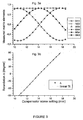
- Figure 3 shows the experimental values of the diagonal block elements of the Mueller matrix of a high quality Babinet-Soleil compensator as a function of the setting x (mm) of the micrometric screw controlling the compensator retardation Δ (Fig. 3a), together with a plot of the values of Δ (deduced from the measured matrix elements according to eqs.(2)) versus the setting x (mm) of the micrometric screw (squares) and the corresponding linear regression (solid line) (Fig. 3b).
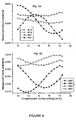
- Figure 4 shows the off diagonal block elements of the same Mueller matrix versus the setting x (mm) of the micrometric screw controlling the compensator retardation Δ.
- These drawings are provided for illustrative purposes only and should not be used to unduly limit the scope of the invention.
- Figure 1 shows a polarimetric system according to an embodiment of the invention. It contains an
excitation section 1 emitting alight beam 2 and ananalysis section 3. - The
excitation section 1 comprises a polarization state generator 4 (PSG) through which passes thelight beam 2. The polarization state generator 4 comprises apolarizer 5 that linearly polarizes thelight beam 2 along a polarization direction (i). - First
optical means 6 defines the geometry of thebeam 2 at thesample 7. - The
analysis section 3 comprises a polarization state detector 8 (PSD) containing ananalyzer 9 and detection means 10 for detecting thelight beam 2. - In a particular embodiment, the detection means 10 comprises a multipoint photosensitive detector that produces electrical signals sent to a
processing unit 11. Said detection means 10 are adapted to polarimetric imaging and the multipoint photosensitive detector is advantageously a charge coupled detector (CCD). - The polarimetric system may comprise as well a monochromator which is located in a first embodiment within the
light source 12 that emits thelight beam 2, before said beam enters the polarization state generator 4. In a second embodiment, the monochromator is located within the detection means 10, after the light beam exits thepolarization state detector 8. - According to the invention, the polarization state generator 4 of the polarimetric system comprises a first and a second
liquid crystal elements 13 having birefringent axes, saidliquid crystal elements 13 being positioned after thepolarizer 5. Thepolarization state detector 8 also comprises a first and a secondliquid crystal elements 14 having birefringent axes and positioned before theanalyzer 9. The polarimetric system comprises also control means for controlling saidliquid crystal elements - The present invention concerns Mueller polarimetric systems for analyzing samples represented by the sixteen coefficients of a Mueller matrix. The polarization state generator (PSG) 4 and the polarisation state detector (PSD) 8 comprise each a first and a second
liquid crystal elements - When NLCs are used, each NLCj element 13 of the PSG 4 (respectively, for each NLCj element 14 of the PSD 8), has an extraordinary axis making a fixed angle θj (resp. θ'j) with respect to the direction of polarisation (i) and a variable retardation δj (resp. δ'j) between its ordinary and extraordinary axes, which can be controlled electronically, said liquid crystal (NLCj)
elements 14 being positioned in reverse order in thePSD 8 with respect to the NLCj elements 13 of the PSG 4. - When FLCs are used, each FLCj element 13 of the PSG 4 (respectively, for each
FLC j 14 element of the PSD 8), has a constant retardation δj (resp. δ'j) between its ordinary and extraordinary axes, and the angle θj (resp. θ'j) between the extraordinary axis of the FLC and the direction of polarization (i) can be switched between two values separated by 45° by means of an electronic control device. Said liquid crystal (FLCj)elements 14 are positioned in reverse order in thePSD 8 with respect to the FLCj elements 13 of the PSG 4. - It is known that the application by control means of an appropriate voltage signal on each liquid crystal element (FLC or NLC) 13, 14 allows modulating the polarization of a light beam passing through said
liquid crystal elements - In mathematical terms, the liquid
crystal elements LC j 13 of the polarization state generator 4 applies a polarization modulation such that the Stokes vector (S) of thelight beam 2 at the exit of the polarization state generator 4 is given by:
- In a preferred embodiment, the liquid crystal (LC)
elements 13 according to the invention are nematic liquid crystal cells (NLC). Said liquid cells are particularly suitable to polarimetric imaging since their typical transmission range is currently between 400 nm and 1500 nm, and could be extended with new liquid crystal materials. - With NLCs, the orientation angles θ'j (j=1,2) are equal to θj (j=1,2) and the retardations δ'j (j=1,2) are equal to -δj (j=1,2) (modulo 2π). Advantageously then, the couple of retardations (δ1, δ2) takes sequentially the following values : (Δ1,Δ1), (Δ1,Δ2), (Δ2,Δ1), (Δ2,Δ2), where Δ1 and Δ2 verify the formulae (315° +
p 90°) and (135° +p 90°) respectively, where p is the same integer in both formulae and the angles θ1 and θ2 verify the formulae (ε 27° +q 90°) and (ε 72° +r 90°) respectively where ε = ± 1 has the same value in both equations while q and r are any integer, with tolerances on the angles θi and on the retardations Δi equal to +-10° and +-20° respectively. This embodiment allows the simultaneous optimization of the condition numbers s(W) and s(A), both A and W matrices being non singular. - The
LC elements - With FLCs, the extraordinary axes of the FLC make a couple of azimuthal angles (θ1,θ2) (resp. (θ'1,θ'2)) with respect to the direction of the
input polarizer 5 of the PSG 4 (resp. theoutput analyzer 9 of the PSD, and by means of a suitable electronic control device, these angles are set sequentially to (θ1,θ2), (θ1+45°,θ2), (θ1,θ2+45°), (θ1+45°,θ2+45°). The azimuthal angles θ'j are equal to θj (j=1,2) and the retardations δ'j are equal to -δj (j=1,2) (modulo 2π) for simultaneous optimization of the condition numbers s(W) and s(A) of the modulation and analysis matrices.
The retardations δi are given by δ1=80°+-15° and δ2=160°+-15°, while the orientation angles θi are given by θ1 = 67°+-10° and θ2 = 160°+-40°. - With FLCs and for spectroscopic applications (i.e. operation at variable wavelengths), as the values of the retardations (δ1, δ2) are not electrically controllable as for nematic liquid crystals, a birefringent plate is preferentially inserted between the two FLCs elements, leading to an overall optimization of A and W matrices in the whole transparency range of the FLCs, which is currently from 420 nm to 800 nm, and might be extended in the future with new materials. With typical values of FLC birefringence dispersion, the retardations (δ1, δ2) can be advantageously chosen equal to (90°, 180°) in the green part of the spectrum, while the birefringent plate can be chosen as a zero order quarter wave in the red part of the spectrum (633 nm), said plate being made of quartz. Hence, in a particular embodiment and for spectroscopic applications, the birefringent plate is a quartz plate and the PSG 4 comprises:
- ◆ a linear polarizer, set by definition at an orientation angle θ=0,
- ◆ a first ferroelectric liquid crystal, with a retardation δ1= 90°+-5° at 510 nm, set at an orientation angle θ1= -10°+-5°,
- ◆ a quartz plate, providing a (true zero order) retardation δQ=90°+-5° at 633 nm, set at an orientation angle θQ= 5°+-5°,
- ◆ a second ferroelectric liquid crystal, with a retardation δ2=180°+-15° at 510 nm, set at an orientation angle θ2= 71°+-10°.
- The invention regards as well conventional ellipsometry that is a special case of polarimetry for isotropic layers with smooth interfaces.
- Figure 2 shows a particular embodiment in which a spectroscopic ellipsometric system based on ferroelectric liquid crystals (FLCs) contains an
excitation section 1 emitting alight beam 2, asample holder 15 and ananalysis section 3. - The
excitation section 1 comprises a polarization state generator 4 (PSG) through which passes thelight beam 2. The polarization state generator 4 comprises apolarizer 5 that linearly polarizes thelight beam 2 along a polarization direction (i). Firstoptical means 6 focuses thebeam 2 at thesample 7. - The incidence angle of the
light beam 2 on the sample surface is defined as the angle at which the focused beam strikes the sample surface with respect to the normal to thesurface 7. For example, abeam 2 with normal incidence at the sample surface has an incidence angle of zero degree. The angle of incidence of the beam can be advantageously varied. The purpose of the focusing beam is to obtain a small spot on thesample 7, i.e. a compact spot with preferably dimensions inferior to a few tenths of mm2. This spot should provide a lateral resolution sufficient to map the sample surface. Thelight beam 2 emitted by theexcitation section 1 is in the transparency spectral region of the FLC, which is currently from 420 to 800 nm, and might be extended further with new FLC materials. - The
beam 2 reflects off the sample surface and passes through theanalysis section 3. In a more general case, the beam is scattered by the sample surface and passes through theanalysis section 3. Theanalysis section 3 comprises an input optical (collimating)system 16, a polarisation state detector 8 (PSD) containing ananalyzer 9 and detection means 10 for detecting thelight beam 2. The detection means 10 typically comprises a spectrometer coupled to several photodetectors, typically an array of CCD (charge coupled devices) that produces electrical signals. Aprocessing unit 11 receives said electrical signals. - According to the invention, the polarization state generator 4 of the polarimetric system comprises a first and a second ferroelectric
liquid crystal elements 13 having birefringent axes, saidliquid crystal elements 13 being positioned after thepolarizer 5, and a fixedretardation plate 17, between the twoliquid crystal elements 13. Thepolarization state detector 8 also comprises a first and a second ferroelectricliquid crystal elements 14 having birefringent axes and positioned before theanalyzer 9, and a fixedretardation plate 18 set between the FLCs. The polarimetric system comprises also control means for controlling saidliquid crystal elements - The present invention can also be advantageously implemented for polarimetric imaging by a CCD camera.
- The polarimetric system and the polarimetric measurement process according to the invention have been the object of various implementations whose following example demonstrates the quality of the results obtained.
- Figures 3 and 4 show the results obtained with a polarimetric system based on nematic liquid crystals, calibrated and operated in transmission, at 633 nm. The test sample was a high quality Babinet-Soleil compensator, which can be considered as dichroïc retarder (DR) with Ψ ≈ 45° and a retardation Δ which is a linear function of the setting of the compensator micrometric screw. The 16 elements of the compensator Mueller matrix (M) were measured for different settings of this screw.
- The experimental values for the diagonal block elements are shown on Fig. 3a, versus the screw settings (in mm) of the micrometric screw controlling the compensator retardation Δ; these values follow quite closely (to within 0.01) the behavior expected from eqs.(2) for Ψ=45°. In Fig. 3b is shown the variation of the dephasing Δ, as deduced from the values of the lower diagonal block elements, as a function of the screw setting: the standard deviation from a perfect linear fit is 0.13°, equivalent to λ/2700, which is even better than the accuracy specified by the manufacturer of the compensator, thus confirming the performance of this polarimetric technique.
Figure 4 shows the results obtained for the off-diagonal block elements of the Mueller matrix, again as a function of the micrometric screw setting (in mm). We recall that these elements are expected to vanish. Some of these elements, shown on Fig 4a, are independent of the compensator orientation, and they are always found to be smaller than 5.10-3 in absolute value. For the other ones (Fig 4b) this absolute value can reach 1.5 10-2. This latter value might be due in part to an imperfect alignment of the components within the compensator itself.
Claims (21)
- A polarimetric system for analyzing a sample comprising:- an excitation section (1) emitting a light beam, said excitation section (1) comprising a polarization state generator PSG (4) containing a polarizer (5) polarizing the incident light beam (2) linearly along a direction of polarization (i);- an analysis section (3) comprising a polarization state detector PSD (8) containing an analyzer (9) analysing a light beam linearly along a direction of analysis, and detection means (10);- a processing unit (11),
characterised in that said PSG comprises a first and a second liquid crystal elements LCj=1,2 (13), the second liquid crystal element LC2 being nearer the exit of the PSG than the first liquid crystal element LC1, and said PSD comprises a first and a second liquid crystal elements LC'j=1, 2 (14), the second liquid crystal element LC'2 being nearer the entry of the PSD than the first crystal element LC'1; each LCj=1,2 of the PSG, respectively each LC'j=1,2 of the PSD, having an extraordinary axis making an angle θj=1,2, respectively an angle θ'j=1,2, with respect to the direction of polarization of the polarizer, respectively to the direction of analysis of the analyser, and a retardation δj=1,2, respectively a retardation δ'j=1,2, between its ordinary and extraordinary axes; and, in that, for each j from 1 to 2, the angle θ'j is equal to θj and the retardation δ'j is equal to - δj modulo 2π. - A polarimetric system according to claim 1, wherein said liquid crystal elements (13, 14) are nematic (NLCs) liquid crystals and the polarimetric system comprises an electronic control unit enabling polarization modulation by varying the retardations δj and δ'j for NLCs.
- A polarimetric system according to claim 1, wherein said liquid crystal elements (13, 14) are ferroelectric (FLCs) liquid crystals, and the polarimetric system comprises an electronic control enabling polarization modulation by varying the orientation angles θj and θ'j for FLCs.
- A polarimetric system according to claims 1 and 2, wherein:- the couple of retardations (δ1, δ2) is varied in the following sequence (Δ1,Δ1), (Δ1,Δ2), (Δ2,Δ1), (Δ2,Δ2), where Δ1 and Δ2 verify the formulae Δ1 = 315° + p 90° and Δ2=135° + p 90° respectively, where p is the same integer in both formulae, with a tolerance of +/- 20°,- the orientations angles θ1 and θ2 verify the formulae θ1 = ε 27° + q 90° and θ2 = ε 72° + r 90° respectively where ε = ± 1 has the same value in both equations while q and r are any integer, with a tolerance of +/-10°.
- A polarimetric system according to claims 1 and 3, wherein:- the orientations of the extraordinary axes are set sequentially to (θ1,θ2), (θ1+45°,θ2), (θ1,θ2+45°), (θ1+45°,θ2+45°),- the retardations δ1, δ2 verify δ1=80°+/-15° and δ2=160°+/-15°, while the orientation angles θ1, θ2 are given by θ1 = 67°+/-10° and θ2 = 160°+/-40°.
- A polarimetric system according to claim 5, wherein the polarimetric system is suitable for a range of wavelengths, and a fixed retardation plate (17, 18) is placed between said two FLCs, both in the PSG and in the PSD.
- A polarimetric system according to claim 6, wherein said polarimetric system is optimized for the spectral range from 420 nm to 800 nm, and the retardation plate is a quartz plate and PSG comprises- a linear polarizer, set at an orientation angle θ=0,- a first ferroelectric liquid crystal, with a retardation δ1=90°+-5° at 510 nm, set at an orientation angle θ1=-10°+/-5°,- a quartz plate, providing a retardation δQ=90°+/-5° at 633 nm, set at an orientation angle θQ=5°+/-5°,- a second ferroelectric liquid crystal, with a retardation δ2=180°+/-15° at 510 nm, set at an orientation angle θ2=71°+/-10°.
- A polarimetric system according to claim 1 to 7, wherein said polarimetric system is an ellipsometer.
- A polarimetric system according to any one of the claims 1 to 7, wherein said polarimetric system is a Mueller polarimetric system for analyzing a sample (7) through the measurement of the sixteen coefficients of its Mueller matrix.
- A polarimetric system according to any one of claims 1 to 9, wherein the light beam (2) emitted by the excitation section (1) is in the spectral range 400-1500 nm for nematic liquid crystals, and 420-800 nm for ferroelectric liquid crystals.
- A polarimetric system according to any one of claims 1 to 10, wherein the excitation section (1) comprises a monochromator positioned before the polarization state generator PSG (4).
- A polarimetric system according to any one of claims 1 to 10, wherein the detection means (10) comprises a monochromator, placed after the PSD.
- A polarimetric system according to any one of claims 1 to 12, wherein the detection means (10) comprises a multipoint photosensitive detector, adapted with the processing unit (11) to polarimetric imaging.
- A polarimetric system according to claim 13, wherein the multipoint photosensitive detector is a charge coupled detector (CCD).
- A calibration process of a polarimetric system according to claim 1 adapted to the complete Mueller polarimetry in transmission of a sample, characterized in that said polarimetric system comprises:- a polarisation state generator PSG modulating an incident light beam (2) polarization, containing a polarizer, a first and a second liquid crystal elements LCj=1, 2 (13) positioned after the polarizer, the second liquid crystal element LC2 being nearer the exit of the PSG than the first crystal element LC1, each of said LCj element having a retardation δj=1, 2 between its ordinary and extraordinary axis and said extraordinary axis making an angle θj=1,2 with respect to the polarization direction (i) defined by the linear polarizer, so that, by varying the retardation δj of each LCj element for a fixed value of the angle θj, when the LCj elements are nematic LCs, or by switching the orientation angle θj for fixed δj when the LCj elements are ferroelectric LCs, one modulates the incident light beam (2) polarization, the PSG having a modulation matrix W that is non singular;- a polarization state detector PSD (8) containing an analyzer (9), detection means (10), and a first and a second liquid crystal elements LC'j=1,2 (14) positioned before the analyser, the second liquid crystal element LC'2 being nearer the entry of the PSD than the first crystal element LC'1, each of said LC'j elements (14) having a retardation δ'j=1, 2 between its ordinary and extraordinary axis and said extraordinary axis making an angle θ'j=1,2 with respect to the direction of analysis of the analyser, said LC'j elements (14) being the same as the LCj elements (13) of the PSG, so that by varying the retardation δ'j of each LC'j element for fixed values of angles θ'j when the LC'j are nematic LCs, or by switching the values of angles θ'j for fixed δ'j when the LC'j are ferroelectric LCs, one generates a detection matrix A that is non singular;and characterised in that said process comprises the step of:- choosing a set of reference sample elements (p) comprising dichroïc retarders with approximately known Mueller matrices M p, defined by the parameters τp,Ψp and Δp, one of these reference sample elements being the identity matrix I o describing propagation in air; and,for each of the reference sample elements (p) taking a complete measurement of said reference sample element set at an orientation angle θp by:- illuminating said reference sample element with said polarized incident light beam (2) emitted by said PSG;- detecting a measurement beam transmitted by said reference sample element with an analysis section (3) comprising said PSD and detection means (10), so that for a given set of retardations δj, δ'j or for a given set of orientation angles θj, θ'j, one produces a measured quantity Dn;- processing the electrical signals produced by the detection means (10) in accordance with the measured quantity with a processing unit (11) to construct the matrix AR(-θp)M p R(θp)W, this matrix being a product of the detection matrix A, the Mueller matrix R(-θp)M p R(θp) of said reference sample element (p) set at the angle θp, with R(θ) a matrix describing a rotation by an angle θ about the z axis and the modulation matrix W,- calculating the product (Al o W)-1(AR(-θp)M p R(θp)W) for each reference sample element (p) in order to obtain an experimental matrix (Cp),- determining the actual values of τp,Ψp and Δp, and thus the matrix M p, independently of the angles θp, from the eigenvalues of C p,- constructing a matrix (K tot(θp)) equal to
 - determining the eigenvalues λi=1, 16 of the K tot(θp) matrix in order to extract the modulation matrix W that verifies K tot (W)=0, the p reference sample element being chosen so that one and only one eigenvalue λi vanishes when the angles θp used in the calculation of K tot(θp) are set equal to their actual values during the calibration measurements, while the other eigenvalues λj, being sorted in decreasing order of value, verify Z=λ15/λ1 < 1 and the ratio Z is maximised,- determining the angles θp by requiring one of the eigenvalues K tot(θp) to vanish, W being the associated eigenvector,- determining the detection matrix A by constructing the product (Al o W) (W -1).
 - A calibration process according to claim 15, wherein a set of reference sample elements comprises:- a linear polarizer set at θ1=0° orientation,- a linear polarizer set at θ2 = 90° +/- 5° orientation,- a retardation plate with a retardation δ=110°+/-30° set at θ3=30°+/-5°.
- A calibration process according to claim 16, wherein the retardation plate is an achromatic quarterwave plate.
- A calibration process of a polarimetric system according to claim 1 adapted to the complete Mueller polarimetry in reflection of a sample, characterised in that said polarimetric system comprises:- a polarisation state generator PSG modulating an incident light beam (2) polarization, containing a polarizer, a first and a second liquid crystal elements LCj=1, 2 (13) positioned after the polarizer, the second liquid crystal element LC2 being nearer the exit of the PSG than the first crystal element LC1, each of said LCj element having a retardation δj=1,2 between its ordinary and extraordinary axis and said extraordinary axis making an angle θj=1,2 with respect to the polarization direction (i) defined by the linear polarizer, so that, by varying the retardation δj of each LCj element for a fixed value of the angle θj, when the LCj elements are nematic LCs, or by switching the orientation angle θj for fixed δ2 when the LCj elements are ferroelectric LCs, one modulates the incident light beam (2) polarization, the PSG having a modulation matrix W that is non singular;- a polarization state detector PSD (8) containing an analyzer (9), detection means (10), and a first and a second liquid crystal elements LC'j=1,2 (14) positioned before the analyser, the second liquid crystal element LC'2 being nearer the entry of the PSD than the first crystal element LC'1, each of said LC'j elements (14) having a retardation δ'j=1, 2 between its ordinary and extraordinary axis and said extraordinary axis making an angle θ'j=1,2 with respect to the direction of analysis of the analyser, said LC'j elements (14) being the same as the LCj elements (13) of the PSG, so that by varying the retardation δ'j of each LC'j element for fixed values of angles θ'j when the LC'j are nematic LCs, or by switching the values of angles θ'j for fixed δ'j when the LC'j are ferroelectric LCs, one generates a detection matrix A that is non singular;and characterized in that said process comprises the step of:- choosing a set of reference sample elements comprising a linear polarizer, defined by its Mueller matrix M pol, and a first DR1 and a second DR2 dichroïc retarders, said DRi=1,2 having Mueller matrices M i=1,2 respectively, with approximately known values of the parameters τi=1,2, Ψi=1,2 and Δi=1,2;and, for each of the reference sample elements:- illuminating the reference sample element with the polarized incident light beam (2) emitted by said PSG;- detecting a measurement beam reflected by said reference sample element with an analysis section (3) comprising said PSD (8) and detection means (10); so that for a given set of retardations δj, δ'j or for a given set of orientation angles θj, θ'j, one produces a measured quantity D n; and- processing the electrical signals produced by the detection means (10) in accordance with the measured quantity with a processing unit (11), to produce a raw data matrix B = AMW, where M is the Mueller matrix of the reference sample element, in particular, the origin of the azimuthal angles (θ=0) being taken in the plane of incidence :◆ DR1 alone, set at θ=0, yielding a measured matrix B 1=AM 1 W◆ DR2 alone, set at θ=0, yielding a measured matrix B 2=AM 2 W◆ DR1, set at θ=0, and preceded by the polarizer (5) set at an orientation angle θ1, yielding a measured matrix B p1=AM 1 R(-θ1)M pol R(θ1)W, where R(θ) is a matrix describing a rotation by an angle θ about the z axis◆ DR1, set at θ=0, and followed by the polarizer, set at an orientation angle θ2, yielding the measured matrix B p2=AR(-θ2)M pol R(θ2)M 1 W;- Calculating the products C 1=B 2 -1 B 1 and C 2=B 1 B 2 -1 and then the matrices N 1=M 2 -1 M 1 and N 2=M 1 M 2 -1 through their eigenvalues, which are the same as those of C 1 and C 2;- Calculating the products C p1=B 2 -1 B p1=W -1 N 1 R(-θ1)M pol R(θ1)W and C p2=B p2 B 2 -1=AR(-θ2)M pol R(θ2)N 2 A -1:- Defining a K 1 matrix as K 1(θ1)[X]= H 1 T H 1+ H p1(θ1)T H p1(θ1), where, for any 4x4 real matrix X, H 1[X] and H p1(θ1)[X] are defined as
 - Determining the modulation matrix W and the orientation θ1 by requiring that K 1(θ1) has one vanishing eigenvalue, and W is the eigenvector associated with this vanishing eigenvalue;- Determining similarly the analysis matrix A as the eigenvector associated with the unique vanishing eigenvalue of the matrix
 o the 16x16 real symmetrical matrices K 1(θ1) and K 2(θ2) will only have one vanishing eigenvalue, if and only if the angles θ1 and θ2 used for their evaluation are equal to the azimuthal angles of the polarizers during the calibration measurements,o The next eigenvalues are as large as possible, or, more precisely, the ratios Z=λ15/λ1 of the smallest nonvanishing eigenvalues (λ15) over the largest (λ1) eigenvalues of K 1 and K 2 are as large as possible.
 - A calibration process according to claim 18, wherein the set of reference sample elements comprises:- a linear polarizer set at θ1=45°+/-5°- a linear polarizer set at θ2=-45°+/-5°, and- a couple of reference sample elements equivalent to a first DR1 and a second DR2 dichroïc retarders, both oriented at θ=0 with respect to the incidence plane, with Mueller matrices M 1 and M 2 such that the products M 2 -1 M 1 and M 2 -1 M 1 are the Mueller matrices of a DR with Ψ=45°+/-30° and Δ=90°+/-10.
- A calibration process according to claim 19, wherein for spectroscopic applications, said reference sample elements comprise a metallic mirror.
- A calibration process according to claim 20, wherein for spectroscopic applications said reference sample elements comprise an achromatic quarter-wave plate, oriented with one axis in the incidence plane placed before or after a metallic mirror.
Priority Applications (4)
| Application Number | Priority Date | Filing Date | Title |
|---|---|---|---|
| DE60209672T DE60209672T2 (en) | 2002-10-15 | 2002-10-15 | Liquid crystal based polarimetric system, method for its calibration, and polarimetric measurement method |
| EP02292544A EP1411333B1 (en) | 2002-10-15 | 2002-10-15 | A liquid crystal based polarimetric system, a process for its calibration, and a polarimetric measurement process |
| JP2003354750A JP4514430B2 (en) | 2002-10-15 | 2003-10-15 | Liquid crystal polarization analyzer |
| US10/684,361 US7196792B2 (en) | 2002-10-15 | 2003-10-15 | Liquid crystal based polarimetric system, a process for the calibration of this polarimetric system, and a polarimetric measurement process |
Applications Claiming Priority (1)
| Application Number | Priority Date | Filing Date | Title |
|---|---|---|---|
| EP02292544A EP1411333B1 (en) | 2002-10-15 | 2002-10-15 | A liquid crystal based polarimetric system, a process for its calibration, and a polarimetric measurement process |
Publications (2)
| Publication Number | Publication Date |
|---|---|
| EP1411333A1 EP1411333A1 (en) | 2004-04-21 |
| EP1411333B1 true EP1411333B1 (en) | 2006-03-08 |
Family
ID=32039232
Family Applications (1)
| Application Number | Title | Priority Date | Filing Date |
|---|---|---|---|
| EP02292544A Expired - Lifetime EP1411333B1 (en) | 2002-10-15 | 2002-10-15 | A liquid crystal based polarimetric system, a process for its calibration, and a polarimetric measurement process |
Country Status (4)
| Country | Link |
|---|---|
| US (1) | US7196792B2 (en) |
| EP (1) | EP1411333B1 (en) |
| JP (1) | JP4514430B2 (en) |
| DE (1) | DE60209672T2 (en) |
Families Citing this family (30)
| Publication number | Priority date | Publication date | Assignee | Title |
|---|---|---|---|---|
| US7116419B1 (en) * | 2002-11-15 | 2006-10-03 | Purdue Research Foundation | Wavelength-parallel polarization measurement systems and methods |
| US6970241B1 (en) * | 2004-08-24 | 2005-11-29 | Desa Richard J | Device for enabling slow and direct measurement of fluorescence polarization |
| FR2880129B1 (en) * | 2004-12-24 | 2007-04-20 | Ecole Polytechnique Etablissem | METROLOGICAL CHARACTERIZATION OF MICROELECTRONIC CIRCUITS |
| JP3909363B2 (en) | 2005-03-28 | 2007-04-25 | オムロン株式会社 | Spectral polarization measurement method |
| WO2006134840A1 (en) * | 2005-06-13 | 2006-12-21 | National University Corporation Tokyo University Of Agriculture And Technology | Optical characteristic measuring device and optical characteristic measuring method |
| ATE385736T1 (en) | 2005-07-01 | 2008-03-15 | Ecole Polytech | POLARIMETRIC ELECTRONIC IMAGING SYSTEM FOR A COLPOSCOPIC APPARATUS |
| US7796257B2 (en) * | 2006-01-13 | 2010-09-14 | National University Corporation Tokyo University Of Agriculture And Technology | Measuring apparatus, measuring method, and characteristic measurement unit |
| EP1811287A1 (en) * | 2006-01-20 | 2007-07-25 | Ecole Polytechnique | Polarimetric raman system and method for analysing a sample |
| EP1947445B1 (en) * | 2007-01-19 | 2010-07-14 | Horiba Jobin Yvon S.A.S. | System and process for analysing a sample |
| FR2937732B1 (en) * | 2008-10-29 | 2010-12-31 | Horiba Jobin Yvon Sas | DEVICE AND METHOD FOR SPECTROSCOPIC POLARIMETRIC MEASUREMENTS IN THE VISIBLE AND NEAR INFRARED DOMAIN |
| JP2010145332A (en) * | 2008-12-22 | 2010-07-01 | Tokyo Univ Of Agriculture & Technology | Optical characteristic measuring instrument, optical characteristic measurement method, and calibration method of optical characteristic measuring instrument |
| WO2012096520A2 (en) | 2011-01-11 | 2012-07-19 | Samsung Electronics Co., Ltd. | Uplink transmission power configuration method and apparatus for mobile communication system |
| WO2013013049A1 (en) * | 2011-07-19 | 2013-01-24 | The General Hospital Corporation | Systems, methods, apparatus and computer-accessible-medium for providing polarization-mode dispersion compensation in optical coherence tomography |
| CN103869830B (en) * | 2012-12-18 | 2016-11-23 | 睿励科学仪器(上海)有限公司 | A kind of control method using real time system control ellipsometer and real-time system |
| FR3008497B1 (en) * | 2013-07-10 | 2015-08-07 | Univ Strasbourg | DEVICE FOR COMPENSATING THE DERIVATIVE OF A PHASING MODULATOR OF A POLARIZATION STATE OF A LIGHT BEAM |
| WO2015125997A1 (en) * | 2014-02-20 | 2015-08-27 | 코스맥스 주식회사 | Method for detecting multi-layered structure of liquid crystal emulsion by measuring mueller matrix |
| FR3018914B1 (en) | 2014-03-18 | 2016-05-06 | Centre Nat Rech Scient | DEVICE AND METHOD FOR POLARIMETRIC CHARACTERIZATION DEPORTEE |
| CN104914497B (en) * | 2015-06-25 | 2017-03-29 | 武汉颐光科技有限公司 | A kind of composite wave plate phase delay device Optimization Design |
| US10564504B2 (en) * | 2017-11-30 | 2020-02-18 | Palo Alto Research Center Incorporated | Liquid-crystal variable retarder using liquid crystal cells of differing thicknesses |
| US10983338B2 (en) | 2017-12-29 | 2021-04-20 | Palo Alto Research Center Incorporated | Exit-pupil expander used distribute light over a liquid-crystal variable retarder |
| US10663346B2 (en) | 2017-12-29 | 2020-05-26 | Palo Alto Research Center Incorporated | Method and apparatus for transforming uniformly or non-uniformly sampled interferograms to produce spectral data |
| CN110261317B (en) * | 2019-06-17 | 2021-11-16 | 西安理工大学 | Measurement system and method for Mueller matrix spectrum |
| JP7440845B2 (en) * | 2019-06-18 | 2024-02-29 | 国立大学法人長岡技術科学大学 | polarization imaging device |
| CN110596012B (en) * | 2019-09-17 | 2021-01-15 | 华中科技大学 | Magneto-optical modulation ellipsometer device and measurement method |
| CN112525493B (en) * | 2020-11-13 | 2022-06-17 | 华中科技大学 | Method and device for detecting optical characteristics of ferroelectric liquid crystal delayer |
| CN113203686B (en) * | 2021-04-16 | 2023-02-14 | 中国科学院上海光学精密机械研究所 | A polarization characteristic detection device and detection method of a non-planar transparent element |
| WO2022251159A1 (en) * | 2021-05-24 | 2022-12-01 | Arizona Board Of Regents On Behalf Of The University Of Arizona | Devices and methods for determining polarization characteristics from partial polarimetry |
| CN115200712B (en) * | 2022-06-24 | 2025-04-29 | 中国科学院合肥物质科学研究院 | Mueller matrix measurement system and measurement method |
| CN116930093B (en) * | 2023-04-01 | 2024-01-26 | 中国人民解放军国防科技大学 | An error calibration method for double vortex wave plate Mueller matrix ellipsometer |
| CN119804335B (en) * | 2025-03-17 | 2025-07-01 | 浙江大学 | Snapshot Mueller matrix polarization imaging device and method based on photo-alignment liquid crystal chip |
Family Cites Families (10)
| Publication number | Priority date | Publication date | Assignee | Title |
|---|---|---|---|---|
| US4523848A (en) * | 1981-10-01 | 1985-06-18 | National Research Development Corporation | Polariscope |
| US5521705A (en) * | 1994-05-12 | 1996-05-28 | Oldenbourg; Rudolf | Polarized light microscopy |
| JPH08247853A (en) * | 1995-03-08 | 1996-09-27 | Shimadzu Corp | Liquid crystal light modulator |
| JPH10501072A (en) * | 1995-03-20 | 1998-01-27 | カンサス ステイト ユニバーシティ リサーチ フアウンデーション | Ellipsometry microscope |
| US5788632A (en) * | 1996-03-19 | 1998-08-04 | Abbott Laboratories | Apparatus and process for the non-invasive measurement of optically active compounds |
| JPH09204235A (en) * | 1996-05-30 | 1997-08-05 | Hamamatsu Photonics Kk | Optical correlator |
| FR2755254B1 (en) * | 1996-10-25 | 1999-01-15 | Centre Nat Rech Scient | OPTICAL MODULATION COMPONENT, POLARIMETER AND ELLIPSOMETER FROM MUELLER INCLUDING SUCH AN OPTICAL COMPONENT, METHOD FOR CALIBRATION OF THIS ELLIPSOMETER AND METHOD FOR ELLIPSOMETRIC MEASUREMENT |
| JP3425923B2 (en) * | 2000-03-27 | 2003-07-14 | Necエレクトロニクス株式会社 | Evaluation method and evaluation device for anisotropic multilayer thin film structure |
| JP3537732B2 (en) * | 2000-04-18 | 2004-06-14 | 独立行政法人 科学技術振興機構 | Ellipsometer using voltage controlled liquid crystal retarder |
| US6373614B1 (en) * | 2000-08-31 | 2002-04-16 | Cambridge Research Instrumentation Inc. | High performance polarization controller and polarization sensor |
-
2002
- 2002-10-15 EP EP02292544A patent/EP1411333B1/en not_active Expired - Lifetime
- 2002-10-15 DE DE60209672T patent/DE60209672T2/en not_active Expired - Lifetime
-
2003
- 2003-10-15 JP JP2003354750A patent/JP4514430B2/en not_active Expired - Lifetime
- 2003-10-15 US US10/684,361 patent/US7196792B2/en not_active Expired - Lifetime
Also Published As
| Publication number | Publication date |
|---|---|
| EP1411333A1 (en) | 2004-04-21 |
| US7196792B2 (en) | 2007-03-27 |
| JP4514430B2 (en) | 2010-07-28 |
| DE60209672D1 (en) | 2006-05-04 |
| US20040130717A1 (en) | 2004-07-08 |
| DE60209672T2 (en) | 2006-11-16 |
| JP2004271510A (en) | 2004-09-30 |
Similar Documents
| Publication | Publication Date | Title |
|---|---|---|
| US7196792B2 (en) | Liquid crystal based polarimetric system, a process for the calibration of this polarimetric system, and a polarimetric measurement process | |
| EP0914600B1 (en) | Broadband spectroscopic rotating compensator ellipsometer | |
| US6052188A (en) | Spectroscopic ellipsometer | |
| US10634607B1 (en) | Snapshot ellipsometer | |
| EP1947445B1 (en) | System and process for analysing a sample | |
| US7248362B2 (en) | Small-spot spectrometry instrument with reduced polarization and multiple-element depolarizer therefor | |
| US6222627B1 (en) | Wollaston prism and use of it in a fourier-transform spectrometer | |
| US20070146706A1 (en) | Broadband ellipsometer / polarimeter system | |
| EP1811287A1 (en) | Polarimetric raman system and method for analysing a sample | |
| US8564777B1 (en) | System and method for compensating detector non-idealities | |
| US6781692B1 (en) | Method of monitoring the fabrication of thin film layers forming a DWDM filter | |
| US11391666B1 (en) | Snapshot ellipsometer | |
| KR100870132B1 (en) | Spectroscopic Ellipsometer Using Acousto-optic Modulation Filter and Its Elliptic Analysis Method | |
| EP1038165B1 (en) | Regression calibrated spectroscopic rotating compensator ellipsometer system with photo array detector | |
| Sassella et al. | Generalized anisotropic ellipsometry applied to an organic single crystal: Potassium acid phthalate | |
| Garcia-Caurel et al. | Focal Point Review-Application of Spectroscopic Ellipsometry and Mueller Ellipsometry to Optical Characterization |
Legal Events
| Date | Code | Title | Description |
|---|---|---|---|
| PUAI | Public reference made under article 153(3) epc to a published international application that has entered the european phase |
Free format text: ORIGINAL CODE: 0009012 |
|
| AK | Designated contracting states |
Kind code of ref document: A1 Designated state(s): AT BE BG CH CY CZ DE DK EE ES FI FR GB GR IE IT LI LU MC NL PT SE SK TR |
|
| AX | Request for extension of the european patent |
Extension state: AL LT LV MK RO SI |
|
| 17P | Request for examination filed |
Effective date: 20040407 |
|
| 17Q | First examination report despatched |
Effective date: 20040727 |
|
| AKX | Designation fees paid |
Designated state(s): CH DE FR GB IT LI |
|
| GRAP | Despatch of communication of intention to grant a patent |
Free format text: ORIGINAL CODE: EPIDOSNIGR1 |
|
| RIN1 | Information on inventor provided before grant (corrected) |
Inventor name: DE MARTINO, ANTONELLO Inventor name: DREVILLON, BERNARD |
|
| GRAS | Grant fee paid |
Free format text: ORIGINAL CODE: EPIDOSNIGR3 |
|
| GRAA | (expected) grant |
Free format text: ORIGINAL CODE: 0009210 |
|
| AK | Designated contracting states |
Kind code of ref document: B1 Designated state(s): CH DE FR GB IT LI |
|
| PG25 | Lapsed in a contracting state [announced via postgrant information from national office to epo] |
Ref country code: IT Free format text: LAPSE BECAUSE OF FAILURE TO SUBMIT A TRANSLATION OF THE DESCRIPTION OR TO PAY THE FEE WITHIN THE PRESCRIBED TIME-LIMIT;WARNING: LAPSES OF ITALIAN PATENTS WITH EFFECTIVE DATE BEFORE 2007 MAY HAVE OCCURRED AT ANY TIME BEFORE 2007. THE CORRECT EFFECTIVE DATE MAY BE DIFFERENT FROM THE ONE RECORDED. Effective date: 20060308 |
|
| REG | Reference to a national code |
Ref country code: GB Ref legal event code: FG4D |
|
| REG | Reference to a national code |
Ref country code: CH Ref legal event code: EP |
|
| REF | Corresponds to: |
Ref document number: 60209672 Country of ref document: DE Date of ref document: 20060504 Kind code of ref document: P |
|
| REG | Reference to a national code |
Ref country code: CH Ref legal event code: NV Representative=s name: KIRKER & CIE SA |
|
| ET | Fr: translation filed | ||
| PLBE | No opposition filed within time limit |
Free format text: ORIGINAL CODE: 0009261 |
|
| STAA | Information on the status of an ep patent application or granted ep patent |
Free format text: STATUS: NO OPPOSITION FILED WITHIN TIME LIMIT |
|
| 26N | No opposition filed |
Effective date: 20061211 |
|
| PGFP | Annual fee paid to national office [announced via postgrant information from national office to epo] |
Ref country code: CH Payment date: 20140925 Year of fee payment: 13 |
|
| PGFP | Annual fee paid to national office [announced via postgrant information from national office to epo] |
Ref country code: IT Payment date: 20140929 Year of fee payment: 13 |
|
| REG | Reference to a national code |
Ref country code: FR Ref legal event code: PLFP Year of fee payment: 14 |
|
| REG | Reference to a national code |
Ref country code: CH Ref legal event code: PL |
|
| PG25 | Lapsed in a contracting state [announced via postgrant information from national office to epo] |
Ref country code: LI Free format text: LAPSE BECAUSE OF NON-PAYMENT OF DUE FEES Effective date: 20151031 Ref country code: IT Free format text: LAPSE BECAUSE OF NON-PAYMENT OF DUE FEES Effective date: 20151015 Ref country code: CH Free format text: LAPSE BECAUSE OF NON-PAYMENT OF DUE FEES Effective date: 20151031 |
|
| REG | Reference to a national code |
Ref country code: FR Ref legal event code: PLFP Year of fee payment: 15 |
|
| REG | Reference to a national code |
Ref country code: FR Ref legal event code: PLFP Year of fee payment: 16 |
|
| REG | Reference to a national code |
Ref country code: FR Ref legal event code: PLFP Year of fee payment: 17 |
|
| PGFP | Annual fee paid to national office [announced via postgrant information from national office to epo] |
Ref country code: GB Payment date: 20211020 Year of fee payment: 20 Ref country code: DE Payment date: 20211008 Year of fee payment: 20 |
|
| PGFP | Annual fee paid to national office [announced via postgrant information from national office to epo] |
Ref country code: FR Payment date: 20211029 Year of fee payment: 20 |
|
| REG | Reference to a national code |
Ref country code: DE Ref legal event code: R071 Ref document number: 60209672 Country of ref document: DE |
|
| REG | Reference to a national code |
Ref country code: GB Ref legal event code: PE20 Expiry date: 20221014 |
|
| PG25 | Lapsed in a contracting state [announced via postgrant information from national office to epo] |
Ref country code: GB Free format text: LAPSE BECAUSE OF EXPIRATION OF PROTECTION Effective date: 20221014 |