EP1411327A1 - Thermal air flow rate measuring apparatus and its flowmeter and internal combustion engine and thermal air flow rate measuring method using it - Google Patents
Thermal air flow rate measuring apparatus and its flowmeter and internal combustion engine and thermal air flow rate measuring method using it Download PDFInfo
- Publication number
- EP1411327A1 EP1411327A1 EP01954362A EP01954362A EP1411327A1 EP 1411327 A1 EP1411327 A1 EP 1411327A1 EP 01954362 A EP01954362 A EP 01954362A EP 01954362 A EP01954362 A EP 01954362A EP 1411327 A1 EP1411327 A1 EP 1411327A1
- Authority
- EP
- European Patent Office
- Prior art keywords
- flow rate
- air flow
- heating resistor
- fluid
- output
- Prior art date
- Legal status (The legal status is an assumption and is not a legal conclusion. Google has not performed a legal analysis and makes no representation as to the accuracy of the status listed.)
- Withdrawn
Links
Images






Classifications
-
- G—PHYSICS
- G01—MEASURING; TESTING
- G01F—MEASURING VOLUME, VOLUME FLOW, MASS FLOW OR LIQUID LEVEL; METERING BY VOLUME
- G01F1/00—Measuring the volume flow or mass flow of fluid or fluent solid material wherein the fluid passes through a meter in a continuous flow
- G01F1/68—Measuring the volume flow or mass flow of fluid or fluent solid material wherein the fluid passes through a meter in a continuous flow by using thermal effects
- G01F1/684—Structural arrangements; Mounting of elements, e.g. in relation to fluid flow
- G01F1/6845—Micromachined devices
-
- G—PHYSICS
- G01—MEASURING; TESTING
- G01F—MEASURING VOLUME, VOLUME FLOW, MASS FLOW OR LIQUID LEVEL; METERING BY VOLUME
- G01F1/00—Measuring the volume flow or mass flow of fluid or fluent solid material wherein the fluid passes through a meter in a continuous flow
- G01F1/68—Measuring the volume flow or mass flow of fluid or fluent solid material wherein the fluid passes through a meter in a continuous flow by using thermal effects
- G01F1/696—Circuits therefor, e.g. constant-current flow meters
- G01F1/6965—Circuits therefor, e.g. constant-current flow meters comprising means to store calibration data for flow signal calculation or correction
-
- G—PHYSICS
- G01—MEASURING; TESTING
- G01F—MEASURING VOLUME, VOLUME FLOW, MASS FLOW OR LIQUID LEVEL; METERING BY VOLUME
- G01F1/00—Measuring the volume flow or mass flow of fluid or fluent solid material wherein the fluid passes through a meter in a continuous flow
- G01F1/68—Measuring the volume flow or mass flow of fluid or fluent solid material wherein the fluid passes through a meter in a continuous flow by using thermal effects
- G01F1/696—Circuits therefor, e.g. constant-current flow meters
- G01F1/698—Feedback or rebalancing circuits, e.g. self heated constant temperature flowmeters
-
- G—PHYSICS
- G01—MEASURING; TESTING
- G01F—MEASURING VOLUME, VOLUME FLOW, MASS FLOW OR LIQUID LEVEL; METERING BY VOLUME
- G01F1/00—Measuring the volume flow or mass flow of fluid or fluent solid material wherein the fluid passes through a meter in a continuous flow
- G01F1/68—Measuring the volume flow or mass flow of fluid or fluent solid material wherein the fluid passes through a meter in a continuous flow by using thermal effects
- G01F1/696—Circuits therefor, e.g. constant-current flow meters
- G01F1/698—Feedback or rebalancing circuits, e.g. self heated constant temperature flowmeters
- G01F1/6983—Feedback or rebalancing circuits, e.g. self heated constant temperature flowmeters adapted for burning-off deposits
-
- G—PHYSICS
- G01—MEASURING; TESTING
- G01F—MEASURING VOLUME, VOLUME FLOW, MASS FLOW OR LIQUID LEVEL; METERING BY VOLUME
- G01F1/00—Measuring the volume flow or mass flow of fluid or fluent solid material wherein the fluid passes through a meter in a continuous flow
- G01F1/72—Devices for measuring pulsing fluid flows
Definitions
- the present invention relates to a novel thermal air flow rate measuring apparatus and a novel thermal air flow rate measuring method, and to an internal combustion engine using the thermal air flow rate measuring apparatus and a thermal air flow rate measuring method suitable for detecting an intake air flow rate of the internal combustion engine.
- air flow rate measuring apparatuses of thermal type have been widely used because of capability of directly detecting a mass air flow rate.
- its heating resistor is constructed by winding a platinum wire around a bobbin and then coating the wire with glass, or by forming a thin film resistor on a ceramic substrate or a silicon substrate.
- a heating resistor is heated up to a given temperature and a flow rate is directly detected from a value of current flowing through the resisto r when a fluid flows
- a type in which temperature detecting resistors are arranged in both sides of a heating resistor and a flow rate is detected from a temperature difference between the temperature detecting resistors there are a type in which a heating resistor is heated up to a given temperature and a flow rate is directly detected from a value of current flowing through the resisto r when a fluid flows.
- the conventional air fl ow rate measuring apparatus requires an output signal corresponding to the air flow direction because the accuracy of the measured flow rate becomes poor.
- the type in which temperature detecting resistors are arranged in both sides of the heating resistor and an air flow rate is detected from a temperature difference between the temperature detecting resistors, is suitable for detecting an output signal under the condition of existing of the reversed air flow because the output signal corresponds to the flow direction.
- An object of the present invention is to provide a thermal air flow rate measuring apparatus and a thermal air flow mater having high accuracy, in which sensitivity is enhanced by an operating means using sensors having different output characteristics and employing a digitized signal, and the sensitivity and temperature can be corrected easily depending on the flow direction of fluid, and to provide an internal combustion engine and a thermal air flow rate measuring method using the th ermal air flow rate measuring apparatus.
- the present invention is characterized by a thermal air flow rate measuring apparatus comprising at least one heating resistor disposed in a gas fluid, temperature detecting resistors formed at an upstream part and a downstream part of the heating resistor in a flow direction of the fluid, an output means for outputting at least two signals relating to a flow rate of said fluid from the heating resistor and the temperature detecting resistors, a quantizing means (a digitizing means) for quantizing (digital-converting) the output values, and an operating means for operating the flow rate based on the quantized signals; or a thermal air flow raxe measuring apparatus comprising an operating means for operating the at le ast two quantized (digital-converted) signals using at least two parameters, and a synthesizing and outputting means for synthesizing the operated signals and outputting the synthesized result; or a thermal air flow rate measuring apparatus comprising an o perating means for operating the at least two quantized (digital-converted) signals using at least two parameters, and an output means for synthesizing the
- the present invention is characteri zed by a thermal air flow rate measuring apparatus comprising at least one heating resistor disposed in a gas fluid, a flow rate detecting means for detecting a flow rate of the fluid using the heating resistor by driving the heating resistor at a constant temperature using a temperature compensating resistor; flow rate detecting means for detecting the flow rate from a temperature difference between temperature detecting resistors each arranged in both sides of the heating resistor; a quantizing means (a digitizing means) for quantizing (digitizing) a value from the heating resistor and a value according to the temperature difference; an operating means for operating the quantized (digital-converted) values; and a correcting means for correcting the operate d values.
- a thermal air flow rate measuring apparatus comprising at least one heating resistor disposed in a gas fluid, a flow rate detecting means for detecting a flow rate of the fluid using the heating resistor by driving the heating resistor at a constant temperature using a temperature compensating resistor; flow rate detecting means for
- the present invention is characterized by a thermal air flow rate measuring apparatus comprising at least one heating resistor disposed in a gas fluid; temperature detecting resistors formed at an upper stream part and a downstream part of the heating resistor in a flow direction of the fluid, the temperature detecting resistors being arranged in multi-stage along a longitudinal direction of the heating resistor individually at the upstream part and the downstream part; in addition, an o utput means for outputting at least two signals relating to a flow rate of the fluid from the heating resistor and the temperature detecting resistors; a quantizing means for quantizing the output values; and an operating means for operating the flow rater and directions of the fluid based on the quantized signals.
- the present invention is characterized by a thermal air flow rate measuring method, which operates a flow rate and a flow direction of a gas fluid based on a signal relating to an amount of heat generated by at least one heating resistor disposed in the gas fluid; a signal relating to a temperature difference between an upstream part and a downstream part of temperature detecting resistors in a flow direction of the fluid, said temperature detect ing resistors being formed in multistage respectively at the upstream part and the downstream part of the heating resistor; and a signal relating to a flow difference of the fluid other than the temperature difference, or, in addition to these, based on quantized signals obtained by quantizing the signals described above.
- the present invention comprises a heating resistor; a means for detecting a flow rate by driving the heating resistor at a constant temperature using a temperature compensation resistor; a means for detecting a flow rate from a temperature difference between temperature detecting resistors by arranging the temperature detecting resistors in both sides of the heating resistor; a quantizing means (a digitizing means) for inpu tting a signal corresponding to the flow rate obtained from the heating resistor and a signal corresponding to the flow rate obtained from the temperature difference; and a means for quantizing-operating (digital-operating) the both signals to perform correction and adjustment.
- the measurement accuracy can be improved by using the two flow rate signals different in the detection principles and easily adjusting the output sensitivity through the digital optimization operation.
- a function of the second or third order may be employed for each of the above functions.
- the measurement accuracy can be improved by using the two flow rate signals different in the detection principles and easily adjusting the output sensitivity through the digital optimization operation.
- the present invention provides devices different in the flow rate measuring ranges corresponding to various uses, and improves the measurement accuracy by adjusting the total sensitivity of sen sors, and simplifies the circuit and the adj ustment.
- FIG. 1 is a diagram showing a drive circuit of a thermal air flow rate measuring apparatus according to the present invenfion.
- a hot-wire drive circuit 1 is connected to a power source 101 to output a signal corresponding to an air flow rate.
- the hot-wire drive circuit 1 comprises a Wheatstone bridge composed of a heating resistor 211a, a temperature compensation resistor 211c and resistors 13, 14 and 17, and is constructed in such a manner that current flowing through the heating resistor 211a can be controlled by a differential amplifier 15 and a transistor 16 to make an electric potential difference between the midpoints of the bridge zero.
- a differential amplifier 15 When the heated temperature of the heating resistor 211a is low, an output of the differential amplifier 15 becomes large so as to further heat up the heating resistor 211a.
- the resistance value of the heating resistor 211a is controlled at a constant value independently of the flow rate, that is, the current flowing through the heating resistor 211a is controlled so as to keep the temperature at a constant value.
- a voltage signal V2 is obtained by converting the current flowing through the heat ing resistor 211a to a voltage by the resistor 13 and inputted to a digital correction circuit 220.
- the heating resistor 211a may be constructed, for example, by forming a thin film or a thick film made of platinum or tungsten as a heat-generator on a glass plate or a ceramic substrate.
- the heating resistor 211a is a resistor in which a thin film or a thick film made of platinum or tungsten as a heat-generator, or a poly-silicone resistor, or a single-crystal silicon resistor is form ed on a semiconductor substrate made of silicon or the like.
- the heating resistor 211a is disposed inside an intake air passage of an internal combustion engine for a vehicle etc to obtain the voltage output V2 corresponding to a flow rate of air flowing in the intake air passage.
- an output corresponding to a direction of flow can be obtained from the method that temperature detecting resistors 211d, 211e, 211f and 211g are arranged in the both sides of the heating resistor 211a to form a bridge by the temperature detecting resistors 211d, 211e, 211f and 211g, and then a temperature difference between the resistors is detected from a difference between voltage potentials at midpoints. Therein, the temperature detecting resistors 211d, 211e, 211f and 211g are driven at a constant voltage by a power supply voltage Vref1.
- the method of detecting the temperature difference between the resistors is high in the sensitivity in the low flow rate side because of using deferential detection and suitable for detecting a bidirectional flow such as back flow, but the sensitivity in the high flow rate side is apt to be limited because of being driven at the constant voltage.
- FIG. 2 is a view showing an example of a pattern in which the heating resistor 211a of thin film is formed on a silicon semiconductor substrate.
- the heating resistor 211 a is formed in an oblong shape with a back-and-forth turned pattern of the resistance thin-film wire, and the temperature detecting resistors 211d, 211e, 211f and 211g are arranged in the both sides of the heating resistor.
- the heating resistor 211a and the temperature detecting resistors 211d, 211e, 211f and 211g are arranged in a diaphragm structure part of the silicon substrate 211, the diaphragm structure part being formed, for example, by etching the substrate from the back face, and having a small thermal capacity.
- a temperature compensation resistor 211c is arranged at a position insensitive to temperature rise caused by heat generation of the heating resistor 211a.
- the resistance values of the temperature detecting resistor s 211d and 211e in the upstream side of the heating resistor 211a are decreased because their temperatures are decrease, and the resistance values of the temperature detecting resistors 211f and 211g in the downstream side are increased because their temperatures are increase by receiving heat from the heating resistor 211a, and thus the produced temperature difference between the upstream side and the downstream side can be obtained as the change in the resistance values.
- the sensitivity of detecting the temperature difference can be improved. From the principle, even when two temperature detecting resistors are arranged in the upstream side and the downstream side, respectively, and a bridge is constructed using the two temperature detecting resistors by combining with two resistors particularly insensitive to temperature, the same detection can be performed. However, the sensitivity of output voltage to change in the temperature detecting resistors decreases lower compared to the case where the plurality of temperature detecting resistors are arranged in the longitudinal direction of the heating resistor 211a, described above.
- two temperature detecting resistors in total may be arranged each in the upstream side and the downstream side.
- a plurality of, particularly two, temperature detecting resistors are arranged respectively in the upstream side and the downstream side.
- FIG. 3 is a cross-sectional view of the resistors formed on the silicon substrate.
- the area having the resistor patterns is constructed so as to have the thickest substrate.
- the electric potentials Vb1 and Vb2 of the midpoints of the bridge composed of the temperature detecting resistors 211d, 211e, 211f and 211g are also inputted to the digital correction circuit 220.
- the digital correction circuit 220 has two analog-digital converters 221a and 221b, and reads a voltage corresponding to the flow rate by converting the voltage to a digital value, and adjusts the digital value through operation, and then obtains an output voltage Vout from a digital-analog converter 224 to output the obtained signal to an engine control unit and so on.
- the digital correction circuit 220 comprises an operation (calculation) circuit 222 composed of a CPU 222a, a RAM 222b and a ROM 222c; an oscillator 226; a PROM 223; and so on.
- the PROM 223 may be any memory capable of storing variations in output sensitivities of individual sensors once or more times as adjusting values, and therefore, is not limited to an electrically rewritable EEPROM, a flash ROM or the like.
- a power supply voltage Vref1 dependent on the external voltage Vcc is used as the reference voltage by connecting the power supply/protection circuit 228 to the analog-digital converters 221a and 221b, the digital-analog converter 224 through switches 225a and 225b.
- the switches 225a and 225b are for switching between a voltage Vref2 generated by a reference voltage circuit 229 inside the digital correction circuit 220 and the po was supply voltage Vref1 depending on the external voltage Vcc described above.
- analog-digital converters 221a and 221b are required to be high accurate because the outputs Vb1, Vb2, V2 etc of the bridge circuits are directly inputted. In orde r to secure the high accuracy and to make the size of the circuit small, it is preferable to employ a..-type analog-digital converter.
- the analog-digital converters are provided separately for digitizing the voltage signal V2 obtained by converting the current flowing through the heating resistor 211a to a voltage using a resis tor 13 and for digitizing the electric potentials Vb1 and Vb2 of the midpoints of the bridges composed of the temperature detecting resistors 211d, 211e, 211f and 211g showing a temperature difference corresponding to a flow rate.
- V2 obtained by converting the current flowing through the heating resistor 211a to a voltage using a resis tor 13
- the electric potentials Vb1 and Vb2 of the midpoints of the bridges composed of the temperature detecting resistors 211d, 211e, 211f and 211g showing a temperature difference corresponding to a flow rate.
- the voltage signal V2 is for controlling the bridge voltage of the hot-wire drive circuit 1 by feedback, and the output is independent of the power source voltage Vcc of the digital correction circuit 220 etc. Since an independent reference voltage is, therefore, required for the analog-digital conversion, the reference voltage Vref2 is provided to apply to the analog-digital converter 221b as the reference.
- the temperature detecting resistors 211d, 211e, 211f and 211g are driven at a constant voltage by the power supply voltage Vref1, the electric potentials Vb1 and Vb2 of the bridge midpoints are increased and decreased by fluctuations of the power supply voltage Vref1.
- the power supply voltage Vref1 is used as the reference voltage of the analog-digital converter 221a, and at the digital conve rsion, a read value is changed similarly to the fluctuations of the power supply voltage Vref1.
- the present embodiment is constructed so that the reference voltage of the analog-digital converter 221a can be switched by providing the switch 225a.
- a reference voltage Vref2 of a reference voltage circuit 229 may be used for the reference voltage of the analog-digital converter 221a.
- the digital -analog converter 224 is sim ilarly constructed so that the reference voltage can be changed by the switch 225b.
- the reason is that the reference can be freely selected when an analog value is used in the interfacing.
- the power supply voltage Vref1 is used as the reference.
- the independent reference voltage Vref2 is selected to make matching with the corresponding control unit easy and to make an error due to mismatching of the analog interface smaller.
- the output sensitivity can be improved, and an air flow meter easy in adjustment can be obtained.
- the detailed operation will be described below, refe rring to FIG. 4.
- the characteristic of output versus flow rate obtained from the voltage signal V2 by converting the current flowing through the heating resistor 211a, described above, is expressed by a curve f1
- the characteristic output versus flow rate obtained from the voltage difference dV between the electric potentials Vb1 and Vb2 of the bridge midpoints which shows the temperature difference corresponding to fhe flow rate obtained by the temperature detecting resistors 211d, 211e, 211f and 211g, is expressed by a curve f2.
- the output characteristic curve f1 Since the heating current of the heating resistor 211a is flowing even in the condition of zero flow, the output characteristic curve f1 becomes an offset output voltage characteristic curve which does not pass thr ough the origin.
- the zero point of the output characteristic curve is apt to fluctuate due to natural convection under self-heating in the condition of zero flow, but the output characteristic curve does not saturate in the high flow rate region within a range allowed by the power supply voltage. Therefore, in a case of using the heating resistor 211a having a small heat capacity, the sensitivity, particularly, in the low flow rate side is degraded, but the sensitivity in the high flow rate side is high.
- the output characteristic curve f2 ideally passes through the origin at the zero flow because the output voltage is the difference between the electric potentials at the bridge midpoints.
- the sensitivity, particularly, from the zero flow to the low flow rate side is high, but the output voltage in the high flow rate side changes smaller to saturate because the difference between temperatures of the resistors becomes small.
- a zero-span adjustment in which the zero point is adjusted by amplifying it using a differential amplifier or the like, is generally performed through an analog method.
- the sensitivity characteristic may be improved in appearance, but the essential sensitivities of the output voltage characteristics f1 and f2 are not changed.
- the characteristic f1 has the low sensitivity in the low flow rate but the high sensitivity to the high flow rate side
- the characteristic f2 has the high sensitivity to the low flow rate but the low sensitivity in the high flow rate side.
- the characteristics are changed using an analog operating (calculating) circuit composed of differential amplifiers etc.
- performing of complex analog operation (calculation) to compensate the sensitivities and performing of adjustment in analog ways to compensate differences among the in dividual sensors make the adjusting circuits and the adjusting methods complex to increase the apparatus cost.
- the object to solve the above-described problems can be attained by performing digital operation (calculation) using the digital correction circ uit 220 described above.
- the essential sensitive correction and output correction of the sensors can be easily performed at a time.
- the calculation may be performed successively from Equation 1 to Equation 4 described above, or the calculation may be performed in single processing as shown by Equation 5.
- Equation 5 if the parameters are calculated in advance and the results are stored, it is advantageous that numb er of variables can be reduced compared to the case where the correction parameters are individually stored.
- the sensitivity in the case of using the sensors different particularly in the output characteristics f1 and f2, the sensitivity can be improved by the digital operating (calculating) means, and number of variables for the sensitivity correction can be reduced to simplify the adjustment.
- FIG. 6 is a graph showing an embodiment of correction of the output voltage characteristics of the sensors in accordance with the present invention.
- the embodiment is in a case where the digital correcting means is used in taking the flowing direction of air flow rate.
- Fig. 6 shows the sensitivity-corrected outputs q1 and q2 which are obtained by correcting the output characteristics f1 and f2 using the above-described functions.
- the output q2 of the temperature difference type is a positive output value when the flow rate is positive, and is a negative output value when the flow rate is negative.
- the analog-digital converter 221a of the digital correction circuit 220 is constructed so as to be receivable of differential -inputting and capable of converting a positive / negative analog differential input to a digital signal having a sign.
- the correction of the output characteristics can be optimized by preparing a plurality of parameters a2u, b2u, a2d and b2d for the parameters a2 and b2 in Equation 2 to change the sensitivity corresponding to the flow direction.
- the output q1 of the direct heating type is always a positive output value irrespective of the positive or negative flow rate, and accordingly, has no sign.
- the analog-digital converter 221b of the digital correction circuit 220 is constructed so as to be receivable of ground -based inputting and capable of converting a positive analog input to a digital signal having no sign.
- the sensitivity is adjusted using the parameters a1 and b1 so that the zero point of q2 and the zero point of q1 may agree with each other.
- the operation (calculation) of sensitivity correction may be also executed using Equation 3, as in the above embodiment described above, but the multiplied result q3 needs to have a sign.
- FIG. 7 is a graph showing the relationship between the sensor output voltage and the flow rate when the digital correcting means is used in taking the flow direction of air flow rate into consideration.
- the output q2 of the temperature difference type can be obtained as a signal with a sign corresponding to the flow direction, as described above.
- the output q1 of the direct heating type does not have the sign irrespective of the flow direction.
- the sensitivity is adjusted using the parameters a1 and b1 so that the output q1 may exceed the output q2 of the temperature difference type in the high flow rate side, and the zero point of q2 and the zero point of q1 may agree with each other.
- an output -q1 which is obtained by attaching the sign to the output q1 of the direct heating type, is prepared when the flow rate is negative.
- the minus symbol expresses an output with a sign.
- the flow rate output q3 selected corresponding to the flow rates can be expressed by a smooth curve having small steps at switching time. Further, the multiplying processing as shown by Equation 3 previously described can be omitted by the judging operation.
- the sensitivity can be corrected by the digital correction and judgment means, and accordingly the performance can be easily impro ved.
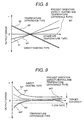
- FIG. 8 is a graph showing output errors caused by intake air temperature and an example of the characteristic correction.
- This embodiment intends to improve the temperature characteristic particularly when the output characteristics f1 and f2 are used by combining different characteristics.
- an output ft1 of the direct heating type heat-generating type
- an output ft2 of the temperature difference type is likely to have a negative temperature characteristic when the temperature detecting resistors are driven by a constant voltage.
- the characteristic of the output ft1 of the direct heating type can be changed by changing the temperature compensation resistor 17 in the bridge. In that case, however, the adjustment becomes complex because the temperature characteristics are not always uniform. In order to solve this problem, the temperature characteristics can be easily improved by executing digital operating correction to ch ange an error ratio to each temperature characteristic.
- each of the parameters can be set according to a ratio of change to temperature of intake air. For example, assuming that the output ft1 of the direct heating type is opposite in polarity to and twice as large as the output ft2 of the temperature difference type, characteristics qt1 and qt2 having temperature characteristics opposite to each other are obtained by adjusting the parameters of E quation 1 and Equation 2. By operating these using Equation 3, a characteristic qt3 having a good intake air temperature characteristic can be obtained.
- FIG. 9 is a graph showing output errors caused by flow rates and an example of the characteristic correction.
- This embodiment intends to improve the characteristic of flow rate dependency particularly when the output characteristics f1 and f2 are used by combining different characteristics.
- the figure shows the states of changes from the basic characteristic of the output corresponding to the flow rate caused by the surrounding temperature, variations in the devices etc.
- errors in both of the output fe1 of the direct heating type and the output fe2 of the temperature difference type become large in the low flow ra te side. The reason is that an allowable amount to variance decreases as the flow rate becomes smaller because of using a relative error for the evaluation, and therefore, the ratio of error increases even when the variance in appearance is the same.
- the flow rate dependency can be improved by adjusting the parameters similar to the case of the correction of the intake air temperature described above. For example, characteristics qe1 and qe2, which minimize the flow rate dependency of the output fe1 of the direct heating type to the output fe2, are obtained. By operating these using Equation 3, a characteristic qe3 having a good flow rate dependency can be obtained.
- the parameters of Equation 1 can be corrected to the output f1 of the di rect heating type as described below.
- the sensitivity can be improved by the digital ope rating means, and number of variables for the sensitivity correction can be reduced to simplify the adjustment.
- the sensitivity correction and the temperature correction according to the flow direction can be easi ly executed to improve the performance.
- the exhaust gas if the engine can be reduced because the accuracy of measuring the air flow rate is improved.
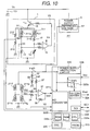
- FIG. 10 is a diagram showing a driving circuit of the thermal air flow meter in accordance with the present invention.
- This embodiment is an example in which the reference voltage circuit in the digital correction circuit 220 is arranged in the outside, compared to the embodiment of FIG. 1.
- the hot-wire drive circuit 1 is connected to the power supply 101, and outputs a signal corresponding to an air flow rate.
- the power source circuit 5 is also connected to the power supply 101, and a voltage Vref3 is produced by the reference voltage circuit 51.
- the voltage Vref3 is supplied as the electric power to the digital correction circuit 220 and to the bridge circuit composed of the temperature detecting resistors 221d, 221e, 221f and 221g.
- the electric potentials Vb1 and Vb2 of the bridge midpoints of the temperature detecting resistors 221d, 221e, 221f and 221g are inputted to the analog-digital converter 221c of the digital correction circuit 220 as a temperature difference voltage Vb3 which is amplified by resistors 32, 33, 34, 35, 36, 37 and a differential amplifier 31 in taking an offset voltage Voff as the reference.
- a voltage signal V2 obtained by converting the current flowing through the above-described heating resistor 211 a to a voltage by a resistor 13 and a voltage Vr1 obtained by dividing the applied voltage V1 of the bridge circuit of the hot-wire drive circuit 1 by resistors 212 and 213 are also inputted to the analog-digital converter 221c of the digital correction circuit 220.
- the analog-digital converter 221c converts a voltage value corresponding to the flow rate to a digital value in taking the voltage Vref3 generated by the reference voltage circuit 51 as the reference, and adjusts the digital value through operation, and then obtains an output voltage Vout from a digital-analog converter 224 to output the obtained signal to an engine control unit and so on.
- the digital-analog converter 224 is constructed so as to be switchable between the voltage Vref3 generated by the reference voltage circuit 51 and the external voltage Vcc using a switch 225b.
- the reason is that the reference can be freely selected when an analog value is used in the interfacing.
- the voltage Vcc is used as the reference.
- the independent reference voltage Vref3 is selected to make matching with the corresponding control unit easy and to make an error due to mismatching of the analog interface smaller.
- analog-digital converters 221a and 221b a single analog-digital converter is used by using a switch.
- an analog-digital converter of, for example, a successive comparison type may be used.
- the analog-digital converter 221c is constructed so as to be receivable of ground-based inputting, and capable of converting a positive analog input to a digital signal having no sign.
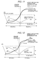
- FIG. 11 is a graph showing an example of operating correction of the characteristics of sensor output voltage versus bidirectional air flow rate.
- the characteristic of output versus flow rate obtained from the voltage signal V2 by converting the current flowing through the heating resistor 211a, described above, is expressed by f1
- the characteristic output versus flow rate obtained from the temperature difference voltage Vb3 obtained by amplifying the electric potentials Vb1 and Vb2 of the midpoints of the bridge composed of the temperature detecting resistors 211d, 211e, 211f and 211g in taking the offset voltage Voff as the reference is expressed by f2.
- the voltage obtained by dividing the voltage V1 applied to the bridge circuit using resistors 212 and 213 may be used for the output characteristic f1.
- a different point between the voltages V1 and V2 is difference in the temperature characteristic.
- the temperature characteristic is adjusted by a resistor 17, there is an advantage that the voltage V1 is easy to make the temperature dependency smaller compared to the voltage V2.
- heated temperature T h of the heating resistor 211a can be calculated by measuring a voltage between the both ends of the heating resistor 211a, and temperature compensation using the heated temperature Th may be employed in order to reduce the temperature dependency.
- the characteristic of output versus flow rate f2 can be obtained by increasing and decreasing the output corresponding to the flow direction.
- the output of the temperature difference type q2 is a positive output when the flow rate is positive to an offset flow rate q0, and a negative input when the flow rate is negative. Particularly, since the output does not have the sign, it is necessary to perform correction operation taking the offset flow rate q0 into consideration.
- the output of the direct heating type q1 is always positive when the flow rate is positive and when the flow rate is negative, and accordingly there is no need to take the flow direction into consideration.
- sensitivity-corrected q1 and q2 are obtained from the output characteristics f1 and f2 by Equation 1 and Equation 2 previously described.
- the range where the flow rate is positive is defined as a region a
- an output of the temperature difference type in this occasion is defined as q2a
- an output of the direct heating type in this occasion is defined as q1a.
- the range where the flow rate is negative is defined as a region b
- an output of the temperature difference type in this occasion is defined as q2b
- an output of the direct heating type in this occasion is defined as q1b.
- FIG. 12 is a graph showing an example of judging correction of the characteristics of sensor output voltage versus bidirectional air flow rate. As shown in FIG. 12, in this example, the sensitivity correction is performed by judging magnitude of values using the offset flow rate and the flow direction. Both of the above examples have the same effect as that of the aforementioned embodiment.
- the present embodiment there is the effect that even when the output characteristics f1 and f2 are different from each other and without sign, operation (calculation) equivalent to operation for the output characteristics with sign can be performed, and the sensitivity correction can be performed irrespective of the flow direction, and the performance can be improved. Further, there is the effect that the present embodiment can be easily realized even if a general-purpose microcomputer is used because the structure of the digital correction circuit 220 becomes simpler.
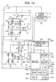
- FIG. 13 is a diagram of a driving circuit of the thermal air flow meter in accordance with the present invention. Even if the external voltage Vcc is directly inputted to the analog-digital converter 221c and the operation of the dependency of the external voltage is executed in the digital correction circuit 220, as shown in FIG. 13, it is possible to easily obtain the same effect as the effect of the aforementioned embodiments. Further, by imputing the voltage at the both ends of the temperature compensation resistor 211c to the digital correction circuit, the intake air temperature can be calculated, and the voltage can be used for the correction of the intake air temperature and the outpu t of the intake air temperature. In the present embodiment, an analog output of the intake air temperature is realized by providing the digital-analog converter 224b. According to the present embodiment, by using the analog-digital converter having a great number of channels, it is possible to obtain a higher accurate and high-performance air flow meter.
- FIG. 14 is a diagram of a driving circuit of the thermal air flow meter in accordance with the present invention.
- a resistor 211h having the same temperature coefficient as the temperature compensation resistor 211c, a thermistor or the like is used for one of the bleeder resistors, as shown in FIG. 14.
- the temperature characteristic of the output V1 may be improved in another manner. Different from the temperature characteristic of the temperature detecting resistors 211d, 211e, 211f and 211g, the temperature dependency of the output V1 can be more finely pre-changed to a desirable characteristic.
- the directional characteristic positive temperature characteristic or negative temperature characteristic
- the bleeder resistor 213 is arranged inside the digital correction circuit 220 or in a substrate mounting the digital correction circuit 220 though the temperature compensation resistor 211h is arranged inside the intake air passage, and a resistor having a temperature coefficient s Preble for detecting temperature of the substrate is used for the breeder resistor 213. By doing so, the effect of temperature of the substrate can be reduced.
- FIG. 15 is a graph showing temperature dependencies of the individual resistors to intake air temperature. As shown in FIG. 15, the original temperature characteristic vt1 of the direct heating type is improved by the temperature compensation resistor 211h to obtain a characteristic vta. On the other hand, an output vt3 compensated on both of the intake air temperature and the substrate temperature can be obtained from a characteristic vtm compensated on the substrate temperature.
- an output having a good temperature characteristic can be obtained.
- an air flow meter having a good temperature characteristic can be obtained even if an analog-digital converter having a small number of channels.
- FIG. 16 is a block diagram showing an example of operating correction and output of output-switching. Description will be made below on software processing of input-and-output in accordance with the present invention.
- characteristics of the signals f1 and f2 obtained from the analog-digital converters 311a and 311b are improved by digital operating correction processing 312 using the parameters a1, a2, b1 and b2, as described in the aforementioned embodiment, and thus a characteristic-improved signal q3 is obtained.
- the signal q3 is converted to an air flow rate by air flow rate conversion processing 313a, and thus an air flow rate converted signal qv3 is obtained.
- the air flow rate is obtained by converting a voltage to a flow rate using, for example, a table called as voltage-flow rate conversion map.
- the tables called as voltage-flow rate conversion maps may be prepared for individual sensors, or by using a typical characteristic, correction tables may be separately prepared for individual sensors. These tables are recorded in a memory element called as PROM which is writable once or more times, and can hold records without any power source.
- the signal q3 after operation and the signal qv3 converted to air flow rate are switched using a software switch 316a which can be operated by a signal from the external.
- an output fout converted to frequency by a pulse conversion processing 314 and a voltage value Vout converted by digital-analog conversion processing 315 are switched using software switches 316b and 316c.
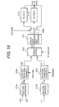
- FIG. 18 is a block diagram showing an example of operating correction and output of output-switching.
- voltages of the signals f1 and f2 obtained from the analog-digital converters 311a and 311b are converted to flow rates using tables called as voltage -flow rate maps shown in FIG. 19. Since the two signals are different in characteristics from each other, the tables are separately prepared.
- the signals qv2 and qv1 converted respectively through air flow rate conversion processing 313b and 313c are compensated through operation processing 312 to obtain a signal qv3 of which sensitivity of the output is compensated, similarly to in the aforementioned embodiment, and then the digital signal qv3 is converted to a duty of pulse signal through pulse conversion processing 314.
- the pulse signal is changed to a smoothed analog signal or a pulse output signal by switching a software switch 316d, which is switchable by a signal from the external, to select any one of filters 317a and 317b having characteristics different from each other and to a route without filter.
- a software switch 316d which is switchable by a signal from the external, to select any one of filters 317a and 317b having characteristics different from each other and to a route without filter.
- a software switch 316d which is switchable by a signal from the external, to select any one of filters 317a and 317b having characteristics different from each other and to a route without filter.
- a software switch 316d which is switchable by a signal from the external
- FIG. 21 is a block diagram showing an example of operating correction and switched output after conversion to air flow rate. Another kind of input-output software processing will be described below.
- voltages of the signals f1 and f2 obtained from the analog-digital converters 311a and 311b are converted to flow rates using tables called as voltage -flow rate maps shown in FIG. 19. Since the two signals are different in characteristics from each other, the tables are separately prepared.
- the signals qv2 and qv1 converted respectively through air flow rate conversion processing 313b and 313c are compensated through operation processing 312 to obtain a signal qv3 of which sensitivity of the output is compensated.
- FIG. 22 shows the output characteristics.
- interrelation among the two flow rate signals qv2 and qv1 and the ou tput qv3 processed through the operation processing can be adjusted by preparing a plurality of correction parameters k1, k2, k3, k4, ... . This is particularly effective for adjusting of the output, etc.
- One of the examples will be described below.
- the signals qv2 and qv1 having different sensitivity characteristics and different temperature characteristics in the initial characteristics are read as analog values using the software switch 316e, and then the signal qv3 corrected using the correction parameters a1, a2, b1, b2, k1, k2, k3, k4, ... is obtained.
- the signals qv2 and qv1 are dispersed, extraction of the parameters becomes easy. Therefore, signals having higher accuracy against sensitivity and temperature can be obtained.
- thermo air flow rate measuring apparatus and a thermal air flow mater having high accuracy, in which sensitivity is enhanced by an operating means using sensors having different output characteristics and employing a digitized signal, and the sensitivity and temperature can be corrected easily depending on the flow direction of fluid, and to provide an internal combustion engine and a thermal air flow rate measuring method using the thermal air flow rate measuring apparatus.
- an air flow meter having high sensitivity and high accuracy can be obtained by the digital correction described above, there is the effect that engine control for a vehicle can be optimized to reduce exhaust gas from the vehicle.
Landscapes
- Physics & Mathematics (AREA)
- Fluid Mechanics (AREA)
- General Physics & Mathematics (AREA)
- Measuring Volume Flow (AREA)
Abstract
A thermal air flow rate measuring apparatus of great precision is
disclosed. In the thermal air flow rate measuring apparatus, sensitivity is
enhanced by sensors having different output characteristics and an operating
means employing a digitized signal, and the sensitivity and temperature can be
corrected easily depending on the flow direction of fluid.
The measuring apparatus comprises at least one heating resistor
disposed in a gas fluid, temperature detecting resistors formed at an upstream
part and a downstream part of the heating resistor in the flow direction of the
fluid, a means for outputting at least two signals relating to the flow rate of the
fluid, a quantizing means for quantizing the output values, and an operating
means for operating the flow rate based on the quantized signals.
Description
The present invention relates to a novel thermal air flow rate measuring
apparatus and a novel thermal air flow rate measuring method, and to an
internal combustion engine using the thermal air flow rate measuring apparatus
and a thermal air flow rate measuring method suitable for detecting an intake
air flow rate of the internal combustion engine.
As an air flow rate apparatus for measuring an intake air flow rate
arranged in an electronically controlled fuel injection unit of an internal
combustion engine in a vehicle or the like, air flow rate measuring apparatuses
of thermal type have been widely used because of capability of directly
detecting a mass air flow rate. Therein, its heating resistor is constructed by
winding a platinum wire around a bobbin and then coating the wire with glass,
or by forming a thin film resistor on a ceramic substrate or a silicon substrate.
As the methods of detecting a flow rate, there are a type in which a
heating resistor is heated up to a given temperature and a flow rate is directly
detected from a value of current flowing through the resisto r when a fluid flows,
and a type in which temperature detecting resistors are arranged in both sides
of a heating resistor and a flow rate is detected from a temperature difference
between the temperature detecting resistors.
Particularly in vehicles, in a case of pulsating flow having a large
pulsating amplitude of an intake air flow rate and partial reversed flow, which
may take place under a low rotation speed and a heavy load condition in an
engine having four or less cylinders, the conventional air fl ow rate measuring
apparatus requires an output signal corresponding to the air flow direction
because the accuracy of the measured flow rate becomes poor. The type, in
which temperature detecting resistors are arranged in both sides of the heating
resistor and an air flow rate is detected from a temperature difference between
the temperature detecting resistors, is suitable for detecting an output signal
under the condition of existing of the reversed air flow because the output
signal corresponds to the flow direction.
Since each of the above two types has advantages and disadvantages
depending on the use, a type combining the above both types using an analog
circuit is disclosed in Japanese Patent Application Laid-Open No. 9-318412,
and in Japanese Patent Application Laid-Open No. 11-51954. That is, since the
temperature difference output signal having a comparatively high sensitivity is
deteriorated in a high flow rate side due to saturation of the sensitivity, the
temperature difference output signal is output by adding the output signal of the
direct detecting type having low sensitivity in the low flow rate side and high
sensitivity in the high flow rate side using a differential amplifier.
As methods of compensating the output signal of temperature
difference between the temperature detecting resistors having the
comparatively good sensitivity other than the above described method of
compensating the sensitivity, a method of compensating the output signal by
dividing by a temperature rise of a heater is disclosed in Japanese Patent
Publication No. 6-63801, and a method of compensating temperature is
disclosed in Japanese Patent Publication No. 6-64080.
In addition, as another method of compensating the output signal of
temperature difference between th e temperature detecting resistors particularly
for vehicles, a method of compensating the output signal by detecting
temperature of a medium is disclosed in Japanese Patent Application Laid-Open
No. 6-160142.
On the other hand, as digitized methods using an A/D converter, a
method of compensating a zero point depending on the output signal of a
temperature detecting resistor is disclosed in Japanese Patent Application
Laid-Open No. 6-230021. Further, a method of digitally compensating
temperature is disclo sed in Japanese Patent Application Laid-Open No. 11-94620.
In the prior art described above, particularly, as the methods of
compensating the accuracy of output signal of the temperature difference
between the temperature detecting resistors, various type s mainly using an
analog circuit have been proposed. In the analog circuit, various kinds of
devices different in the measuring range of flow rate corresponding to the uses
are required, and the circuits and the adjustments become complex in order to
improve the accuracy. Therefore, these increase the cost. Although the type of
digitally compensating the zero point or the type of digitally compensating
temperature has been studied, adjusting of sensitivity of the whole sensors has
not been considered.
An object of the present invention is to provide a thermal air flow rate
measuring apparatus and a thermal air flow mater having high accuracy, in
which sensitivity is enhanced by an operating means using sensors having
different output characteristics and employing a digitized signal, and the
sensitivity and temperature can be corrected easily depending on the flow
direction of fluid, and to provide an internal combustion engine and a thermal
air flow rate measuring method using the th ermal air flow rate measuring
apparatus.
The present invention is characterized by a thermal air flow rate
measuring apparatus comprising at least one heating resistor disposed in a gas
fluid, temperature detecting resistors formed at an upstream part and a
downstream part of the heating resistor in a flow direction of the fluid, an output
means for outputting at least two signals relating to a flow rate of said fluid from
the heating resistor and the temperature detecting resistors, a quantizing
means (a digitizing means) for quantizing (digital-converting) the output values,
and an operating means for operating the flow rate based on the quantized
signals; or a thermal air flow raxe measuring apparatus comprising an operating
means for operating the at le ast two quantized (digital-converted) signals using
at least two parameters, and a synthesizing and outputting means for
synthesizing the operated signals and outputting the synthesized result; or a
thermal air flow rate measuring apparatus comprising an o perating means for
operating the at least two quantized (digital-converted) signals using at least
two parameters, and an output means for synthesizing the operated signals
and outputting the synthesized result, wherein the two signals relating to the
flow rate are signals relating to a heat generating value of the heating resistor
and to a temperature difference between the temperature detecting resistors
formed at the upper stream part and the downstream part.
Further, the present invention is characteri zed by a thermal air flow rate
measuring apparatus comprising at least one heating resistor disposed in a gas
fluid, a flow rate detecting means for detecting a flow rate of the fluid using the
heating resistor by driving the heating resistor at a constant temperature using
a temperature compensating resistor; flow rate detecting means for detecting
the flow rate from a temperature difference between temperature detecting
resistors each arranged in both sides of the heating resistor; a quantizing
means (a digitizing means) for quantizing (digitizing) a value from the heating
resistor and a value according to the temperature difference; an operating
means for operating the quantized (digital-converted) values; and a correcting
means for correcting the operate d values.
Further, the present invention is characterized by a thermal air flow rate
measuring apparatus comprising at least one heating resistor disposed in a gas
fluid; temperature detecting resistors formed at an upper stream part and a
downstream part of the heating resistor in a flow direction of the fluid, the
temperature detecting resistors being arranged in multi-stage along a
longitudinal direction of the heating resistor individually at the upstream part
and the downstream part; in addition, an o utput means for outputting at least
two signals relating to a flow rate of the fluid from the heating resistor and the
temperature detecting resistors; a quantizing means for quantizing the output
values; and an operating means for operating the flow rater and directions of
the fluid based on the quantized signals.
The present invention is characterized by a thermal air flow rate
measuring method, which operates a flow rate and a flow direction of a gas
fluid based on a signal relating to an amount of heat generated by at least one
heating resistor disposed in the gas fluid; a signal relating to a temperature
difference between an upstream part and a downstream part of temperature
detecting resistors in a flow direction of the fluid, said temperature detect ing
resistors being formed in multistage respectively at the upstream part and the
downstream part of the heating resistor; and a signal relating to a flow
difference of the fluid other than the temperature difference, or, in addition to
these, based on quantized signals obtained by quantizing the signals described
above.
In other words, the present invention comprises a heating resistor; a
means for detecting a flow rate by driving the heating resistor at a constant
temperature using a temperature compensation resistor; a means for detecting
a flow rate from a temperature difference between temperature detecting
resistors by arranging the temperature detecting resistors in both sides of the
heating resistor; a quantizing means (a digitizing means) for inpu tting a signal
corresponding to the flow rate obtained from the heating resistor and a signal
corresponding to the flow rate obtained from the temperature difference; and a
means for quantizing-operating (digital-operating) the both signals to perform
correction and adjustment.
According to the present invention, even in a case where the air flow
rate measuring apparatus is used in different measuring ranges, the
measurement accuracy can be improved by using the two flow rate signals
different in the detection principles and easily adjusting the output sensitivity
through the digital optimization operation.
In the present invention, the function of the first or higher order
equation described above is expressed by any one of (q1 = a1 ×f1 + b1, q2 =
f2, ...), (q1 = f1, q2 = a2 ×f2 + b2, ...) and (q1 = a1 ×f1 + b1, q2 = a2 ×f2 + b2, ...),
and the function for temperature is expressed by (a1 = c1 ×Ta + d1, b1 = c2×Ta
+ d2, ...), and the function for the quantized signal is expressed by (a1 = g1 ×f1
+ h1, b1 = g2×f1 + h2, ...). A function of the second or third order may be
employed for each of the above functions.
According to the present invention, even in a case where the air flow
rate measuring apparatus is used in different measuring ranges, the
measurement accuracy can be improved by using the two flow rate signals
different in the detection principles and easily adjusting the output sensitivity
through the digital optimization operation.
In a hot-wire type air flow meter for measuring an intake air flow rate o f
an internal combustion engine used in a vehicle or the like, the present
invention provides devices different in the flow rate measuring ranges
corresponding to various uses, and improves the measurement accuracy by
adjusting the total sensitivity of sen sors, and simplifies the circuit and the
adj ustment.
By obtaining the air flow meter having high sensitivity and high
accuracy by executing the digital compensation described above, there is the
effect that amount of exhaust gas from an engine of a vehicl e can be reduced
by optimizing the engine control.
FIG. 1 is a diagram showing a drive circuit of a thermal air flow rate
measuring apparatus according to the present invenfion. A hot-wire drive circuit
1 is connected to a power source 101 to output a signal corresponding to an air
flow rate. The hot-wire drive circuit 1 comprises a Wheatstone bridge
composed of a heating resistor 211a, a temperature compensation resistor
211c and resistors 13, 14 and 17, and is constructed in such a manner that
current flowing through the heating resistor 211a can be controlled by a
differential amplifier 15 and a transistor 16 to make an electric potential
difference between the midpoints of the bridge zero. When the heated
temperature of the heating resistor 211a is low, an output of the differential
amplifier 15 becomes large so as to further heat up the heating resistor 211a.
By this construction, the resistance value of the heating resistor 211a is
controlled at a constant value independently of the flow rate, that is, the current
flowing through the heating resistor 211a is controlled so as to keep the
temperature at a constant value. At that time, as for the signal of the heating
resistor 211a corresponding to the air flow rate, a voltage signal V2 is obtained
by converting the current flowing through the heat ing resistor 211a to a voltage
by the resistor 13 and inputted to a digital correction circuit 220.
Therein, the heating resistor 211a may be constructed, for example, by
forming a thin film or a thick film made of platinum or tungsten as a heat-generator
on a glass plate or a ceramic substrate. Particularly, the heating
resistor 211a is a resistor in which a thin film or a thick film made of platinum or
tungsten as a heat-generator, or a poly-silicone resistor, or a single-crystal
silicon resistor is form ed on a semiconductor substrate made of silicon or the
like.
The heating resistor 211a is disposed inside an intake air passage of
an internal combustion engine for a vehicle etc to obtain the voltage output V2
corresponding to a flow rate of air flowing in the intake air passage.
On the other hand, an output corresponding to a direction of flow can
be obtained from the method that temperature detecting resistors 211d, 211e,
211f and 211g are arranged in the both sides of the heating resistor 211a to
form a bridge by the temperature detecting resistors 211d, 211e, 211f and 211g,
and then a temperature difference between the resistors is detected from a
difference between voltage potentials at midpoints. Therein, the temperature
detecting resistors 211d, 211e, 211f and 211g are driven at a constant voltage
by a power supply voltage Vref1. The method of detecting the temperature
difference between the resistors is high in the sensitivity in the low flow rate
side because of using deferential detection and suitable for detecting a
bidirectional flow such as back flow, but the sensitivity in the high flow rate side
is apt to be limited because of being driven at the constant voltage.
FIG. 2 is a view showing an example of a pattern in which the heating
resistor 211a of thin film is formed on a silicon semiconductor substrate. The
heating resistor 211 a is formed in an oblong shape with a back-and-forth
turned pattern of the resistance thin-film wire, and the temperature detecting
resistors 211d, 211e, 211f and 211g are arranged in the both sides of the
heating resistor. The heating resistor 211a and the temperature detecting
resistors 211d, 211e, 211f and 211g are arranged in a diaphragm structure part
of the silicon substrate 211, the diaphragm structure part being formed, for
example, by etching the substrate from the back face, and having a small
thermal capacity. A temperature compensation resistor 211c is arranged at a
position insensitive to temperature rise caused by heat generation of the
heating resistor 211a.
The principle of detecting a flow rate from a temperature difference will
be described below in detail. In FIG. 2, air normally flows from A toward B.
Even when there is no air flow, a temperature distribution is caused in the
heater by being heated by the heating resistor 211a. Under a condition of no
air flow, since all the resistance values of the temperature detecting resistor s
211d, 211e, 211f and 211g are the same, no output is generated even when
the bridge circuit is formed. When air flow take s place, the temperature
distributions in the both sides of the heating resistor 211a are changed to
obtain an output corresponding to an air flow rate. In more detail, the resistance
values of the temperature detecting resistor s 211d and 211e in the upstream
side of the heating resistor 211a are decreased because their temperatures are
decrease, and the resistance values of the temperature detecting resistors 211f
and 211g in the downstream side are increased because their temperatures
are increase by receiving heat from the heating resistor 211a, and thus the
produced temperature difference between the upstream side and the
downstream side can be obtained as the change in the resistance values.
As described above, by forming the bridge using the plurality of
temperature detecting resistors arranged in the longitudinal direction of the
heating resistor 211a, the sensitivity of detecting the temperature difference
can be improved. From the principle, even when two temperature detecting
resistors are arranged in the upstream side and the downstream side,
respectively, and a bridge is constructed using the two temperature detecting
resistors by combining with two resistors particularly insensitive to temperature,
the same detection can be performed. However, the sensitivity of output
voltage to change in the temperature detecting resistors decreases lower
compared to the case where the plurality of temperature detecting resistors are
arranged in the longitudinal direction of the heating resistor 211a, described
above. In a case where the temperature dependency of the temperature
detecting resistors is high, two temperature detecting resistors in total may be
arranged each in the upstream side and the downstream side. However, in a
case where the temperature depen dency of the temperature detecting resistors
is high, and accordingly, sufficient output sensitivity can not be obtained, it is
preferable that a plurality of, particularly two, temperature detecting resistors
are arranged respectively in the upstream side and the downstream side.
FIG. 3 is a cross-sectional view of the resistors formed on the silicon
substrate. The area having the resistor patterns is constructed so as to have
the thickest substrate. In the present embodiment, the electric potentials Vb1
and Vb2 of the midpoints of the bridge composed of the temperature detecting
resistors 211d, 211e, 211f and 211g are also inputted to the digital correction
circuit 220. The digital correction circuit 220 has two analog- digital converters
221a and 221b, and reads a voltage corresponding to the flow rate by
converting the voltage to a digital value, and adjusts the digital value through
operation, and then obtains an output voltage Vout from a digital-analog
converter 224 to output the obtained signal to an engine control unit and so on.
Therein, the digital correction circuit 220 comprises an operation (calculation)
circuit 222 composed of a CPU 222a, a RAM 222b and a ROM 222c; an
oscillator 226; a PROM 223; and so on. The PROM 223 may be any memory
capable of storing variations in output sensitivities of individual sensors once or
more times as adjusting values, and therefore, is not limited to an electrically
rewritable EEPROM, a flash ROM or the like.
Further, by inputting a voltage Vcc supplied from the external to an
internal power supply/protection circuit 228 as a power supply, a power supply
voltage Vref1 dependent on the external voltage Vcc is used as the reference
voltage by connecting the power supply/protection circuit 228 to the analog- digital
converters 221a and 221b, the digital-analog converter 224 through
switches 225a and 225b. The switches 225a and 225b are for switching
between a voltage Vref2 generated by a reference voltage circuit 229 inside the
digital correction circuit 220 and the po wer supply voltage Vref1 depending on
the external voltage Vcc described above. Therein, the analog- digital
converters 221a and 221b are required to be high accurate because the
outputs Vb1, Vb2, V2 etc of the bridge circuits are directly inputted. In orde r to
secure the high accuracy and to make the size of the circuit small, it is
preferable to employ a..-type analog-digital converter.
In the present embodiment, the analog-digital converters are provided
separately for digitizing the voltage signal V2 obtained by converting the
current flowing through the heating resistor 211a to a voltage using a resis tor
13 and for digitizing the electric potentials Vb1 and Vb2 of the midpoints of the
bridges composed of the temperature detecting resistors 211d, 211e, 211f and
211g showing a temperature difference corresponding to a flow rate. The
reason is that both of the principles for detecting flow rate are different from
each other, and that each of the constructions can be easily optimized.
The voltage signal V2 is for controlling the bridge voltage of the hot-wire
drive circuit 1 by feedback, and the output is independent of the power
source voltage Vcc of the digital correction circuit 220 etc. Since an
independent reference voltage is, therefore, required for the analog-digital
conversion, the reference voltage Vref2 is provided to apply to the analog-digital
converter 221b as the reference.
On the other hand, although the temperature detecting resistors 211d,
211e, 211f and 211g are driven at a constant voltage by the power supply
voltage Vref1, the electric potentials Vb1 and Vb2 of the bridge midpoints are
increased and decreased by fluctuations of the power supply voltage Vref1.
One of the methods of removing this phenomenon is that the power supply
voltage Vref1 is used as the reference voltage of the analog-digital converter
221a, and at the digital conve rsion, a read value is changed similarly to the
fluctuations of the power supply voltage Vref1. Particularly, the present
embodiment is constructed so that the reference voltage of the analog-digital
converter 221a can be switched by providing the switch 225a. When the
fluctuations in the power supply voltage is very small, a reference voltage Vref2
of a reference voltage circuit 229 may be used for the reference voltage of the
analog-digital converter 221a.
Further, the digital -analog converter 224 is sim ilarly constructed so that
the reference voltage can be changed by the switch 225b. The reason is that
the reference can be freely selected when an analog value is used in the
interfacing. In a case where the reference voltage of the analog-digital
converter in the side of a connected control unit and the voltage Vcc supplied
from the external are similar to each other or fluctuate in synchronism with each
other, the power supply voltage Vref1 is used as the reference. In a case where
there is no relation between the reference voltage of the analog-digital
converter in the control unit side and the voltage Vcc, the independent
reference voltage Vref2 is selected to make matching with the corresponding
control unit easy and to make an error due to mismatching of the analog
interface smaller.
By constructing the digital correction circuit 220 as described above,
the output sensitivity can be improved, and an air flow meter easy in adjustment
can be obtained. The detailed operation will be described below, refe rring to
FIG. 4. In FIG. 4, the characteristic of output versus flow rate obtained from the
voltage signal V2 by converting the current flowing through the heating resistor
211a, described above, is expressed by a curve f1, and the characteristic
output versus flow rate obtained from the voltage difference dV between the
electric potentials Vb1 and Vb2 of the bridge midpoints, which shows the
temperature difference corresponding to fhe flow rate obtained by the
temperature detecting resistors 211d, 211e, 211f and 211g, is expressed by a
curve f2.
Since the heating current of the heating resistor 211a is flowing even in
the condition of zero flow, the output characteristic curve f1 becomes an offset
output voltage characteristic curve which does not pass thr ough the origin. The
zero point of the output characteristic curve is apt to fluctuate due to natural
convection under self-heating in the condition of zero flow, but the output
characteristic curve does not saturate in the high flow rate region within a
range allowed by the power supply voltage. Therefore, in a case of using the
heating resistor 211a having a small heat capacity, the sensitivity, particularly,
in the low flow rate side is degraded, but the sensitivity in the high flow rate
side is high.
On the other hand, the output characteristic curve f2 ideally passes
through the origin at the zero flow because the output voltage is the difference
between the electric potentials at the bridge midpoints. The sensitivity,
particularly, from the zero flow to the low flow rate side is high, but the output
voltage in the high flow rate side changes smaller to saturate because the
difference between temperatures of the resistors becomes small.
In order to actually deal with the characteristics described above , a
zero-span adjustment, in which the zero point is adjusted by amplifying it using
a differential amplifier or the like, is generally performed through an analog
method. By doing so, the sensitivity characteristic may be improved in
appearance, but the essential sensitivities of the output voltage characteristics
f1 and f2 are not changed. In other words, there are the contradicting
characteristics that the characteristic f1 has the low sensitivity in the low flow
rate but the high sensitivity to the high flow rate side, and that the characteristic
f2 has the high sensitivity to the low flow rate but the low sensitivity in the high
flow rate side. In order to improve these characteristics, it can be considered
that the characteristics are changed using an analog operating (calculating)
circuit composed of differential amplifiers etc. However, performing of complex
analog operation (calculation) to compensate the sensitivities and performing
of adjustment in analog ways to compensate differences among the in dividual
sensors make the adjusting circuits and the adjusting methods complex to
increase the apparatus cost.
The object to solve the above-described problems can be attained by
performing digital operation (calculation) using the digital correction circ uit 220
described above. In the concrete, the sensitivities of the output characteristics
f1 and f2 are individually corrected using functions of the first or higher order
equation.
q1 = a1.f1 + b1
q2 = a2.f2 + b2
Then, the above sensitivity-corrected results are multiplied together.
q3 = q1.q2
As the result, it is possible to obtain a better sensitivity characteristic
from the low flow rate side to the high flow rate side compared to the essential
sensitivities of the output characteristics f1 and f2. As shown in FIG. 5, in order
to actually use the calculated result of (Equation 3), further adjustment of the
output level is required at interfacing.
 where, A = ga.a1.a2, B = ga.a1.b2, C = ga.a2.b1, and D = ga.b1.b2 +
off.
where, A = ga.a1.a2, B = ga.a1.b2, C = ga.a2.b1, and D = ga.b1.b2 +
off.
As described above, by providing the digital correction means, the
essential sensitive correction and output correction of the sensors can be
easily performed at a time. The calculation may be performed successively
from Equation 1 to Equation 4 described above, or the calculation may be
performed in single processing as shown by Equation 5. In the case of
Equation 5, if the parameters are calculated in advance and the results are
stored, it is advantageous that numb er of variables can be reduced compared
to the case where the correction parameters are individually stored.
According to the present embodiment, there is the effect that in the
case of using the sensors different particularly in the output characteristics f1
and f2, the sensitivity can be improved by the digital operating (calculating)
means, and number of variables for the sensitivity correction can be reduced to
simplify the adjustment.
FIG. 6 is a graph showing an embodiment of correction of the output
voltage characteristics of the sensors in accordance with the present invention.
The embodiment is in a case where the digital correcting means is used in
taking the flowing direction of air flow rate. The characteristic f2 of output
versus flow rate obtained from the voltage difference dV between the electric
potentials Vb1 and Vb2 of the bridge midpoints, which shows the temperature
difference corresponding to the flow rate obtained by the temperature detecting
resistors 211d, 211e, 211f and 211g, gives an output value having a sign
depending on the flowing direction. Fig. 6 shows the sensitivity-corrected
outputs q1 and q2 which are obtained by correcting the output characteristics
f1 and f2 using the above-described functions.
The output q2 of the temperature difference type is a positive output
value when the flow rate is positive, and is a negative output value when the
flow rate is negative. This can be attained in a case where, for example, the
analog-digital converter 221a of the digital correction circuit 220 is constructed
so as to be receivable of differential -inputting and capable of converting a
positive / negative analog differential input to a digital signal having a sign.
Particularly, in a case where the sensitivity is different depending on the flow
direction, the correction of the output characteristics can be optimized by
preparing a plurality of parameters a2u, b2u, a2d and b2d for the parameters
a2 and b2 in Equation 2 to change the sensitivity corresponding to the flow
direction.
On the other hand, the output q1 of the direct heating type (heat-generating
type) is always a positive output value irrespective of the positive or
negative flow rate, and accordingly, has no sign. This can be attained in a case
where, for example, the analog-digital converter 221b of the digital correction
circuit 220 is constructed so as to be receivable of ground -based inputting and
capable of converting a positive analog input to a digital signal having no sign.
In this case, particularly in Equation 1, the sensitivity is adjusted using the
parameters a1 and b1 so that the zero point of q2 and the zero point of q1 may
agree with each other.
In the above case of using the output q2 having a sign of the
temperature difference type and the output q1 having n o sign of the direct
heating type, the operation (calculation) of sensitivity correction may be also
executed using Equation 3, as in the above embodiment described above, but
the multiplied result q3 needs to have a sign.
According to the present embodiment, there is the effect that even in
the case where the output characteristics f1 and f2 are different from each
other and different in sign such as the outputs with sign and the outputs without
sign, sign-added calculation can be easily executed by the correction through
the digital processing, and the sensitivity can be corrected irrespective of the
flow direction of the flow rate, and accordingly the performance can be
improved.
FIG. 7 is a graph showing the relationship between the sensor output
voltage and the flow rate when the digital correcting means is used in taking
the flow direction of air flow rate into consideration. The output q2 of the
temperature difference type can be obtained as a signal with a sign
corresponding to the flow direction, as described above. On the other hand, the
output q1 of the direct heating type does not have the sign irrespective of the
flow direction. However, in this case, particularly in Equation 1, the sensitivity is
adjusted using the parameters a1 and b1 so that the output q1 may exceed the
output q2 of the temperature difference type in the high flow rate side, and the
zero point of q2 and the zero point of q1 may agree with each other. Further, by
checking the sign attached to the output q2 of the temperature di fference type,
an output -q1, which is obtained by attaching the sign to the output q1 of the
direct heating type, is prepared when the flow rate is negative.
In order to make the sensitivity in the low flow rate side and the
sensitivity in the high flow rate side compatible with each other, it is judged
which is larger, the output q2 of the temperature difference type or the output
q1 of the direct heating type. This is realized by a conditional judgment in which,
for example, the larger one is selected w hen the flow rate is positive, and the
smaller one is selected when the flow rate is negative. In this case, the
judgment is as follows.
q1 > 0, q2 . q1 q3 = q2
q1 > 0, q1 > q2 q3 = q1
q1 . 0, -q2 . -q1 -q3 = -q2
q1 . 0, -q1 < -q1 -q3 = q1
Therein, the minus symbol expresses an output with a sign. By
optimizing the parameters, the flow rate output q3 selected corresponding to
the flow rates can be expressed by a smooth curve having small steps at
switching time. Further, the multiplying processing as shown by Equation 3
previously described can be omitted by the judging operation.
According to the present embodiment, there are effects that even in the
case where the output characteristics f1 and f2 are different from each other
and different in sign such as the outputs with sign and the outputs without sign,
the sensitivity can be corrected by the digital correction and judgment means,
and accordingly the performance can be easily impro ved.
FIG. 8 is a graph showing output errors caused by intake air
temperature and an example of the characteristic correction. This embodiment
intends to improve the temperature characteristic particularly when the output
characteristics f1 and f2 are used by combining different characteristics. In
considering output errors when temperature of the intake air is changed from
normal temperature, an output ft1 of the direct heating type (heat-generating
type) is likely to have a positive temperature character istic to the intake air
temperature because the heating temperature is increased corresponding to
the temperature of intake air. On the other hand, an output ft2 of the
temperature difference type is likely to have a negative temperature
characteristic when the temperature detecting resistors are driven by a
constant voltage. Among these temperature characteristics, the characteristic
of the output ft1 of the direct heating type can be changed by changing the
temperature compensation resistor 17 in the bridge. In that case, however, the
adjustment becomes complex because the temperature characteristics are not
always uniform. In order to solve this problem, the temperature characteristics
can be easily improved by executing digital operating correction to ch ange an
error ratio to each temperature characteristic.
That is, in Equation 1 and Equation 2 previously described, each of the
parameters can be set according to a ratio of change to temperature of intake
air. For example, assuming that the output ft1 of the direct heating type is
opposite in polarity to and twice as large as the output ft2 of the temperature
difference type, characteristics qt1 and qt2 having temperature characteristics
opposite to each other are obtained by adjusting the parameters of E quation 1
and Equation 2. By operating these using Equation 3, a characteristic qt3
having a good intake air temperature characteristic can be obtained. The
parameters of Equation 1 can be corrected to the intake air temperature Ta, for
example, as described below.
a1 = c1.Ta + d1
b1 = c2.Ta + d2
According to the present embodiment, there are effects that even in the
case where the output characteristics f1 and f2 are different from each other
and the temperature characteristics are different each other, the temperature
characteristic performance can be corrected by the digital correction means.
FIG. 9 is a graph showing output errors caused by flow rates and an
example of the characteristic correction. This embodiment intends to improve
the characteristic of flow rate dependency particularly when the output
characteristics f1 and f2 are used by combining different characteristics. The
figure shows the states of changes from the basic characteristic of the output
corresponding to the flow rate caused by the surrounding temperature,
variations in the devices etc. In general, errors in both of the output fe1 of the
direct heating type and the output fe2 of the temperature difference type
become large in the low flow ra te side. The reason is that an allowable amount
to variance decreases as the flow rate becomes smaller because of using a
relative error for the evaluation, and therefore, the ratio of error increases even
when the variance in appearance is the same. Even in such a case, the flow
rate dependency can be improved by adjusting the parameters similar to the
case of the correction of the intake air temperature described above. For
example, characteristics qe1 and qe2, which minimize the flow rate
dependency of the output fe1 of the direct heating type to the output fe2, are
obtained. By operating these using Equation 3, a characteristic qe3 having a
good flow rate dependency can be obtained. The parameters of Equation 1 can
be corrected to the output f1 of the di rect heating type as described below.
a1 = g1.f1 + h1
b1 = g2.f1 + h2
By calculating parameters optimum to each of the characteristics in
advance and then executing the digital correction using the parameters
optimum to each of the sensors, as described above, it is possible to obtain an
air flow meter having optimum sensitivity, a good intake air temperature
characteristic and a good flow rate dependency.
According to the present embodiment, there are effects tha t by using
the sensors different particularly in the output characteristics f1 and f2 and
optimizing the individual use condition of the sensors using the digital
correction means, it is possible to obtain an air flow meter having optimum
sensitivity, a good intake air temperature characteristic and a good flow rate
dependency.
There is a remarkable effect that in the case of using the sensors
different particularly in the output characteristics f1 and f2, the sensitivity can
be improved by the digital ope rating means, and number of variables for the
sensitivity correction can be reduced to simplify the adjustment. At the same
time, there is the effect that the sensitivity correction and the temperature
correction according to the flow direction can be easi ly executed to improve the
performance. Further, there is the effect that when the air flow meter is used for
controlling an engine of a vehicle, the exhaust gas if the engine can be reduced
because the accuracy of measuring the air flow rate is improved.
FIG. 10 is a diagram showing a driving circuit of the thermal air flow
meter in accordance with the present invention. This embodiment is an
example in which the reference voltage circuit in the digital correction circuit
220 is arranged in the outside, compared to the embodiment of FIG. 1. The hot-wire
drive circuit 1 is connected to the power supply 101, and outputs a signal
corresponding to an air flow rate. The power source circuit 5 is also connected
to the power supply 101, and a voltage Vref3 is produced by the reference
voltage circuit 51. The voltage Vref3 is supplied as the electric power to the
digital correction circuit 220 and to the bridge circuit composed of the
temperature detecting resistors 221d, 221e, 221f and 221g.
In the present embodiment, the electric potentials Vb1 and Vb2 of the
bridge midpoints of the temperature detecting resistors 221d, 221e, 221f and
221g are inputted to the analog-digital converter 221c of the digital correction
circuit 220 as a temperature difference voltage Vb3 which is amplified by
resistors 32, 33, 34, 35, 36, 37 and a differential amplifier 31 in taking an offset
voltage Voff as the reference.
Further, a voltage signal V2 obtained by converting the current flowing
through the above-described heating resistor 211 a to a voltage by a resistor 13
and a voltage Vr1 obtained by dividing the applied voltage V1 of the bridge
circuit of the hot-wire drive circuit 1 by resistors 212 and 213 are also inputted
to the analog-digital converter 221c of the digital correction circuit 220. The
analog-digital converter 221c converts a voltage value corresponding to the
flow rate to a digital value in taking the voltage Vref3 generated by the
reference voltage circuit 51 as the reference, and adjusts the digital value
through operation, and then obtains an output voltage Vout from a digital-analog
converter 224 to output the obtained signal to an engine control unit
and so on.
Therein, the digital-analog converter 224 is constructed so as to be
switchable between the voltage Vref3 generated by the reference voltage
circuit 51 and the external voltage Vcc using a switch 225b. The reason is that
the reference can be freely selected when an analog value is used in the
interfacing. In a case where the reference voltage of the analog-digital
converter in the side of a connected control unit and the voltage Vcc supplied
from the external are similar to each other or fluctuate in synchronism with each
other, the voltage Vcc is used as the reference. In a case where there is no
relation between the reference voltage of the analog-digital converter in the
control unit side and the voltage Vcc, the independent reference voltage Vref3
is selected to make matching with the corresponding control unit easy and to
make an error due to mismatching of the analog interface smaller.
Therein, since number of input ports becomes large, it is preferable that
instead of using the analog- digital converters 221a and 221b, a single analog-digital
converter is used by using a switch. In orde r to secure the converting
speed and to make the circuit size smaller, an analog-digital converter of, for
example, a successive comparison type may be used. In this case, the analog-digital
converter 221c is constructed so as to be receivable of ground-based
inputting, and capable of converting a positive analog input to a digital signal
having no sign.
FIG. 11 is a graph showing an example of operating correction of the
characteristics of sensor output voltage versus bidirectional air flow rate. By
constructing the digital correction circuit 220 as described above, the output
sensitivity can be improved similarly to the previous embodiment, and it is
possible to obtain an air flow meter easy to adjust and having a smaller circuit
size. The characteristic of output versus flow rate obtained from the voltage
signal V2 by converting the current flowing through the heating resistor 211a,
described above, is expressed by f1, and the characteristic output versus flow
rate obtained from the temperature difference voltage Vb3 obtained by
amplifying the electric potentials Vb1 and Vb2 of the midpoints of the bridge
composed of the temperature detecting resistors 211d, 211e, 211f and 211g in
taking the offset voltage Voff as the reference is expressed by f2.
Therein, instead of using the voltage signal V2, the voltage obtained by
dividing the voltage V1 applied to the bridge circuit using resistors 212 and 213
may be used for the output characteristic f1. A different point between the
voltages V1 and V2 is difference in the temperature characteristic. Although the
temperature characteristic is adjusted by a resistor 17, there is an advantage
that the voltage V1 is easy to make the temperature dependency smaller
compared to the voltage V2. Further, heated temperature T h of the heating
resistor 211a can be calculated by measuring a voltage between the both ends
of the heating resistor 211a, and temperature compensation using the heated
temperature Th may be employed in order to reduce the temperature
dependency. In this case, the calculation of each parameter is as follows.
a1= c1.Th + d1
b1= c2.Th + d2
The characteristic of output versus flow rate f2 can be obtained by
increasing and decreasing the output corresponding to the flow direction. The
output of the temperature difference type q2 is a positive output when the flow
rate is positive to an offset flow rate q0, and a negative input when the flow rate
is negative. Particularly, since the output does not have the sign, it is
necessary to perform correction operation taking the offset flow rate q0 into
consideration. The output of the direct heating type q1 is always positive when
the flow rate is positive and when the flow rate is negative, and accordingly
there is no need to take the flow direction into consideration.
In the case of using the output of the temperature difference type q2
without sign and offset described above and the output of the direct heating
type q1 without sign, it is necessary to perform correction operation taking the
flow direction into consideration.
As an example, sensitivity-corrected q1 and q2 are obtained from the
output characteristics f1 and f2 by Equation 1 and Equation 2 previously
described. Here, the range where the flow rate is positive is defined as a region
a, an output of the temperature difference type in this occasion is defined as
q2a, and an output of the direct heating type in this occasion is defined as q1a.
Further, the range where the flow rate is negative is defined as a region b, an
output of the temperature difference type in this occasion is defined as q2b,
and an output of the direct heating type in this occasion is defined as q1b.
Calculation of the corrected output obtained by multiplying these outputs is
executed by separating condition according to the flow rate.
q2 > q0 q3 = q1a.(q2a - q0)
q2 . q0 q3 = q0 - (q1 b.(q0 - q2b)
FIG. 12 is a graph showing an example of judging correction of the
characteristics of sensor output voltage versus bidirectional air flow rate. As
shown in FIG. 12, in this example, the sensitivity correction is performed by
judging magnitude of values using the offset flow rate and the flow direction.
Both of the above examples have the same effect as that of the aforementioned
embodiment.
According to the present embodiment, there is the effect that even
when the output characteristics f1 and f2 are different from each other and
without sign, operation (calculation) equivalent to operation for the output
characteristics with sign can be performed, and the sensitivity correction can be
performed irrespective of the flow direction, and the performance can be
improved. Further, there is the effect that the present embodiment can be
easily realized even if a general-purpose microcomputer is used because the
structure of the digital correction circuit 220 becomes simpler.
FIG. 13 is a diagram of a driving circuit of the thermal air flow meter in
accordance with the present invention. Even if the external voltage Vcc is
directly inputted to the analog-digital converter 221c and the operation of the
dependency of the external voltage is executed in the digital correction circuit
220, as shown in FIG. 13, it is possible to easily obtain the same effect as the
effect of the aforementioned embodiments. Further, by imputing the voltage at
the both ends of the temperature compensation resistor 211c to the digital
correction circuit, the intake air temperature can be calculated, and the voltage
can be used for the correction of the intake air temperature and the outpu t of
the intake air temperature. In the present embodiment, an analog output of the
intake air temperature is realized by providing the digital-analog converter 224b.
According to the present embodiment, by using the analog-digital converter
having a great number of channels, it is possible to obtain a higher accurate
and high-performance air flow meter.
FIG. 14 is a diagram of a driving circuit of the thermal air flow meter in
accordance with the present invention. When the bridge voltage is detected by
dividing the voltage, a resistor 211h having the same temperature coefficient as
the temperature compensation resistor 211c, a thermistor or the like is used for
one of the bleeder resistors, as shown in FIG. 14. By such a construction, the
temperature characteristic of the output V1 may be improved in another manner.
Different from the temperature characteristic of the temperature detecting
resistors 211d, 211e, 211f and 211g, the temperature dependency of the output
V1 can be more finely pre-changed to a desirable characteristic. By changing
the configuration of the bleeder resistors, the directional characteristic (positive
temperature characteristic or negative temperature characteristic) may be
changed. Further, the bleeder resistor 213 is arranged inside the digital
correction circuit 220 or in a substrate mounting the digital correction circuit
220 though the temperature compensation resistor 211h is arranged inside the
intake air passage, and a resistor having a temperature coefficient s uitable for
detecting temperature of the substrate is used for the breeder resistor 213. By
doing so, the effect of temperature of the substrate can be reduced.
FIG. 15 is a graph showing temperature dependencies of the individual
resistors to intake air temperature. As shown in FIG. 15, the original
temperature characteristic vt1 of the direct heating type is improved by the
temperature compensation resistor 211h to obtain a characteristic vta. On the
other hand, an output vt3 compensated on both of the intake air temperature
and the substrate temperature can be obtained from a characteristic vtm
compensated on the substrate temperature.
By operating the above results in the digital correction circuit 220, an
output having a good temperature characteristic can be obtained. In the
present embodiment, by providing the resistor 211h depending on the intake air
temperature to pre-compensate the intake air temperature, an air flow meter
having a good temperature characteristic can be obtained even if an analog-digital
converter having a small number of channels.
FIG. 16 is a block diagram showing an example of operating correction
and output of output-switching. Description will be made below on software
processing of input-and-output in accordance with the present invention.
Referring to FIG. 16, characteristics of the signals f1 and f2 obtained from the
analog- digital converters 311a and 311b are improved by digital operating
correction processing 312 using the parameters a1, a2, b1 and b2, as
described in the aforementioned embodiment, and thus a characteristic-improved
signal q3 is obtained. The signal q3 is converted to an air flow rate by
air flow rate conversion processing 313a, and thus an air flow rate converted
signal qv3 is obtained. Therein, the air flow rate is obtained by converting a
voltage to a flow rate using, for example, a table called as voltage-flow rate
conversion map. The tables called as voltage-flow rate conversion maps may
be prepared for individual sensors, or by using a typical characteristic,
correction tables may be separately prepared for individual sensors. These
tables are recorded in a memory element called as PROM which is writable
once or more times, and can hold records without any power source.
In the present embodiment, in regard to the signals, the signal q3 after
operation and the signal qv3 converted to air flow rate are switched using a
software switch 316a which can be operated by a signal from the external. In
regard to output, an output fout converted to frequency by a pulse conversion
processing 314 and a voltage value Vout converted by digital-analog
conversion processing 315 are switched using software switches 316b and
316c. By switching as described above, outputs shown in FIG. 17 can be
arbitrarily obtained. This function can be easily realized by digitization, and a
plurality of output interfaces can be realized by the single digital correction
circuit 220. Therefore, the present embodiment has the effect that commonality
of components and accordingly cost reduction can be achieved.
FIG. 18 is a block diagram showing an example of operating correction
and output of output-switching. Referring to FIG. 18, voltages of the signals f1
and f2 obtained from the analog- digital converters 311a and 311b are
converted to flow rates using tables called as voltage -flow rate maps shown in
FIG. 19. Since the two signals are different in characteristics from each other,
the tables are separately prepared. The signals qv2 and qv1 converted
respectively through air flow rate conversion processing 313b and 313c are
compensated through operation processing 312 to obtain a signal qv3 of which
sensitivity of the output is compensated, similarly to in the aforementioned
embodiment, and then the digital signal qv3 is converted to a duty of pulse
signal through pulse conversion processing 314. The pulse signal is changed
to a smoothed analog signal or a pulse output signal by switching a software
switch 316d, which is switchable by a signal from the external, to select any
one of filters 317a and 317b having characteristics different from each other
and to a route without filter. Particularly, by changing the filter characteristic
depending on use of the output signal, an accurate analog output can be
obtained. Since the relationship between the accuracy and the response
generally becomes trade-off when such a pulse signal is fitter-converted, the
digitalization can easily cope with a case of requiring high accuracy and a case
of requiring a high response. FIG. 20 is graphs showing an example of the
output characteristics. Referring to the graphs, both of the duty . and the
output voltage have a similar linear relationship of output signal versus flow
rate. From the above results, the present embodiment has the effect that highly
accurate outputs can be obtained at low cost.
FIG. 21 is a block diagram showing an example of operating correction
and switched output after conversion to air flow rate. Another kind of input-output
software processing will be described below. Referring to FIG. 21,
voltages of the signals f1 and f2 obtained from the analog- digital converters
311a and 311b are converted to flow rates using tables called as voltage -flow
rate maps shown in FIG. 19. Since the two signals are different in
characteristics from each other, the tables are separately prepared. The signals
qv2 and qv1 converted respectively through air flow rate conversion processing
313b and 313c are compensated through operation processing 312 to obtain a
signal qv3 of which sensitivity of the output is compensated.
Then one of the three different air flow rates qv1, qv2 and qv3 is selected by a
software switch 316e, which is switchable by a signal from the external, to be
processed through digital-analog conversion processing 315. Thus, one of the
three flow rates can be obtained as a voltage analog value Vout. FIG. 22 shows
the output characteristics. In the operation (calculation) processing 312,
interrelation among the two flow rate signals qv2 and qv1 and the ou tput qv3
processed through the operation processing can be adjusted by preparing a
plurality of correction parameters k1, k2, k3, k4, ... . This is particularly effective
for adjusting of the output, etc. One of the examples will be described below.
The signals qv2 and qv1 having different sensitivity characteristics and
different temperature characteristics in the initial characteristics are read as
analog values using the software switch 316e, and then the signal qv3
corrected using the correction parameters a1, a2, b1, b2, k1, k2, k3, k4, ... is
obtained. Particularly when the signals qv2 and qv1 are dispersed, extraction of
the parameters becomes easy. Therefore, signals having higher accuracy
against sensitivity and temperature can be obtained.
In this processing, since the signals qv2, qv1 and qv3 are separately
obtained particuiarty when the characteristics are changed by fouling, the
correction of errors and the re-adjustment can be performed easily, and the
long-term characteristics can be compensated. In the present embodiment,
highly accurate sensors can be provided at low cost by the higher -level
adjustment.
Since an air flow meter having high sensitivity and high accuracy can
be obtained by the digital correction described above, there is the ef fect that
engine control for a vehicle can be optimized to reduce exhaust gas from the
vehicle.
According to the present invention, it is possible to obtain a thermal air
flow rate measuring apparatus and a thermal air flow mater having high
accuracy, in which sensitivity is enhanced by an operating means using
sensors having different output characteristics and employing a digitized signal,
and the sensitivity and temperature can be corrected easily depending on the
flow direction of fluid, and to provide an internal combustion engine and a
thermal air flow rate measuring method using the thermal air flow rate
measuring apparatus. Further, since an air flow meter having high sensitivity
and high accuracy can be obtained by the digital correction described above,
there is the effect that engine control for a vehicle can be optimized to reduce
exhaust gas from the vehicle.
Claims (25)
- A thermal air flow rate measuring apparatus comprising at least one heating resistor disposed in a gas fluid; tem perature detecting resistors formed at an upstream part and a downstream part of said fluid with respect to said heating resistor; an output means which outputs at least two signals relating to a flow rate of said fluid from said heating resistor and from said temperature detecting resistors; a quantizing means which quantizes said output values; and an operating means which operates said flow rate based on said quantized signals.
- A thermal air flow rate measuring apparatus comprising at least one heating resistor disposed in a gas fluid; temperature detecting resistors formed at an upstream part and a downstream part of said fluid with respect to said heating resistor; an output means which outputs at least two signals relating to a flow rate of said fluid from said heating resistor and from said temperature detecting resistors; a quantizing means which quantizes said output values; an operating means which operates said at least two quantized signals using at least two parameters; and a synthesizing and outputting means which synthesizes said operated signals and outputs the synthesized result.
- A thermal air flow rate measuring apparatus comprising at least one heating resistor disposed in a gas fluid; an output means which outputs a signal relating to a flow rate of said fluid by driving said heating resistor at a constant temperature using a temperature compensating resistor disposed near said heating resistor; an output means which outputs a signal relating to said flow rate according to a temperature difference between temperature detecting resistors each formed at an upper stream part and a downstream part of said heating resistor in a direction of said fluid; a quantizing means which quantizes said signal from said heating resistor and said sign al according to said temperature difference; an operating means which operates said quantized signals using at least two parameters; and a correcting means which corrects said operated values.
- A thermal air flow rate measuring apparatus comprising at I east one heating resistor disposed in a gas fluid; temperature detecting resistors each formed at an upper stream part and a downstream part of said heating resistor in a direction of said fluid; an output means which outputs at least two signals relating to a flow rate of said fluid from said heating resistor and from said temperature detecting resistors; a quantizing means which quantizes said output values; an operating means which operates said at least two quantized signals using at least two parameters; and a synthesizing and outputting means which synthesizes said operated signals and outputs the synthesized result, wherein said two signals relating to said flow rate are signals relating to a heat generating value of said heating resistor and to a tem perature difference between said temperature detecting resistors formed at the upper stream part and the downstream part.
- A thermal air flow rate measuring apparatus comprising at least one heating resistor disposed in a gas fluid; temperature detectin g resistors formed at an upstream part and a downstream part of said heating resistor in a flow direction of the fluid; an output means which outputs at least two signals relating to a flow rate of said fluid from said heating resistor and from said temperature detecting resistors; a quantizing means which quantizes said output values; and an operating means which operates said flow rate and a direction of said fluid based on said quantized signals, wherein said temperature detecting resistors are arranged in multistage along a longitudinal direction of said heating resistor individually at said upstream part and said downstream part.
- A thermal air flow rate measuring apparatus according to any one of claims 1 to 5, wherein at least one of the signals qu antized by said quantizing means is adjusted by a plurality of parameters each expressed by a function of the first or higher order equation, and said plurality of adjusted signals are individually multiplied to be output.
- A thermal air flow rate measu ring apparatus according to any one of claims 1 to 5, wherein at least one of the quantized signals by said quantizing means is adjusted by said plurality of parameters each expressed by a function of the first or higher order equation, and magnitude of sa id plurality of adjusted signals is judged to output said signal having the larger magnitude.
- A thermal air flow rate measuring apparatus according to any one of claims 6 and 7, wherein at least one of the signals quantized by said quantizing means is a sign relating to a flowing direction of said fluid, and said function is selected depending on said sign, and signals adjusted by adding said signs to said quantized signals make a plurality of flowing directions of said fluid detectable.
- A thermal air flow rate measuring apparatus according to claim 8, wherein at least one of the quantized signals by said quantizing means has a reference point in regard to a flowing direction of said fluid, and said function is selected depending on magnitude of the signals with respect to said reference point, and said signals adjusted by adding said signs to said quantized signals are used.
- A thermal air flow rate measuring apparatus according to any one of claims 1 to 9, wherein at least one of said parameters is a function relating to temperature.
- A thermal air flow rate measuring apparatus according to any one of claims 1 to 10, wherein at least two of the quantized signals by said quantizing means are adjustable by said plurality of parameters and external signals.
- A thermal air flow rate measuring apparatus according to any one of claims 1 to 5, wherein at least one of is composed of a plurality of quantizing means which are set independently of a reference voltage to be used as a reference of quantization.
- A thermal air flow rate measuring apparatus according to any one of claims 1 to 12, wherein at least one of said plurality of quantizing means is means for executing quantization with sign having a differential input port.
- A thermal air flow rate measuring apparatus according to any one of claims 1 to 13, wherein at least one of said plurality of signals is pre -added with a temperature characteristic by a temperature compensation resistor.
- A thermal air flow rate measuring apparatus according to any one of claims 1 to 14, wherein said plurality of quantized signals are operated using said plurality of parameters and then converted to air flow rates, and said converted air flow rate values are selectably output by an external signal.
- A thermal air flow rate measuring apparatus according to any one of claims 1 to 15, wherein said plurality of quantized signals are pre -converted to air flow rates and then operated using said parameters, and said operated values are selectably output by an external signal.
- A thermal air flow rate measuring apparatus according to any one of claims 1 to 16, wherein said plurality of quantized signals are pre-converted to air flow rates and then operated using said parameters, and said value operated using said parameters and said individual air flow rates values of said converted air flow rates are selectably output by an external signal.
- A thermal air flow rate measuring apparatus according to any one of claims 15 to 17, wherein said output value to be selected is any one of an analog value obtained by analog-converting a quantized digital value corresponding to an air flow rate, a frequency obtained by pulse-converting said digital value, or a duty obtained by PWM pulse-concerting said digital value.
- A thermal air flow rate measuring apparatus according to any one of claims 15 to 17, wherein said output value to be selected is obtained by pulse-converting said quantized digital value and then analog-converting said pulse-converted value, and filters are selectably used when said pulse -converted value is analog-converted.
- A thermal air flow mater comprising at least one heating resistor disposed in a gas fluid; and temperature detecting resistors formed at an upstream part and a downstream part of said heating resistor in a flow direction of the fluid, wherein said temperature detecting resistors are arranged in multiple stages along a longitudinal direction of said heating resistor individually at said upstream part and said downstream part.
- A thermal air flow mater comprising at least one heating resistor disposed in a gas fluid; temperature detecting resistors formed at an upstream part and a downstream part of said heating resistor in a flow direction of the fluid; and a temperat ure compensation resistor disposed at an upstream part of said temperature detecting resistor, wherein said temperature detecting resistors are arranged in multiple stages along a longitudinal direction of said heating resistor individually at said upstrea m part and said downstream part.
- An internal combustion engine, which comprises a thermal air flow rate measuring apparatus according to any one of claims 1 to 19 or a thermal air flow meter according to any one of claims 20 and 21.
- A thermal air flow rate measuring method, which detects a flow rate and a flow direction of a gas fluid based on a signal relating to an amount of heat generated by at least one heating resistor disposed in said fluid; a signal relating to a temperature difference between an upstream part and a downstream part of said fluid with respect to temperature detecting resistors, said temperature detecting resistors being formed in multistage with respect to a longitudinal direction of said heating resistor respectively at the upstream part and the downstream part of said heating resistor; and a signal relating to a flow difference of said fluid other than said temperature difference.
- A thermal air flow rate measuring method, which calculates a flow rate and a flow direction of a gas fluid based on a signal relating to an amount of heat generated by at least one heating resistor disposed in said fluid; a signal relating to a temperature difference between an upstream part and a downstream part of temperature detecting resist ors in a flow direction of said fluid, said temperature detecting resistors being formed in multistage respectively at the upstream part and the downstream part of said heating resistor; a signal relating to a flow difference of said fluid other than said temperature difference; and quantized signals obtained by quantizing said signals described above.
- A thermal air flow rate measuring method in an internal combustion engine, wherein an air flow rate is measured through a thermal air flow rate measuring method according to any one of claims 23 and 24.
Applications Claiming Priority (1)
| Application Number | Priority Date | Filing Date | Title |
|---|---|---|---|
| PCT/JP2001/006479 WO2003012376A1 (en) | 2000-05-15 | 2001-07-26 | Thermal air flow rate measuring apparatus and its flowmeter and internal combustion engine and thermal air flow rate measuring method using it |
Publications (2)
| Publication Number | Publication Date |
|---|---|
| EP1411327A1 true EP1411327A1 (en) | 2004-04-21 |
| EP1411327A4 EP1411327A4 (en) | 2006-09-06 |
Family
ID=32040293
Family Applications (1)
| Application Number | Title | Priority Date | Filing Date |
|---|---|---|---|
| EP01954362A Withdrawn EP1411327A4 (en) | 2001-07-26 | 2001-07-26 | METHOD AND DEVICE FOR MEASURING THERMAL AIR FLOW, ITS FLOW METER AND INTERNAL COMBUSTION ENGINE |
Country Status (3)
| Country | Link |
|---|---|
| US (1) | US7284424B2 (en) |
| EP (1) | EP1411327A4 (en) |
| WO (1) | WO2003012376A1 (en) |
Cited By (4)
| Publication number | Priority date | Publication date | Assignee | Title |
|---|---|---|---|---|
| EP1643219A2 (en) | 2004-09-28 | 2006-04-05 | Hitachi, Ltd. | Thermal type fluid flow sensor |
| EP1798531A3 (en) * | 2005-12-16 | 2007-08-08 | Mitsubishi Denki K.K. | Thermal flow rate sensor supplying digital output |
| EP2060880A1 (en) * | 2006-02-03 | 2009-05-20 | Hitachi Ltd. | Thermal type flow sensor |
| DE102008058631B4 (en) * | 2007-11-27 | 2016-08-18 | GM Global Technology Operations LLC (n. d. Ges. d. Staates Delaware) | Method and control module for the diagnosis of the intake air temperature |
Families Citing this family (17)
| Publication number | Priority date | Publication date | Assignee | Title |
|---|---|---|---|---|
| JP2005086108A (en) * | 2003-09-10 | 2005-03-31 | Renesas Technology Corp | Semiconductor integrated circuit |
| CN2719043Y (en) | 2004-04-14 | 2005-08-24 | 韩力 | Atomized electronic cigarette |
| JP2006242748A (en) * | 2005-03-03 | 2006-09-14 | Hitachi Ltd | Heating resistor type air flow measuring device and its measurement error correction method |
| US7726320B2 (en) | 2006-10-18 | 2010-06-01 | R. J. Reynolds Tobacco Company | Tobacco-containing smoking article |
| US20080236273A1 (en) * | 2007-03-27 | 2008-10-02 | Honeywell International Inc. | Mass airflow sensing system including resistive temperature sensors and a heating element |
| US11344683B2 (en) | 2010-05-15 | 2022-05-31 | Rai Strategic Holdings, Inc. | Vaporizer related systems, methods, and apparatus |
| US8757147B2 (en) | 2010-05-15 | 2014-06-24 | Minusa Holdings Llc | Personal vaporizing inhaler with internal light source |
| US20110299166A1 (en) * | 2010-06-07 | 2011-12-08 | Aegis Lightwave, Inc. | Thermally Tunable Optical Filter with Single Crystalline Spacer Fabricated by Fusion Bonding |
| DE102010030952B4 (en) * | 2010-07-05 | 2022-05-25 | Innovative Sensor Technology Ist Ag | Device for determining and/or monitoring a volume flow and/or a flow rate |
| US9078473B2 (en) | 2011-08-09 | 2015-07-14 | R.J. Reynolds Tobacco Company | Smoking articles and use thereof for yielding inhalation materials |
| US9631965B2 (en) * | 2012-02-15 | 2017-04-25 | Sensortechnics GmbH | Offset compensation for flow sensing devices |
| US10563382B1 (en) * | 2012-11-29 | 2020-02-18 | United Services Automobile Association (Usaa) | Liquid flow detection |
| US9839238B2 (en) | 2014-02-28 | 2017-12-12 | Rai Strategic Holdings, Inc. | Control body for an electronic smoking article |
| JP5936744B1 (en) * | 2015-05-15 | 2016-06-22 | 三菱電機株式会社 | Flow measuring device |
| US10034494B2 (en) | 2015-09-15 | 2018-07-31 | Rai Strategic Holdings, Inc. | Reservoir for aerosol delivery devices |
| DE102019110876A1 (en) * | 2019-04-26 | 2020-10-29 | Endress+Hauser Flowtec Ag | Method for operating a probe of a thermal flow measuring device and a thermal flow measuring device with such a probe |
| US11831314B1 (en) * | 2022-08-31 | 2023-11-28 | Apple Inc. | Ratiometric current or voltage source circuit with reduced temperature dependence |
Family Cites Families (29)
| Publication number | Priority date | Publication date | Assignee | Title |
|---|---|---|---|---|
| DE3248603A1 (en) * | 1982-12-30 | 1984-07-12 | Robert Bosch Gmbh, 7000 Stuttgart | DEVICE FOR MEASURING THE MASS FLOW OF A FLOWING MEDIUM |
| JP2631481B2 (en) * | 1987-12-08 | 1997-07-16 | 株式会社 リンテック | Mass flow meter and its measurement method |
| US4872339A (en) * | 1988-08-03 | 1989-10-10 | Nec Electronics Inc. | Mass flow meter |
| US5050429A (en) * | 1990-02-22 | 1991-09-24 | Yamatake-Honeywell Co., Ltd. | Microbridge flow sensor |
| JP3342926B2 (en) | 1992-07-21 | 2002-11-11 | ローベルト ボツシユ ゲゼルシヤフト ミツト ベシユレンクテル ハフツング | Flow sensor |
| JPH0663801A (en) | 1992-08-17 | 1994-03-08 | Kiwa Giken Kk | Set-up device for machine tool |
| JP3169274B2 (en) | 1992-08-18 | 2001-05-21 | 三菱化学株式会社 | Laminated porous film |
| JP3175887B2 (en) * | 1992-10-27 | 2001-06-11 | 株式会社半導体エネルギー研究所 | measuring device |
| JPH06230021A (en) | 1993-02-01 | 1994-08-19 | Ricoh Co Ltd | Thermosensitive anemometer and fluidic flowmeter using the same |
| JPH085433A (en) | 1994-04-20 | 1996-01-12 | Fuji Electric Co Ltd | Mass flow sensor and infrared gas analyzer using this mass flow sensor |
| ES2132666T3 (en) * | 1994-05-28 | 1999-08-16 | Roke Manor Research | IMPROVEMENTS RELATING TO AN APPARATUS FOR MEASURING THE CURVATURE OF SURFACES. |
| US5493906A (en) * | 1994-06-01 | 1996-02-27 | Peking University | Automatic offset control for constant temperature anemometer |
| JP3095322B2 (en) | 1994-06-08 | 2000-10-03 | 株式会社ユニシアジェックス | Thermal air flow detector |
| DE19580750C2 (en) * | 1994-06-13 | 2002-07-25 | Hitachi Ltd | Air flow rate measuring device |
| EP0702212A3 (en) * | 1994-09-13 | 1996-08-14 | Fuji Electric Co Ltd | Phase shift measurement device and associated mass flow meter |
| US5753815A (en) * | 1994-11-17 | 1998-05-19 | Ricoh Company, Ltd. | Thermo-sensitive flow sensor for measuring flow velocity and flow rate of a gas |
| JPH0915013A (en) | 1995-06-26 | 1997-01-17 | Hitachi Ltd | Thermal air flow measuring method and measuring device |
| JP3174234B2 (en) | 1994-12-15 | 2001-06-11 | 株式会社ユニシアジェックス | Thermal air flow detector |
| JP3141762B2 (en) | 1995-12-13 | 2001-03-05 | 株式会社日立製作所 | Air flow measurement device and air flow measurement method |
| JP3293469B2 (en) | 1996-05-28 | 2002-06-17 | 三菱電機株式会社 | Thermal flow sensor |
| JPH10300544A (en) * | 1997-04-24 | 1998-11-13 | Hitachi Ltd | Air flow measurement method and device |
| DE19730580A1 (en) | 1997-07-17 | 1999-01-21 | Bosch Gmbh Robert | Flow measuring device e.g. for mass of air inducted by IC engine |
| JP3577902B2 (en) | 1997-08-08 | 2004-10-20 | 三菱電機株式会社 | Thermal flow sensor |
| JP3470620B2 (en) | 1998-11-17 | 2003-11-25 | 株式会社日立製作所 | Thermal air flow meter |
| JP3461469B2 (en) * | 1999-07-27 | 2003-10-27 | 株式会社日立製作所 | Thermal air flow sensor and internal combustion engine controller |
| US6763711B1 (en) * | 1999-10-15 | 2004-07-20 | Degree Controls, Inc. | Air flow sensor using measurement of rate of heat loss |
| JP3707610B2 (en) * | 2001-05-18 | 2005-10-19 | 三菱電機株式会社 | Flow rate detector |
| JP4608843B2 (en) * | 2002-02-19 | 2011-01-12 | 株式会社デンソー | Flow measuring device |
| JP3698679B2 (en) * | 2002-03-27 | 2005-09-21 | 株式会社日立製作所 | Gas flow meter and manufacturing method thereof |
-
2001
- 2001-07-26 EP EP01954362A patent/EP1411327A4/en not_active Withdrawn
- 2001-07-26 WO PCT/JP2001/006479 patent/WO2003012376A1/en not_active Ceased
- 2001-07-26 US US10/484,575 patent/US7284424B2/en not_active Expired - Lifetime
Cited By (10)
| Publication number | Priority date | Publication date | Assignee | Title |
|---|---|---|---|---|
| EP1643219A2 (en) | 2004-09-28 | 2006-04-05 | Hitachi, Ltd. | Thermal type fluid flow sensor |
| EP1643219A3 (en) * | 2004-09-28 | 2008-06-18 | Hitachi, Ltd. | Thermal type fluid flow sensor |
| US7624633B2 (en) | 2004-09-28 | 2009-12-01 | Hitachi, Ltd. | Fluid flow sensor and fluid flow measurement device |
| EP1798531A3 (en) * | 2005-12-16 | 2007-08-08 | Mitsubishi Denki K.K. | Thermal flow rate sensor supplying digital output |
| EP2063233A1 (en) * | 2005-12-16 | 2009-05-27 | Mitsubishi Denki Kabushiki Kaisha | Thermal flow rate sensor |
| EP2060880A1 (en) * | 2006-02-03 | 2009-05-20 | Hitachi Ltd. | Thermal type flow sensor |
| US8203102B2 (en) | 2006-02-03 | 2012-06-19 | Hitachi, Ltd. | Thermal type flow sensor |
| US8217320B2 (en) | 2006-02-03 | 2012-07-10 | Hitachi, Ltd. | Thermal type flow sensor |
| US8779337B2 (en) | 2006-02-03 | 2014-07-15 | Hitachi, Ltd. | Thermal type flow sensor having bridge circuit and adjustment circuit |
| DE102008058631B4 (en) * | 2007-11-27 | 2016-08-18 | GM Global Technology Operations LLC (n. d. Ges. d. Staates Delaware) | Method and control module for the diagnosis of the intake air temperature |
Also Published As
| Publication number | Publication date |
|---|---|
| US20040244478A1 (en) | 2004-12-09 |
| EP1411327A4 (en) | 2006-09-06 |
| WO2003012376A1 (en) | 2003-02-13 |
| US7284424B2 (en) | 2007-10-23 |
Similar Documents
| Publication | Publication Date | Title |
|---|---|---|
| EP1411327A1 (en) | Thermal air flow rate measuring apparatus and its flowmeter and internal combustion engine and thermal air flow rate measuring method using it | |
| US4400974A (en) | Intake air amount detecting system for internal combustion engines | |
| EP1816445B1 (en) | Thermal flow measuring device | |
| US4562731A (en) | Air flow meter | |
| JP6818919B1 (en) | Temperature sensor module | |
| EP1813918B1 (en) | Thermal flow rate measuring device | |
| JP2004020454A (en) | Flow meters and flow meter systems | |
| KR20040019867A (en) | Thermal type flow rate detector | |
| US20030182999A1 (en) | Flow amount measuring apparatus | |
| US4872339A (en) | Mass flow meter | |
| US6520009B2 (en) | Air flow rate measuring apparatus | |
| KR100318039B1 (en) | Exothermic Resistance Air Flow Meter | |
| JP3752962B2 (en) | Thermal air flow measuring device, internal combustion engine using the same, and thermal air flow measuring method | |
| US7287424B2 (en) | Thermal type flow measurement apparatus having asymmetrical passage for flow rate measurement | |
| US4907446A (en) | Flow sensor incorporating a thermoresistor | |
| US4534218A (en) | Thermal flow meter | |
| JP3470620B2 (en) | Thermal air flow meter | |
| US6230559B1 (en) | Thermal type flow measuring instrument and temperature-error correcting apparatus thereof | |
| US5824895A (en) | Air flow meter of a heating resistor type | |
| US4761995A (en) | Direct-heated flow measuring apparatus having improved sensitivity and response speed | |
| JP2003294559A (en) | Sensor circuit | |
| JP2000018989A (en) | Ratiometric output type heating resistor type air flow meter | |
| JP2002174541A (en) | Thermal flow meter | |
| JP2690964B2 (en) | Thermal air flow meter | |
| JP2002168670A (en) | Thermal air flow meter |
Legal Events
| Date | Code | Title | Description |
|---|---|---|---|
| PUAI | Public reference made under article 153(3) epc to a published international application that has entered the european phase |
Free format text: ORIGINAL CODE: 0009012 |
|
| 17P | Request for examination filed |
Effective date: 20040126 |
|
| AK | Designated contracting states |
Kind code of ref document: A1 Designated state(s): AT BE CH CY DE DK ES FI FR GB GR IE IT LI LU MC NL PT SE TR |
|
| A4 | Supplementary search report drawn up and despatched |
Effective date: 20060803 |
|
| 17Q | First examination report despatched |
Effective date: 20071219 |
|
| STAA | Information on the status of an ep patent application or granted ep patent |
Free format text: STATUS: THE APPLICATION IS DEEMED TO BE WITHDRAWN |
|
| 18D | Application deemed to be withdrawn |
Effective date: 20120201 |