EP1411309A2 - Expander - Google Patents
Expander Download PDFInfo
- Publication number
- EP1411309A2 EP1411309A2 EP03019374A EP03019374A EP1411309A2 EP 1411309 A2 EP1411309 A2 EP 1411309A2 EP 03019374 A EP03019374 A EP 03019374A EP 03019374 A EP03019374 A EP 03019374A EP 1411309 A2 EP1411309 A2 EP 1411309A2
- Authority
- EP
- European Patent Office
- Prior art keywords
- refrigerant
- expander
- vane
- compressor
- heat exchanger
- Prior art date
- Legal status (The legal status is an assumption and is not a legal conclusion. Google has not performed a legal analysis and makes no representation as to the accuracy of the status listed.)
- Withdrawn
Links
Images



Classifications
-
- F—MECHANICAL ENGINEERING; LIGHTING; HEATING; WEAPONS; BLASTING
- F04—POSITIVE - DISPLACEMENT MACHINES FOR LIQUIDS; PUMPS FOR LIQUIDS OR ELASTIC FLUIDS
- F04C—ROTARY-PISTON, OR OSCILLATING-PISTON, POSITIVE-DISPLACEMENT MACHINES FOR LIQUIDS; ROTARY-PISTON, OR OSCILLATING-PISTON, POSITIVE-DISPLACEMENT PUMPS
- F04C23/00—Combinations of two or more pumps, each being of rotary-piston or oscillating-piston type, specially adapted for elastic fluids; Pumping installations specially adapted for elastic fluids; Multi-stage pumps specially adapted for elastic fluids
- F04C23/001—Combinations of two or more pumps, each being of rotary-piston or oscillating-piston type, specially adapted for elastic fluids; Pumping installations specially adapted for elastic fluids; Multi-stage pumps specially adapted for elastic fluids of similar working principle
- F04C23/003—Combinations of two or more pumps, each being of rotary-piston or oscillating-piston type, specially adapted for elastic fluids; Pumping installations specially adapted for elastic fluids; Multi-stage pumps specially adapted for elastic fluids of similar working principle having complementary function
-
- F—MECHANICAL ENGINEERING; LIGHTING; HEATING; WEAPONS; BLASTING
- F01—MACHINES OR ENGINES IN GENERAL; ENGINE PLANTS IN GENERAL; STEAM ENGINES
- F01C—ROTARY-PISTON OR OSCILLATING-PISTON MACHINES OR ENGINES
- F01C1/00—Rotary-piston machines or engines
- F01C1/30—Rotary-piston machines or engines having the characteristics covered by two or more groups F01C1/02, F01C1/08, F01C1/22, F01C1/24 or having the characteristics covered by one of these groups together with some other type of movement between co-operating members
- F01C1/34—Rotary-piston machines or engines having the characteristics covered by two or more groups F01C1/02, F01C1/08, F01C1/22, F01C1/24 or having the characteristics covered by one of these groups together with some other type of movement between co-operating members having the movement defined in group F01C1/08 or F01C1/22 and relative reciprocation between the co-operating members
- F01C1/344—Rotary-piston machines or engines having the characteristics covered by two or more groups F01C1/02, F01C1/08, F01C1/22, F01C1/24 or having the characteristics covered by one of these groups together with some other type of movement between co-operating members having the movement defined in group F01C1/08 or F01C1/22 and relative reciprocation between the co-operating members with vanes reciprocating with respect to the inner member
- F01C1/3441—Rotary-piston machines or engines having the characteristics covered by two or more groups F01C1/02, F01C1/08, F01C1/22, F01C1/24 or having the characteristics covered by one of these groups together with some other type of movement between co-operating members having the movement defined in group F01C1/08 or F01C1/22 and relative reciprocation between the co-operating members with vanes reciprocating with respect to the inner member the inner and outer member being in contact along one line or continuous surface substantially parallel to the axis of rotation
- F01C1/3442—Rotary-piston machines or engines having the characteristics covered by two or more groups F01C1/02, F01C1/08, F01C1/22, F01C1/24 or having the characteristics covered by one of these groups together with some other type of movement between co-operating members having the movement defined in group F01C1/08 or F01C1/22 and relative reciprocation between the co-operating members with vanes reciprocating with respect to the inner member the inner and outer member being in contact along one line or continuous surface substantially parallel to the axis of rotation the surfaces of the inner and outer member, forming the working space, being surfaces of revolution
-
- F—MECHANICAL ENGINEERING; LIGHTING; HEATING; WEAPONS; BLASTING
- F01—MACHINES OR ENGINES IN GENERAL; ENGINE PLANTS IN GENERAL; STEAM ENGINES
- F01C—ROTARY-PISTON OR OSCILLATING-PISTON MACHINES OR ENGINES
- F01C11/00—Combinations of two or more machines or engines, each being of rotary-piston or oscillating-piston type
- F01C11/002—Combinations of two or more machines or engines, each being of rotary-piston or oscillating-piston type of similar working principle
- F01C11/004—Combinations of two or more machines or engines, each being of rotary-piston or oscillating-piston type of similar working principle and of complementary function, e.g. internal combustion engine with supercharger
-
- F—MECHANICAL ENGINEERING; LIGHTING; HEATING; WEAPONS; BLASTING
- F01—MACHINES OR ENGINES IN GENERAL; ENGINE PLANTS IN GENERAL; STEAM ENGINES
- F01C—ROTARY-PISTON OR OSCILLATING-PISTON MACHINES OR ENGINES
- F01C21/00—Component parts, details or accessories not provided for in groups F01C1/00 - F01C20/00
- F01C21/08—Rotary pistons
- F01C21/0809—Construction of vanes or vane holders
- F01C21/0818—Vane tracking; control therefor
- F01C21/0854—Vane tracking; control therefor by fluid means
- F01C21/0863—Vane tracking; control therefor by fluid means the fluid being the working fluid
-
- F—MECHANICAL ENGINEERING; LIGHTING; HEATING; WEAPONS; BLASTING
- F25—REFRIGERATION OR COOLING; COMBINED HEATING AND REFRIGERATION SYSTEMS; HEAT PUMP SYSTEMS; MANUFACTURE OR STORAGE OF ICE; LIQUEFACTION SOLIDIFICATION OF GASES
- F25B—REFRIGERATION MACHINES, PLANTS OR SYSTEMS; COMBINED HEATING AND REFRIGERATION SYSTEMS; HEAT PUMP SYSTEMS
- F25B13/00—Compression machines, plants or systems, with reversible cycle
-
- F—MECHANICAL ENGINEERING; LIGHTING; HEATING; WEAPONS; BLASTING
- F25—REFRIGERATION OR COOLING; COMBINED HEATING AND REFRIGERATION SYSTEMS; HEAT PUMP SYSTEMS; MANUFACTURE OR STORAGE OF ICE; LIQUEFACTION SOLIDIFICATION OF GASES
- F25B—REFRIGERATION MACHINES, PLANTS OR SYSTEMS; COMBINED HEATING AND REFRIGERATION SYSTEMS; HEAT PUMP SYSTEMS
- F25B9/00—Compression machines, plants or systems, in which the refrigerant is air or other gas of low boiling point
- F25B9/002—Compression machines, plants or systems, in which the refrigerant is air or other gas of low boiling point characterised by the refrigerant
- F25B9/008—Compression machines, plants or systems, in which the refrigerant is air or other gas of low boiling point characterised by the refrigerant the refrigerant being carbon dioxide
-
- F—MECHANICAL ENGINEERING; LIGHTING; HEATING; WEAPONS; BLASTING
- F25—REFRIGERATION OR COOLING; COMBINED HEATING AND REFRIGERATION SYSTEMS; HEAT PUMP SYSTEMS; MANUFACTURE OR STORAGE OF ICE; LIQUEFACTION SOLIDIFICATION OF GASES
- F25B—REFRIGERATION MACHINES, PLANTS OR SYSTEMS; COMBINED HEATING AND REFRIGERATION SYSTEMS; HEAT PUMP SYSTEMS
- F25B9/00—Compression machines, plants or systems, in which the refrigerant is air or other gas of low boiling point
- F25B9/06—Compression machines, plants or systems, in which the refrigerant is air or other gas of low boiling point using expanders
-
- F—MECHANICAL ENGINEERING; LIGHTING; HEATING; WEAPONS; BLASTING
- F04—POSITIVE - DISPLACEMENT MACHINES FOR LIQUIDS; PUMPS FOR LIQUIDS OR ELASTIC FLUIDS
- F04C—ROTARY-PISTON, OR OSCILLATING-PISTON, POSITIVE-DISPLACEMENT MACHINES FOR LIQUIDS; ROTARY-PISTON, OR OSCILLATING-PISTON, POSITIVE-DISPLACEMENT PUMPS
- F04C18/00—Rotary-piston pumps specially adapted for elastic fluids
- F04C18/30—Rotary-piston pumps specially adapted for elastic fluids having the characteristics covered by two or more of groups F04C18/02, F04C18/08, F04C18/22, F04C18/24, F04C18/48, or having the characteristics covered by one of these groups together with some other type of movement between co-operating members
- F04C18/34—Rotary-piston pumps specially adapted for elastic fluids having the characteristics covered by two or more of groups F04C18/02, F04C18/08, F04C18/22, F04C18/24, F04C18/48, or having the characteristics covered by one of these groups together with some other type of movement between co-operating members having the movement defined in group F04C18/08 or F04C18/22 and relative reciprocation between the co-operating members
- F04C18/344—Rotary-piston pumps specially adapted for elastic fluids having the characteristics covered by two or more of groups F04C18/02, F04C18/08, F04C18/22, F04C18/24, F04C18/48, or having the characteristics covered by one of these groups together with some other type of movement between co-operating members having the movement defined in group F04C18/08 or F04C18/22 and relative reciprocation between the co-operating members with vanes reciprocating with respect to the inner member
- F04C18/3441—Rotary-piston pumps specially adapted for elastic fluids having the characteristics covered by two or more of groups F04C18/02, F04C18/08, F04C18/22, F04C18/24, F04C18/48, or having the characteristics covered by one of these groups together with some other type of movement between co-operating members having the movement defined in group F04C18/08 or F04C18/22 and relative reciprocation between the co-operating members with vanes reciprocating with respect to the inner member the inner and outer member being in contact along one line or continuous surface substantially parallel to the axis of rotation
- F04C18/3442—Rotary-piston pumps specially adapted for elastic fluids having the characteristics covered by two or more of groups F04C18/02, F04C18/08, F04C18/22, F04C18/24, F04C18/48, or having the characteristics covered by one of these groups together with some other type of movement between co-operating members having the movement defined in group F04C18/08 or F04C18/22 and relative reciprocation between the co-operating members with vanes reciprocating with respect to the inner member the inner and outer member being in contact along one line or continuous surface substantially parallel to the axis of rotation the surfaces of the inner and outer member, forming the inlet and outlet opening
-
- F—MECHANICAL ENGINEERING; LIGHTING; HEATING; WEAPONS; BLASTING
- F04—POSITIVE - DISPLACEMENT MACHINES FOR LIQUIDS; PUMPS FOR LIQUIDS OR ELASTIC FLUIDS
- F04C—ROTARY-PISTON, OR OSCILLATING-PISTON, POSITIVE-DISPLACEMENT MACHINES FOR LIQUIDS; ROTARY-PISTON, OR OSCILLATING-PISTON, POSITIVE-DISPLACEMENT PUMPS
- F04C2210/00—Fluid
- F04C2210/26—Refrigerants with particular properties, e.g. HFC-134a
- F04C2210/261—Carbon dioxide (CO2)
-
- F—MECHANICAL ENGINEERING; LIGHTING; HEATING; WEAPONS; BLASTING
- F25—REFRIGERATION OR COOLING; COMBINED HEATING AND REFRIGERATION SYSTEMS; HEAT PUMP SYSTEMS; MANUFACTURE OR STORAGE OF ICE; LIQUEFACTION SOLIDIFICATION OF GASES
- F25B—REFRIGERATION MACHINES, PLANTS OR SYSTEMS; COMBINED HEATING AND REFRIGERATION SYSTEMS; HEAT PUMP SYSTEMS
- F25B1/00—Compression machines, plants or systems with non-reversible cycle
- F25B1/10—Compression machines, plants or systems with non-reversible cycle with multi-stage compression
-
- F—MECHANICAL ENGINEERING; LIGHTING; HEATING; WEAPONS; BLASTING
- F25—REFRIGERATION OR COOLING; COMBINED HEATING AND REFRIGERATION SYSTEMS; HEAT PUMP SYSTEMS; MANUFACTURE OR STORAGE OF ICE; LIQUEFACTION SOLIDIFICATION OF GASES
- F25B—REFRIGERATION MACHINES, PLANTS OR SYSTEMS; COMBINED HEATING AND REFRIGERATION SYSTEMS; HEAT PUMP SYSTEMS
- F25B2309/00—Gas cycle refrigeration machines
- F25B2309/06—Compression machines, plants or systems characterised by the refrigerant being carbon dioxide
- F25B2309/061—Compression machines, plants or systems characterised by the refrigerant being carbon dioxide with cycle highest pressure above the supercritical pressure
-
- F—MECHANICAL ENGINEERING; LIGHTING; HEATING; WEAPONS; BLASTING
- F25—REFRIGERATION OR COOLING; COMBINED HEATING AND REFRIGERATION SYSTEMS; HEAT PUMP SYSTEMS; MANUFACTURE OR STORAGE OF ICE; LIQUEFACTION SOLIDIFICATION OF GASES
- F25B—REFRIGERATION MACHINES, PLANTS OR SYSTEMS; COMBINED HEATING AND REFRIGERATION SYSTEMS; HEAT PUMP SYSTEMS
- F25B2400/00—Component parts or details not otherwise provided for in this subclass
- F25B2400/04—Refrigeration circuit bypassing means
Definitions
- the present invention relates to an expander used in a refrigeration cycle using carbon dioxide as refrigerant and having a compressor, an outdoor heat exchanger and an indoor heat exchanger.
- a sliding vane type expander is employed as the expander.
- the vane type expander since the vane jumps, a large sound is generated and a hitch is generated in a tip end of the vane. If a back pressure is insufficient, a leakage from the tip end of the vane is increased, and a leakage loss is generated.
- a first aspect of the invention provides an expander used in a refrigeration cycle using carbon dioxide as refrigerant and having a compressor, an outdoor heat exchanger and an indoor heat exchanger, wherein the expander comprises a cylindrical cylinder, a rotor which rotates in the cylinder, a vane which divides an expansion space formed between an inner peripheral surface of the cylinder and an outer peripheral surface of the rotor into a plurality of spaces, and a vane groove provided in the rotor for accommodating the vane therein, and wherein the vane groove is provided with a back pressure chamber which pushes the vane against the inner peripheral surface of the cylinder, and the refrigerant in the supercritical state is introduced into the back pressure chamber.
- the expander further comprises a suction pipe which introduces refrigerant into the expansion space, and a portion of refrigerant flowing through the suction pipe is introduced into the back pressure chamber. Since it is unnecessary to separately introduce refrigerant from outside of the expander, the mechanism can be simplified.
- no oil reservoir is provided in a hausing which includes the cylinder or the rotor therein.
- a fourth aspect of the invention provides a refrigeration cycle apparatus having a refrigeration cycle using carbon dioxide as refrigerant and having a compressor, an outdoor heat exchanger, an expander and an indoor heat exchanger, the refrigeration cycle apparatus including, in the refrigeration cycle, a first four-way valve to which a discharge side pipe and a suction side pipe of the compressor are connected, and a second four-way valve to which a refrigerant-inflow side pipe and a refrigerant-outflow side pipe of the expander are connected, wherein using, as the expander, a sliding vane type expander having a cylindrical cylinder, a rotor which rotates in the cylinder, a vane which divides an expansion space formed between an inner peripheral surface of the cylinder and an outer peripheral surface of the rotor into a plurality of spaces, and a vane groove provided in the rotor for accommodating the vane therein, refrigerant flowing through a pipe extending from the second four-way valve to a refrigerant-inflow port of the expander is
- a fifth aspect of the invention provides a refrigeration cycle apparatus having a refrigeration cycle using carbon dioxide as refrigerant and having a compressor, an outdoor heat exchanger, an expander and an indoor heat exchanger, the refrigeration cycle apparatus including, in the refrigeration cycle, a first four-way valve to which a discharge side pipe and a suction side pipe of the compressor are connected, and a second four-way valve to which a refrigerant-inflow side pipe and a refrigerant-outflow side pipe of the expander are connected, wherein using, as the expander, a sliding vane type expander having a cylindrical cylinder, a rotor which rotates in the cylinder, a vane which divides an expansion space formed between an inner peripheral surface of the cylinder and an outer peripheral surface of the rotor into a plurality of spaces, and a vane groove provided in the rotor for accommodating the vane therein, refrigerant flowing through a pipe extending from a discharge port of the compressor to the first four-way valve is introduced into a back surface of
- the refrigeration cycle apparatus can be applied to a cooling and heating air conditioner.
- the expander is lubricated by oil mist discharged from the compressor. It is possible to form a refrigeration cycle apparatus in which a plurality of oil reservoirs do not exist, and it is possible to avoid a problem that oil level in each of the plurality of oil reservoirs must be controlled.
- a seventh aspect of the invention provides a compressor used in a refrigeration cycle using carbon dioxide as refrigerant and having an outdoor heat exchanger and an indoor heat exchanger, wherein the compressor comprises a cylindrical cylinder, a rotor which rotates in the cylinder, a vane which divides a compression space formed between an inner peripheral surface of the cylinder and an outer peripheral surface of the rotor into a plurality of spaces, and a vane groove provided in the rotor for accommodating the vane therein, and wherein the vane groove is provided with a back pressure chamber which pushes the vane against the inner peripheral surface of the cylinder, and the refrigerant in the supercritical state is introduced into the back pressure chamber.
- the seventh aspect by introducing the refrigerant in the supercritical state, since the refrigerant is not in the gas state, it is possible to reduce the leakage of refrigerant from a gap between a vane groove and a vane.
- the compressor further comprises a discharge pipe which discharges refrigerant from the compression space, wherein a portion of refrigerant flowing through the discharge pipe is introduced into the back pressure chamber. Since it is unnecessary to separately introduce refrigerant from outside of the compressor, the mechanism can be simplified.
- Fig. 1 is a side sectional view of the expander of this embodiment.
- Fig. 2 shows a structure of an expanding portion of the expander.
- the expander 6 of this embodiment is a sliding vane type expander.
- the sliding vane type expander has a hausing 60, and the hausing 60 is provided therein with a cylindrical cylinder 61 and a columnar rotor 62 which rotates in the cylinder 61.
- the cylinder 61 and the rotor 62 are sandwiched from their both sides by two side plates 63, and an expansion space are formed therebetween.
- Each of the side plates 63 is provided at its central portion with a bearing 64.
- a rotation shaft 65 is rotatably held by the bearing 64. Rotation of the rotor 62 is output to outside by this rotation shaft 65.
- a high pressure seal 66 is provided between the rotation shaft 65 and a hausing 60.
- a side seal 67 is provided between the side plate 63 and the rotor 62.
- the rotor 62 includes a plurality of vane grooves 68.
- a vane 69 is slidably disposed in the vane groove 68.
- a back pressure chamber 68a is formed in the vane groove 68 at a location closer to a center of the rotor 62 .
- the vane 69 is pushed against an inner peripheral surface of the cylinder 61 by a pressure of the back pressure chamber 68a.
- the cylinder 61 is provided with a suction pipe 70 and a discharge pipe 71.
- the suction pipe 70 and the discharge pipe 71 are in communication with the expansion space.
- a ring-like fluid supply groove 72 is formed in a contact surface of the side plate 63 with respect to the rotor 62.
- the fluid supply groove 72 is formed at a location where the fluid supply groove 72 is always in communication with the back pressure chamber 68a.
- the fluid supply groove 72 is in communication with the back pressure chamber 68a through the fluid supply hole 74 and the fluid supply pipe 73 which introduce refrigerant in a supercritical state from outside.
- high pressure refrigerant in the supercritical state introduced from the suction pipe 70 enters into the expansion space formed between the inner peripheral surface of the cylinder 61 and an outer peripheral surface of the rotor 62, and is expanded while rotating the rotor 62 in a counterclockwise direction, and is discharged from the discharge pipe 71.
- High pressure refrigerant in the supercritical state introduced from the fluid supply hole 74 is introduced into the fluid supply groove 72 through the fluid supply hole 74.
- the high pressure refrigerant introduced into the fluid supply groove 72 is introduced into the back pressure chamber 68a and functions to push the vane 69 against the inner peripheral surface of the cylinder 61.
- the refrigerant in the supercritical state is introduced into the back pressure chamber 68a in this manner, it is possible to reduce the leakage of refrigerant from a gap between the vane groove 68 and the vane 69 as compared with refrigerant in a gas state, and it is possible to reliably push the vane against the inner peripheral surface of the cylinder 61.
- a communication path which introduces a portion of refrigerant of the suction pipe 70 into the fluid supply groove 72 may be formed in the side plate without using the fluid supply hole 74. If a portion of refrigerant flowing through the suction pipe 70 is introduced into the back pressure chamber 68a in this manner, since it is unnecessary to separately introduce refrigerant from outside of the expander 6, it is possible to simplify the mechanism.
- a refrigeration cycle apparatus using an expander according to the embodiment of the present invention will be explained with reference to the drawing based on a heat pump type cooling and heating air conditioner.
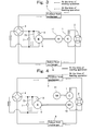
- Fig. 3 shows a structure of the heat pump type cooling and heating air conditioner of this embodiment.
- the heat pump type cooling and heating air conditioner of this embodiment uses a CO 2 refrigerant as refrigerant, and comprises a refrigerant circuit in which a compressor 1 having a motor 11, an outdoor heat exchanger 3, an expander 6 and an indoor heat exchanger 8 are connected to one another through pipes.
- the expander 6 is provided at its inflow side pipe with a pre-expansion valve 5.
- a bypass circuit which bypasses the pre-expansion valve 5 and the expander 6 is provided in parallel to the pre-expansion valve 5 and the expander 6.
- the bypass circuit is provided with a control valve 7.
- a drive shaft of the expander 6 and a drive shaft of the compressor 1 are connected to each other, and the compressor 1 utilizes power recover by the expander 6 for driving.
- the refrigerant circuit is provided with a first four-way valve 2 to which a discharge side pipe and a suction side pipe of the compressor 1 are connected, and a second four-way valve 4 to which a refrigerant-inflow side pipe of the pre-expansion valve 5, a refrigerant-outflow side pipe of the expander 6 and the bypass circuit are connected.
- the fluid supply pipe 73 introduces refrigerant which flows through a pipe extending from the second four-way valve 4 to the refrigerant-inflow port of the expander 6. It is preferable that the fluid supply pipe 73 is connected to the inflow side pipe of the pre-expansion valve 5.
- Refrigerant at the time of the cooling operation mode is compressed at a high temperature and under a high pressure and is discharged by the compressor 1 which is driven by the motor 11.
- the refrigerant is introduced into the outdoor heat exchanger 3 through the first four-way valve 2.
- the refrigerant is not brought into two-phase state, and dissipates heat to outside fluid such as air and water.
- the CO 2 refrigerant is introduced into the pre-expansion valve 5 and the expander 6 through the second four-way valve 4, and is expanded by the pre-expansion valve 5 and the expander 6. Power recover by the expander 6 at the time of expanding operation is used for driving the compressor 1.
- the opening'of the control valve 7 is adjusted in accordance with a high pressure detected at an outlet of the outdoor heat exchanger 3, thereby controlling an amount of refrigerant which is allowed to flow into the bypass circuit.
- the opening of the pre-expansion valve 5 is adjusted in accordance with the detected high pressure, thereby controlling an amount of refrigerant which is allowed to flow into the expander 6.
- the CO 2 refrigerant expanded by the pre-expansion valve 5 and the expander 6 is introduced into the indoor heat exchanger 8 through the second four-way valve 4 and is evaporated and suctions heat in the indoor heat exchanger 8. A room is cooled by this endotherm.
- the refrigerant which has been evaporated is drawn into compressor 1.
- Refrigerant at the time of the heating operation mode is compressed at a high temperature and under a high pressure and is discharged by the compressor 1 which is driven by the motor 11.
- the refrigerant is introduced into the indoor heat exchanger 8 through the first four-way valve 2.
- the indoor heat exchanger 8 since CO 2 refrigerant is in a supercritical state, the refrigerant is not brought into two-phase state, and dissipates heat to outside fluid such as air and water. A room is heated utilizing this radiation.
- the CO 2 refrigerant is introduced into the pre-expansion valve 5 and the expander 6, and is expanded by the pre-expansion valve 5 and the expander 6. Power recover by the expander 6 at the time of expanding operation is used for driving the compressor 1.
- the opening of the control valve 7 is adjusted in accordance with a high pressure detected at an outlet of the indoor heat exchanger 8, thereby controlling an amount of refrigerant which is allowed to flow into the bypass circuit.
- the opening of the pre-expansion valve 5 is adjusted in accordance with the detected high pressure, thereby controlling an amount of refrigerant which is allowed to flow into the expander 6.
- the CO 2 refrigerant expanded by the pre-expansion valve 5 and the expander 6 is introduced into the outdoor heat exchanger 3 through the second four-way valve 4 and is evaporated and suctions heat in the outdoor heat exchanger 3.
- the refrigerant which has been evaporated is drawn into the compressor 1 through the first four-way valve 2.
- High pressure refrigerant in the supercritical state is introduced into the back pressure chamber 68a in the expander 6 by the fluid supply pipe 73, and the high pressure refrigerant reliably pushes the vane 69 against the inner peripheral surface of the cylinder 61.
- the fluid supply pipe 73 introduces the refrigerant which flows through the pipe extending from the second four-way valve 4 to the refrigerant-inflow port of the expander 6, but the fluid supply pipe 73 may introduces refrigerant which flows through a pipe extending from a discharge port of the compressor 1 to the first four-way valve 2.
- a refrigeration cycle apparatus using an expander according to the embodiment of the present invention will be explained with reference to the drawing based on a heat pump type cooling and heating air conditioner of another embodiment.
- Fig. 4 shows a structure of the heat pump type cooling and heating air conditioner of this embodiment.
- the heat pump type cooling and heating air conditioner of this embodiment uses a CO 2 refrigerant as refrigerant, and comprises a refrigerant circuit in which a compressor 1 having a motor 11, an outdoor heat exchanger 3, an expander 6, an indoor heat exchanger 8 and an auxiliary compressor 10 are connected to one another through pipes.
- the expander 6 is provided at its inflow side pipe with a pre-expansion valve 5.
- a bypass circuit which bypasses the pre-expansion valve 5 and the expander 6 is provided in parallel to the pre-expansion valve 5 and the expander 6.
- the bypass circuit is provided with a control valve 7.
- a drive shaft of the expander 6 and a drive shaft of the auxiliary compressor 10 are connected to each other, and the auxiliary compressor 10 is driven by power recover by the expander 6.
- the refrigerant circuit is provided with a first four-way valve 2 to which a discharge side pipe of the compressor 1 and a suction side pipe of the auxiliary compressor 10 are connected, and a second four-way valve 4 to which a refrigerant-inflow side pipe of the pre-expansion valve 5, a refrigerant-outflow side pipe of the expander 6 and the bypass circuit are connected.
- the fluid supply pipe 73 introduces refrigerant which flows through a pipe extending from the second four-way valve 4 to the refrigerant-inflow port of the expander 6. It is preferable that the fluid supply pipe 73 is connected to the inflow side pipe of the pre-expansion valve 5.
- Refrigerant at the time of the cooling operation mode is compressed at a high temperature and under a high pressure and is discharged by the compressor 1 which is driven by the motor 11.
- the refrigerant is introduced into the outdoor heat exchanger 3 through the first four-way valve 2.
- the outdoor heat exchanger 3 since CO 2 refrigerant is in a supercritical state, the refrigerant is not brought into two-phase state, and dissipates heat to outside fluid such as air and water. Then, the CO 2 refrigerant is introduced into the pre-expansion valve 5 and the expander 6, and is expanded by the pre-expansion valve 5 and the expander 6. Power recover by the expander 6 at the time of expanding operation is used for driving the auxiliary compressor 10.
- the opening of the control valve 7 is adjusted in accordance with a high pressure detected at an outlet of the outdoor heat exchanger 3, thereby controlling an amount of refrigerant which is allowed to flow into the bypass valve.
- the opening of the pre-expansion valve 5 is adjusted in accordance with the detected high pressure, thereby controlling an amount of refrigerant which is allowed to flow into the expander 6.
- the CO 2 refrigerant expanded by the pre-expansion valve 5 and the expander 6 is introduced into the indoor heat exchanger 8 through the second four-way valve 4 and is evaporated and suctions heat in the indoor heat exchanger 8. A room is cooled by this endotherm.
- the refrigerant which has been evaporated is introduced into the auxiliary compressor 10 through the first four-way valve 2 and supercharged by the auxiliary compressor 10 and is drawn into compressor 1.
- Refrigerant at the time of the heating operation mode is compressed at a high temperature and under a high pressure and is discharged by the compressor 1 which is driven by the motor 11.
- the refrigerant is introduced into the indoor heat exchanger 8 through the first four-way valve 2.
- the indoor heat exchanger 8 since CO 2 refrigerant is in a supercritical state, the refrigerant is not brought into two-phase state, and dissipates heat to outside fluid such as air and water. A room is heated utilizing this radiation.
- the CO 2 refrigerant is introduced into the pre-expansion valve 5 and the expander 6, and is expanded by the pre-expansion valve 5 and the expander 6. Power recover by the expander 6 at the time of expanding operation is used for driving the auxiliary compressor 10.
- the opening of the control valve 7 is adjusted in accordance with a high pressure detected at an outlet of the indoor heat exchanger 8, thereby controlling an amount of refrigerant which is allowed to flow into the bypass valve.
- the opening of the pre-expansion valve 5 is adjusted in accordance with the detected high pressure, thereby controlling an amount of refrigerant which is allowed to flow into the expander 6.
- the CO 2 refrigerant expanded by the pre-expansion valve 5 and the expander 6 is introduced into the outdoor heat exchanger 3 through the second four-way valve 4 and is evaporated and suctions heat in the outdoor heat exchanger 3.
- the refrigerant which has been evaporated is introduced into the auxiliary compressor 10 through the first four-way valve 2 and supercharged by the auxiliary compressor 10 and drawn into the compressor 1.
- High pressure refrigerant in the supercritical state is introduced into the back pressure chamber 68a in the expander 6 by the fluid supply pipe 73, and the high pressure refrigerant reliably pushes the vane 69 against the inner peripheral surface of the cylinder 61.
- the fluid supply pipe 73 introduces the refrigerant which flows through the pipe extending from the second four-way valve 4 to the refrigerant-inflow port of the expander 6, but the fluid supply pipe 73 may introduces refrigerant which flows through a pipe extending from a discharge port of the compressor 1 to the first four-way valve 2.
- a refrigeration cycle apparatus using an expander according to the embodiment of the present invention will be explained with reference to the drawing based on a heat pump type cooling and heating air conditioner of another embodiment.
- Fig. 5 shows a structure of the heat pump type cooling and heating air conditioner of this embodiment.
- the heat pump type cooling and heating air conditioner of this embodiment uses a CO 2 refrigerant as refrigerant, and comprises a refrigerant circuit in which a compressor 1 having a motor 11, an auxiliary compressor 10, an outdoor heat exchanger 3, an expander 6 and an indoor heat exchanger 8 are connected to one another through pipes.
- the expander 6 is provided at its inflow side pipe with a pre-expansion valve 5.
- a bypass circuit which bypasses the pre-expansion valve 5 and the expander 6 is provided in parallel to the pre-expansion valve 5 and the expander 6.
- the bypass circuit is provided with a control valve 7.
- a drive shaft of the expander 6 and a drive shaft of the auxiliary compressor 10 are connected to each other, and the auxiliary compressor 10 is driven by power recover by the expander 6.
- the refrigerant circuit is provided with a first four-way valve 2 to which a suction side pipe of the compressor 1 and a discharge side pipe of the auxiliary compressor 10 are connected, and a second four-way valve 4 to which a suction side pipe of the pre-expansion valve 5, a discharge side pipe of the expander 6 and the bypass circuit are connected.
- the fluid supply pipe 73 introduces refrigerant which flows through a pipe extending from the second four-way valve 4 to the refrigerant-inflow port of the expander 6. It is preferable that the fluid supply pipe 73 is connected to the inflow side pipe of the pre-expansion valve 5.
- Refrigerant at the time of the cooling operation mode is compressed at a high temperature and under a high pressure and is discharged by the compressor 1 which is driven by the motor 11.
- the refrigerant is introduced into the auxiliary compressor 10 and super -pressurized by the auxiliary compressor 10 and then, is introduced into the outdoor heat exchanger 3 through the first four-way valve 2.
- the outdoor heat exchanger 3 since CO 2 refrigerant is in a supercritical state, the refrigerant is not brought into two-phase state, and dissipates heat to outside fluid such as air and water. Then, the CO 2 refrigerant is introduced into the pre-expansion valve 5 and the expander 6, and is expanded by the pre-expansion valve 5 and the expander 6.
- Power recover by the expander 6 at the time of expanding operation is used for driving the auxiliary compressor 10.
- the opening of the control valve 7 is adjusted in accordance with a high pressure detected at an outlet of the outdoor heat exchanger 3, thereby controlling an amount of refrigerant which is allowed to flow into the bypass valve.
- the opening of the pre-expansion valve 5 is adjusted in accordance with the detected high pressure, thereby controlling an amount of refrigerant which is allowed to flow into the expander 6.
- the CO 2 refrigerant expanded by the pre-expansion valve 5 and the expander 6 is introduced into the indoor heat exchanger 8 through the second four-way valve 4 and is evaporated and suctions heat in the indoor heat exchanger 8. A room is cooled by this endotherm.
- the refrigerant which has been evaporated is drawn into compressor 1 through the first four-way valve 2.
- Refrigerant at the time of the heating operation mode is compressed at a high temperature and under a high pressure and is discharged by the compressor 1 which is driven by the motor 11.
- the refrigerant is introduced into the auxiliary compressor 10 and super-pressurized by the auxiliary compressor 10 and then, is introduced into the indoor heat exchanger 8 through the first four-way valve 2.
- the indoor heat exchanger 8 since CO 2 refrigerant is in a supercritical state, the refrigerant is not brought into two-phase state, and dissipates heat to outside fluid such as air and water. A room is heated utilizing this radiation. Then, the CO 2 refrigerant is introduced into the pre-expansion valve 5 and the expander 6, and is expanded by the pre-expansion valve 5 and the expander 6.
- Power recover by the expander 6 at the time of expanding operation is used for driving the auxiliary compressor 10.
- the opening of the control valve 7 is adjusted in accordance with a high pressure detected at an outlet of the indoor heat exchanger 8, thereby controlling an amount of refrigerant which is allowed to flow into the bypass circuit.
- the opening of the pre-expansion valve 5 is adjusted in accordance with the detected high pressure, thereby controlling an amount of refrigerant which is allowed to flow into the expander 6.
- the CO 2 refrigerant expanded by the pre-expansion valve 5 and the expander 6 is introduced into the outdoor heat exchanger 3 through the second four-way valve 4 and is evaporated and suctions heat in the outdoor heat exchanger 3.
- the refrigerant which has been evaporated is drawn into the compressor 1 through the first four-way valve 2.
- High pressure refrigerant in the supercritical state is introduced into the back pressure chamber 68a in the expander 6 by the fluid supply pipe 73, and the high pressure refrigerant reliably pushes the vane 69 against the inner peripheral surface of the cylinder 61.
- the fluid supply pipe 73 introduces the refrigerant which flows through the pipe extending from the second four-way valve 4 to the refrigerant-inflow port of the expander 6, but the fluid supply pipe 73 may introduces refrigerant which flows through a pipe extending from a discharge port of the compressor 1 to the first four-way valve 2.
- a refrigeration cycle apparatus using an expander according to the embodiment of the present invention will be explained with reference to the drawing based on a heat pump type cooling and heating air conditioner of another embodiment.
- Fig. 6 shows a structure of the heat pump type cooling and heating air conditioner of this embodiment.
- the heat pump type cooling and heating air conditioner of this embodiment uses a CO 2 refrigerant as refrigerant, and comprises a refrigerant circuit in which a compressor 1 having a motor 11, an outdoor heat exchanger 3, an expander 6, an indoor heat exchanger 8 and an auxiliary compressor 10 are connected to one another through pipes.
- the refrigerant circuit comprises a first four-way valve 2 to which a discharge side pipe and a suction side pipe of the compressor 1 are connected, a second four-way valve 4 to which a discharge side pipe and a suction side pipe of the expander 6 are connected, and a third four-way valve 9 to which a discharge side pipe and a suction side pipe of the auxiliary compressor 10 are connected.
- the first four-way valve 2 and the third four-way valve 9 are switched over so that the discharge side of the auxiliary compressor 10 becomes the suction side of the compressor 1.
- the first four-way valve 2 and the third four-way valve 9 are switched over so that the discharge side of the compressor 1 becomes the suction side of the auxiliary compressor 10.
- the second four-way valve 4 By switching the second four-way valve 4, a direction of the refrigerant flowing through the expander 6 becomes always the same direction.
- the expander 6 is provided at its inflow side with a pre-expansion valve 5 capable of changing the opening of the valve.
- a bypass circuit which bypasses the pre-expansion valve 5 and the expander 6 is provided.
- the bypass circuit is provided with a bypass valve 7 which adjusts a flow rate of refrigerant of the bypass circuit.
- a drive shaft of the expander 6 and a drive shaft of the auxiliary compressor 10 are connected to each other, and the auxiliary compressor 10 is driven by power recover by the expander 6.
- the fluid supply pipe 73 introduces refrigerant which flows through a pipe extending from the second four-way valve 4 to the refrigerant-inflow port of the expander 6. It is preferable that the fluid supply pipe 73 is connected to the inflow side pipe of the pre-expansion valve 5.
- Refrigerant at the time of the cooling operation mode is compressed at a high temperature and under a high pressure and is discharged by the compressor 1 which is driven by the motor 11.
- the refrigerant is introduced into the outdoor heat exchanger 3 through the first four-way valve 2.
- the refrigerant is not brought into two-phase state, and dissipates heat to outside fluid such as air and water.
- the CO 2 refrigerant is introduced into the second four-way valve 4, the pre-expansion valve 5 and the expander 6, and is expanded by the expander 6.
- an optimal amount of refrigerant flowing into the expander 6 is calculated from a high pressure refrigerant temperature and a high pressure refrigerant pressure detected on the side of the outlet of the outdoor heat exchanger 3.
- the opening of the pre-expansion valve 5 or the bypass valve 7 is adjusted such that if the volume flow rate is greater than the calculated optimal refrigerant amount, the opening of the bypass valve 7 is increased to reduce the volume flow rate of refrigerant flowing into the expander 6, and if the volume flow rate is smaller than the calculated optimal refrigerant amount, the opening of the pre-expansion valve 5 is reduced to increase the volume flow rate.
- the expanded CO 2 refrigerant is evaporated and suctions heat in the indoor heat exchanger 8 through the second four-way valve 4.
- a room is cooled by this endotherm.
- the refrigerant which has been evaporated is introduced into the auxiliary compressor 10 through the third four-way valve 9 and supercharged by the auxiliary compressor 10, and is drawn into the compressor 1 through the third four-way valve 9 and the first four-way valve 2. Energy generated when expansion is carried out in the expander 6 is utilized for this supercharging operation of the auxiliary compressor 10, and power is recovered.
- Refrigerant at the time of the heating operation mode is compressed at a high temperature and under a high pressure and is discharged by the compressor 1 which is driven by the motor 11.
- the refrigerant is introduced into the auxiliary compressor 10 through the first four-way valve 2 and the third four-way valve 9, and further super-pressurized by the auxiliary compressor 10.
- the expansion energy at the expander 6 is utilized for this super-pressurizing operation and power is recovered.
- the super-pressurized refrigerant is introduced into the indoor heat exchanger 8 through the third four-way valve 9. In the indoor heat exchanger 8, since CO 2 refrigerant is in a supercritical state, the refrigerant is not brought into two-phase state, and dissipates heat to outside fluid such as air and water.
- the CO 2 refrigerant is introduced into the expander 6 through the second four-way valve 4 and the pre-expansion valve 5, and is expanded by the expander 6.
- an optimal amount of refrigerant flowing into the expander 6 is calculated from a high pressure refrigerant temperature and a high pressure refrigerant pressure detected on the side of the outlet of the indoor heat exchanger 8.
- the opening of the pre-expansion valve 5 or the bypass valve 7 is adjusted such that if the volume flow rate is greater than the calculated optimal refrigerant amount, the opening of the bypass valve 7 is increased to reduce the volume flow rate of refrigerant flowing into the expander 6, and if the volume flow rate is smaller than the calculated optimal refrigerant amount, the opening of the pre-expansion valve 5 is reduced to increase the volume flow rate.
- the expanded CO 2 refrigerant is evaporated and suctions heat in the outdoor heat exchanger 3 through the second four-way valve 4.
- the refrigerant which has been evaporated is drawn into the compressor 1 through the first four-way valve 2.
- High pressure refrigerant in the supercritical state is introduced into the back pressure chamber 68a in the expander 6 by the fluid supply pipe 73, and the high pressure refrigerant reliably pushes the vane 69 against the inner peripheral surface of the cylinder 61.
- the fluid supply pipe 73 introduces the refrigerant which flows through the pipe extending from the second four-way valve 4 to the refrigerant-inflow port of the expander 6, but the fluid supply pipe 73 may introduces refrigerant which flows through a pipe extending from a discharge port of the compressor 1 to the first four-way valve 2.
- the compressor 1 which compresses refrigerant and the expander 6 and the auxiliary compressor 10 which recover the power are separated from each other.
- the refrigeration cycle is switched such that the refrigerant is supercharged by the auxiliary compressor 10 at the time of the cooling operation mode, and the refrigerant is super-pressurized at the time of the heating operation mode.
- a sliding vane type expander is used as the expander 6, no oil reservoir is provided in a hausing 60, and lubrication in the expander 6 is carried out using oil mist discharged from the compressor 1. Therefore, it is possible to avoid a problem that oil level in each of a plurality of oil reservoirs must be controlled.
- the auxiliary compressor 10 and the expander 6 are connected to each other and the auxiliary compressor 10 supercharges and super-pressurizes as in the embodiment shown in Fig. 6, since the expander 6 does not have the oil reservoir, it is possible to integrally form the auxiliary compressor 10 and the expander 6.
- the present invention can also be applied to other refrigeration cycle apparatuses in which the outdoor heat exchanger 3 is used as a first heat exchanger, the indoor heat exchanger 8 is used as a second heat exchanger, and the first and second heat exchangers are utilized for hot and cool water devices or thermal storages.
- the drive shaft of the expander 6 is connected to the drive shaft of the compressor 1 or the auxiliary compressor 10, and power recover by the expander 6 is utilized for driving the compressor 1 or the auxiliary compressor 10, but the drive shaft of the expander 6 may be provided with an electric generator to convert the power into electricity.
- the compressor 1 and the auxiliary compressor 10 explained in the above embodiments can be formed into a sliding vane type compressor explained in Fig. 1 and Fig. 2.
- the expansion space is formed into a compression space.
- the expander 6 and the auxiliary compressor 10 can be lubricated only with oil mist discharged from the compressor 1, and the expander 6 and the auxiliary compressor 10 do not require a hausing having an oil reservoir.
- the present invention by introducing the refrigerant in the supercritical state, since the refrigerant is not in the gas state, it is possible to reduce the leakage of refrigerant from a gap between a vane groove and a vane.
- a portion of refrigerant flowing through the suction pipe is introduced into the back pressure chamber, and since it is unnecessary to separately introduce refrigerant from outside of the expander, the mechanism can be simplified.
Landscapes
- Engineering & Computer Science (AREA)
- Mechanical Engineering (AREA)
- General Engineering & Computer Science (AREA)
- Physics & Mathematics (AREA)
- Thermal Sciences (AREA)
- Chemical & Material Sciences (AREA)
- Combustion & Propulsion (AREA)
- Chemical Kinetics & Catalysis (AREA)
- Applications Or Details Of Rotary Compressors (AREA)
- Rotary Pumps (AREA)
- Compression-Type Refrigeration Machines With Reversible Cycles (AREA)
Abstract
Description
Claims (8)
- An expander used in a refrigeration cycle using carbon dioxide as refrigerant and having a compressor, an outdoor heat exchanger and an indoor heat exchanger, wherein said expander comprises a cylindrical cylinder, a rotor which rotates in said cylinder, a vane which divides an expansion space formed between an inner peripheral surface of said cylinder and an outer peripheral surface of said rotor into a plurality of spaces, and a vane groove provided in said rotor for accommodating said vane therein, and wherein said vane groove is provided with a back pressure chamber which pushes said vane against the inner peripheral surface of said cylinder, and said refrigerant in the supercritical state is introduced into said back pressure chamber.
- An expander according to claim 1, further comprising a suction pipe which introduces refrigerant into said expansion space, wherein a portion of refrigerant flowing through said suction pipe is introduced into said back pressure chamber.
- An expander according to claim 1, wherein no oil reservoir is provided in a hausing which includes said cylinder or said rotor therein.
- A refrigeration cycle apparatus having a refrigeration cycle using carbon dioxide as refrigerant and having a compressor, an outdoor heat exchanger, an expander and an indoor heat exchanger, said refrigeration cycle apparatus including, in said refrigeration cycle, a first four-way valve to which a discharge side pipe and a suction side pipe of said compressor are connected, and a second four-way valve to which a refrigerant-inflow side pipe and a refrigerant-outflow side pipe of said expander are connected, wherein using, as said expander, a sliding vane type expander having a cylindrical cylinder, a rotor which rotates in said cylinder, a vane which divides an expansion space formed between an inner peripheral surface of said cylinder and an outer peripheral surface of said rotor into a plurality of spaces, and a vane groove provided in said rotor for accommodating said vane therein, refrigerant flowing through a pipe extending from said second four-way valve to a refrigerant-inflow port of said expander is introduced into a back surface of said vane.
- A refrigeration cycle apparatus having a refrigeration cycle using carbon dioxide as refrigerant and having a compressor, an outdoor heat exchanger, an expander and an indoor heat exchanger, said refrigeration cycle apparatus including, in said refrigeration cycle, a first four-way valve to which a discharge side pipe and a suction side pipe of said compressor are connected, and a second four-way valve to which a refrigerant-inflow side pipe and a refrigerant-outflow side pipe of said expander are connected, wherein using, as said expander, a sliding vane type expander having a cylindrical cylinder, a rotor which rotates in said cylinder, a vane which divides an expansion space formed between an inner peripheral surface of said cylinder and an outer peripheral surface of said rotor into a plurality of spaces, and a vane groove provided in said rotor for accommodating said vane therein, refrigerant flowing through a pipe extending from a discharge port of said compressor to said first four-way valve is introduced into a back surface of said vane.
- A refrigeration cycle apparatus according to claim 4 or 5, wherein said expander is lubricated by oil mist discharged from said compressor.
- A compressor used in a refrigeration cycle using carbon dioxide as refrigerant and having an outdoor heat exchanger and an indoor heat exchanger, wherein said compressor comprises a cylindrical cylinder, a rotor which rotates in said cylinder, a vane which divides a compression space formed between an inner peripheral surface of said cylinder and an outer peripheral surface of said rotor into a plurality of spaces, and a vane groove provided in said rotor for accommodating said vane therein, and wherein said vane groove is provided with a back pressure chamber which pushes said vane against the inner peripheral surface of said cylinder, and said refrigerant in the supercritical state is introduced into said back pressure chamber.
- A compressor according to claim 7, further comprising a discharge pipe which discharges refrigerant from said compression space, wherein a portion of refrigerant flowing through said discharge pipe is introduced into said back pressure chamber.
Applications Claiming Priority (2)
| Application Number | Priority Date | Filing Date | Title |
|---|---|---|---|
| JP2002303982A JP2004137979A (en) | 2002-10-18 | 2002-10-18 | Expansion machine |
| JP2002303982 | 2002-10-18 |
Publications (2)
| Publication Number | Publication Date |
|---|---|
| EP1411309A2 true EP1411309A2 (en) | 2004-04-21 |
| EP1411309A3 EP1411309A3 (en) | 2004-04-28 |
Family
ID=32040854
Family Applications (1)
| Application Number | Title | Priority Date | Filing Date |
|---|---|---|---|
| EP03019374A Withdrawn EP1411309A3 (en) | 2002-10-18 | 2003-08-27 | Expander |
Country Status (3)
| Country | Link |
|---|---|
| US (1) | US6877340B2 (en) |
| EP (1) | EP1411309A3 (en) |
| JP (1) | JP2004137979A (en) |
Cited By (3)
| Publication number | Priority date | Publication date | Assignee | Title |
|---|---|---|---|---|
| WO2010072766A3 (en) * | 2008-12-23 | 2011-03-24 | Reinhard Liehs | Apparatus for obtaining electric current |
| EP2142860A4 (en) * | 2007-03-16 | 2012-06-06 | Carrier Corp | Refrigerant system with variable capacity expander |
| EP2476973A4 (en) * | 2009-10-07 | 2017-08-16 | Mitsubishi Electric Corporation | Refrigeration cycle device |
Families Citing this family (16)
| Publication number | Priority date | Publication date | Assignee | Title |
|---|---|---|---|---|
| US7841205B2 (en) * | 2005-08-15 | 2010-11-30 | Whitemoss, Inc. | Integrated compressor/expansion engine |
| JP4537948B2 (en) * | 2005-12-22 | 2010-09-08 | ヤンマー株式会社 | Scroll type expander and Rankine cycle power generation system |
| JP2007224853A (en) * | 2006-02-24 | 2007-09-06 | Matsushita Electric Ind Co Ltd | Refrigeration cycle apparatus and expander |
| WO2007121540A2 (en) * | 2006-04-20 | 2007-11-01 | Springer Carrier Ltda | Heat pump system having auxiliary water heating and heat exchanger bypass |
| GB0609326D0 (en) * | 2006-05-02 | 2006-06-21 | Bayram Peter J | Power generating & cooling refrigeration expansion 'valve' |
| US7607314B2 (en) * | 2006-12-15 | 2009-10-27 | Nissan Technical Center North America, Inc. | Air conditioning system |
| JP5103952B2 (en) * | 2007-03-08 | 2012-12-19 | ダイキン工業株式会社 | Refrigeration equipment |
| US8327651B2 (en) * | 2009-07-07 | 2012-12-11 | Hamilton Sundstrand Corporation | Transcritical fluid cooling for aerospace applications |
| US8459048B2 (en) | 2010-07-23 | 2013-06-11 | Nissan North America, Inc. | Gerotor expander for an air conditioning system |
| WO2012049259A1 (en) | 2010-10-14 | 2012-04-19 | Energreen Heat Recovery As | Method and system for the utilization of an energy source of relatively low temperature |
| WO2012162126A2 (en) * | 2011-05-20 | 2012-11-29 | Cathriner Richard John | Air conditioning system with discharged heat driving compression of system refrigerant |
| JP5641004B2 (en) * | 2012-03-16 | 2014-12-17 | 三菱電機株式会社 | Refrigeration cycle equipment |
| JP5305210B1 (en) * | 2012-10-17 | 2013-10-02 | 武史 畑中 | ELECTRO-HYDRAULIC ENGINE, VEHICLE HAVING THE SAME, PLUG-IN HYBRID VEHICLE AND ELECTRO-HYDRAULIC ENERGY CONVERTING |
| US20170350650A1 (en) * | 2016-06-02 | 2017-12-07 | General Electric Company | System and method of recovering carbon dioxide from an exhaust gas stream |
| US10844744B2 (en) | 2017-09-01 | 2020-11-24 | Southwest Research Institute | Double wall supercritical carbon dioxide turboexpander |
| CN116678105A (en) * | 2022-02-22 | 2023-09-01 | 海德韦尔(太仓)能源科技有限公司 | An energy recovery device and an air conditioner including the energy recovery device |
Citations (1)
| Publication number | Priority date | Publication date | Assignee | Title |
|---|---|---|---|---|
| JP2001141315A (en) | 1999-11-10 | 2001-05-25 | Aisin Seiki Co Ltd | Refrigeration air conditioner |
Family Cites Families (21)
| Publication number | Priority date | Publication date | Assignee | Title |
|---|---|---|---|---|
| US327745A (en) * | 1885-10-06 | Fastening for railroad-rails | ||
| US1539728A (en) * | 1924-02-23 | 1925-05-26 | Lloyd V Reynolds | Rotary pump |
| DE1503590A1 (en) * | 1965-02-25 | 1969-07-03 | Paming Trust Reg | Rotary piston machine as an air compressor |
| DE2261873A1 (en) * | 1972-12-18 | 1974-06-27 | Langen & Co | VANE CELL MOTOR |
| IL48176A (en) * | 1974-12-24 | 1977-12-30 | Gen Electric | Low leakage rotary multivaned expander |
| US4174931A (en) * | 1976-12-17 | 1979-11-20 | Diesel Kiki Company, Ltd. | Vane for rotary compressor |
| US4248575A (en) * | 1979-01-29 | 1981-02-03 | Robert Bosch Gmbh | Rotary fluid pressure biased vane compressor with pressure release means |
| JPS5690489U (en) * | 1979-12-14 | 1981-07-18 | ||
| JPS57108555A (en) * | 1980-12-25 | 1982-07-06 | Mitsubishi Electric Corp | Air/liquid converter |
| US4455129A (en) * | 1981-05-19 | 1984-06-19 | Daikin Kogyo Co., Ltd. | Multi-vane type compressor |
| JPS59185887A (en) * | 1983-04-06 | 1984-10-22 | Diesel Kiki Co Ltd | Vane type compressor |
| JPS6277562A (en) * | 1985-09-30 | 1987-04-09 | 株式会社東芝 | Refrigeration cycle |
| US5327745A (en) * | 1993-09-28 | 1994-07-12 | The United States Of America As Represented By The Secretary Of The Navy | Malone-Brayton cycle engine/heat pump |
| JPH1019401A (en) * | 1996-07-01 | 1998-01-23 | Sanden Corp | Refrigerating air conditioner |
| CA2295560A1 (en) * | 1997-07-11 | 1999-01-21 | Bruce E. Mcclellan | High efficiency rotary vane motor |
| FR2779215B1 (en) * | 1998-05-28 | 2000-08-04 | Valeo Climatisation | AIR CONDITIONING CIRCUIT USING A SUPERCRITICAL REFRIGERANT FLUID, PARTICULARLY FOR VEHICLE |
| US6321564B1 (en) * | 1999-03-15 | 2001-11-27 | Denso Corporation | Refrigerant cycle system with expansion energy recovery |
| JP4273588B2 (en) * | 1999-08-30 | 2009-06-03 | ダイキン工業株式会社 | Air conditioner refrigerant circuit |
| JP2001108257A (en) * | 1999-10-05 | 2001-04-20 | Daikin Ind Ltd | Separate type air conditioner using carbon dioxide refrigerant and installation method thereof |
| JP2001207983A (en) * | 2000-01-26 | 2001-08-03 | Seiko Seiki Co Ltd | Gas compressor |
| NO20005576D0 (en) * | 2000-09-01 | 2000-11-03 | Sinvent As | Reversible evaporation process |
-
2002
- 2002-10-18 JP JP2002303982A patent/JP2004137979A/en active Pending
-
2003
- 2003-08-27 EP EP03019374A patent/EP1411309A3/en not_active Withdrawn
- 2003-09-09 US US10/657,182 patent/US6877340B2/en not_active Expired - Fee Related
Patent Citations (1)
| Publication number | Priority date | Publication date | Assignee | Title |
|---|---|---|---|---|
| JP2001141315A (en) | 1999-11-10 | 2001-05-25 | Aisin Seiki Co Ltd | Refrigeration air conditioner |
Cited By (3)
| Publication number | Priority date | Publication date | Assignee | Title |
|---|---|---|---|---|
| EP2142860A4 (en) * | 2007-03-16 | 2012-06-06 | Carrier Corp | Refrigerant system with variable capacity expander |
| WO2010072766A3 (en) * | 2008-12-23 | 2011-03-24 | Reinhard Liehs | Apparatus for obtaining electric current |
| EP2476973A4 (en) * | 2009-10-07 | 2017-08-16 | Mitsubishi Electric Corporation | Refrigeration cycle device |
Also Published As
| Publication number | Publication date |
|---|---|
| US6877340B2 (en) | 2005-04-12 |
| JP2004137979A (en) | 2004-05-13 |
| EP1411309A3 (en) | 2004-04-28 |
| US20040074256A1 (en) | 2004-04-22 |
Similar Documents
| Publication | Publication Date | Title |
|---|---|---|
| US6877340B2 (en) | Expander | |
| JP5178560B2 (en) | Refrigeration cycle equipment | |
| EP1416232B1 (en) | Refrigerating apparatus | |
| US9086230B2 (en) | Refrigeration cycle device | |
| US6880357B2 (en) | Refrigeration cycle apparatus | |
| CN102510985B (en) | Refrigeration cycle device | |
| EP2123996B1 (en) | Refrigerating device | |
| US20040074254A1 (en) | Refrigeration cycle apparatus | |
| EP1215450A1 (en) | Multi-stage compression refrigerating device | |
| CN102822609A (en) | Refrigeration cycle apparatus and method for operating same | |
| JP4815286B2 (en) | Two-way refrigeration cycle equipment | |
| WO2009098899A1 (en) | Refrigeration system | |
| JP4079114B2 (en) | Fluid machinery | |
| JP2004301453A (en) | Partially closed type multistage compressor | |
| JP2008170118A (en) | Heat pump type equipment | |
| US20100074769A1 (en) | Fluid machine | |
| JP2001207983A (en) | Gas compressor | |
| JP2013019336A (en) | Expander and refrigerating device | |
| JP5115355B2 (en) | Fluid machinery | |
| KR20060122038A (en) | High Efficiency Air Cycle System | |
| JP2008223651A (en) | Fluid machinery | |
| JP2006214610A (en) | Refrigeration equipment | |
| JP2004301075A (en) | Semi-hermetic multistage compressor | |
| JP2003130479A (en) | Refrigeration equipment | |
| JP2013108713A (en) | Refrigeration device |
Legal Events
| Date | Code | Title | Description |
|---|---|---|---|
| PUAI | Public reference made under article 153(3) epc to a published international application that has entered the european phase |
Free format text: ORIGINAL CODE: 0009012 |
|
| PUAL | Search report despatched |
Free format text: ORIGINAL CODE: 0009013 |
|
| AK | Designated contracting states |
Kind code of ref document: A2 Designated state(s): AT BE BG CH CY CZ DE DK EE ES FI FR GB GR HU IE IT LI LU MC NL PT RO SE SI SK TR |
|
| AX | Request for extension of the european patent |
Extension state: AL LT LV MK |
|
| AK | Designated contracting states |
Kind code of ref document: A3 Designated state(s): AT BE BG CH CY CZ DE DK EE ES FI FR GB GR HU IE IT LI LU MC NL PT RO SE SI SK TR |
|
| AX | Request for extension of the european patent |
Extension state: AL LT LV MK |
|
| 17P | Request for examination filed |
Effective date: 20040604 |
|
| AKX | Designation fees paid |
Designated state(s): DE ES FR IT |
|
| 17Q | First examination report despatched |
Effective date: 20070716 |
|
| STAA | Information on the status of an ep patent application or granted ep patent |
Free format text: STATUS: THE APPLICATION IS DEEMED TO BE WITHDRAWN |
|
| 18D | Application deemed to be withdrawn |
Effective date: 20071127 |