EP1411215A1 - Engine oil cooling - Google Patents
Engine oil cooling Download PDFInfo
- Publication number
- EP1411215A1 EP1411215A1 EP20030256433 EP03256433A EP1411215A1 EP 1411215 A1 EP1411215 A1 EP 1411215A1 EP 20030256433 EP20030256433 EP 20030256433 EP 03256433 A EP03256433 A EP 03256433A EP 1411215 A1 EP1411215 A1 EP 1411215A1
- Authority
- EP
- European Patent Office
- Prior art keywords
- coolant
- temperature
- oil
- engine
- flow
- Prior art date
- Legal status (The legal status is an assumption and is not a legal conclusion. Google has not performed a legal analysis and makes no representation as to the accuracy of the status listed.)
- Granted
Links
- 238000001816 cooling Methods 0.000 title claims abstract description 32
- 239000010705 motor oil Substances 0.000 title claims abstract description 11
- 239000002826 coolant Substances 0.000 claims abstract description 108
- 239000003921 oil Substances 0.000 claims abstract description 104
- 238000002485 combustion reaction Methods 0.000 claims abstract description 10
- 238000010438 heat treatment Methods 0.000 claims abstract description 9
- 238000000034 method Methods 0.000 claims description 14
- 238000005461 lubrication Methods 0.000 claims description 9
- 239000007788 liquid Substances 0.000 claims description 4
- 239000002184 metal Substances 0.000 claims description 4
- 238000010792 warming Methods 0.000 claims description 2
- 239000000446 fuel Substances 0.000 description 7
- 230000001276 controlling effect Effects 0.000 description 3
- XLYOFNOQVPJJNP-UHFFFAOYSA-N water Substances O XLYOFNOQVPJJNP-UHFFFAOYSA-N 0.000 description 3
- LYCAIKOWRPUZTN-UHFFFAOYSA-N Ethylene glycol Chemical compound OCCO LYCAIKOWRPUZTN-UHFFFAOYSA-N 0.000 description 2
- 238000011217 control strategy Methods 0.000 description 2
- 239000011159 matrix material Substances 0.000 description 2
- 230000015572 biosynthetic process Effects 0.000 description 1
- 230000015556 catabolic process Effects 0.000 description 1
- 239000003054 catalyst Substances 0.000 description 1
- 230000003197 catalytic effect Effects 0.000 description 1
- 238000006731 degradation reaction Methods 0.000 description 1
- 230000000694 effects Effects 0.000 description 1
- 239000000839 emulsion Substances 0.000 description 1
- 239000007789 gas Substances 0.000 description 1
- WGCNASOHLSPBMP-UHFFFAOYSA-N hydroxyacetaldehyde Natural products OCC=O WGCNASOHLSPBMP-UHFFFAOYSA-N 0.000 description 1
- 239000000203 mixture Substances 0.000 description 1
- 230000001105 regulatory effect Effects 0.000 description 1
Images

Classifications
-
- F—MECHANICAL ENGINEERING; LIGHTING; HEATING; WEAPONS; BLASTING
- F01—MACHINES OR ENGINES IN GENERAL; ENGINE PLANTS IN GENERAL; STEAM ENGINES
- F01M—LUBRICATING OF MACHINES OR ENGINES IN GENERAL; LUBRICATING INTERNAL COMBUSTION ENGINES; CRANKCASE VENTILATING
- F01M5/00—Heating, cooling, or controlling temperature of lubricant; Lubrication means facilitating engine starting
-
- F—MECHANICAL ENGINEERING; LIGHTING; HEATING; WEAPONS; BLASTING
- F01—MACHINES OR ENGINES IN GENERAL; ENGINE PLANTS IN GENERAL; STEAM ENGINES
- F01M—LUBRICATING OF MACHINES OR ENGINES IN GENERAL; LUBRICATING INTERNAL COMBUSTION ENGINES; CRANKCASE VENTILATING
- F01M5/00—Heating, cooling, or controlling temperature of lubricant; Lubrication means facilitating engine starting
- F01M5/005—Controlling temperature of lubricant
-
- F—MECHANICAL ENGINEERING; LIGHTING; HEATING; WEAPONS; BLASTING
- F01—MACHINES OR ENGINES IN GENERAL; ENGINE PLANTS IN GENERAL; STEAM ENGINES
- F01P—COOLING OF MACHINES OR ENGINES IN GENERAL; COOLING OF INTERNAL-COMBUSTION ENGINES
- F01P7/00—Controlling of coolant flow
- F01P7/14—Controlling of coolant flow the coolant being liquid
- F01P7/16—Controlling of coolant flow the coolant being liquid by thermostatic control
- F01P7/165—Controlling of coolant flow the coolant being liquid by thermostatic control characterised by systems with two or more loops
-
- F—MECHANICAL ENGINEERING; LIGHTING; HEATING; WEAPONS; BLASTING
- F01—MACHINES OR ENGINES IN GENERAL; ENGINE PLANTS IN GENERAL; STEAM ENGINES
- F01P—COOLING OF MACHINES OR ENGINES IN GENERAL; COOLING OF INTERNAL-COMBUSTION ENGINES
- F01P2025/00—Measuring
- F01P2025/08—Temperature
-
- F—MECHANICAL ENGINEERING; LIGHTING; HEATING; WEAPONS; BLASTING
- F01—MACHINES OR ENGINES IN GENERAL; ENGINE PLANTS IN GENERAL; STEAM ENGINES
- F01P—COOLING OF MACHINES OR ENGINES IN GENERAL; COOLING OF INTERNAL-COMBUSTION ENGINES
- F01P2025/00—Measuring
- F01P2025/08—Temperature
- F01P2025/33—Cylinder head temperature
-
- F—MECHANICAL ENGINEERING; LIGHTING; HEATING; WEAPONS; BLASTING
- F01—MACHINES OR ENGINES IN GENERAL; ENGINE PLANTS IN GENERAL; STEAM ENGINES
- F01P—COOLING OF MACHINES OR ENGINES IN GENERAL; COOLING OF INTERNAL-COMBUSTION ENGINES
- F01P2025/00—Measuring
- F01P2025/08—Temperature
- F01P2025/40—Oil temperature
-
- F—MECHANICAL ENGINEERING; LIGHTING; HEATING; WEAPONS; BLASTING
- F01—MACHINES OR ENGINES IN GENERAL; ENGINE PLANTS IN GENERAL; STEAM ENGINES
- F01P—COOLING OF MACHINES OR ENGINES IN GENERAL; COOLING OF INTERNAL-COMBUSTION ENGINES
- F01P2037/00—Controlling
- F01P2037/02—Controlling starting
-
- F—MECHANICAL ENGINEERING; LIGHTING; HEATING; WEAPONS; BLASTING
- F01—MACHINES OR ENGINES IN GENERAL; ENGINE PLANTS IN GENERAL; STEAM ENGINES
- F01P—COOLING OF MACHINES OR ENGINES IN GENERAL; COOLING OF INTERNAL-COMBUSTION ENGINES
- F01P2060/00—Cooling circuits using auxiliaries
- F01P2060/04—Lubricant cooler
Definitions
- This invention relates to a method and system for cooling of lubrication oil in internal combustion engines and in particular to the cooling or heating of Diesel engine lubrication systems of motor vehicles.
- Modern Diesel engines for light commercial vehicles and passenger cars are typically provided with turbochargers, and may also be provided with intercoolers.
- the heat produced by these engines is such that the lubrication oil needs to be cooled to prevent degradation and consequent engine wear, and the oil is therefore passed through a heat exchanger which may in turn be cooled by air flow or by the engine coolant.
- the present systems cool the oil continuously and therefore the oil is overcooled in all but relatively high load hot climatic temperature conditions.
- That portion of the fuel consumption of an engine due to friction within the engine is influenced by the oil temperature (due to viscosity reducing with increasing temperature) and therefore there are conflicting requirements between the improvement of fuel consumption and the cooling of the lubrication oil.
- HC and CO emissions are particularly high at engine start-up and the catalytic converter will be inoperative because the catalyst temperature will be below its light-off temperature.
- the present invention provides a simple way to improve both fuel consumption and engine emissions by the control of engine oil temperature and rate of rise of coolant temperature from cold.
- a method of controlling the warming and cooling of lubrication oil for an internal combustion engine in which method the engine coolant and engine oil are separately circulated through a mutual heat exchanger, characterised in that the mutual exchange of heat between the oil and coolant is controlled by controlling the flow of at least one of the oil and coolant through the heat exchanger in accordance with their respective temperatures in relation to predetermined set temperatures.
- either of the oil or coolant temperatures exceeds said first temperature there is full flow of coolant provided that either one of the coolant temperature and oil temperature is less than a predetermined second temperature, typically 84°C, and the oil temperature is less than the coolant temperature.
- a predetermined second temperature typically 84°C
- the oil temperature is less than the coolant temperature.
- the hot coolant is used to heat the oil until the oil and engine are at substantially the same temperature. This will help reduce friction and improve fuel economy.
- the oil temperature is normally held back by the coolant. To allow the oil temperature to rise above the coolant temperature then no coolant flow is allowed until the oil temperature is in the desired oil operating range, typically 110-125° C.
- modulated flow is preferably used to maintain the oil temperature within the desired range.
- the flow of coolant is controlled in accordance with the relative value of oil temperature relative to further preset higher temperature values, typically 110°C and 125°C.
- the coolant temperature is less than the predetermined second temperature and the oil temperature is greater than the coolant temperature and, in some cases, the coolant temperature is higher than a predetermined second temperature and the oil temperature is greater than the coolant temperature.
- the differences between the preset values of oil temperature and actual oil temperature determine the degree of modulation of the coolant flow.
- the oil cooling/heating system is operable only when the vehicle ignition key is switched on and more preferably only when the vehicle engine is running:
- an engine oil heating/cooling system for an internal combustion engine having an engine cooling system with a coolant pump circulating liquid coolant through cooling system, the oil heating/cooling system comprising a heat exchanger connected to the engine lubrication system for the flow through of engine oil and also being connected to the engine cooling system for the flow through of engine coolant, a control valve controlling the flow of coolant through the heat exchanger and a controller operating the valve and being connected to an oil temperature sensor and a cylinder head metal temperature sensor, the controller operating the valve in response to signals received from the two sensors.
- control valve is located between the pump outlet and the heat exchanger, in which case the coolant inlet for the heat exchanger may be connected to the coolant pump outlet so that coolant flows from the coolant pump to the heat exchanger and the coolant outlet for the heat exchanger is connected to the coolant pump inlet so that coolant returns back to the pump inlet or alternatively to the engine outlet (engine side of the thermostat).
- the control valve may be a vacuum operated valve and is preferably an electrically operated valve operated by a pulse width modulated signal.
- the valve is preferably a fail open valve.
- a motor vehicle internal combustion engine 11 preferably a Diesel engine, having a cooling jacket through which a liquid coolant (typically a glycol/water mix) is pumped.
- the engine cooling system includes a pump 12 mounted externally of the engine and which may be driven electrically or mechanically.
- the coolant enters the pump 12 from a radiator 13 via conduit 21 and is pumped through outlet 12B into the engine cooling jacket and then exits the engine via a thermostatically regulated valve or valves 14.
- the heated coolant is then returned to the radiator 13 via conduit 22 for cooling, and some portion of the heated coolant may be diverted via conduit 23 to a cabin or passenger compartment heater matrix 15.
- the heater matrix 15 is connected via conduit 24 and conduit 21 to the pump 12 for the circulation of coolant back through the engine 11.
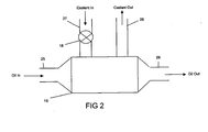
- an oil heat exchanger 16 is mounted externally of the engine and hot lubrication oil is pumped from the engine 11 into the heat exchanger and then cooled oil returned to the engine via conduits 25 & 26 respectively.
- the engine coolant pump outlet 12B is also connected to the heating/cooling system of the heat exchanger 16 via a conduit 27 and the coolant returned to the engine via conduit 28 which in turn is connected into conduit 24.
- the heat exchanger may be any suitable type of exchanger. In the present example a shell and tube exchanger is shown in Fig. 2.
- the coolant is also fed from the hot side of the thermostatic valve 14 through the radiator 13 and back to the coolant pump inlet.
- the volume flow of coolant direct to the heat exchanger 16 is controlled by a control valve 18.
- the control valve 18 may be operated by vacuum or electrically through a programmable electrical controller 19 which may be a part of the engine control unit and the valve should fail in an open condition.
- the controller 19 monitors engine conditions through a number of sensors, for example an oil temperature sensor 31 and a cylinder head metal temperature sensor 32.
- Other useful sensors may include an engine speed sensor, a vehicle speed sensor, an engine load or torque demand sensor, an ambient temperature sensor and a coolant temperature sensor.
- the valve 18 regulates the coolant flow through the heat exchanger 16 in accordance with requirements that are pre-programmed into the controller 19.
- the valve 18 may be controlled by a pulse width modulated signal which controls the valve open position.
- the frequency of the control signal may be the order of 2 pulses /min due to oil temperature changes occurring slowly and the valve should go from the fully open to the fully closed conditions over several seconds in order to avoid water hammer.
- the separate control of the engine coolant through the oil heat exchanger 16 allows for good control without significantly affecting other components of the engine cooling circuit.
- the controller 19 operates the valve 18 such that the valve is open when the vehicle ignition is switched off, or when the ignition is on but the engine is stationary.
- the controller 19 operates according to a general control strategy and in particular:
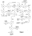
- Fig.3 is a flow chart of a suitable control strategy that is programmed into the controller 19.
- the controller 19 is sensing the oil temperature and coolant temperatures with the engine coolant thermostat opening at T1, e.g. 88° C.
- step 1 determines if the coolant temperature is less than T2, e.g. 60° C. If yes, then step 2 determines if the oil temp is less than T2. If yes, step 3 determines that the valve 18 remains closed, i.e. no coolant flow across the exchanger. If at step 2 the oil temp is greater that T2 then the step 4 determines that the valve 18 is fully opened allowing the oil to heat the coolant. This helps increase the coolant temperature to reduce CO and HC emissions due to hotter combustion chamber temperatures..
- step 5 determines if the oil temp is also less than T2 and if so step 6 determines the valve 18 is fully open allowing the coolant to heat the oil. If at step 5 the oil temperature is greater than T2, then step 7 determines if the coolant temperature is below T3, e.g. 84°C, that is just below the engine thermostat opening temperature T. If the coolant temperature is below T3 (in this example that is between 60-84°), step 8 determines if the oil temperature is less than the coolant temperature and, if so, step 9 determines that the valve 18 is opened for full flow so that the coolant heats the oil.
- T3 e.g. 84°C
- step 10 determines if the oil temperature is less than T4, e.g. 110°C. When the oil temperature is less than T4, step 11 determines the valve 18 remains closed allowing the oil temperature to rise to the optimum operating band.
- step 12 determines if the oil temperature is less than T5 e.g. 125° and if so step 13 causes the position of valve 18 to be modulated to keep the oil temperature at a set temperature T6 e.g. about 118°.
- step 14 determines the valve 18 is fully open to cool the oil to the desired operating temperature.
- the steps 5-14 are operating within an engine coolant temperature range of 60-84°C to reduce CO 2 and NO X formation and increase fuel efficiency.
- step 15 determines if the oil temperature is below T3. If the oil temperature is below then step 16 opens the valve 18 to transfer heat from coolant to the oil.
- step 15 determines the oil temperature is above T3, then step 17 determines if the oil temperature is less than T4.
- step 18 determines if the oil temperature is less than the coolant temperature. If the oil temperature at step 18 is less than the coolant temperature then step 19 determines that the valve 18 is fully open so that the coolant heats the oil and if the oil temperature is above the coolant temperature then step 20 closes the valve 18 preventing the oil from being over cooled and/or allowing the oil temperature to rise to T6.
- step 21 determines if the oil temperature is less than T5. If the oil temperature is below T5 then step 22 modulates the valve 18 to maintain an oil temperature of T6 and if the oil temperature is above T5 then step 23 causes the valve 18 to fully open to cause the coolant flow to reduce the oil temperature towards T6.
- the steps 15-23 are operating with a coolant temperature above T3 to limit CO 2 and NO X emissions.
- Maintaining an oil temperature in the range 110-125°C helps prolong oil life, improves wear characteristics and prevents emulsions forming in the oil due to water vapour present in the blow-by gases.
Landscapes
- Engineering & Computer Science (AREA)
- Mechanical Engineering (AREA)
- General Engineering & Computer Science (AREA)
- Chemical & Material Sciences (AREA)
- Combustion & Propulsion (AREA)
- Lubrication Of Internal Combustion Engines (AREA)
Abstract
Description
- This invention relates to a method and system for cooling of lubrication oil in internal combustion engines and in particular to the cooling or heating of Diesel engine lubrication systems of motor vehicles.
- In order to improve the environment, it is highly desirable to reduce the emissions from Diesel engines and large efforts are being expended to improve fuel economy and reduce particulate and gaseous emissions. Modern Diesel engines for light commercial vehicles and passenger cars are typically provided with turbochargers, and may also be provided with intercoolers. The heat produced by these engines is such that the lubrication oil needs to be cooled to prevent degradation and consequent engine wear, and the oil is therefore passed through a heat exchanger which may in turn be cooled by air flow or by the engine coolant. The present systems cool the oil continuously and therefore the oil is overcooled in all but relatively high load hot climatic temperature conditions.
- That portion of the fuel consumption of an engine due to friction within the engine is influenced by the oil temperature (due to viscosity reducing with increasing temperature) and therefore there are conflicting requirements between the improvement of fuel consumption and the cooling of the lubrication oil.
- HC and CO emissions are particularly high at engine start-up and the catalytic converter will be inoperative because the catalyst temperature will be below its light-off temperature.
- The present invention provides a simple way to improve both fuel consumption and engine emissions by the control of engine oil temperature and rate of rise of coolant temperature from cold.
- According to a first aspect of the present invention there is provided a method of controlling the warming and cooling of lubrication oil for an internal combustion engine in which method the engine coolant and engine oil are separately circulated through a mutual heat exchanger, characterised in that the mutual exchange of heat between the oil and coolant is controlled by controlling the flow of at least one of the oil and coolant through the heat exchanger in accordance with their respective temperatures in relation to predetermined set temperatures.
- Preferably only the flow of engine coolant through the heat exchanger is controlled in accordance with said relative temperatures.
- There is little or no flow of coolant through the heat exchanger when the coolant temperature and oil temperature are below a predetermined first temperature, typically 60°C. This allows the coolant to warm up as fast as possible without transferring heat to the oil and leads to a faster cylinder bore and head warm up and reduced levels of CO and HC emissions.
- Preferably when either of the oil or coolant temperatures exceeds said first temperature there is full flow of coolant provided that either one of the coolant temperature and oil temperature is less than a predetermined second temperature, typically 84°C, and the oil temperature is less than the coolant temperature. Thus the hot coolant is used to heat the oil until the oil and engine are at substantially the same temperature. This will help reduce friction and improve fuel economy. Once oil and coolant are close to the second temperature, typically just below the thermostat initial opening temperature, i.e. 84 °C, the oil temperature is normally held back by the coolant. To allow the oil temperature to rise above the coolant temperature then no coolant flow is allowed until the oil temperature is in the desired oil operating range, typically 110-125° C.
- If the oil is in the desired operating range, modulated flow is preferably used to maintain the oil temperature within the desired range.
- Preferably, when either of the oil or coolant temperatures exceeds said first temperature and provided that one of the oil temperature and coolant temperature is greater than the other of said temperatures then the flow of coolant is controlled in accordance with the relative value of oil temperature relative to further preset higher temperature values, typically 110°C and 125°C. Preferably, the coolant temperature is less than the predetermined second temperature and the oil temperature is greater than the coolant temperature and, in some cases, the coolant temperature is higher than a predetermined second temperature and the oil temperature is greater than the coolant temperature.
- The differences between the preset values of oil temperature and actual oil temperature determine the degree of modulation of the coolant flow.
- The oil cooling/heating system is operable only when the vehicle ignition key is switched on and more preferably only when the vehicle engine is running:
- According to a second aspect of the present invention there is provided an engine oil heating/cooling system for an internal combustion engine having an engine cooling system with a coolant pump circulating liquid coolant through cooling system, the oil heating/cooling system comprising a heat exchanger connected to the engine lubrication system for the flow through of engine oil and also being connected to the engine cooling system for the flow through of engine coolant, a control valve controlling the flow of coolant through the heat exchanger and a controller operating the valve and being connected to an oil temperature sensor and a cylinder head metal temperature sensor, the controller operating the valve in response to signals received from the two sensors.
- Preferably, the control valve is located between the pump outlet and the heat exchanger, in which case the coolant inlet for the heat exchanger may be connected to the coolant pump outlet so that coolant flows from the coolant pump to the heat exchanger and the coolant outlet for the heat exchanger is connected to the coolant pump inlet so that coolant returns back to the pump inlet or alternatively to the engine outlet (engine side of the thermostat).
- The control valve may be a vacuum operated valve and is preferably an electrically operated valve operated by a pulse width modulated signal. The valve is preferably a fail open valve.
- The invention will be described by way of example and with reference to the accompanying drawings in which:
- Fig. 1
- is a schematic drawing of an internal combustion engine having an engine oil cooling system according to the present invention,
- Fig. 2
- is a schematic drawing of a heat exchanger used in the system shown in Fig.1, and
- Fig. 3
- is a flow chart showing the operation of the controller for the coolant flow valve used in the system shown in Fig.1.
- With reference to Fig.1 there is shown a motor vehicle
internal combustion engine 11, preferably a Diesel engine, having a cooling jacket through which a liquid coolant (typically a glycol/water mix) is pumped. The engine cooling system includes apump 12 mounted externally of the engine and which may be driven electrically or mechanically. The coolant enters thepump 12 from aradiator 13 viaconduit 21 and is pumped throughoutlet 12B into the engine cooling jacket and then exits the engine via a thermostatically regulated valve orvalves 14. The heated coolant is then returned to theradiator 13 viaconduit 22 for cooling, and some portion of the heated coolant may be diverted viaconduit 23 to a cabin or passengercompartment heater matrix 15. Theheater matrix 15 is connected viaconduit 24 andconduit 21 to thepump 12 for the circulation of coolant back through theengine 11. - Referring also to Fig.2, an
oil heat exchanger 16 is mounted externally of the engine and hot lubrication oil is pumped from theengine 11 into the heat exchanger and then cooled oil returned to the engine viaconduits 25 & 26 respectively. The enginecoolant pump outlet 12B is also connected to the heating/cooling system of theheat exchanger 16 via aconduit 27 and the coolant returned to the engine viaconduit 28 which in turn is connected intoconduit 24. The heat exchanger may be any suitable type of exchanger. In the present example a shell and tube exchanger is shown in Fig. 2. - The coolant is also fed from the hot side of the
thermostatic valve 14 through theradiator 13 and back to the coolant pump inlet. - The volume flow of coolant direct to the
heat exchanger 16 is controlled by acontrol valve 18. Thecontrol valve 18 may be operated by vacuum or electrically through a programmableelectrical controller 19 which may be a part of the engine control unit and the valve should fail in an open condition. Thecontroller 19 monitors engine conditions through a number of sensors, for example anoil temperature sensor 31 and a cylinder headmetal temperature sensor 32. Other useful sensors may include an engine speed sensor, a vehicle speed sensor, an engine load or torque demand sensor, an ambient temperature sensor and a coolant temperature sensor. - The
valve 18 regulates the coolant flow through theheat exchanger 16 in accordance with requirements that are pre-programmed into thecontroller 19. Thevalve 18 may be controlled by a pulse width modulated signal which controls the valve open position. The frequency of the control signal may be the order of 2 pulses /min due to oil temperature changes occurring slowly and the valve should go from the fully open to the fully closed conditions over several seconds in order to avoid water hammer. The separate control of the engine coolant through theoil heat exchanger 16 allows for good control without significantly affecting other components of the engine cooling circuit. - The
controller 19 operates thevalve 18 such that the valve is open when the vehicle ignition is switched off, or when the ignition is on but the engine is stationary. Thecontroller 19 operates according to a general control strategy and in particular: - a) No coolant flow (
valve 18 closed) until coolant temperature or cylinder head metal temperature reached a predetermined temperature, typically within the range 50-65° C. This temperature should be below the thermostat opening temperature. - b) Coolant flows through the exchanger 16 (
valve 18 open) until the oil temperature reaches the coolant temperature. - c) The
valve 18 closes until the oil temperature reaches the optimum temperature band (110-125° C) for fuel economy, engine wear and durability. - d) The oil cooling operation comes into effect once the oil temperature reaches the
upper end of the optimum band and may comprise an on/off cooling cycle or a
low coolant flow /high coolant flow cooling cycle with a built in hysteresis using
oil temperature feedback. A more complicated system utilises pulse width
modulated signals to operate the
valve 18 at different states of closure to keep the oil at a fixed temperature. Preferably the oil temperature should be maintained within a small optimum temperature window. - e) If the oil temperature exceeds a predetermined limit then the
valve 18 is fully open to maximise cooling of the oil. -
- Fig.3 is a flow chart of a suitable control strategy that is programmed into the
controller 19. Thecontroller 19 is sensing the oil temperature and coolant temperatures with the engine coolant thermostat opening at T1, e.g. 88° C. - From a cold engine start up,
step 1 determines if the coolant temperature is less than T2, e.g. 60° C. If yes, then step 2 determines if the oil temp is less than T2. If yes,step 3 determines that thevalve 18 remains closed, i.e. no coolant flow across the exchanger. If atstep 2 the oil temp is greater that T2 then thestep 4 determines that thevalve 18 is fully opened allowing the oil to heat the coolant. This helps increase the coolant temperature to reduce CO and HC emissions due to hotter combustion chamber temperatures.. - If the engine is warm and at
step 1 the coolant temperature is greater than T2, then step 5 determines if the oil temp is also less than T2 and if sostep 6 determines thevalve 18 is fully open allowing the coolant to heat the oil. If atstep 5 the oil temperature is greater than T2, then step 7 determines if the coolant temperature is below T3, e.g. 84°C, that is just below the engine thermostat opening temperature T. If the coolant temperature is below T3 (in this example that is between 60-84°),step 8 determines if the oil temperature is less than the coolant temperature and, if so,step 9 determines that thevalve 18 is opened for full flow so that the coolant heats the oil. If the oil temperature atstep 8 is greater than T3 then step 10 determines if the oil temperature is less than T4, e.g. 110°C. When the oil temperature is less than T4,step 11 determines thevalve 18 remains closed allowing the oil temperature to rise to the optimum operating band. When the oil temperature atstep 10 is above T4 then step 12 determines if the oil temperature is less than T5 e.g. 125° and if so step 13 causes the position ofvalve 18 to be modulated to keep the oil temperature at a set temperature T6 e.g. about 118°. When the oil temperature atstep 12 is above T5 then step 14 determines thevalve 18 is fully open to cool the oil to the desired operating temperature. The steps 5-14 are operating within an engine coolant temperature range of 60-84°C to reduce CO2 and NOX formation and increase fuel efficiency. - When
step 7 determines that the coolant temperature is above T3, then step 15 determines if the oil temperature is below T3. If the oil temperature is below then step 16 opens thevalve 18 to transfer heat from coolant to the oil. Whenstep 15 determines the oil temperature is above T3, then step 17 determines if the oil temperature is less than T4. When the oil temperature atstep 17 is below T4 then step 18 determines if the oil temperature is less than the coolant temperature. If the oil temperature atstep 18 is less than the coolant temperature then step 19 determines that thevalve 18 is fully open so that the coolant heats the oil and if the oil temperature is above the coolant temperature then step 20 closes thevalve 18 preventing the oil from being over cooled and/or allowing the oil temperature to rise to T6. If atstep 17 the oil temperature is above T4 then step 21 determines if the oil temperature is less than T5. If the oil temperature is below T5 then step 22 modulates thevalve 18 to maintain an oil temperature of T6 and if the oil temperature is above T5 then step 23 causes thevalve 18 to fully open to cause the coolant flow to reduce the oil temperature towards T6. The steps 15-23 are operating with a coolant temperature above T3 to limit CO2 and NOX emissions. - Maintaining an oil temperature in the range 110-125°C helps prolong oil life, improves wear characteristics and prevents emulsions forming in the oil due to water vapour present in the blow-by gases.
Claims (16)
- A method of controlling the warming and cooling of lubrication oil for an internal combustion engine (11) in which method the engine coolant and engine oil are separately circulated through a mutual heat exchanger (16), characterised in that the mutual exchange of heat between the oil and coolant is controlled by controlling the flow of at least one of the oil and coolant through the heat exchanger (16) in accordance with their respective temperatures in relation to predetermined set temperatures.
- A method as claimed in Claim 1 in which the flow of engine coolant through the heat exchanger (16) is controlled in accordance with said relative temperatures.
- A method as claimed in Claim 2 wherein there is no flow of coolant when the coolant temperature and oil temperature are below a predetermined first temperature.
- A method as claimed in Claim 3 wherein if either of the oil or coolant temperatures exceeds said first temperature there is full flow of coolant provided that either one of the coolant temperature and oil temperature is less than a predetermined second temperature and the oil temperature is less than the coolant temperature.
- A method as claimed in Claim 3 or Claim 4, wherein if either of the oil or coolant temperatures exceeds said first temperature and provided that one of the oil temperature and coolant temperature is greater than the other of said temperatures then the flow of coolant is controlled in accordance with the relative value of oil temperature relative to further preset higher temperature values.
- A method as claimed in Claim 5 in which the coolant temperature is less than a predetermined second temperature which is higher than said first temperature and the oil temperature is greater than the coolant temperature,
- A method as claimed in Claim 5 or Claim 6 in which the coolant temperature is higher than a predetermined second temperature which is higher that said first temperature and the oil temperature is greater than the coolant temperature.
- A method as claimed in Claim 6 or Claim 7 wherein the preset values determine the degree of modulation of the coolant flow.
- A method as claimed in any one of Claims 1 to 8 and which is operable only when the vehicle ignition key is switched on.
- A method as claimed in Claim 9 and which is operable only when the vehicle engine is running.
- An engine oil heating/cooling system for an internal combustion engine (11) having an engine cooling system with a coolant pump (12) circulating liquid coolant through cooling system, the oil heating/cooling system comprising a heat exchanger (16) connected to the engine lubrication system for the flow through of engine oil and also being connected to the engine cooling system for the flow through of engine coolant, a control valve (18) to control the flow of coolant through the heat exchanger (16) and a controller (19) operating the valve (18), characterised in that the controller (19) is connected to an oil temperature sensor (31) and a cylinder head metal temperature sensor (32), the controller (19) operating the valve (18) in response to signals received from the two sensors.
- A system as claimed in Claim 11, wherein the control valve (18) is located between the pump outlet (12B) and the heat exchanger (16).
- A system as claimed in Claim 11 wherein the coolant inlet for the heat exchanger (16) is connected to the coolant pump outlet (12B) and the coolant outlet for the heat exchanger (16) is connected to the coolant pump inlet.
- A system as claimed in any one of Claims 11 to 13, wherein the valve (18) is an electrically operated valve operated by a pulse width modulated signal.
- A system as claimed in any one of Claims 11 to 14, wherein the valve (18) is a fail open valve.
- An internal combustion engine (11) for a motor vehicle and which comprises an engine cooling system with a coolant pump (12) circulating liquid coolant through cooling system, and an engine oil cooling/heating system as claimed in any one of Claims 11 to 15.
Applications Claiming Priority (2)
| Application Number | Priority Date | Filing Date | Title |
|---|---|---|---|
| GB0224068 | 2002-10-16 | ||
| GB0224068A GB0224068D0 (en) | 2002-10-16 | 2002-10-16 | Engine oil cooling |
Publications (2)
| Publication Number | Publication Date |
|---|---|
| EP1411215A1 true EP1411215A1 (en) | 2004-04-21 |
| EP1411215B1 EP1411215B1 (en) | 2009-01-28 |
Family
ID=9946016
Family Applications (1)
| Application Number | Title | Priority Date | Filing Date |
|---|---|---|---|
| EP20030256433 Expired - Lifetime EP1411215B1 (en) | 2002-10-16 | 2003-10-11 | Engine oil cooling |
Country Status (3)
| Country | Link |
|---|---|
| EP (1) | EP1411215B1 (en) |
| DE (1) | DE60326029D1 (en) |
| GB (1) | GB0224068D0 (en) |
Cited By (4)
| Publication number | Priority date | Publication date | Assignee | Title |
|---|---|---|---|---|
| WO2005113959A1 (en) * | 2004-05-18 | 2005-12-01 | Gm Global Technology Operations, Inc. | Optimized oil cooling system for an internal combustion engine |
| FR2887289A1 (en) * | 2005-06-21 | 2006-12-22 | Peugeot Citroen Automobiles Sa | Internal combustion engine`s oil heat managing device, has comparison and control unit acting on controlled valve based on result of comparison of coolant and oil temperatures provided by monitoring units |
| CN114961960A (en) * | 2021-02-25 | 2022-08-30 | 通用汽车环球科技运作有限责任公司 | Oil heating for enhanced active hot coolant system |
| CN115309209A (en) * | 2022-09-30 | 2022-11-08 | 深圳市安亿达制冷设备有限公司 | High-precision temperature control system and oil type constant temperature unit |
Families Citing this family (2)
| Publication number | Priority date | Publication date | Assignee | Title |
|---|---|---|---|---|
| CN106499462B (en) * | 2016-12-27 | 2022-04-08 | 张明 | Engine oil anti-emulsification system for automobile valve chamber |
| CN109826687B (en) * | 2019-04-08 | 2024-07-12 | 清华大学苏州汽车研究院(吴江) | Lubricating oil temperature control system and method for engine bench test |
Citations (7)
| Publication number | Priority date | Publication date | Assignee | Title |
|---|---|---|---|---|
| US2392723A (en) * | 1945-03-15 | 1946-01-08 | Edward F Chandler | Cooling system for diesel engines |
| US4512300A (en) * | 1984-04-17 | 1985-04-23 | Cummins Engine Company, Inc. | Oil temperature control system for internal combustion engine |
| FR2571431A1 (en) * | 1984-10-09 | 1986-04-11 | Renault Vehicules Ind | Cooling device for an internal combustion engine |
| EP0926322A2 (en) * | 1997-12-24 | 1999-06-30 | Isuzu Motors Limited | Cooling water circulating structure for engines |
| US6053131A (en) * | 1997-04-12 | 2000-04-25 | Bayerische Motoren Werke Aktiengesellschaft | Heat exchanger for liquid heat exchange media |
| GB2362210A (en) * | 2000-05-08 | 2001-11-14 | Ford Global Tech Inc | An engine temperature management system |
| US20020148433A1 (en) * | 2001-04-13 | 2002-10-17 | David Rossiter | Method and apparatus for a lubricant conditioning system |
-
2002
- 2002-10-16 GB GB0224068A patent/GB0224068D0/en not_active Ceased
-
2003
- 2003-10-11 EP EP20030256433 patent/EP1411215B1/en not_active Expired - Lifetime
- 2003-10-11 DE DE60326029T patent/DE60326029D1/en not_active Expired - Lifetime
Patent Citations (7)
| Publication number | Priority date | Publication date | Assignee | Title |
|---|---|---|---|---|
| US2392723A (en) * | 1945-03-15 | 1946-01-08 | Edward F Chandler | Cooling system for diesel engines |
| US4512300A (en) * | 1984-04-17 | 1985-04-23 | Cummins Engine Company, Inc. | Oil temperature control system for internal combustion engine |
| FR2571431A1 (en) * | 1984-10-09 | 1986-04-11 | Renault Vehicules Ind | Cooling device for an internal combustion engine |
| US6053131A (en) * | 1997-04-12 | 2000-04-25 | Bayerische Motoren Werke Aktiengesellschaft | Heat exchanger for liquid heat exchange media |
| EP0926322A2 (en) * | 1997-12-24 | 1999-06-30 | Isuzu Motors Limited | Cooling water circulating structure for engines |
| GB2362210A (en) * | 2000-05-08 | 2001-11-14 | Ford Global Tech Inc | An engine temperature management system |
| US20020148433A1 (en) * | 2001-04-13 | 2002-10-17 | David Rossiter | Method and apparatus for a lubricant conditioning system |
Cited By (6)
| Publication number | Priority date | Publication date | Assignee | Title |
|---|---|---|---|---|
| WO2005113959A1 (en) * | 2004-05-18 | 2005-12-01 | Gm Global Technology Operations, Inc. | Optimized oil cooling system for an internal combustion engine |
| US7717070B2 (en) | 2004-05-18 | 2010-05-18 | Gm Global Technology Operations, Inc. | Optimized cooling system for a motorized vehicle |
| FR2887289A1 (en) * | 2005-06-21 | 2006-12-22 | Peugeot Citroen Automobiles Sa | Internal combustion engine`s oil heat managing device, has comparison and control unit acting on controlled valve based on result of comparison of coolant and oil temperatures provided by monitoring units |
| CN114961960A (en) * | 2021-02-25 | 2022-08-30 | 通用汽车环球科技运作有限责任公司 | Oil heating for enhanced active hot coolant system |
| CN115309209A (en) * | 2022-09-30 | 2022-11-08 | 深圳市安亿达制冷设备有限公司 | High-precision temperature control system and oil type constant temperature unit |
| CN115309209B (en) * | 2022-09-30 | 2022-12-06 | 深圳市安亿达制冷设备有限公司 | High-precision temperature control system and oil type constant temperature unit |
Also Published As
| Publication number | Publication date |
|---|---|
| DE60326029D1 (en) | 2009-03-19 |
| GB0224068D0 (en) | 2002-11-27 |
| EP1411215B1 (en) | 2009-01-28 |
Similar Documents
| Publication | Publication Date | Title |
|---|---|---|
| US6152088A (en) | Cooling system for a motor-vehicle internal combustion engine | |
| US7263954B2 (en) | Internal combustion engine coolant flow | |
| US6758172B2 (en) | Method of engine cooling | |
| JP3179971U (en) | Combustion engine cooling system | |
| US20050202933A1 (en) | Transmission fluid heating using engine exhaust | |
| US20110000188A1 (en) | Heat exchanging systems for motor vehicles | |
| GB2383409A (en) | Motor vehicle comprising an internal combustion engine with additional heating mode | |
| US20080168956A1 (en) | Integrated Engine Thermal Management | |
| EP1170477A2 (en) | Electric waterpump, fluid control valve and electric cooling fan strategy | |
| US10024219B2 (en) | Engine system having coolant control valve | |
| GB2429763A (en) | Cooling system comprising heat exchangers for motor vehicle cold start operation | |
| US7000574B2 (en) | Method of operating a cooling-and heating circuit of a motor vehicle, and a cooling-and heating circuit for a motor vehicle | |
| GB2472228A (en) | Reducing the fuel consumption of an i.c. engine by using heat from an EGR cooler to heat engine oil after cold-starting | |
| US5655506A (en) | System for preheating intake air for an internal combustion engine | |
| EP1249588B1 (en) | Internal combustion engine with regenerator | |
| US5970927A (en) | Apparatus for circulating cooling water for internal combustion engine | |
| US6499442B2 (en) | Integral water pump/electronic engine temperature control valve | |
| EP1411215B1 (en) | Engine oil cooling | |
| JP2005530076A (en) | Cooling circuit for internal combustion engines | |
| US4391407A (en) | Vehicle cabin heater | |
| JP3850873B2 (en) | System for maintaining engine oil at optimum temperature | |
| JPH1082320A (en) | Water-cooled engine cooling structure | |
| KR102451921B1 (en) | Coolant flow control device, cooling system provided with the same and control method for the same | |
| JPH0726955A (en) | Oil temperature control device for vehicle | |
| CN111779562A (en) | Engine cooling system and method |
Legal Events
| Date | Code | Title | Description |
|---|---|---|---|
| PUAI | Public reference made under article 153(3) epc to a published international application that has entered the european phase |
Free format text: ORIGINAL CODE: 0009012 |
|
| AK | Designated contracting states |
Kind code of ref document: A1 Designated state(s): AT BE BG CH CY CZ DE DK EE ES FI FR GB GR HU IE IT LI LU MC NL PT RO SE SI SK TR |
|
| AX | Request for extension of the european patent |
Extension state: AL LT LV MK |
|
| RIN1 | Information on inventor provided before grant (corrected) |
Inventor name: PEGG, IAN |
|
| 17P | Request for examination filed |
Effective date: 20041020 |
|
| AKX | Designation fees paid |
Designated state(s): DE FR GB |
|
| RAP1 | Party data changed (applicant data changed or rights of an application transferred) |
Owner name: FORD GLOBAL TECHNOLOGIES, LLC. |
|
| 17Q | First examination report despatched |
Effective date: 20071008 |
|
| GRAP | Despatch of communication of intention to grant a patent |
Free format text: ORIGINAL CODE: EPIDOSNIGR1 |
|
| GRAS | Grant fee paid |
Free format text: ORIGINAL CODE: EPIDOSNIGR3 |
|
| GRAA | (expected) grant |
Free format text: ORIGINAL CODE: 0009210 |
|
| AK | Designated contracting states |
Kind code of ref document: B1 Designated state(s): DE FR GB |
|
| REG | Reference to a national code |
Ref country code: GB Ref legal event code: FG4D |
|
| REF | Corresponds to: |
Ref document number: 60326029 Country of ref document: DE Date of ref document: 20090319 Kind code of ref document: P |
|
| PLBE | No opposition filed within time limit |
Free format text: ORIGINAL CODE: 0009261 |
|
| STAA | Information on the status of an ep patent application or granted ep patent |
Free format text: STATUS: NO OPPOSITION FILED WITHIN TIME LIMIT |
|
| 26N | No opposition filed |
Effective date: 20091029 |
|
| REG | Reference to a national code |
Ref country code: FR Ref legal event code: PLFP Year of fee payment: 14 |
|
| REG | Reference to a national code |
Ref country code: FR Ref legal event code: PLFP Year of fee payment: 15 |
|
| REG | Reference to a national code |
Ref country code: FR Ref legal event code: PLFP Year of fee payment: 16 |
|
| PGFP | Annual fee paid to national office [announced via postgrant information from national office to epo] |
Ref country code: FR Payment date: 20190924 Year of fee payment: 17 |
|
| PGFP | Annual fee paid to national office [announced via postgrant information from national office to epo] |
Ref country code: GB Payment date: 20190925 Year of fee payment: 17 |
|
| PGFP | Annual fee paid to national office [announced via postgrant information from national office to epo] |
Ref country code: DE Payment date: 20190917 Year of fee payment: 17 |
|
| REG | Reference to a national code |
Ref country code: DE Ref legal event code: R119 Ref document number: 60326029 Country of ref document: DE |
|
| GBPC | Gb: european patent ceased through non-payment of renewal fee |
Effective date: 20201011 |
|
| PG25 | Lapsed in a contracting state [announced via postgrant information from national office to epo] |
Ref country code: DE Free format text: LAPSE BECAUSE OF NON-PAYMENT OF DUE FEES Effective date: 20210501 Ref country code: FR Free format text: LAPSE BECAUSE OF NON-PAYMENT OF DUE FEES Effective date: 20201031 |
|
| PG25 | Lapsed in a contracting state [announced via postgrant information from national office to epo] |
Ref country code: GB Free format text: LAPSE BECAUSE OF NON-PAYMENT OF DUE FEES Effective date: 20201011 |