EP1410815B1 - Self purging angiographic injector - Google Patents
Self purging angiographic injector Download PDFInfo
- Publication number
- EP1410815B1 EP1410815B1 EP03028317A EP03028317A EP1410815B1 EP 1410815 B1 EP1410815 B1 EP 1410815B1 EP 03028317 A EP03028317 A EP 03028317A EP 03028317 A EP03028317 A EP 03028317A EP 1410815 B1 EP1410815 B1 EP 1410815B1
- Authority
- EP
- European Patent Office
- Prior art keywords
- port
- valve
- patient
- medical fluid
- flow
- Prior art date
- Legal status (The legal status is an assumption and is not a legal conclusion. Google has not performed a legal analysis and makes no representation as to the accuracy of the status listed.)
- Expired - Lifetime
Links
Images


Classifications
-
- A—HUMAN NECESSITIES
- A61—MEDICAL OR VETERINARY SCIENCE; HYGIENE
- A61M—DEVICES FOR INTRODUCING MEDIA INTO, OR ONTO, THE BODY; DEVICES FOR TRANSDUCING BODY MEDIA OR FOR TAKING MEDIA FROM THE BODY; DEVICES FOR PRODUCING OR ENDING SLEEP OR STUPOR
- A61M5/00—Devices for bringing media into the body in a subcutaneous, intra-vascular or intramuscular way; Accessories therefor, e.g. filling or cleaning devices, arm-rests
- A61M5/14—Infusion devices, e.g. infusing by gravity; Blood infusion; Accessories therefor
- A61M5/142—Pressure infusion, e.g. using pumps
- A61M5/14212—Pumping with an aspiration and an expulsion action
- A61M5/14216—Reciprocating piston type
-
- A—HUMAN NECESSITIES
- A61—MEDICAL OR VETERINARY SCIENCE; HYGIENE
- A61M—DEVICES FOR INTRODUCING MEDIA INTO, OR ONTO, THE BODY; DEVICES FOR TRANSDUCING BODY MEDIA OR FOR TAKING MEDIA FROM THE BODY; DEVICES FOR PRODUCING OR ENDING SLEEP OR STUPOR
- A61M31/00—Devices for introducing or retaining media, e.g. remedies, in cavities of the body
- A61M31/005—Devices for introducing or retaining media, e.g. remedies, in cavities of the body for contrast media
-
- A—HUMAN NECESSITIES
- A61—MEDICAL OR VETERINARY SCIENCE; HYGIENE
- A61M—DEVICES FOR INTRODUCING MEDIA INTO, OR ONTO, THE BODY; DEVICES FOR TRANSDUCING BODY MEDIA OR FOR TAKING MEDIA FROM THE BODY; DEVICES FOR PRODUCING OR ENDING SLEEP OR STUPOR
- A61M5/00—Devices for bringing media into the body in a subcutaneous, intra-vascular or intramuscular way; Accessories therefor, e.g. filling or cleaning devices, arm-rests
- A61M5/14—Infusion devices, e.g. infusing by gravity; Blood infusion; Accessories therefor
- A61M5/142—Pressure infusion, e.g. using pumps
- A61M5/145—Pressure infusion, e.g. using pumps using pressurised reservoirs, e.g. pressurised by means of pistons
- A61M5/1452—Pressure infusion, e.g. using pumps using pressurised reservoirs, e.g. pressurised by means of pistons pressurised by means of pistons
- A61M5/14546—Front-loading type injectors
-
- A—HUMAN NECESSITIES
- A61—MEDICAL OR VETERINARY SCIENCE; HYGIENE
- A61M—DEVICES FOR INTRODUCING MEDIA INTO, OR ONTO, THE BODY; DEVICES FOR TRANSDUCING BODY MEDIA OR FOR TAKING MEDIA FROM THE BODY; DEVICES FOR PRODUCING OR ENDING SLEEP OR STUPOR
- A61M5/00—Devices for bringing media into the body in a subcutaneous, intra-vascular or intramuscular way; Accessories therefor, e.g. filling or cleaning devices, arm-rests
- A61M5/14—Infusion devices, e.g. infusing by gravity; Blood infusion; Accessories therefor
- A61M5/168—Means for controlling media flow to the body or for metering media to the body, e.g. drip meters, counters ; Monitoring media flow to the body
- A61M5/172—Means for controlling media flow to the body or for metering media to the body, e.g. drip meters, counters ; Monitoring media flow to the body electrical or electronic
-
- A—HUMAN NECESSITIES
- A61—MEDICAL OR VETERINARY SCIENCE; HYGIENE
- A61M—DEVICES FOR INTRODUCING MEDIA INTO, OR ONTO, THE BODY; DEVICES FOR TRANSDUCING BODY MEDIA OR FOR TAKING MEDIA FROM THE BODY; DEVICES FOR PRODUCING OR ENDING SLEEP OR STUPOR
- A61M5/00—Devices for bringing media into the body in a subcutaneous, intra-vascular or intramuscular way; Accessories therefor, e.g. filling or cleaning devices, arm-rests
- A61M5/14—Infusion devices, e.g. infusing by gravity; Blood infusion; Accessories therefor
- A61M2005/1401—Functional features
- A61M2005/1403—Flushing or purging
-
- A—HUMAN NECESSITIES
- A61—MEDICAL OR VETERINARY SCIENCE; HYGIENE
- A61M—DEVICES FOR INTRODUCING MEDIA INTO, OR ONTO, THE BODY; DEVICES FOR TRANSDUCING BODY MEDIA OR FOR TAKING MEDIA FROM THE BODY; DEVICES FOR PRODUCING OR ENDING SLEEP OR STUPOR
- A61M2205/00—General characteristics of the apparatus
- A61M2205/35—Communication
- A61M2205/3546—Range
- A61M2205/3561—Range local, e.g. within room or hospital
-
- A—HUMAN NECESSITIES
- A61—MEDICAL OR VETERINARY SCIENCE; HYGIENE
- A61M—DEVICES FOR INTRODUCING MEDIA INTO, OR ONTO, THE BODY; DEVICES FOR TRANSDUCING BODY MEDIA OR FOR TAKING MEDIA FROM THE BODY; DEVICES FOR PRODUCING OR ENDING SLEEP OR STUPOR
- A61M2209/00—Ancillary equipment
- A61M2209/01—Remote controllers for specific apparatus
-
- A—HUMAN NECESSITIES
- A61—MEDICAL OR VETERINARY SCIENCE; HYGIENE
- A61M—DEVICES FOR INTRODUCING MEDIA INTO, OR ONTO, THE BODY; DEVICES FOR TRANSDUCING BODY MEDIA OR FOR TAKING MEDIA FROM THE BODY; DEVICES FOR PRODUCING OR ENDING SLEEP OR STUPOR
- A61M2230/00—Measuring parameters of the user
- A61M2230/04—Heartbeat characteristics, e.g. ECG, blood pressure modulation
-
- A—HUMAN NECESSITIES
- A61—MEDICAL OR VETERINARY SCIENCE; HYGIENE
- A61M—DEVICES FOR INTRODUCING MEDIA INTO, OR ONTO, THE BODY; DEVICES FOR TRANSDUCING BODY MEDIA OR FOR TAKING MEDIA FROM THE BODY; DEVICES FOR PRODUCING OR ENDING SLEEP OR STUPOR
- A61M5/00—Devices for bringing media into the body in a subcutaneous, intra-vascular or intramuscular way; Accessories therefor, e.g. filling or cleaning devices, arm-rests
- A61M5/14—Infusion devices, e.g. infusing by gravity; Blood infusion; Accessories therefor
- A61M5/168—Means for controlling media flow to the body or for metering media to the body, e.g. drip meters, counters ; Monitoring media flow to the body
- A61M5/172—Means for controlling media flow to the body or for metering media to the body, e.g. drip meters, counters ; Monitoring media flow to the body electrical or electronic
- A61M5/1723—Means for controlling media flow to the body or for metering media to the body, e.g. drip meters, counters ; Monitoring media flow to the body electrical or electronic using feedback of body parameters, e.g. blood-sugar, pressure
Abstract
Description
- This invention relates to angiography and more specifically, the injector used to inject a medical fluid such as radiographic contrast material into living organisms.
- One of the major systems in the human body is the circulatory system. The major components of the circulatory system are the heart, blood vessels, and the blood, all of which are vital to the transportation of materials between the external environment and the different cells and tissues of the human body.
- The blood vessels are the network of passageways through which the blood travels in the human body. Specifically, arteries carry the oxygenated blood away from the left ventricle of the heart. These arteries are aligned in progressively decreasing diameter and pressure capability from the aorta, which carries the blood immediately out of the heart to other major arteries, to smaller arteries, to arterioles, and finally to tiny capillaries, which feed the cells and tissues of the human body. Similarly, veins carry the oxygen depleted blood back to the right atrium of the heart using a progressively increasing diameter network of venules and veins.
- If the heart chambers, valves, arteries, veins or other capillaries connected thereto are either abnormal (such as from a birth defect), restricted (such as from atherosclerotic plaque buildup), or deteriorating (such as from aneurism formation), then a physician may need to examine the heart and connected network of vessels. The physician may also need to correct any problems encountered during the examination with a catheter or similar medical instrument.
- Angiography is a procedure used in the detection and treatment of abnormalities or restrictions in blood vessels. During angiography, a radiographic image of a vascular structure is obtained by injecting radiographic contrast material through a catheter into a vein or artery. The vascular structures fluidly connected with the vein or artery in which the injection occurred are filled with contrast material. X-rays are passed through the region of the body in which the contrast material was injected. The X-rays are absorbed by the contrast material, causing a radiographic outline or image of the blood vessel containing the contrast material. The x-ray images of the blood vessels filled with contrast material are usually recorded onto film or videotape and are displayed on a fluoroscope monitor.
- Angiography gives the doctor an image of the vascular structures in question. This image may be used solely for diagnostic purposes, or the image may be used during a procedure such as angioplasty where a balloon is inserted into the vascular system and inflated to open a stenosis caused by atherosclerotic plaque buildup.
- Currently, during angiography, after a physician places a catheter into a vein or artery (by direct insertion into the vessel or through a skin puncture site), the angiographic catheter is connected to either a manual or an automatic contrast injection mechanism.
- A simple manual contrast injection mechanism typically has a syringe and a catheter connection. The syringe includes a chamber with a plunger therein. Radiographic contrast material is suctioned into the chamber. Any air is removed by actuating the plunger while the catheter connection is facing upward so that any air, which floats on the radiographic contrast material, is ejected from the chamber into the air. The catheter connection is then attached to a catheter that is positioned in a vein or artery in the patient.
- The plunger is manually actuated to eject the radiographic contrast material from the chamber, through the catheter, and into a vein or artery. The user of the manual contrast injection mechanism may adjust the rate and volume of injection by altering the manual actuation force applied to the plunger.
- Often, more than one type of fluid injection is desired, such as a saline flush followed by the radiographic contrast material. One of the most common manual injection mechanisms used today includes a valve mechanism which controls which of the fluids will flow into the valving mechanism and out to the catheter within the patient. The valve mechanism contains a plurality of manual valves that the user operates manually to open and close that particular fluid channel. When the user suctions or injects contrast fluid into the chamber, the fluid is pulled from the valve mechanism via the open valves. By changing the valve positions, another fluid may be injected.
- These manual injection mechanisms are typically hand actuated. This allows user control over the quantity and pressure of the injection. However, all of the manual systems are only capable of injecting the radiographic contrast material at maximum pressure that can be applied by the human hand (i.e., 150 p.s.i & i.e. 10,5 bar). Also, the quantity of radiographic contrast material is typically limited to a maximum of about 12cc. Finally, there are no safety limits on these manual contrast injection mechanisms which act to restrict or stop injections that are outside of reasonable parameters (such as rate or pressure) and no active sensors to detect air bubbles or other hazards.
- Currently used motorized injection devices consist of a syringe connected to a linear actuator. The linear actuator is connected to a motor, which is controlled electronically. The operator enters into the electronic control a fixed volume of contrast material to be injected at a fixed rate of injection. The fixed rate of injection consists of a specified initial rate of flow increase and a final rate of injection until the entire volume of contrast material is injected. There is no interactive control between the operator and machine, except to start or stop the injection. Any change in flow rate must occur by stopping the machine and resetting the parameters.
- The lack of ability to vary the rate of injection during the injection results in suboptimal quality of angiographic studies. This is because the optimal flow rate of injections varies considerably between patients. In the cardiovascular system, the rate and volume of contrast injection is dependent on the size of and blood flow rate within the chamber or blood vessel being injected. In many or most cases, these parameters are not known precisely. Moreover, the optimal rate of injection can change rapidly, as the patient's condition changes in response to drugs, illness, or normal physiology. Consequently, the initial injection of contrast material may be insufficient in flow rate to outline the structure on x-ray imaging, necessitating another injection. Conversely, an excessive flow rate might injure the chamber or blood vessel being injected, cause the catheter to be displaced (from the jet of contrast material exiting the catheter tip), or lead to toxic effects from contrast overdose (such as abnormal heart rhythm).
- At present, the operator can choose between two systems for injecting contrast material: a manual injection system which allows for a variable, operator interactive flow rate of limited flow rate and a preprogrammed motorized system without operator interactive feedback (other than the operator can start/stop the procedure).
- The present invention is an apparatus for delivering medical fluids such as angiographic radiographic contrast material to a patient. In one preferred embodiment, the apparatus is a dual port syringe which preferably features a self purging operation to eliminate air. The apparatus of the present invention includes an inlet port for connection to a fluid reservoir, a syringe and a valve connected in a flow path between the supply port and the syringe. During a fill operation, the medical fluid is drawn from the fluid reservoir through the first valve and into the syringe by rearward movement of the syringe plunger or piston. During a purge operation, the piston is moved forward to expel air through the first valve to the inlet port. The first valve permits air flow through the flow path from the syringe to the inlet port, but blocks flow of medical fluid back to the inlet port.
- The apparatus also include, and preferred embodiments, a second valve which is connected between the syringe and the patient. The second valve is in a closed state during the fill and air purge operation. When an injection is to be performed, the second valve opens to permit flow of the medical fluid under pressure from the syringe to the patient. At the same time, the first valve prevents flow of a medical fluid from the syringe to the inlet port. The preferred dual port syringe includes a syringe body, a piston which is reciprocally movable in the syringe body, and upper and lower ports. The upper port is connected to a fluid reservoir so that medical fluid is drawn from the fluid reservoir through the upper port into the syringe body when the piston moves in a rearward direction. The lower port is connected to a device, such as a catheter, through which the medical fluid is delivered under pressure to the patient. When the piston moves in a forward direction, medical fluid is delivered under pressure out of the syringe body through the lower port.
-
-
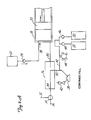
Fig. 1 is a perspective view illustrating a preferred embodiment of the angiographic injector system of the present invention. -
Figs. 2A-2G are diagrams illustrating operations of the system ofFig. 1 . -
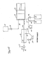
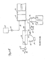
Fig. 3 is an electrical block diagram of the control system of the injector system ofFig. 1 . -
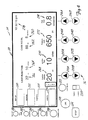
Fig. 4 illustrates front panel controls and displays of a preferred embodiment of the injector system of the present invention. -
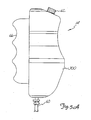
Figs. 5A and5B are side and partial top perspective views of the remote control of the system ofFig. 1 . -
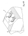
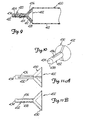
Fig. 6 is a perspective view of a foot operated remote control. -
Figs. 7A-7D illustrate the operation of the inlet check valve and manifold during contrast fill, air purge, and patient inject operations. -
Figs. 8A-8C illustrate operation of the inlet check valve in greater detail. -
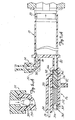
Fig. 9 shows a conventional syringe body adapted for dual port operation. -
Fig. 9 is a perspective view of an adaptor insert used in the dual port syringe ofFig. 9 . -
Figs. 11A - 11B are top and side views of the adaptor insert of Fig. -
Figure 1 showsangiographic injector system 10 for injecting radiographic contrast material into a blood vessel under interactive physician control.System 10 includesmain console 12, hand heldremote control 14,syringe holder 16,syringe body 18,syringe plunger 20, radiographic material reservoir (bottle) 22, one-way valve 24,manifold 26,high pressure tube 28,catheter 30,patient medication port 32, three-way stop-cock 34, T-connector 36,pressure transducer 38, stop-cock 40.tubing 42,peristaltic pump 44,saline check valve 46,waste check valve 48.saline bag 50,waste bag 52, andbag support rack 54. - Console 12 houses the electrical controls for
system 10, together with the motors which drivepiston 20 andperistaltic pump 44. On the front surface ofconsole 12,user interface 54 provides control switches 56 anddisplay 58 through which the user may enter control settings and monitor the operational state ofsystem 10. -
Remote control 14 is connected to console 12 by cable 60 (although in other embodimentsremote control 14 may be connected by a wireless connection such as an RF, infrared, optic, or ultrasonic link).Remote control 14 is, in the embodiment shown inFig. 1 , a hand-held control which includes reset and saline push button switches 62 and 64, respectively, and flow rate control lever ortrigger 66. By squeezingtrigger 66, the user can provide a command signal to console 12 to provide a continuously variable injection rate. -
Syringe holder 16 projects from the left hand side ofconsole 12.Syringe holder 16 is preferably a clear material, and includes a halfcylindrical back shell 68, a half cylindrical front door 70 (which is shown in open position inFig. 1 ), andreservoir holder 72. -
Syringe 18 is a transparent or translucent plastic cylinder having itsopen end 74 connected to console 12.Closed end 76 ofsyringe 18 contains two ports:upper port 78 andlower port 80. -
Plunger 20 is movable withinsyringe body 18.Plunger 20 is connected to, and driven by a motor located withinconsole 12. - Radiographic
contrast material reservoir 22 is connected through one-way check valve 24 toupper port 78. Radiographic contrast material is drawn fromreservoir 22 throughcheck valve 24 andupper port 78 into the pumping chamber defined bysyringe body 18 andplunger 20. Checkvalve 24 is preferably a weighted one-way valve which permits air to flow fromsyringe body 18 back intoreservoir 22, but will not permit radiographic contrast material to flow fromsyringe body 18 toreservoir 22. This permits automatic purging of air from the system, as will be described in more detail later. -
Lower port 80 ofsyringe body 18 is connected tomanifold 26.Manifold 26 includes a spring biased spool valve which normally connects transducer/saline port 82 andpatient port 84. When radiographic contrast material is to be injected, the pressure of the radiographic material causes the spool valve to change states so thatlower port 80 is connected topatient port 84. -
High pressure tube 28 is a flexible tube which connectspatient port 84 tocatheter 30. Three-way stop-cock 34 is located at the distal end oftube 28. Rotatableluer lock connector 86 is connected to stop-cock 34 and mates withluer connector 88 at the proximal end ofcatheter 30. Stop-cock 34 either blocks flow betweentube 28 andcatheter 30, permits flow, or connectsmedication port 32 tocatheter 30. - In addition to injecting radiographic material into a patient through
catheter 30,system 10 also permits other related functions to be performed. A device for delivering the patient medication (not shown inFig. 1 ) may be connected tomedication port 32 when medication is to be delivered throughcatheter 30 to the patient. - When
catheter 30 is in place in the patient, and an injection of radiographic contrast material is not taking place,pressure transducer 38 monitors the blood pressure through the column of fluid which extends fromcatheter 30,tube 28,patient port 84,manifold 26, transducer/saline port 82,tubing 90, T-connector 36, andtubing 92.Transducer 38 has an associated stop-cock 40 which allowstransducer 38 to be exposed to atmospheric pressure during calibration and also allows for removal/expulsion of trapped air so the dome chamber oftransducer 38 can be flushed with saline. -
Peristaltic pump 44 supplies saline solution frombag 50 throughsaline check valve 46,tubing 42, T-connector 36 andtubing 90 tosaline port 82. Whenperistaltic pump 44 is operating to supply saline solution, the saline solution is supplied throughmanifold 26 topatient port 84 and then throughtube 28 tocatheter 30. -
Peristaltic pump 44 also operates in an opposite direction to draw fluid fromcatheter 30 and throughtube 28,manifold 26,tubing 90, T-connector 36 andtubing 42 to wastecheck valve 48 and then intowaste collection bag 52. - In a preferred embodiment of the present invention,
syringe body 18,manifold 26,tube 28,catheter 30, T-connector 36,tubing 42,check valves bags tubing system 10 each time an angiography procedure is to be performed with a new patient. Oncesystem 10 is set up with all the disposable items installed,door 70 is closed, andsyringe body 18 filled with contrast material and purged of air, the user (typically a physician) enters intosystem 10 the safety parameters that will apply to the injection of radiographic contrast material. These safety parameters typically include the maximum amount of radiographic contrast material to be injected during any one injection, the maximum flow rate of the injection, the maximum pressure developed withinsyringe body 18, and the maximum rise time or acceleration of the injection. To actuate an injection of contrast material, the user operatesremote control 14 by squeezingtrigger 66. Within the preset safety parameters,system 10 causes the flow rate of the injection to increase as the force or distance of travel oftrigger 66 is increased. - Typically, the user will meter the amount and rate of contrast material injected based upon continuous observation of the contrast outflow into the structure being injected using fluoroscopy or other imaging methods.
System 10 allows the user to tailor the contrast injections to the needs of the patient, thereby maximizing the quality of the procedure, increasing the safety, and reducing the amount of contrast material required to perform the fluoroscopic examination. -
Figs. 2A-2G are diagrams illustrating fluid flow paths during seven different operations ofsystem 10. Those operations are contrast fill (Fig. 2A ), air purge (Fig. 2B ), patient inject (Fig. 2C ), patient pressure (Fig. 2D ). saline flush (Fig. 2E ), aspirate waste (Fig. 2F ), and medicate patient (Fig. 2G ). - The contrast fill operation illustrated in
Fig. 2A involves the filling ofsyringe body 18 with radiographic contrast material from reservoir (contrast media supply) 22. The contrast fill operation is performed during initial set up ofsystem 10, and may be repeated during operation ofsystem 10 wheneversyringe body 18 is running low on radiographic contrast material. - During initial set up of
system 10,plunger 20 is initially driven to its furthest forward position adjacentclosed end 76 ofsyringe body 18. This will expel to the atmosphere the majority of the air which is located withinsyringe body 18. -
Plunger 20 is then retracted, which creates a vacuum withinsyringe body 18 which draws contrast material fromreservoir 22 throughcheck valve 24 intosyringe body 18 throughupper port 78. - The Contrast Fill operation typically will result in some air being drawn into or remaining within
syringe body 18. It is important, of course, to prevent air from being injected into the patient throughcatheter 30. That is the purpose of the Air Purge operation shown inFig. 2B . Also, the location of two ports at different elevations allows for a greater amount of safety in preventing air bubbles in the injection. - During the Air Purge operation,
plunger 20 travels forward to expel trapped air withinsyringe body 18. The air, being lighter than the contrast material, gathers near the top ofsyringe body 18. Asplunger 20 moves forward, the air is expelled fromsyringe body 18 throughupper port 78 and one-way valve 24. In the embodiment illustrated inFig. 2B , one-way valve 24 is a weighted one-way valve which allows flow of radiographic contrast material fromreservoir 22 toupper port 78, but will not allow radiographic contrast material to flow in the opposite direction fromupper port 78 toreservoir 22.Valve 24 will, however, allow air to flow fromport 78 toreservoir 22. As soon as radiographic contrast material begins flowing out ofsyringe body 18 throughupper port 78 tovalve 24,valve 24 closes to prevent any further flow towardreservoir 22. -
Valve 24 can also, in alternative embodiments, can be a solenoid actuated or motor driven valve operated under control of the electric circuitry withinconsole 12. In either case,valve 24 is capable to withstanding the relatively high pressures to which it will be subjected during the inject operation. Preferably,valve 24 is capable of withstanding static fluid pressures up to about 1200 p.s.i. -
Fig. 2C illustrates the Patient Inject operation.Plunger 20 travels forward under the interactive control of the user, who is controllingtrigger 66 ofremote control 14. The movement ofplunger 20 creates hydraulic pressure to force contrast material out ofsyringe body 18 throughlower port 80 and throughmanifold 26 andhigh pressure tube 28 intocatheter 30. As shown inFig. 2C , syringelower port 80 andpatient port 84 are connected for fluid flow during the patient inject operation. -
Manifold 26 contains a valve which controls the routing of fluid connections betweenpatient port 84 and eithersyringe bottom port 80 or transducer/saline port 82. In one embodiment of the present invention,manifold 26 includes a spool valve which is spring biased so thatpatient port 84 is normally connected to transducer/saline port 82 (as illustrated inFigs. 2A and2B ). When the pressure atsyringe bottom port 80 builds with the movement ofplunger 20 forward, the bias force against the spool valve is overcome so thatsyringe bottom port 80 is connected topatient port 84, and transducer/saline port 82 is disconnected the valve withinmanifold 26 protectspressure transducer 38 from being exposed to the high pressure generated by the patient inject operation. - The spool valve opens automatically during the patient inject operation in response to increase pressure exerted on it from the syringe
lower port 80. The spool valve closes and returns to its original position allowing for connection ofpatient port 84 totransducer 38 when a slight vacuum is applied by retraction ofplunger 20 at the end of each Patient Inject operation. - In an alternative embodiment, the valve within
manifold 26 is an electromechanical or motor driven valve which is actuated at appropriate times to connect either syringelower port 80 or transducer/saline port 82 topatient port 84. The actuator mechanism is controlled byconsole 12. Once again in this alternative embodiment, the valve protectspressure transducer 38 from being exposed to high pressure. -
Fig. 2D illustrates the Patient Pressure operation.System 10 allows for reading of the patient's blood pressure, which is monitored throughcatheter 30. Patient blood pressure can be monitored through the use ofpressure transducer 38 at any time except during the patient inject, saline flush, and waste aspirate operations. The pressure reading being produced bypressure transducer 38 may be normalized by manually opening stop-cock 40 and closing stop-cock 34 to exposepressure transducer 38 to atmospheric pressure. - During the Saline Flush operation illustrated in
Fig. 2E , saline solution is used to flush all of the internal lines,pressure transducer chamber 38,tube 28, andcatheter 30. As shown inFig. 2E ,peristaltic pump 44 is operating in a direction which causes saline solution to be drawn frombag 50 throughcheck valve 46 and throughtubing 42 tosaline port 82.Manifold 26 connectssaline port 82 topatient port 84 so that saline solution is pumped out ofpatient port 84 and throughtube 28 andcatheter 30. - During the Aspirate Waste operation,
patient port 84 is again connected tosaline port 82. During this operation,peristaltic pump 44 is operating in the opposite direction from its rotation during the saline flush operation. As a result, patient fluids are aspirated frompatient port 84 tosaline port 82 and then throughtubing 42 andcheck valve 48 intowaste collection bag 52.Peristaltic pump 44 acts as a valve pinching/occludingtubing 42 and preventing back flow to/from saline andwaste containers check valves - With
catheter 30 in place within the patient, it may be desirable to supply patient medication.System 10 allows for that option by providingpatient medication port 32. As shown inFig. 2G , when stop-cock 34 is open, a medication source connected to port 32 will be connected topatient port 84, and thereby tocatheter 30. During the medicate patient operation,peristaltic pump 44 andplunger 20 are not moving. -
Fig. 3 is an electrical block diagram of the control system which controls the operation ofangiographic injector system 10. The electrical control system includesdigital computer 100, which receives input signals fromremote control 14 and front panel controls 56 throughinterface 102, and provides signals to display 58 to display operation data, alerts, status information and operator prompts. -
Computer 100 controls the motion ofplunger 20 through a motor drive circuit which includesmotor 104,motor amplifier 106,tachometer 108,potentiometer 110, arectifier 112, pressure sensingload cell 114, and A/D converter 160. -
Motor amplifier 106 provides aDrive 1 signal tomotor 104 in response to Control Voltage, Fwd/Rev,and/Brake signals fromcomputer 100 and a speed feedback signal fromtachometer 108 throughrectifier 112. The outputs oftachometer 108 andpotentiometer 110 are supplied tocomputer 100 through A/D converter 116 as Speed Monitor and Position Monitor signals. These allowcomputer 100 to check motor speed, motor direction, and position (volume is a calculated value). -
Pressure sensor 114 senses motor current or plunger force in order to measure the pressure being applied to the radiographic contrast material withinsyringe body 18. This Pressure Monitor Signal is supplied through A/D converter 116 andinterface 102 tocomputer 100. -
Peristaltic pump 44 is driven under the control ofcomputer 100 throughpump motor 120,motor driver 122 andoptical encoder 124.Computer 100 provides Saline (Forward) and Waste (Reverse) drive signals tomotor driver 122 to operatepump motor 120 in a forward direction for saline flush and a reverse direction for waste aspiration.Optical encoder 124 provides the Speed Direction Monitor signal to interface 102 which indicates both the speed and the direction of rotation ofpump motor 120. -
Fig. 3 illustrates an embodiment of the control system in whichvalve motor 130 is used to actuate valves such as one-way valve 24 and the valve withinmanifold 26. In this embodiment,computer 100controls valve motor 130 through motor driver 132, and monitors position through a Position Monitor feedback signal from potentiometer 134. In this particular embodiment,valve motor 130 is a stepper motor. -
Computer 100 monitors temperature of the contrast material based upon a Temp Monitor signal fromtemperature sensor 140.Temperature sensor 140 is preferably positioned nearsyringe body 18. If the temperature being sensed bytemperature sensor 140 is too high,computer 100 will disableoperation motor 104 to discontinue patient injection. If the temperature is to low,computer 100 provides a /Temp Enable drive signal to heater drive 150, which energizesheater 152. In one preferred embodiment,heater 152 is a resistive film heater which is positioned withinsyringe holder 116 adjacent tosyringe body 18. -
Computer 100 also receives feedback signals from contrast bottle sensor 160,forward limit sensor 162,reverse limit sensor 164,syringe missing sensor 166, chamber open sensor 168, nocontrast bubble detector 170, and air in line bubble detector 172. - Contrast bottle sensor 160 is a miniature switch located within
reservoir holder 72. The state of the Contrast Bottle Present signal from sensor 160 indicates whether areservoir 22 is in position withinholder 72. Ifreservoir 22 is not present,computer 100 will disable the fill operation. - Forward limit and
reverse limit sensors 162 sense the end limit positions ofplunger 20. Whenplunger 20 reaches its forward limit position, no further forward movement ofplunger 20 is permitted. Similarly, whenreverse limit sensor 164 indicates thatplunger 20 has reached its reverse limit position, no further reverse movements are permitted. -
Syringe missing sensor 166 is a miniature switch or infrared emitter/detector which indicates whensyringe body 18 is not in position withinsyringe holder 16. Ifsyringe body 18 is not in position, all movement functions are disabled except thatplunger 20 can move to its reverse limit position (i.e., return to zero). - Chamber open sensor 168 is a miniature switch or infrared emitter/detector which senses when
door 70 ofsyringe holder 16 is open. When the signal from sensor 168 indicates thatdoor 70 is open, all movement functions are disabled. Only whendoor 70 is closed and locked may any movement be allowed. Whendoor 70 is indicated as closed andsensor 166 indicates thesyringe body 18 is in position, other normal functions of thesystem 10 can proceed. -
Bubble detector 170 is positioned betweenreservoir 22 andtop port 78, and is preferably an infrared emitter/detector which senses air bubbles. If an air bubble is sensed in the flow path betweenreservoir 22 andtop port 78 during a fill operation, the fill operation is disabled until a new reservoir is connected. - Bubble detector 172 is positioned to sense air bubbles in
high pressure line 28. It is preferably an infrared emitter/detector type of bubble detector. Any air bubble which is sensed inhigh pressure line 28 results in the disabling of all fluid push out functions, whether the fluid is saline solution fromperistaltic pump 44 or contrast material fromsyringe body 18. - The control system of
Fig. 3 also includes the capability to provide a control signal to x-ray equipment throughrelay 180 which is controlled bycomputer 100. In addition,computer 100 receives data fromblood pressure transducer 38 and from an electrocardiograph (ECG) system, which is separate frominjector system 10. The Pressure and ECG signals are received through signal conditioners and A/D converter 190, and are transferred tocomputer 100. The ECG signal is used bycomputer 100 in one preferred embodiment, to synchronize operation of motor 104 (and thus the Patient Inject operation) with heart beats. - Blood flow to the heart occurs predominantly in diastole (when the heart is between contractions). Continuous injection of contrast material results in spillage of the contrast material into the aorta during systole (during contraction). By injecting primarily during diastole, contrast dosage can be reduced without impairing the completeness of the contrast injection into the coronary artery.
- In a preferred embodiment, the injection of radiographic contrast material is synchronized to the coronary artery blood flow. The time periods of systole and diastole are determined using an electrocardiographic (ECG) electrical signal, arterial blood pressure waveform analysis, or other timing based on the heart rate. By controlling speed of
motor 104, speed and therefore movement ofplunger 20, the injection of contrast material is interrupted during the period of systole, which reduces or stops contrast injection during this time. In combination withremote control 14, the operator can vary the rate of contrast injection into the coronary artery whilecomputer 100 automatically pulses the contrast injection to the cardiac cycle - The inertial forces of the moving contrast material and expansion of the containers and tubing holding the contrast material and transmitting it to the patient can cause a phase lag between movement of
plunger 20 withinsyringe body 18 and movement of contrast material out ofcatheter 30 into the patient. To adjust to the phase lag between theplunger 20 movement and contrast expulsion into the patient, a variable time offset can be entered throughcontrol panel 54 such that the timing of the cardiac cycle can be offset by a selected time. Since the magnitude of the phase lag may be dependent on the frequency of the heart rate, an algorithm withincomputer 100 continuously and automatically adjusts the magnitude of the time offset, based on the instantaneous heart rate during the injection of contrast material. -
Fig. 4 shows one embodiment ofcontrol panel 54 which illustrates the front panel control switches 56 anddisplay 58 of one embodiment of the present invention. Front panel control switches 56 include Set Up/Fill/End switch 200,Purge switch 202,Aspirate switch 204,Saline switch 206, EnableOK switch 208, Injection Volume Limit switches 210a and 210b, Injection Flow Rate Limit switches 212a and 212b, Injection Pressure Limit switches 214a and 214b, Rise Time switches 216a and 216b,OK switch 218, InjectionRange Toggle switch 220, Large InjectionOK switch 222, and Stopswitch 224. - Set Up/Fill/End switch 200 is a momentary push button switch. When it is first activated, the user will be notified to place
syringe 18 insyringe holder 16. Whensyringe 18 has been placed in syringe holder 16 (which is indicated tocomputer 100 by sensor 166), the user will be instructed to close and lock the chamber (i.e., to close door 70).Plunger 20 is moved to its full forward position expelling all air within the syringe.Display 58 then indicates to the operator that contrastreservoir 22 should be connected. Oncecontrast reservoir 22 has been put in place, the operator is requested to depressOK switch 218, at whichtime plunger 20 will retract at a set rate (preferably corresponding to a flow rate of 10 ml per second) to the maximum syringe volume. If the real speed (as indicated by feedback tocomputer 100 from A/D converter 116) is greater than the set speed,system 10 will stop. - Once
plunger 20 is at its rearward most position,motor 104 is actuated to moveplunger 20 forward to purge all air bubbles.Pressure sensor 114 provides an indication of when one-way valve 24 is closed and pressure is beginning to build up withinsyringe body 18. Once the purge is completed, the total volume injected and the number of injections counter is reset. - The actuation of switch 200 also allows for full retraction and disengagement of
plunger 20 fromsyringe body 18. -
Purge switch 202 is a protected momentary push button switch. When activated,Purge switch 202 causesplunger 20 to move forward to expel air throughtop port 78. The forward movement ofplunger 20 is limited and stopped when a predetermined pressure withinsyringe 18 is reached. This is sensed bypressure sensor 114. The purge operation which is initiated byPurge switch 202 will expel air withinsyringe 20. The user may also usePurge switch 202 to purge fluid throughpatient port 84 by depressing and holdingPurge switch 202 continuously on. -
Aspirate switch 204 is a momentary push button switch which causescomputer 100 to activatepump motor 120 ofperistaltic pump 44.Pump motor 120 is operated to aspiratecatheter 30 at a set speed, with the aspirated fluid being collected inwaste bag 52. All other motion functions are disengaged during aspiration. If the real speed ofmotor 120 is greater than a set speed,computer 100 will stopmotor 120. -
Saline switch 206 is an alternate action switch.Pump motor 120 is activated in response toSaline switch 206 being pushed on, and saline solution frombag 50 is introduced intomanifold 26 andcatheter 30 at a set speed. IfSaline switch 206 is not pushed a second time to stop the flow of saline solution within 10 seconds,computer 100 automatically stopspump motor 120. If a time-out is reached,Saline switch 206 must be reset to its original state prior to initiating any further actions. - Enable
OK switch 208 is a momentary push button switch. After the system has detected a disabling function at the end of an injection other than a limit, EnableOK switch 208 must be activated prior to activatingOK switch 218 and initiating any further function. - Injection Volume Limit keys 210a and 210b are pushed to either increase or decrease the maximum injection volume that the system will inject during any one injection. Key 210a causes an increase in the maximum volume value, and key 210b causes a decrease. Once the maximum injection volume limit has been set, if the measured volume reaches the set value,
computer 100 will stopmotor 104 and will not restart untilOK switch 218 has been depressed. If a large injection (i.e., greater than 10 ml) has been selected,OK switch 218 and Large InjectionOK switch 220 must both be reset prior to initiating the large injection. - Injection Flow Rate Limit keys 212a and 212b allow the physician to select the maximum flow rate that the system can reach during any one injection. If the measured rate (which is determined by the feedback signals from
tachometer 108 and potentiometer 110) reaches the set value,computer 100 will controlmotor 104 to limit the flow rate to the set value. - Injection Pressure Limit keys 214a and 214b allow the physician to select the maximum pressure that the system can reach during any one injection. If the measured pressure, as determined by
pressure sensor 114, reaches the set value,computer 100 will controlmotor 104 to limit the pressure to the injection pressure limit. The injection rate will also be limited as a result. - Rise Time keys 216a and 216b allow the physician to select the rise time that the system will allow while changing flow rate during any one injection.
Computer 100 controls motor 104 to limit the rise time to the set value. - In alternative embodiments. keys 210a-210b, 212a-212b, 214a-214b, and 216a-216b can be replaced by other devices for selecting numerical values. These include selector dials, numerical keypads, and touch screens.
-
OK switch 218 is a momentary push button switch which resets functions and hardware sensors. In response toOK switch 218 being activated.computer 100 controls display 58 to ask the operator to acknowledge that the correct function has been selected. Activation ofOK switch 218 causes the status to be set to Ready. -
Injection Range switch 220 is a toggle switch. Depending on whetherswitch 220 is in the "small" or "large" position, it selects either a high or a low injection volume range for the next injection. - Large Injection
OK switch 222 is a momentary push button switch. When the large injection range has been selected byinjection range switch 220, the Large InjectionOK button 222 must be activated to enableOK switch 218. OK switch 218 must be activated prior to each injection. On large volume injections, the user is required to verify the volume selected by activating first Large InjectionOK switch 222 and thenOK switch 218. -
Stop switch 224 is a momentary push button switch. Whenstop switch 224 is pushed, it disables all functions.Display 58 remains active. -
Display panel 58 includes Set-Up display 250,Status display 252,Alerts display 254, Limits display 256, total number of injections display 260, totalvolume injection display 262,flow rate display 264,injection volume display 266, injectionvolume limit display 268, injectionrate limit display 270,pressure limit display 272, rise timeminimum display 274, large injection display 276, and realtime clock display 278. - Set-
Up display 250 contains a series of messages which are displayed as the operator goes through the set up procedure. The display of messages in set updisplay 250 are initiated by the actuation of set up switch 200 as described previously. -
Status display 252 provides a flashing indication of one of several different operating conditions. In the embodiment shown inFig. 4 , these status conditions which can be displayed include "Ready", "Set-Up", "Injecting", "Filling", "Flushing", and "Aspirating". - Alerts display 254 and Limits display 256 notify the operator of conditions in which
system 10 has encountered a critical control parameter and will disable operation, or has reached an upper or lower limit and will continue to function in a limited fashion, or has reached an upper or lower limit and will continue to operate. - Total number of injections display 260 displays the total number of injections (cumulative) given for the current patient case. The cumulative total volume injected during the current patient case is displayed by
total volume display 262. -
Displays Display 264 shows digital value of the real time flow rate to the patient during injection. Once the injection is completed, the value displayed ondisplay 264 represents the peak flow rate reached during that injection.Display 266 shows the digital value of the volume injected during the most recent injection. -
Display 268 displays the digital value of the maximum injection volume selected by operation of switches 210a and 210b. Similarly, display 270 shows the digital value of the maximum flow rate that the system will allow, as selected by switches 212a and 212b. -
Display 272 shows the digital value of the maximum pressure that the system will allow to be developed insyringe 18. The pressure limit is selected by switches 214a and 214b. -
Display 274 displays the minimum rise time that the system will allow while changing flow rate. The minimum rise time is selected through switches 216a and 216b. - Large injection display 276 provides a clear indication when the large injection scale has been selected by the operator.
- Real-
time clock display 278 shows the current time in hours, minutes, and seconds. -
Figs. 5A and5B showremote control 14 which includesmain housing 300, which is designed to conform to the users hand.Trigger 66 is movable with respect tohousing 300, and the position oftrigger 66 generates a command signal which is a function of trigger position. In one embodiment, trigger 66 is linked to a potentiometer withinhousing 300. The command signal controls the injunction flow rate or speed. The flow rate is directly proportional to trigger position. -
Reset switch 62 is a momentary push button switch whose function is identical to that ofOK switch 218. Alternatively,Reset switch 62 may also be labeled "OK". -
Saline switch 64 onremote control 14 is an alternate action push button switch which is pushed to turn on and pushed again to turn off. The function ofSaline switch 62 is the same as that ofSaline switch 206 onfront panel 54. - As illustrated in another embodiment of the present invention, an alternative
remote control 14' in the form of a foot pedal is used instead of the hand heldremote control 14 illustrated inFig. 1 and inFigs. 5A and5B . Foot pedalremote control 14' includes foot operated speed pedal or trigger 66' for providing a command signal, as well as Reset or OK switch 62' and Saline switch 64'.Covers remote control 14' is connected to console 12 by cable 60', but could alternatively be connected by a wireless link. -
Figs. 7A-7D andFigs. 8A-8C illustrate the construction and operation of oneway valve 24 andmanifold 26 during Contrast Fill, Air Purge and Patient Injection operation. -
Figs. 7A and 8A illustrate one way orcheck valve 24,manifold 26,syringe body 18, andplunger 20 during a Contrast Fill operation. Inlet check valve of oneway valve 24 includesweighted ball 350 which is positioned at its lower seated position withinvalve chamber 352 inFigs. 7A and7B . Contrast material is being drawn intosyringe body 18 by the rearward movement ofplunger 20. The contrast material flows throughpassages 354 aroundball 350 and intoupper port 78. -
Manifold 26 contains spring loadedspool valve 360, which includesspool body 362,shaft 364, O-rings bias spring 372, andretainer 374. As shown inFig. 7A , during the Contrast Fill operation,bias spring 372 urgesspool body 362 to its right-most position towardsyringe body 18. In this position,spool body 362 blockslower port 80 ofsyringe body 18 while connectingtransducer saline port 82 topatient port 84 throughdiagonal passage 376. O-rings ring 370 on the other hand, are positioned on the opposite sides ofdiagonal passage 376 to provide a fluid seal. -
Figs. 7B and 8B illustrate the Air Purge operation.Syringe body 18 has been filled with contrast fluid, but also contains trapped air.Plunger 20 is driven forward to force the air out ofsyringe body 18 throughupper port 78 and throughcheck valve 24. The force of the air may cause a slight lifting ofball 350 incheck valve 20.Ball 350, however, is sufficiently heavy that the air being forced out ofsyringe body 18 and back towardreservoir 22 cannot liftball 350 into its uppermost seated position where it would block the flow of air out ofsyringe body 18. - During the Air Purge operation,
spool valve 360 is in the same position as inFig. 7A .Diagonal passage 376 connectstransducer saline port 82 withpatient port 84. As a result, pressure monitoring bypressure transducer 38 can be performed during the Air Purge (as well as the Contrast Fill) operation. -
Fig. 7C and 8C illustrate the state ofmanifold 26 andcheck valve 24 at the end of the Air Purge operation and at the beginning of a Patient Inject operation. - In
Fig. 7C , all air has been expelled fromsyringe body 18.Ball 350 floats on the radiographic contrast material, so that when all air has been removed and the radiographic contrast material begins to flow out ofsyringe body 18 and throughupper port 78 tovalve chamber 352,ball 350 is moved upwards to its upper seated position.Ball 350 blocks any continued upward flow of radiographic contrast material, as is illustrated inFigs. 7C and 8C . - In the state which is illustrated in
Fig. 7C , the pressure withinsyringe body 18, and specifically the pressure inlower port 80 has not yet reached a level at which the bias force ofspring 372 has been overcome. As a result,spool body 362 has not yet moved to the left anddiagonal passage 376 continues to connecttransducer saline port 82 withpatient port 84. -
Fig. 7D illustrates the patient inject operation.Plunger 20 is moving forward, andinlet check valve 24 is closed. The pressure atlower port 80 has become sufficiently high to overcome the bias force ofspring 372.Spool body 362 has been driven to the left so thatlower port 80 is connected topatient port 84. At the sametime spool body 362 blocks transducer/saline port 82. - By virtue of the operation of
spool valve 360, the high pressure generated by movement ofplunger 20 andsyringe body 18 is directly connected topatient port 84, whilesaline port 82 andpressure transducer 38 are protected from the high pressure. The pressure to actuate may be variable and determined after manufacture by increasing or decreasing the syringe preload. -
Figs. 9-11B illustrate another embodiment of the dual port syringe in the present invention. In this embodiment,conventional syringe body 400 is modified to provide dual port functionality. The modification is accomplished byadaptor insert 402 and T-connector 404. -
Syringe body 400 has acylindrical side wall 410,frustoconical end wall 412, andtubular end port 414.Adaptor insert 402, which is shown in more detail inFigs. 10 and 11 is inserted intosyringe body 400 so that it mates withend wall 412 andtube 414. T-connector 404 connects to the end oftube 414, and providesupper port 420 andlower port 422. -
Adaptor insert 402 has afrustoconical flange 430 and a generallycylindrical shaft 432.Flange 430 mates against the inner surface ofend wall 412 ofsyringe body 400.Shaft 432 extends throughtube 414 and through T-connector 404, so thatend surface 434 ofshaft 432 is generally located at the distal end of T-connector 404.Upper port groove 436 extends along the upper surface ofshaft 432 and the inclined upper surface offlange 430.Upper port groove 436 stops just short ofend 434. -
Lower port groove 438 extends the entire length ofshaft 432, along its lower surface, and then extends downward on the inclinedlower surface flange 430. - When
adaptor insert 402 is positioned withinsyringe body 400 as shown inFig. 9 , it forms a close press fit with bothsyringe body 400 and T-connector 404.Upper port groove 436 provides an upper port passage which extends fromport 420 to the interior ofsyringe body 400. As shown inFig. 9 ,upper port groove 436 opens into the interior ofsyringe body 400 at the uppermost portion of the interior. -
Lower port groove 438 extends from the distal end of T-connector 404 to the lower most position in the interior ofsyringe body 400. - The embodiment of the present invention shown in
Figures 9-11B provides an inexpensive adaptation of a conventional syringe body so that it can exhibit the advantages of dual port capability. - In conclusion, the angiographic injector system of the present invention provides interactive control of the delivery of radiographic contrast material to a catheter through a user actuated proportional control. This allows the user to adjust the flow rate of contrast material interactively as needed and as the patient's condition changes.
- Although the present invention has been described with reference to preferred embodiments. workers skilled in the art will recognize that changes may be made in form and detail without departing from the spirit and scope of the invention. For example,
syringe holder 16 may take other forms, such as an end loaded cylinder. Similarly, manifold 26 can take other configurations and can incorporate, for example, a part ofports - A dual port syringe comprising: a syringe body; a piston reciprocally movable in the syringe body; an upper port at a first end of the syringe body through which a medical fluid is received; and a lower port at the first end of the syringe body from which the medical fluid is delivered under pressure.
- Addditionally, there may be provided a fluid reservoir for supplying fluid to the upper port; and a first valve between the fluid reservoir for permitting flow of the fluid from the fluid reservoir to the upper port.
- The syringe may further comprise: a motor drive for moving the piston in a first direction away from the first end of the syringe body to cause fluid to flow from the fluid reservoir through the valve and the upper port into the syringe body, and for moving the piston in a second direction toward the first end of the syringe body to force the material out of the syringe body through the lower port.
- Still further, the dual port syringe may comprise a second valve connected to the lower port for blocking flow of material out of the lower port until a predetermined pressure is reached at the lower port.
- Preferably, the syringe body has a tube extending from the first end, and further comprising an insert positioned within the syringe body adjacent the first end and extending into the tube, the insert defining the upper port and the lower port.
- Optionally, this injector further includes a patient port for fluid connection to a patient: and a second valve connected between the syringe and the patient port for selectively blocking and permitting flow of the medical fluid from the syringe to the patient port.
- According to another option the syringe has an upper port connected to the first valve and a lower port connected to the second valve.
- Preferably, the check valve has a movable element which is movable between a first position which permits flow of the medical fluid from the supply port to the syringe and a second position which prevents flow of the medical fluid from the syringe to the supply port.
- The movable element may be biased toward the first position so that flow of air is permitted from the syringe to the supply port.
- Optionally, the first position is below the second position and the movable element has an inherent attribute such that a force biases the movable element toward the first position. Preferably, the inherent attribute is weight and the force biasing the movable element is gravity.
- Preferably, the movable element is capable of floating upward on the medical fluid from the first position to the second position when the medical fluid flows from the syringe to the check valve.
- According to another embodiment there is provided an angiographic injector for injecting radiographic material into a patient, the injector comprising: an inlet port for receiving radiographic material; a pump having an upper port and a lower port; and a first valve connected between the inlet port and the upper port for permitting flow of radiographic material from the inlet port to the upper port and into the pump. and for permitting flow of air but not radiographic material from the upper port to the inlet port.
- In this embodiment the first valve may be connected at the inlet port such that the inlet port is formed by the first valve.
- The injector of this embodiment may further comprise a patient port for connection to a catheter; and a second valve connected between the lower port and the patient, the second valve having a first position for blocking flow of the radiographic material from the lower port to the patient port and a second position for permitting flow of the radiographic material from the lower port to the patient port.
- Preferably, the second valve is connected at the patient port such that the patient port is formed by the second valve.
- In said other embodiment the first valve may be a check valve. Optionally, in this case, the check valve has a movable element which is movable between a first position which permits flow of radiographic material from the inlet port to the upper port and a second position which blocks flow of radiographic material from the upper port to the inlet port.
- Further, the movable element may have a weight such that flow of air from the upper port toward the supply port does not cause the movable element to move to the second position, and flow of radiographic material from the upper port toward the inlet port may cause the movable element to move to the second position and block flow of radiographic material from the check valve to the inlet port.
Claims (14)
- An injector (10) for injecting medical fluid into a patient, including an inlet port (22) for receiving medical fluid, and a pump including a syringe (18, 20), the injector comprising:a first valve (24) in fluid communication between said inlet port and said pump;said first valve (24) having two states:a first state which permits flow of medical fluid from said inlet port (22) into said pump (18, 20), anda second state which permits flow of air but not medical fluid from said pump (18,20) into said inlet port (22).
- An injector according to Claim 1, wherein said pump includes a first port (78) and a second port (80), and wherein said first valve is connected between said inlet port and said first port.
- An injector according to Claim 2, wherein said first valve includes a check valve (24) in fluid communication between said inlet port and said first port, and wherein said check valve permitting flow of medical fluid from said inlet port to said first port and into said pump, and permitting flow of air but not medical fluid from said first port to said inlet port.
- An injector according to claim 3, wherein:said check valve (24) includes a movable element (350) which is movable between a first position and a second position;said first position permitting flow of medical fluid from said inlet port to said first port; and said second position blocking flow of medical fluid from said first port to said inlet port.
- An injector according to claim 4, wherein:said movable element has a weight such that flow of air from said first port toward said inlet port does not cause the movable element to move to the second position, and flow of medical fluid from the first port toward the inlet port causes the movable element to move to the second position and block flow of medical fluid from the check valve to the inlet port.
- An injector according to any one of claims 1-5, wherein said first valve is connected at said inlet port such that said inlet port is formed by said first valve.
- An injector according to any one of claims 1-5, further including:a patient port (84) for connection to a catheter (30); and a second valve (360) in fluid communication between said pump and said patient port;said second valve having closed and open positions;said closed position blocking flow of the medical fluid from said pump to said patient port;said open position permitting flow of the medical fluid from said pump to said patient port.
- An injector according to claim 7, wherein said second valve is connected at said patient port such that said patient port is formed by said second valve.
- An injector according to any one of claims 2-5, further including:a patient port for connection to a catheter; and a second valve in fluid communication between said second port and said patient port;said second valve having first and second positions;said first position blocking flow of the medical fluid from said second port to said patient port; andsaid second position permitting flow of the medical fluid from said second port to said patient port.
- An injector according to any one of claims 2-5 wherein:said syringe having: a body (18), a piston (20) for reciprocal movement in said body; anda first end (76) supporting said first port (78) through which the medical fluid is received; the first end supporting said second port (80) from which the medical fluid is delivered under pressure.
- An injector according to claim 10, further including:a fluid reservoir (22) for supplying medical fluid to said first port; anda motor drive for moving said piston in a first direction away from said first end of the body to cause medical fluid to flow from the fluid reservoir through said first valve and said first port into said body; andfor moving said piston in a second direction toward said first end of the body to force the medical fluid out of said body through said second port.
- An injector according to claim 10 wherein said body includes a tube extending from said first end, and wherein said injector further includes an insert positioned within the body adjacent to said first end and extending into said tube, the insert defining said first and second ports.
- An injector according to any of claims 1-12, wherein said inlet port is provided at an upper port of the injector.
- An injector according to any of claims 1-13, wherein the valve (24) is capable of withstanding static fluid pressures up to about 82.7 bar.
Applications Claiming Priority (5)
| Application Number | Priority Date | Filing Date | Title |
|---|---|---|---|
| US42614995A | 1995-04-20 | 1995-04-20 | |
| US425577 | 1995-04-20 | ||
| US08/425,577 US5573515A (en) | 1995-04-20 | 1995-04-20 | Self purging angiographic injector |
| US426149 | 1995-04-20 | ||
| EP96911818A EP0821600B1 (en) | 1995-04-20 | 1996-04-19 | Self-purging angiographic injector |
Related Parent Applications (2)
| Application Number | Title | Priority Date | Filing Date |
|---|---|---|---|
| EP96911818A Division EP0821600B1 (en) | 1995-04-20 | 1996-04-19 | Self-purging angiographic injector |
| EP96911818.1 Division | 1996-10-24 |
Publications (2)
| Publication Number | Publication Date |
|---|---|
| EP1410815A1 EP1410815A1 (en) | 2004-04-21 |
| EP1410815B1 true EP1410815B1 (en) | 2012-12-26 |
Family
ID=27026739
Family Applications (2)
| Application Number | Title | Priority Date | Filing Date |
|---|---|---|---|
| EP96911818A Expired - Lifetime EP0821600B1 (en) | 1995-04-20 | 1996-04-19 | Self-purging angiographic injector |
| EP03028317A Expired - Lifetime EP1410815B1 (en) | 1995-04-20 | 1996-04-19 | Self purging angiographic injector |
Family Applications Before (1)
| Application Number | Title | Priority Date | Filing Date |
|---|---|---|---|
| EP96911818A Expired - Lifetime EP0821600B1 (en) | 1995-04-20 | 1996-04-19 | Self-purging angiographic injector |
Country Status (10)
| Country | Link |
|---|---|
| EP (2) | EP0821600B1 (en) |
| JP (1) | JP4119479B2 (en) |
| AT (1) | ATE255926T1 (en) |
| AU (1) | AU5488296A (en) |
| CA (1) | CA2216944C (en) |
| DE (1) | DE69631039T2 (en) |
| DK (1) | DK0821600T3 (en) |
| ES (1) | ES2208740T3 (en) |
| PT (1) | PT821600E (en) |
| WO (1) | WO1996032975A1 (en) |
Families Citing this family (91)
| Publication number | Priority date | Publication date | Assignee | Title |
|---|---|---|---|---|
| CA2216944C (en) * | 1995-04-20 | 2007-02-27 | Invasatec, Inc. | Self-purging angiographic injector |
| US6221045B1 (en) * | 1995-04-20 | 2001-04-24 | Acist Medical Systems, Inc. | Angiographic injector system with automatic high/low pressure switching |
| US6099502A (en) * | 1995-04-20 | 2000-08-08 | Acist Medical Systems, Inc. | Dual port syringe |
| US6656157B1 (en) | 1995-04-20 | 2003-12-02 | Acist Medical Systems, Inc. | Infinitely refillable syringe |
| DE19650115C1 (en) * | 1996-12-03 | 1998-07-02 | Fraunhofer Ges Forschung | Medication dosing device |
| DE19756872B4 (en) * | 1997-12-19 | 2005-06-02 | Siemens Ag | Device for administering an infusion and / or perfusion to a patient |
| US6096011A (en) * | 1998-01-29 | 2000-08-01 | Medrad, Inc. | Aseptic connector and fluid delivery system using such an aseptic connector |
| US6733477B2 (en) | 1999-12-07 | 2004-05-11 | Medrad, Inc. | Syringes, syringe tubing and fluid transfer systems |
| US6652489B2 (en) | 2000-02-07 | 2003-11-25 | Medrad, Inc. | Front-loading medical injector and syringes, syringe interfaces, syringe adapters and syringe plungers for use therewith |
| US6626862B1 (en) | 2000-04-04 | 2003-09-30 | Acist Medical Systems, Inc. | Fluid management and component detection system |
| AUPQ867900A0 (en) | 2000-07-10 | 2000-08-03 | Medrad, Inc. | Medical injector system |
| US7094216B2 (en) | 2000-10-18 | 2006-08-22 | Medrad, Inc. | Injection system having a pressure isolation mechanism and/or a handheld controller |
| US6929619B2 (en) * | 2002-08-02 | 2005-08-16 | Liebel-Flarshiem Company | Injector |
| AU2003266312A1 (en) * | 2002-08-31 | 2004-04-30 | Disetronic Licensing Ag | Administering device comprising a temperature sensor |
| JP4654129B2 (en) * | 2003-07-18 | 2011-03-16 | 株式会社根本杏林堂 | A chemical injection device that displays an image of the input injection conditions |
| US7666169B2 (en) | 2003-11-25 | 2010-02-23 | Medrad, Inc. | Syringe and syringe plungers for use with medical injectors |
| US8900187B2 (en) * | 2004-10-13 | 2014-12-02 | Mallinckrodt Llc | Powerhead control in a power injection system |
| EP1812101A4 (en) | 2004-11-16 | 2014-04-23 | Medrad Inc | Modeling of pharmaceutical propagation |
| EP2990073B1 (en) | 2004-11-24 | 2018-05-02 | Bayer Healthcare LLC | Devices and systems for fluid delivery |
| US8926569B2 (en) | 2006-03-15 | 2015-01-06 | Bayer Medical Care Inc. | Plunger covers and plungers for use in syringes and methods of fabricating plunger covers and plungers for use in syringes |
| US20100069842A1 (en) * | 2006-10-16 | 2010-03-18 | Alcon Research, Ltd. | Ceramic Chamber With Integrated Temperature Control Device For Ophthalmic Medical Device |
| EP3376504A1 (en) | 2006-12-29 | 2018-09-19 | Bayer Healthcare, LLC | Patient-based parameter generation systems for medical injection procedures |
| USD1002840S1 (en) | 2007-03-14 | 2023-10-24 | Bayer Healthcare Llc | Syringe plunger |
| USD847985S1 (en) | 2007-03-14 | 2019-05-07 | Bayer Healthcare Llc | Syringe plunger cover |
| USD942005S1 (en) | 2007-03-14 | 2022-01-25 | Bayer Healthcare Llc | Orange syringe plunger cover |
| JP2007222656A (en) * | 2007-04-10 | 2007-09-06 | Medrad Inc | Fluid delivery system, pressure isolation mechanism, injector control mechanism, and method of using them |
| US8428694B2 (en) | 2007-07-17 | 2013-04-23 | Medrad, Inc. | Methods for determination of parameters for a procedure, for estimation of cardiopulmonary function and for fluid delivery |
| US9345836B2 (en) | 2007-10-02 | 2016-05-24 | Medimop Medical Projects Ltd. | Disengagement resistant telescoping assembly and unidirectional method of assembly for such |
| US10420880B2 (en) | 2007-10-02 | 2019-09-24 | West Pharma. Services IL, Ltd. | Key for securing components of a drug delivery system during assembly and/or transport and methods of using same |
| US7967795B1 (en) | 2010-01-19 | 2011-06-28 | Lamodel Ltd. | Cartridge interface assembly with driving plunger |
| US9656019B2 (en) | 2007-10-02 | 2017-05-23 | Medimop Medical Projects Ltd. | Apparatuses for securing components of a drug delivery system during transport and methods of using same |
| WO2009044401A2 (en) | 2007-10-02 | 2009-04-09 | Yossi Gross | External drug pump |
| US9393369B2 (en) | 2008-09-15 | 2016-07-19 | Medimop Medical Projects Ltd. | Stabilized pen injector |
| US9421330B2 (en) | 2008-11-03 | 2016-08-23 | Bayer Healthcare Llc | Mitigation of contrast-induced nephropathy |
| US8343098B2 (en) * | 2009-06-29 | 2013-01-01 | Acist Medical Systems, Inc. | Method and system for removing air from a flow path of a fluid injection device |
| EP2735376B1 (en) | 2009-07-24 | 2017-08-23 | Bayer Healthcare LLC | Syringe for a fluid injector system |
| US10071196B2 (en) | 2012-05-15 | 2018-09-11 | West Pharma. Services IL, Ltd. | Method for selectively powering a battery-operated drug-delivery device and device therefor |
| US10071198B2 (en) | 2012-11-02 | 2018-09-11 | West Pharma. Servicees IL, Ltd. | Adhesive structure for medical device |
| US8157769B2 (en) | 2009-09-15 | 2012-04-17 | Medimop Medical Projects Ltd. | Cartridge insertion assembly for drug delivery system |
| US8348898B2 (en) | 2010-01-19 | 2013-01-08 | Medimop Medical Projects Ltd. | Automatic needle for drug pump |
| US8992482B2 (en) * | 2010-03-12 | 2015-03-31 | Control Medical Technology, Llc | Syringe with flow control valves and associated methods |
| EP2569031B1 (en) | 2010-05-10 | 2017-10-11 | Medimop Medical Projects Ltd. | Low volume accurate injector |
| US9108047B2 (en) | 2010-06-04 | 2015-08-18 | Bayer Medical Care Inc. | System and method for planning and monitoring multi-dose radiopharmaceutical usage on radiopharmaceutical injectors |
| EP2585116A4 (en) | 2010-06-24 | 2017-03-29 | Bayer Healthcare LLC | Modeling of pharmaceutical propagation and parameter generation for injection protocols |
| USD702834S1 (en) | 2011-03-22 | 2014-04-15 | Medimop Medical Projects Ltd. | Cartridge for use in injection device |
| JP2014527881A (en) | 2011-09-21 | 2014-10-23 | ベイヤー メディカル ケア インク. | Continuous multi-fluid pump device, drive and actuation system and method |
| EP2809375B1 (en) | 2012-01-31 | 2021-08-11 | Medimop Medical Projects Ltd. | Time dependent drug delivery apparatus |
| US9463280B2 (en) | 2012-03-26 | 2016-10-11 | Medimop Medical Projects Ltd. | Motion activated septum puncturing drug delivery device |
| US9072827B2 (en) | 2012-03-26 | 2015-07-07 | Medimop Medical Projects Ltd. | Fail safe point protector for needle safety flap |
| US10668213B2 (en) | 2012-03-26 | 2020-06-02 | West Pharma. Services IL, Ltd. | Motion activated mechanisms for a drug delivery device |
| CA2873351C (en) | 2012-05-14 | 2022-07-26 | Bayer Medical Care Inc. | Systems and methods for determination of pharmaceutical fluid injection protocols based on x-ray tube voltage |
| US9302049B2 (en) * | 2012-08-20 | 2016-04-05 | Becton, Dickinson And Company | Medical devices for blood reflux prevention and methods of use |
| US9174003B2 (en) | 2012-09-28 | 2015-11-03 | Bayer Medical Care Inc. | Quick release plunger |
| US9421323B2 (en) | 2013-01-03 | 2016-08-23 | Medimop Medical Projects Ltd. | Door and doorstop for portable one use drug delivery apparatus |
| US9555379B2 (en) | 2013-03-13 | 2017-01-31 | Bayer Healthcare Llc | Fluid path set with turbulent mixing chamber, backflow compensator |
| US9011164B2 (en) | 2013-04-30 | 2015-04-21 | Medimop Medical Projects Ltd. | Clip contact for easy installation of printed circuit board PCB |
| US9889256B2 (en) | 2013-05-03 | 2018-02-13 | Medimop Medical Projects Ltd. | Sensing a status of an infuser based on sensing motor control and power input |
| EP3119453B1 (en) | 2014-03-19 | 2019-02-27 | Bayer Healthcare LLC | System for syringe engagement to an injector |
| RU2714926C2 (en) | 2015-01-09 | 2020-02-21 | БАЙЕР ХелсКер ЛЛСи | Multiple fluid delivery system with multi-use disposable set and features thereof |
| US10251813B2 (en) | 2015-03-04 | 2019-04-09 | West Pharma. Services IL, Ltd. | Flexibly mounted cartridge alignment collar for drug delivery device |
| US9795534B2 (en) | 2015-03-04 | 2017-10-24 | Medimop Medical Projects Ltd. | Compliant coupling assembly for cartridge coupling of a drug delivery device |
| US9744297B2 (en) | 2015-04-10 | 2017-08-29 | Medimop Medical Projects Ltd. | Needle cannula position as an input to operational control of an injection device |
| US10293120B2 (en) | 2015-04-10 | 2019-05-21 | West Pharma. Services IL, Ltd. | Redundant injection device status indication |
| US10149943B2 (en) | 2015-05-29 | 2018-12-11 | West Pharma. Services IL, Ltd. | Linear rotation stabilizer for a telescoping syringe stopper driverdriving assembly |
| WO2016196934A1 (en) | 2015-06-04 | 2016-12-08 | Medimop Medical Projects Ltd. | Cartridge insertion for drug delivery device |
| US10576207B2 (en) | 2015-10-09 | 2020-03-03 | West Pharma. Services IL, Ltd. | Angled syringe patch injector |
| US9987432B2 (en) | 2015-09-22 | 2018-06-05 | West Pharma. Services IL, Ltd. | Rotation resistant friction adapter for plunger driver of drug delivery device |
| CN113648488B (en) | 2015-10-09 | 2024-03-29 | 西医药服务以色列分公司 | Curved fluid path attachment to prefilled fluid reservoir |
| US9480797B1 (en) | 2015-10-28 | 2016-11-01 | Bayer Healthcare Llc | System and method for syringe plunger engagement with an injector |
| WO2017127215A1 (en) | 2016-01-21 | 2017-07-27 | Medimop Medical Projects Ltd. | Needle insertion and retraction mechanism |
| CN111544704B (en) | 2016-01-21 | 2022-06-03 | 西医药服务以色列有限公司 | Force containment in autoinjectors |
| CN113041432B (en) | 2016-01-21 | 2023-04-07 | 西医药服务以色列有限公司 | Medicament delivery device comprising a visual indicator |
| WO2017152036A1 (en) | 2016-03-03 | 2017-09-08 | Bayer Healthcare Llc | System and method for improved fluid delivery in multi-fluid injector systems |
| US11389597B2 (en) | 2016-03-16 | 2022-07-19 | West Pharma. Services IL, Ltd. | Staged telescopic screw assembly having different visual indicators |
| EP3463526A1 (en) | 2016-06-02 | 2019-04-10 | West Pharma. Services Il, Ltd. | Three position needle retraction |
| EP3978047B1 (en) | 2016-08-01 | 2023-08-23 | West Pharma Services IL, Ltd | Partial door closure prevention spring |
| US11338090B2 (en) | 2016-08-01 | 2022-05-24 | West Pharma. Services IL, Ltd. | Anti-rotation cartridge pin |
| WO2018104028A1 (en) * | 2016-12-09 | 2018-06-14 | Fresenius Vial Sas | Infusion device suitable to test for extravasation |
| CN110869072B (en) | 2017-05-30 | 2021-12-10 | 西部制药服务有限公司(以色列) | Modular drive mechanism for a wearable injector |
| US11141535B2 (en) | 2017-08-31 | 2021-10-12 | Bayer Healthcare Llc | Fluid path impedance assessment for improving fluid delivery performance |
| CA3067740A1 (en) | 2017-08-31 | 2019-03-07 | Bayer Healthcare Llc | Method for drive member position and fluid injection system mechanical calibration |
| WO2019046260A1 (en) | 2017-08-31 | 2019-03-07 | Bayer Healthcare Llc | Method for dynamic pressure control in a fluid injector system |
| US11478581B2 (en) | 2017-08-31 | 2022-10-25 | Bayer Healthcare Llc | Fluid injector system volume compensation system and method |
| WO2019046282A1 (en) | 2017-08-31 | 2019-03-07 | Bayer Healthcare Llc | Injector pressure calibration system and method |
| CN114470420A (en) | 2017-12-22 | 2022-05-13 | 西氏医药包装(以色列)有限公司 | Syringe adapted for cartridges of different sizes |
| DK3758777T3 (en) | 2018-02-27 | 2023-02-27 | Bayer Healthcare Llc | INJECTION PISTON ENGAGEMENT MECHANISM |
| CN109010978A (en) * | 2018-09-14 | 2018-12-18 | 安吉特(天津)科技有限公司 | A kind of full-automatic angiography injecting systems |
| CN110755716B (en) * | 2019-10-31 | 2022-01-07 | 宜昌市中心人民医院(三峡大学第一临床医学院、三峡大学附属中心人民医院) | Convenient abluent cardiovascular treatment is with interveneeing injection ware |
| BR112022011805A2 (en) * | 2020-01-30 | 2022-08-30 | Acist Medical Sys Inc | VALVE ASSEMBLY |
| US11560964B2 (en) | 2020-08-21 | 2023-01-24 | Acist Medical Systems, Inc. | Valve actuation device coupling |
| JP2024513779A (en) * | 2021-03-26 | 2024-03-27 | オスプリー メディカル,インコーポレイティド | Modulated power injector with input device |
Family Cites Families (7)
| Publication number | Priority date | Publication date | Assignee | Title |
|---|---|---|---|---|
| US3559644A (en) * | 1967-12-14 | 1971-02-02 | Robert F Shaw | Liquid infusion apparatus |
| US3768484A (en) * | 1972-10-06 | 1973-10-30 | Lawrence A Robert | Gastric cooling apparatus |
| US3957052A (en) * | 1974-09-13 | 1976-05-18 | Medical Development Corporation | Pumping-syringe |
| US4519792A (en) * | 1982-12-06 | 1985-05-28 | Abbott Laboratories | Infusion pump system |
| US4921488A (en) * | 1988-01-15 | 1990-05-01 | Maitz Carlos A | Aspirator device for body fluids |
| US5095880A (en) * | 1991-08-22 | 1992-03-17 | Ricks Robert C | Air purging and shut-down system for diesel engines |
| CA2216944C (en) * | 1995-04-20 | 2007-02-27 | Invasatec, Inc. | Self-purging angiographic injector |
-
1996
- 1996-04-19 CA CA002216944A patent/CA2216944C/en not_active Expired - Lifetime
- 1996-04-19 WO PCT/US1996/005591 patent/WO1996032975A1/en active IP Right Grant
- 1996-04-19 AU AU54882/96A patent/AU5488296A/en not_active Abandoned
- 1996-04-19 AT AT96911818T patent/ATE255926T1/en active
- 1996-04-19 EP EP96911818A patent/EP0821600B1/en not_active Expired - Lifetime
- 1996-04-19 ES ES96911818T patent/ES2208740T3/en not_active Expired - Lifetime
- 1996-04-19 PT PT96911818T patent/PT821600E/en unknown
- 1996-04-19 DE DE69631039T patent/DE69631039T2/en not_active Expired - Lifetime
- 1996-04-19 JP JP53198796A patent/JP4119479B2/en not_active Expired - Lifetime
- 1996-04-19 EP EP03028317A patent/EP1410815B1/en not_active Expired - Lifetime
- 1996-04-19 DK DK96911818T patent/DK0821600T3/en active
Also Published As
| Publication number | Publication date |
|---|---|
| ATE255926T1 (en) | 2003-12-15 |
| WO1996032975A1 (en) | 1996-10-24 |
| JP4119479B2 (en) | 2008-07-16 |
| DK0821600T3 (en) | 2004-04-13 |
| EP0821600A4 (en) | 1999-12-01 |
| AU5488296A (en) | 1996-11-07 |
| EP0821600B1 (en) | 2003-12-10 |
| PT821600E (en) | 2004-04-30 |
| EP1410815A1 (en) | 2004-04-21 |
| JPH11503941A (en) | 1999-04-06 |
| DE69631039T2 (en) | 2004-09-09 |
| CA2216944A1 (en) | 1996-10-24 |
| EP0821600A1 (en) | 1998-02-04 |
| DE69631039D1 (en) | 2004-01-22 |
| ES2208740T3 (en) | 2004-06-16 |
| CA2216944C (en) | 2007-02-27 |
Similar Documents
| Publication | Publication Date | Title |
|---|---|---|
| EP1410815B1 (en) | Self purging angiographic injector | |
| US5882343A (en) | Dual port syringe | |
| US5573515A (en) | Self purging angiographic injector | |
| EP1380261B1 (en) | Radiographic contrast material injector | |
| US7959605B2 (en) | Angiographic injector and injection method | |
| US6221045B1 (en) | Angiographic injector system with automatic high/low pressure switching | |
| EP1024847B1 (en) | Dual port syringe |
Legal Events
| Date | Code | Title | Description |
|---|---|---|---|
| PUAI | Public reference made under article 153(3) epc to a published international application that has entered the european phase |
Free format text: ORIGINAL CODE: 0009012 |
|
| AC | Divisional application: reference to earlier application |
Ref document number: 0821600 Country of ref document: EP Kind code of ref document: P |
|
| AK | Designated contracting states |
Kind code of ref document: A1 Designated state(s): AT BE CH DE DK ES FI FR GB GR IE IT LI LU MC NL PT SE |
|
| RIN1 | Information on inventor provided before grant (corrected) |
Inventor name: WILSON, ROBERT F. Inventor name: LIU, JIYAN |
|
| 17P | Request for examination filed |
Effective date: 20041005 |
|
| AKX | Designation fees paid |
Designated state(s): AT BE CH DE DK ES FI FR GB GR IE IT LI LU MC NL PT SE |
|
| RAP1 | Party data changed (applicant data changed or rights of an application transferred) |
Owner name: ACIST MEDICAL SYSTEMS, INC. |
|
| 17Q | First examination report despatched |
Effective date: 20100805 |
|
| REG | Reference to a national code |
Ref country code: DE Ref legal event code: R079 Ref document number: 69638544 Country of ref document: DE Free format text: PREVIOUS MAIN CLASS: A61M0005145000 Ipc: A61M0005142000 |
|
| RIC1 | Information provided on ipc code assigned before grant |
Ipc: A61M 5/142 20060101AFI20120330BHEP Ipc: A61M 5/145 20060101ALI20120330BHEP Ipc: A61M 31/00 20060101ALI20120330BHEP |
|
| GRAP | Despatch of communication of intention to grant a patent |
Free format text: ORIGINAL CODE: EPIDOSNIGR1 |
|
| GRAS | Grant fee paid |
Free format text: ORIGINAL CODE: EPIDOSNIGR3 |
|
| GRAA | (expected) grant |
Free format text: ORIGINAL CODE: 0009210 |
|
| AC | Divisional application: reference to earlier application |
Ref document number: 0821600 Country of ref document: EP Kind code of ref document: P |
|
| AK | Designated contracting states |
Kind code of ref document: B1 Designated state(s): AT BE CH DE DK ES FI FR GB GR IE IT LI LU MC NL PT SE |
|
| REG | Reference to a national code |
Ref country code: GB Ref legal event code: FG4D |
|
| REG | Reference to a national code |
Ref country code: CH Ref legal event code: EP |
|
| REG | Reference to a national code |
Ref country code: CH Ref legal event code: NV Representative=s name: BRAUNPAT BRAUN EDER AG, CH Ref country code: AT Ref legal event code: REF Ref document number: 590105 Country of ref document: AT Kind code of ref document: T Effective date: 20130115 |
|
| REG | Reference to a national code |
Ref country code: DE Ref legal event code: R096 Ref document number: 69638544 Country of ref document: DE Effective date: 20130228 |
|
| PG25 | Lapsed in a contracting state [announced via postgrant information from national office to epo] |
Ref country code: SE Free format text: LAPSE BECAUSE OF FAILURE TO SUBMIT A TRANSLATION OF THE DESCRIPTION OR TO PAY THE FEE WITHIN THE PRESCRIBED TIME-LIMIT Effective date: 20121226 Ref country code: FI Free format text: LAPSE BECAUSE OF FAILURE TO SUBMIT A TRANSLATION OF THE DESCRIPTION OR TO PAY THE FEE WITHIN THE PRESCRIBED TIME-LIMIT Effective date: 20121226 |
|
| REG | Reference to a national code |
Ref country code: NL Ref legal event code: T3 |
|
| PG25 | Lapsed in a contracting state [announced via postgrant information from national office to epo] |
Ref country code: GR Free format text: LAPSE BECAUSE OF FAILURE TO SUBMIT A TRANSLATION OF THE DESCRIPTION OR TO PAY THE FEE WITHIN THE PRESCRIBED TIME-LIMIT Effective date: 20130327 |
|
| PG25 | Lapsed in a contracting state [announced via postgrant information from national office to epo] |
Ref country code: ES Free format text: LAPSE BECAUSE OF FAILURE TO SUBMIT A TRANSLATION OF THE DESCRIPTION OR TO PAY THE FEE WITHIN THE PRESCRIBED TIME-LIMIT Effective date: 20130406 |
|
| PG25 | Lapsed in a contracting state [announced via postgrant information from national office to epo] |
Ref country code: PT Free format text: LAPSE BECAUSE OF FAILURE TO SUBMIT A TRANSLATION OF THE DESCRIPTION OR TO PAY THE FEE WITHIN THE PRESCRIBED TIME-LIMIT Effective date: 20130426 |
|
| PG25 | Lapsed in a contracting state [announced via postgrant information from national office to epo] |
Ref country code: DK Free format text: LAPSE BECAUSE OF FAILURE TO SUBMIT A TRANSLATION OF THE DESCRIPTION OR TO PAY THE FEE WITHIN THE PRESCRIBED TIME-LIMIT Effective date: 20121226 |
|
| PLBE | No opposition filed within time limit |
Free format text: ORIGINAL CODE: 0009261 |
|
| STAA | Information on the status of an ep patent application or granted ep patent |
Free format text: STATUS: NO OPPOSITION FILED WITHIN TIME LIMIT |
|
| PG25 | Lapsed in a contracting state [announced via postgrant information from national office to epo] |
Ref country code: MC Free format text: LAPSE BECAUSE OF FAILURE TO SUBMIT A TRANSLATION OF THE DESCRIPTION OR TO PAY THE FEE WITHIN THE PRESCRIBED TIME-LIMIT Effective date: 20121226 |
|
| 26N | No opposition filed |
Effective date: 20130927 |
|
| REG | Reference to a national code |
Ref country code: DE Ref legal event code: R097 Ref document number: 69638544 Country of ref document: DE Effective date: 20130927 |
|
| REG | Reference to a national code |
Ref country code: FR Ref legal event code: PLFP Year of fee payment: 20 |
|
| PGFP | Annual fee paid to national office [announced via postgrant information from national office to epo] |
Ref country code: NL Payment date: 20150426 Year of fee payment: 20 Ref country code: LU Payment date: 20150506 Year of fee payment: 20 |
|
| PGFP | Annual fee paid to national office [announced via postgrant information from national office to epo] |
Ref country code: DE Payment date: 20150429 Year of fee payment: 20 Ref country code: GB Payment date: 20150427 Year of fee payment: 20 Ref country code: CH Payment date: 20150427 Year of fee payment: 20 |
|
| PGFP | Annual fee paid to national office [announced via postgrant information from national office to epo] |
Ref country code: BE Payment date: 20150427 Year of fee payment: 20 Ref country code: FR Payment date: 20150417 Year of fee payment: 20 Ref country code: AT Payment date: 20150401 Year of fee payment: 20 Ref country code: IT Payment date: 20150427 Year of fee payment: 20 Ref country code: IE Payment date: 20150430 Year of fee payment: 20 |
|
| REG | Reference to a national code |
Ref country code: DE Ref legal event code: R071 Ref document number: 69638544 Country of ref document: DE |
|
| REG | Reference to a national code |
Ref country code: NL Ref legal event code: MK Effective date: 20160418 |
|
| REG | Reference to a national code |
Ref country code: CH Ref legal event code: PL |
|
| REG | Reference to a national code |
Ref country code: GB Ref legal event code: PE20 Expiry date: 20160418 |
|
| REG | Reference to a national code |
Ref country code: IE Ref legal event code: MK9A |
|
| REG | Reference to a national code |
Ref country code: AT Ref legal event code: MK07 Ref document number: 590105 Country of ref document: AT Kind code of ref document: T Effective date: 20160419 |
|
| PG25 | Lapsed in a contracting state [announced via postgrant information from national office to epo] |
Ref country code: GB Free format text: LAPSE BECAUSE OF EXPIRATION OF PROTECTION Effective date: 20160418 Ref country code: IE Free format text: LAPSE BECAUSE OF EXPIRATION OF PROTECTION Effective date: 20160419 |