EP1410780A1 - Torque imparting system - Google Patents
Torque imparting system Download PDFInfo
- Publication number
- EP1410780A1 EP1410780A1 EP02736184A EP02736184A EP1410780A1 EP 1410780 A1 EP1410780 A1 EP 1410780A1 EP 02736184 A EP02736184 A EP 02736184A EP 02736184 A EP02736184 A EP 02736184A EP 1410780 A1 EP1410780 A1 EP 1410780A1
- Authority
- EP
- European Patent Office
- Prior art keywords
- work volume
- torque
- external
- coefficient
- measured
- Prior art date
- Legal status (The legal status is an assumption and is not a legal conclusion. Google has not performed a legal analysis and makes no representation as to the accuracy of the status listed.)
- Granted
Links
Images


Classifications
-
- A—HUMAN NECESSITIES
- A61—MEDICAL OR VETERINARY SCIENCE; HYGIENE
- A61H—PHYSICAL THERAPY APPARATUS, e.g. DEVICES FOR LOCATING OR STIMULATING REFLEX POINTS IN THE BODY; ARTIFICIAL RESPIRATION; MASSAGE; BATHING DEVICES FOR SPECIAL THERAPEUTIC OR HYGIENIC PURPOSES OR SPECIFIC PARTS OF THE BODY
- A61H3/00—Appliances for aiding patients or disabled persons to walk about
- A61H3/008—Appliances for aiding patients or disabled persons to walk about using suspension devices for supporting the body in an upright walking or standing position, e.g. harnesses
-
- A—HUMAN NECESSITIES
- A61—MEDICAL OR VETERINARY SCIENCE; HYGIENE
- A61H—PHYSICAL THERAPY APPARATUS, e.g. DEVICES FOR LOCATING OR STIMULATING REFLEX POINTS IN THE BODY; ARTIFICIAL RESPIRATION; MASSAGE; BATHING DEVICES FOR SPECIAL THERAPEUTIC OR HYGIENIC PURPOSES OR SPECIFIC PARTS OF THE BODY
- A61H1/00—Apparatus for passive exercising; Vibrating apparatus; Chiropractic devices, e.g. body impacting devices, external devices for briefly extending or aligning unbroken bones
- A61H1/02—Stretching or bending or torsioning apparatus for exercising
- A61H1/0237—Stretching or bending or torsioning apparatus for exercising for the lower limbs
- A61H1/0255—Both knee and hip of a patient, e.g. in supine or sitting position, the feet being moved together in a plane substantially parallel to the body-symmetrical plane
-
- A—HUMAN NECESSITIES
- A61—MEDICAL OR VETERINARY SCIENCE; HYGIENE
- A61H—PHYSICAL THERAPY APPARATUS, e.g. DEVICES FOR LOCATING OR STIMULATING REFLEX POINTS IN THE BODY; ARTIFICIAL RESPIRATION; MASSAGE; BATHING DEVICES FOR SPECIAL THERAPEUTIC OR HYGIENIC PURPOSES OR SPECIFIC PARTS OF THE BODY
- A61H3/00—Appliances for aiding patients or disabled persons to walk about
-
- B—PERFORMING OPERATIONS; TRANSPORTING
- B25—HAND TOOLS; PORTABLE POWER-DRIVEN TOOLS; MANIPULATORS
- B25J—MANIPULATORS; CHAMBERS PROVIDED WITH MANIPULATION DEVICES
- B25J9/00—Program-controlled manipulators
- B25J9/0006—Exoskeletons, i.e. resembling a human figure
-
- A—HUMAN NECESSITIES
- A61—MEDICAL OR VETERINARY SCIENCE; HYGIENE
- A61B—DIAGNOSIS; SURGERY; IDENTIFICATION
- A61B5/00—Measuring for diagnostic purposes; Identification of persons
- A61B5/45—For evaluating or diagnosing the musculoskeletal system or teeth
- A61B5/4528—Joints
-
- A—HUMAN NECESSITIES
- A61—MEDICAL OR VETERINARY SCIENCE; HYGIENE
- A61F—FILTERS IMPLANTABLE INTO BLOOD VESSELS; PROSTHESES; DEVICES PROVIDING PATENCY TO, OR PREVENTING COLLAPSING OF, TUBULAR STRUCTURES OF THE BODY, e.g. STENTS; ORTHOPAEDIC, NURSING OR CONTRACEPTIVE DEVICES; FOMENTATION; TREATMENT OR PROTECTION OF EYES OR EARS; BANDAGES, DRESSINGS OR ABSORBENT PADS; FIRST-AID KITS
- A61F2/00—Filters implantable into blood vessels; Prostheses, i.e. artificial substitutes or replacements for parts of the body; Appliances for connecting them with the body; Devices providing patency to, or preventing collapsing of, tubular structures of the body, e.g. stents
- A61F2/50—Prostheses not implantable in the body
- A61F2/68—Operating or control means
- A61F2/70—Operating or control means electrical
- A61F2/72—Bioelectric control, e.g. myoelectric
-
- A—HUMAN NECESSITIES
- A61—MEDICAL OR VETERINARY SCIENCE; HYGIENE
- A61H—PHYSICAL THERAPY APPARATUS, e.g. DEVICES FOR LOCATING OR STIMULATING REFLEX POINTS IN THE BODY; ARTIFICIAL RESPIRATION; MASSAGE; BATHING DEVICES FOR SPECIAL THERAPEUTIC OR HYGIENIC PURPOSES OR SPECIFIC PARTS OF THE BODY
- A61H2201/00—Characteristics of apparatus not provided for in the preceding codes
- A61H2201/12—Driving means
- A61H2201/1238—Driving means with hydraulic or pneumatic drive
-
- A—HUMAN NECESSITIES
- A61—MEDICAL OR VETERINARY SCIENCE; HYGIENE
- A61H—PHYSICAL THERAPY APPARATUS, e.g. DEVICES FOR LOCATING OR STIMULATING REFLEX POINTS IN THE BODY; ARTIFICIAL RESPIRATION; MASSAGE; BATHING DEVICES FOR SPECIAL THERAPEUTIC OR HYGIENIC PURPOSES OR SPECIFIC PARTS OF THE BODY
- A61H2201/00—Characteristics of apparatus not provided for in the preceding codes
- A61H2201/16—Physical interface with patient
- A61H2201/1602—Physical interface with patient kind of interface, e.g. head rest, knee support or lumbar support
- A61H2201/1628—Pelvis
- A61H2201/163—Pelvis holding means therefor
-
- A—HUMAN NECESSITIES
- A61—MEDICAL OR VETERINARY SCIENCE; HYGIENE
- A61H—PHYSICAL THERAPY APPARATUS, e.g. DEVICES FOR LOCATING OR STIMULATING REFLEX POINTS IN THE BODY; ARTIFICIAL RESPIRATION; MASSAGE; BATHING DEVICES FOR SPECIAL THERAPEUTIC OR HYGIENIC PURPOSES OR SPECIFIC PARTS OF THE BODY
- A61H2201/00—Characteristics of apparatus not provided for in the preceding codes
- A61H2201/16—Physical interface with patient
- A61H2201/1602—Physical interface with patient kind of interface, e.g. head rest, knee support or lumbar support
- A61H2201/164—Feet or leg, e.g. pedal
- A61H2201/1642—Holding means therefor
-
- A—HUMAN NECESSITIES
- A61—MEDICAL OR VETERINARY SCIENCE; HYGIENE
- A61H—PHYSICAL THERAPY APPARATUS, e.g. DEVICES FOR LOCATING OR STIMULATING REFLEX POINTS IN THE BODY; ARTIFICIAL RESPIRATION; MASSAGE; BATHING DEVICES FOR SPECIAL THERAPEUTIC OR HYGIENIC PURPOSES OR SPECIFIC PARTS OF THE BODY
- A61H2201/00—Characteristics of apparatus not provided for in the preceding codes
- A61H2201/16—Physical interface with patient
- A61H2201/1602—Physical interface with patient kind of interface, e.g. head rest, knee support or lumbar support
- A61H2201/165—Wearable interfaces
-
- A—HUMAN NECESSITIES
- A61—MEDICAL OR VETERINARY SCIENCE; HYGIENE
- A61H—PHYSICAL THERAPY APPARATUS, e.g. DEVICES FOR LOCATING OR STIMULATING REFLEX POINTS IN THE BODY; ARTIFICIAL RESPIRATION; MASSAGE; BATHING DEVICES FOR SPECIAL THERAPEUTIC OR HYGIENIC PURPOSES OR SPECIFIC PARTS OF THE BODY
- A61H2201/00—Characteristics of apparatus not provided for in the preceding codes
- A61H2201/16—Physical interface with patient
- A61H2201/1657—Movement of interface, i.e. force application means
- A61H2201/1676—Pivoting
-
- A—HUMAN NECESSITIES
- A61—MEDICAL OR VETERINARY SCIENCE; HYGIENE
- A61H—PHYSICAL THERAPY APPARATUS, e.g. DEVICES FOR LOCATING OR STIMULATING REFLEX POINTS IN THE BODY; ARTIFICIAL RESPIRATION; MASSAGE; BATHING DEVICES FOR SPECIAL THERAPEUTIC OR HYGIENIC PURPOSES OR SPECIFIC PARTS OF THE BODY
- A61H2201/00—Characteristics of apparatus not provided for in the preceding codes
- A61H2201/50—Control means thereof
- A61H2201/5058—Sensors or detectors
- A61H2201/5069—Angle sensors
-
- A—HUMAN NECESSITIES
- A61—MEDICAL OR VETERINARY SCIENCE; HYGIENE
- A61H—PHYSICAL THERAPY APPARATUS, e.g. DEVICES FOR LOCATING OR STIMULATING REFLEX POINTS IN THE BODY; ARTIFICIAL RESPIRATION; MASSAGE; BATHING DEVICES FOR SPECIAL THERAPEUTIC OR HYGIENIC PURPOSES OR SPECIFIC PARTS OF THE BODY
- A61H2201/00—Characteristics of apparatus not provided for in the preceding codes
- A61H2201/50—Control means thereof
- A61H2201/5058—Sensors or detectors
- A61H2201/5071—Pressure sensors
-
- A—HUMAN NECESSITIES
- A61—MEDICAL OR VETERINARY SCIENCE; HYGIENE
- A61H—PHYSICAL THERAPY APPARATUS, e.g. DEVICES FOR LOCATING OR STIMULATING REFLEX POINTS IN THE BODY; ARTIFICIAL RESPIRATION; MASSAGE; BATHING DEVICES FOR SPECIAL THERAPEUTIC OR HYGIENIC PURPOSES OR SPECIFIC PARTS OF THE BODY
- A61H2201/00—Characteristics of apparatus not provided for in the preceding codes
- A61H2201/50—Control means thereof
- A61H2201/5058—Sensors or detectors
- A61H2201/5079—Velocity sensors
-
- A—HUMAN NECESSITIES
- A61—MEDICAL OR VETERINARY SCIENCE; HYGIENE
- A61H—PHYSICAL THERAPY APPARATUS, e.g. DEVICES FOR LOCATING OR STIMULATING REFLEX POINTS IN THE BODY; ARTIFICIAL RESPIRATION; MASSAGE; BATHING DEVICES FOR SPECIAL THERAPEUTIC OR HYGIENIC PURPOSES OR SPECIFIC PARTS OF THE BODY
- A61H2201/00—Characteristics of apparatus not provided for in the preceding codes
- A61H2201/50—Control means thereof
- A61H2201/5058—Sensors or detectors
- A61H2201/5084—Acceleration sensors
-
- A—HUMAN NECESSITIES
- A61—MEDICAL OR VETERINARY SCIENCE; HYGIENE
- A61H—PHYSICAL THERAPY APPARATUS, e.g. DEVICES FOR LOCATING OR STIMULATING REFLEX POINTS IN THE BODY; ARTIFICIAL RESPIRATION; MASSAGE; BATHING DEVICES FOR SPECIAL THERAPEUTIC OR HYGIENIC PURPOSES OR SPECIFIC PARTS OF THE BODY
- A61H35/00—Baths for specific parts of the body
Definitions
- the present invention relates to a system for imparting an external torque around a joint with respect to a connected body relatively rotatably connected through joints, more particularly to a system for imparting the external torque around a foot joint, knee joint, or hip joint with respect to a walker's leg.
- a system for assisting walking of a person who has difficulty in walking without help because of a drop of strength in legs has been proposed in Japanese Patent Application Laid-Open Nos. 7-163607 and 2000-166997, and the like.
- a torque imparting apparatus is attached to patient's knee joint portions and the like, a torque is imparted to knees by the apparatus, and this assists a walker in walking.
- a problem to be solved by the present invention is to provide a system that is capable of imparting a suitable torque to a connected body in accordance with motional situations of the connected body at the time of various turns including the bending of joints, through a construction of the system capable of suitably assisting the motion of the connected body connected, in general, through joints, to a leg body of the walker, in accordance with to various motional conditions of the connected body.
- a torque imparting system including: a first measuring means for measuring an internal work volume around a joint generated from a connected body; a second measuring means for measuring an external work volume around the joint imparted to the connected body; a reference work volume determining means for determining a reference work volume on the basis of the internal work volume of the connected body measured by the first measuring means; an external torque determining means for determining an external torque imparted to the connected body in such a manner as to reduce a difference between the internal work volume of the connected body measured by the first measuring means and the reference work volume determined by the reference work volume determining means on the basis of the external work volume measured by the second measuring means; and an external torque imparting means for imparting the external torque determined by the external torque determining means to the connected body.
- the external torque around the joint is imparted to the connected body so that the internal work volume around the joint of the connected body agrees with the reference work volume. Therefore, when motional conditions of the connected body fluctuate, and the work volume of the connected body required for the motion exceeds the reference work volume, the external torque is imparted to the connected body in the form of assistance of a surplus. Moreover, when the internal torque is exerted in accordance with the reference work volume in the connected body regardless of the fluctuation of the motional conditions, the motion can be achieved.
- the external torque imparted to the connected body is determined on the basis of the external work volume imparted to the connected body, and the reference work volume which is the basis of the determination is determined on the basis of the internal work volume of the connected body. Therefore, a suitable external torque can be imparted to the connected body in accordance with a balance between the internal work volume and the external work volume of the connected body.
- the external torque imparted by the present system includes an external torque in all planes such as an xy plane, yz plane, and zx plane assuming that a motion direction is an x-axis and a vertical direction is a z-axis, that is, an external torque in any direction in a three-dimensional space.
- the torque imparting system of the present invention is characterized in that the connected body is a walker's leg body including a hip joint, knee joint, and foot joint.
- the walking when the suitable torque is imparted in accordance with walking situations on various walking conditions such as the bending of the walker's knee joint of the leg body, the walking can suitably be assisted.
- the torque imparting system of the present invention includes a first coefficient determining means for regarding a ratio of the external work volume imparted to the connected body with respect to the internal work volume of the connected body as a desired value in a case in which a difference from the reference work volume determined by the reference work volume determining means is 0 and for successively determining a first coefficient so that the coefficient converges to the desired value with an elapse of time.
- the first measuring means measures the internal torque around the joint of the connected body
- the external torque determining means calculates a product of the internal torque of the connected body measured by the first measuring means and the first coefficient determined by the first coefficient determining means, and the calculation result is determined as the external torque imparted to the connected body.
- the first coefficient and further the external torque to be imparted to the connected body are successively determined so as to eliminate the surplus.
- the motion by the internal torque exerted in accordance with the reference work volume of the connected body can be achieved.
- the external torque can be imparted to the connected body so as to quickly eliminate the surplus.
- the convergence rate of the first coefficient to the desired value is decreased, and accordingly the work volume required for the motion exceeds the reference work volume by the fluctuation of the motional conditions, the external torque can be imparted to the connected body so as to slowly eliminate the surplus.
- the torque imparting system of the present invention is characterized in that the first coefficient determining means determines an upper limit or a lower limit of the first coefficient on the basis of the internal work volume measured by the first measuring means or the external work volume measured by the second measuring means.
- the upper limit or the lower limit is set to the first coefficient, a situation where the external torque imparted to the connected body becomes excessively large or small can be avoided. Therefore, when the connected body is the walker's leg body, the walker can walk more comfortably.
- the upper limit or the lower limit of the first coefficient is determined on the basis of the internal work volume or the external work volume which fluctuates in accordance with a motional situation of the connected body. Therefore, the external torque can suitably be limited in accordance with the motional situation.
- the torque imparting system of the present invention is characterized in that the first coefficient determining means determines the lower limit of the first coefficient as 0, when a total work volume constituting a sum of the internal work volume determined by the first measuring means and the external work volume measured by the second measuring means is not more than the reference work volume determined by the reference work volume determining means.
- the desired value of the first coefficient is determined so that the internal work volume of the connected body agrees with the reference work volume as described above. Therefore, when the total work volume of the connected body decreases and becomes smaller than the reference work volume, the first coefficient is determined to be negative so that the internal torque of the connected body and further the internal work volume are increased to agree with a reference torque, and a negative external torque constituting a resistance of the motion can be imparted to the connected body.
- the lower limit of the first coefficient is determined as 0, and the external torque which is determined as a product of the first coefficient and the internal torque is 0. Therefore, a situation where the negative external torque is imparted to the connected body can be prevented.
- the torque imparting system of the present invention is characterized in that the first coefficient determining means determines the upper limit of the first coefficient, when the total work volume constituting the sum of the internal work volume determined by the first measuring means and the external work volume measured by the second measuring means is not less than a predetermined volume not less than the reference work volume determined by the reference work volume determining means.
- the first coefficient can be determined to be excessively large so that the internal torque of the connected body and further the internal work volume are decreased to agree with the reference work volume, and the excessively large external torque can be imparted to the connected body.
- the upper limit of the first coefficient is determined, the upper limit is disposed in the external torque determined as the product of the first coefficient and the internal torque. This can prevent a situation where the excessively large external torque is imparted to the connected body.
- the first measuring means measures a product of the internal torque of the connected body around the joint and an angular velocity thereof
- the first coefficient determining means segments and determines the first coefficient in accordance with a segment of the product measured by the first measuring means.
- the external torque determining means uses the first coefficient previously determined on the basis of the internal work volume in accordance with the past segment of the product by the first coefficient determining means to determine the external torque, when the segment of the product measured by the first measuring means agrees with the past segment of the product previously measured by the first measuring means.
- the torque imparting system of the present invention is characterized in that the first coefficient determining means segments and determines the first coefficient depending on whether the product of the internal torque of the connected body around the joint measured by the first measuring means and the angular velocity is positive or negative.
- the reference work volume determining means calculates the total work volume which is the sum of the internal work volume measured by the first measuring means and the external work volume measured by the second measuring means.
- the means calculates a product of a difference between the total work volume and the internal work volume of the connected body in a non-load state measured by the first measuring means, and a second coefficient concerning the external torque assuming that the difference between the internal work volume of the connected body and the reference work volume is 0, and calculates a difference between the total work volume and the product to determine the calculation result as the reference work volume.
- a fluctuation to be compensated by the external torque is determined by a size of the second coefficient. That is, when the second coefficient is set to be large, a ratio of the fluctuation to be compensated by the external torque in the fluctuation can be increased. On the other hand, when the second coefficient is set to be small, the ratio of the fluctuation to be compensated by the external torque in the fluctuation can be reduced.
- the internal work volume of the connected body in the non-load state includes: the internal work volume at the time of the motion of the connected body in a state where no load is added from the outside; and also the internal work volume at the time of the motion of the connected body in a state where the load is added from the outside, corrected in consideration of the load so that the internal work volume in the state in which the load is not added can fictitiously be obtained.
- the torque imparting system of the present invention is characterized in that the first and second measuring means regard a motion period of the connected body as an integration time to measure the internal and external work volumes.
- the external torque to be imparted to the connected body in the next motion period can be determined on the basis of the internal work volume and the external work volume of the connected body in an immediately previous motion period.
- the external torque to be next imparted to the left/right leg body can be determined on the basis of the internal work volume and the external work volume from when the right or left foot leaves a floor until the foot contacts the floor and from when the left or right foot leaves the floor until the foot contacts the floor.
- the first measuring means measures a reaction force which works on one joint of the connected body, measures a total torque of the internal torque and external torque of the connected body around each joint in accordance with an inverse kinetic model on the basis of measured reaction force, and calculates a difference from the external torque measured by the second measuring means from the measured total torque to measure the internal torque of the connected body around each joint.
- the connected body is assumed as a plurality of rigid rods rotatably and successively connected through the joints, and a torque of one rigid body around another joint and the reaction force of the other joint are determined on the basis of the torque of one rigid rod around one joint and the reaction force of one joint. Therefore, according to the present invention, since the torque around the joint at an end of the connected body and the reaction force of the joint are measured on the basis of the reaction force in the end of the connected body, the torque of the other joint can successively be measured. Moreover, the torque measured in accordance with the inverse kinetic model is the sum of the internal torque and external torque. Therefore, when the external torque is subtracted from the measured torque, the internal torque can be measured.
- FIG. 1 is a constitutional explanatory view of a walking assisting apparatus which is a torque imparting system of the present embodiment
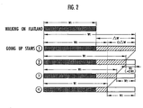
- FIG. 2 is a schematic explanatory view of walking assistance by the walking assisting apparatus
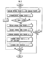
- FIG. 3 is a flowchart showing a function of the walking assisting apparatus
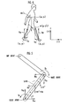
- FIG. 4 is a schematic explanatory view of floor reaction force measurement of a walker's foot
- FIG. 5 is a schematic explanatory view of torque measurement around a walker's joint
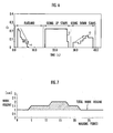
- FIG. 6 is an explanatory view of an experiment result of the walking assistance by the walking assisting apparatus
- FIGS. 7 and 8 are explanatory views of a simulation result of the walking assistance by the walking assisting apparatus.
- the torque imparting system shown in FIG. 1 includes: a first actuator (external torque imparting means) 1, attached to a walker's waist, for imparting an external torque around a hip joint; second actuators (the same as above) 2, attached to walker's knees, for imparting the external torque around a knee joint; a control unit 3 for controlling operations and the like of the respective actuators 1, 2; and a battery 4 such as an Ni-Zn battery for supplying power to the respective actuators 1, 2.
- the control unit 3 and battery 4 are housed in a backpack 5 carried on a walker's back.
- the first actuator 1 applies the external torque around the hip joint via a bellyband b and a thigh pad c attached to a walker.
- the second actuator 2 imparts the external torque around the knee joint via the thigh pad c and shin guard d attached to the walker. It is to be noted that the walker's waist, thigh, and shin correspond to a "connected body".
- the present walking assisting apparatus is attached to the walker's back, and includes a gyro sensor g for measuring an angular velocity with respect to a vertical direction of the upper part of the body, and a G sensor g' for measuring acceleration in a horizontal direction.
- the apparatus is further attached to the walker's waist, and includes the gyro sensor g for measuring the angular velocity with respect to the vertical direction of the waist, and the G sensor g' for measuring the acceleration in the horizontal and vertical direction.
- the apparatus includes angle sensors a which are attached to the walker's waist to measure rotation angles of left/right thighs around the hip joints with respect to the waist and which are attached to the knees to measure the rotation angles of the shins with respect to the thighs.
- the control unit 3 includes a first measuring means 6, second measuring means 7, reference work volume determining means 8, first coefficient determining means 9, external torque determining means 10, and memory means 11.
- the control unit 3 is constituted from a combination of CPU, signal input/output circuit, memory, and the like so as to be capable of fulfilling various functions described later.
- the first measuring means 6 measures an internal torque T 1 of a leg body around knee and hip joints, and an internal work volume w 1 which is time integration of an absolute value of a product of the internal torque T 1 and an internal angular velocity ⁇ 1 on the basis of measured values of the respective sensors g, g', a.
- the second measuring means 7 measures an external work volume w 2 which is the time integration of the absolute value of the product of an external torque T 2 around the knee and hip joints and an external angular velocity ⁇ 2 on the basis of torque values of the respective actuators 1, 2 and the measured values of the angle sensors a.
- the reference work volume determining means 8 determines a reference work volume w 0 on the basis of the internal work volume w 1 of the leg body measured by the first measuring means 6.
- the first coefficient determining means 9 determines a ratio of the external work volume w 2 to the internal work volume w 1 in a case where a deviation of the internal work volume w 1 from the reference work volume w 0 determined by the reference work volume determining means 8 becomes 0 as a desired value c TG , determines a ratio of the external work volume w 2 to the internal work volume w 1 as a first coefficient c 1 , and successively determines the first coefficient c 1 so that the coefficient converges to the desired value with an elapse of time.
- the external torque determining means 10 calculates a product of the internal torque T 1 measured by the first measuring means 6 and the first coefficient c 1 determined by the first coefficient determining means 9 to determine the external torque T 2 imparted around the hip and knee joints through the actuators 1, 2.
- the memory means 11 is constituted of nonvolatile memories such as ROM, volatile memories such as RAM, and the like, and stores a second coefficient c 2 for use in determining the reference work volume w 0 as described later, a data table for use in measuring floor reaction forces onto the walker's left/right feet, and the like.
- the internal work volume w 1 around the knee joint at the time when the walker walks on a flatland in a non-load state is shown in blackened portions.
- the "internal work volume w 1 in the non-load state” includes: an internal work volume measured by a three-dimensional motion analysis apparatus and the like in a state in which the walking assisting apparatus is not attached to the walker; and also an internal work volume determined by decreasing the internal work volume measured by the angle sensors a in a state in which the walking assisting apparatus is attached to the walker in consideration of a weight or friction of the apparatus.
- the external torque T 2 is imparted to the leg body so as to assist the walker in walking up the stairs.
- the external torque T 2 is successively determined on the basis of the internal torque T 1 so that the internal work volume w 1 converges to this reference work volume w 0 .
- the external work volume w 2 gradually increases every shift to 2 ⁇ from 1 ⁇ , 3 ⁇ from 2 ⁇ , 4 ⁇ from 3 ⁇ in FIG. 2, and accordingly the internal work volume w 1 gradually decreases to converge to the reference work volume w 0 .
- the floor reaction forces onto the walker's left/right leg bodies are measured using a model shown in FIG. 4.
- Floor reaction forces (F Lx , F Ly ), (F Rx , F Ry ) act on the left and right leg bodies of the walker having a mass m shown in FIG. 4.
- Walker's body gravity center coordinate, left foot joint coordinate, and right foot joint coordinate are (x G , y G ), (x L , y L ), (x R , y R ), respectively.
- the following relational equations (1a) to (1d) are obtained.
- F Ry +F Ly m(g+y G ") (g: gravity acceleration)
- the walker's mass m is measured beforehand.
- the body gravity center coordinate (x G , y G ), left/right foot joint coordinates (x L , y L ), (x R , y R ), and accelerations (x G ", y G ") of the body gravity center coordinate are measured on the basis of the measured values of physical measurement of the walker in advance, gyro sensor g and G sensor g' attached to the walker's waist and the like, and angle sensors a attached to the hip and knee joints.
- the left/right foot joint coordinates (x L , y L ), (x R , y R ), and the like are measured on the basis of a data table in which correspondences with the angles of the hip or knee joints, the lengths of the thigh and shin, and the like stored in the memory means 11 are specified. Moreover, when these measured values are assigned to the above relational equations, the first measuring means 6 measures the floor reaction forces (F Lx , F Ly ), (F Rx , F Ry ).
- a total torque around the knee and hip joints is measured in accordance with an inverse kinetic model using a model shown in FIG. 5 based on the measured floor reaction force.
- a floor reaction force F ax , F ay
- a reaction force F bx , F by
- a force mx", m(y"+g) accompanied by the acceleration acts on the center of gravity of the shin with the mass m.
- the floor reaction force (F ax , F ay ) is measured by the above-described method. Moreover, an acceleration (x", y") of the center of gravity of the shin, angle ⁇ of the shin with respect to the floor, and angular acceleration ⁇ " are measured on the basis of the measured values of the physical measurement of the walker in advance and the gyro sensor g, G sensor g', and angle sensors a attached to the walker. Furthermore, the moment of inertia of the shin I, and the distances a, b between the foot and knee joints and the center of gravity of the shin, respectively, are measured on the basis of the physical measurement of the walker in advance.
- the torque T a around the foot joint is measured by the first measuring means 6 in accordance with the data table stored in the memory means 11 on the basis of the floor reaction force (F ax , F ay ). Moreover, when these measured values are assigned to the above relational equations (2a) to (2c), the torque T b around the knee joint is measured. Similarly, the above relational equations (2a) to (2c) are also used to measure the torque around the hip joint.
- the external torque T 2(i) is determined by the external torque determining means 10, and imparted to the walker's leg body through the first and second actuators 1, 2 (FIG. 3 s2).
- the external torque T 2(i) is determined by the product of the internal torque T 1(i) successively measured by the first measuring means 6 and a first coefficient c 1(i) determined by the first coefficient determining means 9 every walking period. That is, the first coefficient c 1(i) determines the percentage of the external torque T 2(i) with respect to the internal torque T 1(i) .
- a method of determining the first coefficient c 1(i) will be described later.
- the control unit 3 judges whether or not an i-th period has been elapsed (FIG. 3 s3). Specifically, a period in which the floor reaction force of the right foot measured by the first control means 6 turns to 0 from a finite value, again turns to the finite value, and thereafter turns to 0 is judged as an elapse of a walking period.
- the internal torque T 1(i) , external torque T 2(i) , and angular velocity ⁇ (i) around each joint are physical amounts which are time functions fluctuating every moment even in the i-th period.
- the reference work volume determining means 8 determines a reference work volume w 0(i+1) of an i+1st period in accordance with the next equation (5) (FIG. 3 s6).
- a fluctuation of a total work volume w 1(i) +w 2(i) which is a sum of the internal work volume w 1(i) and the external work volume w 2(i) with respect to an internal work volume w 1(0) at the time of the flatland walking measured beforehand is measured.
- a reference work volume w 0(i+1) is determined by subtracting a product of the second coefficient c 2 (0 ⁇ c 2 ⁇ 1) stored in the memory means 11 and a fluctuation ⁇ w i from the total work volume w 1(i) +w 2(i) .
- the second coefficient c2 determines a ratio of a fluctuation compensated by an imparted external torque T 2(i+1) in this fluctuation ⁇ w i .
- an external torque T 2(i+1) is determined so as to compensate for all the fluctuations ⁇ w i , that is, so that the walking can be continued by the internal work volume w 1(0) in a flatland walking state regardless of the fluctuation of a walking state.
- the external torque T 2(i+1) is determined so as to compensate for the half of the fluctuation ⁇ w i .
- the second coefficient c 2 may also be set/updated in an operation panel (not shown) and the like.
- the first coefficient determining means 9 determines a desired value c TG(i+1) of the first coefficient in accordance with the following equation (6) (FIG. 3 s7).
- c TG(i+1) c 2 ⁇ w i / ⁇ w 1(0) +(1-c 2 ) ⁇ w i ⁇
- the first coefficient determining means uses a gain coefficient G (0 ⁇ G s 1) stored in the memory means 11 to determine the first coefficient c 1(i+1) in accordance with the following equation (7).
- the size of the gain coefficient G determines a speed at which the internal work volume w 1(i+1) converges to the reference work volume w 0(i+1) . That is, the external torque T 2(i) is increased so that the internal work volume w 1(i) quickly converges to the reference work volume w 0(i) with an increase of the gain coefficient G.
- the gain coefficient G may also be set/updated in the operation panel (not shown).
- c 1(i+1) w 2(i) /w 1(i) +G(c TG(i+1) -w 2(i) /w 1(i) )
- the first coefficient c 1(i) of the i-th period is updated to c 1(i+1) (FIG. 3 s11).
- the first measuring means 6 measures the internal torque T 1(i+1) (FIG. 3 s1).
- the external torque determining means 10 determines the external torque T 2(i+1) as the product of the first coefficient c i(n+1) and the internal torque T 1(i+1) as described above as in the following equation (8) (FIG. 3 s2).
- T 2(i+1) +c 1(i+1) T 1(i+1)
- the external torque T 2(i+1) determined by the external torque determining means 10 is imparted to the walker's leg body through the first and second actuators (FIG. 3 s2).
- FIG. 6 shows the fluctuation of the first coefficient c 1 in a case in which the walker starts walking on the flatland, goes up the stairs, and goes down the stairs.
- the first coefficient c 1 governs the percentage of the internal torque T 1 determined/imparted as the external torque T 2
- the fluctuation of the external torque T 2 can indirectly be grasped through the fluctuation thereof.
- an upper limit of the first coefficient c 1 is set to 0.25
- that of the second coefficient c 2 is set to 0.25.
- the first coefficient c 1 starting from 0 reaches the upper limit of 0.25, and thereafter gradually decreases to reach 0 (see downward arrows in the drawing). This indicates that immediately after the start of the walking on the flatland, a large external torque is imparted to the knee joint to assist the walker in walking, thereafter the external torque gradually decreases, and the walker walks on one's own.
- the first coefficient c 1 reaches the upper limit of 0.25 from 0, and is thereafter maintained at the upper limit substantially over the whole time. This indicates that while the walker goes up the stairs, the walker is assisted in walking by a steadily imparted large external torque to the knee joint thereof.
- the first coefficient c 1 rises to about 0.1 from 0, slightly decreases, and gradually increases to about 0.15 (see upward arrows in the drawing). This indicates that a suitable external torque in going down the stairs, which is smaller than that in going up the stairs, is imparted to the knee joint to assist the walker in walking.
- FIGS. 7 and 8 a result of simulation on the fluctuation of the external work volume w 2 imparted to the walker in relation to the fluctuation of the walking conditions will be described with reference to FIGS. 7 and 8.
- the ordinate indicates the total work volume required for the walking
- the abscissa indicates a walking period of the walker.
- the work volume is standardized by the total work volume (dotted line) at the time of the flatland walking.
- FIG. 7 the fluctuation of the total work volume on the basis of the volume at the time of the flatland walking is shown by slanted lines
- FIG. 8 the fluctuation of the external work volume is shown by the slanted lines.
- the total work volume increases to 1.0 in first to fourth periods, to 1.5 from 1.0 in a fifth period, to 1.5 in sixth to eleventh periods, and to 2.0 from 1.5 in a twelfth period.
- the volume is maintained at 2.0 in a thirteenth to seventeenth periods, decreases to 1.5 from 2.0 in an eighteenth period, is maintained at 1.5 in a nineteenth to 21st periods, decreases to 1.0 from 1.5 in a 22nd period, and is maintained at 1.0 in and after a 23rd period.
- the increase of the total work volume follows, for example, a shift to the walking up the slope or stairs from the walking on the flatland
- the decrease of the total work volume follows, for example, the shift to the walking on the flatland from the walking up the slope or stairs.
- FIGS. 8(a), 8(b), 8(c), and 8(d) The simulation results of the fluctuations of the internal and external work volumes are shown in FIGS. 8(a), 8(b), 8(c), and 8(d) in a case where combinations of the second coefficient c 2 and the gain coefficient G are assumed to be (1.0, 0.6), (0.5, 0.6), (1.0, 1.0), and (0.5, 1.0), respectively.
- FIGS. 8(a) and 8(c), or FIGS. 8(b) and 8(d) it is apparent that when the gain coefficient G is large, the external torque imparted around the joint and further the external work volume (shaded portions of FIGS. 8(a) to 8(d)) quickly fluctuate in accordance with the fluctuation (shaded portions of FIG. 7). It is also apparent that when the gain coefficient G is small, the external work volume imparted around the joint (shaded portions of FIGS. 8(a) to 8(d)) moderately fluctuates in accordance with the fluctuation (shaded portions of FIG. 7). That is, as described above with reference to FIG.
- the external work volume (whitened portion) w 2 gradually increases at the time of the walking-up of the stairs.
- a speed of the shift to FIG. 2 2 ⁇ from 1 ⁇ , 3 ⁇ from 2 ⁇ , 4 ⁇ from 3 ⁇ increases.
- the external torque T 2 around the joint is imparted to the leg body so that the internal work volume w 1 around the walker's joint of the leg body agrees with the reference work volume w 0 . Therefore, when the walker shifts to the stairs walking from the flatland walking and the like, the walking conditions fluctuate, and the work volume of the leg body required for the walking exceeds the reference work volume w 0 , the external torque T 2 is imparted to the leg bodies or the like in such a manner as to assist the surplus. Moreover, regardless of the fluctuation of the walking conditions, the walking is possible by the internal torque T 1 exerted in accordance with the reference work volume w 0 in the leg body.
- the external torque T 2 imparted to the leg body is determined on the basis of the first coefficient c 1 and further the external work volume w 2 imparted to the leg body (see the above equations (6) to (8)), and the reference work volume w 0 which is a reference in the determination is determined on the basis of the internal work volume w 1 of the leg body (see the above equation (5)). Therefore, the suitable external torque T 2 can be imparted to the leg body in accordance with a balance between the internal work volume wl and the external work volume w 2 of the leg body.
- the convergence speed of the first coefficient c 1 to the desired value c TG can be increased.
- the external torque T 2 can be imparted to the leg body so as to quickly eliminate the surplus (see FIGS. 8(c), 8(d)).
- the gain coefficient G is reduced, the convergence speed of the first coefficient c 1 to the desired value c TG can be reduced.
- the external torque T 2 can be imparted to the leg body so as to slowly eliminate the surplus (see FIGS. 8(a), 8(b)).
- the fluctuation to be compensated by the external torque T 2 is determined by the size of the second coefficient c 2 . That is, when the second coefficient c 2 is set to be large, the ratio of the fluctuation to be compensated by the external torque T 2 in the fluctuations can be increased (see FIGS. 8(a), 8(c)). On the other hand, when the second coefficient c 2 is set to be small, the ratio of the fluctuation to be compensated by the external torque T 2 in the fluctuations can be reduced (see FIGS. 8(b), 8(d)).
- the external torque around the hip and knee joints is imparted to the walker's leg body in the present embodiment, but the external torque around the foot joint may also be imparted to the leg body in another embodiment, and an external torque of an arm around a hand root joint, elbow joint, or shoulder joint may also be imparted.
- the "connected body" constituting an object to which the external torque is to be imparted includes the walker's waist and thigh connected through the hip joints, and the thigh and shin connected through the knee joints, but in the other embodiment, the "connected body” may also be the shin and foot connected through the foot joints.
- the external torque around the joint has been imparted to the leg body so as to assist the motion of a person, but in the other embodiment, the external torque around the joint may also be imparted to the leg body so as to assist the motions of animals such as cats and dogs.
- the torque imparting system of the present invention can be applied not only to human medical care, welfare, and sport fields or the like but also to a field of veterinary medicine.
- the external torque is imparted to the left/right leg bodies, but in the other embodiment, the external torque may be applied only to either one of left or right leg body.
- the external torque T 2 has been imparted so as to assist the walker in walking, but in the other embodiment, the external torque T 2 may also be imparted in a direction reverse to a direction in which the walker is to move.
- the first coefficient determining means 9 determines the first coefficient c 1 to be negative
- a symbol of the external torque T 2 differs from that of the internal torque T 1 (see the above equation (8)).
- the torque imparting system of the present invention is used as a training apparatus for strengthening athletes' muscle forces or the like.
- control unit 3 is housed in the backpack 5 of the walking assisting apparatus, but in the other embodiment, the control unit 3 is separated from the walking assisting apparatus.
- the internal torque T 1 in the control unit 3 may be measured, the external torque T 2 may be determined, or operation instructions of the first and second actuators 1, 2 may also be given.
- the first coefficient determining means 9 may determine the lower limit of the first coefficient c 1 as 0, when the total work volume as the sum of the internal work volume w 1 measured by the first measuring means 6 and the external work volume w 2 measured by the second measuring means 7 is equal to or less than the reference work volume w 0 determined by the reference work volume determining means 8. Accordingly, when the total work volume w 1 +w 2 of the leg body decreases to be below the reference work volume w 0 , a situation can be prevented in which the first coefficient c 1 is determined to be negative and the negative external torque T 2 is imparted to the leg body.
- the first coefficient determining means 9 may also determine the upper limit of the first coefficient c 1 , when the total work volume w 1 +w 2 of the leg body is equal to or more than a predetermined volume (0, 1.5w 0 , 2.5w 0 , .. and the like) equal to or more than the reference work volume w 0 determined by the reference work volume determining means 8. Accordingly, when the total work volume w 1 +w 2 of the leg body increases to largely exceed the reference work volume w 0 , a situation can be prevented in which the first coefficient c 1 is determined to be excessively large and the excessively large external torque T 2 is imparted to the leg body.
- the product of the internal torque T 1 and angular velocity ⁇ 1 , and the product of the external torque T 2 and angular velocity ⁇ 2 are time-integrated over the walking period of the walker, and the internal work volume w 1 and external work volume w 2 are measured based on the integral time (see the above equations (3), (4), and s3 to s5 of FIG. 3), but in the other embodiment, the integral time may also be a unit time, and may also be a different time such as a time required for the walker to move by a unit distance.
- the internal torque T 1 and internal work volume w 1 of the knee and hip joints have been measured on the basis of the floor reaction force onto the leg body in accordance with the inverse kinetic model (see FIG. 5, equations (2a) to (2c), and in the other embodiment, the internal torque T 1 and internal work volume w 1 of each joint may also be measured by a three-dimensional motion analysis apparatus. That is, the motion of the leg body is photographed from xyz directions, an image indicating an angle of each joint bent at an angular velocity ⁇ 1 is analyzed, and the internal torque T 1 or the internal work volume w 1 of each joint may be measured on the basis of this analysis result.
- the floor reaction force onto the walker's leg body has been measured on the basis of the measured values of the angle sensors a and the like (see FIG. 4, equations (1a) to (1d)), but in the other embodiment, a floor reaction force sensor is disposed on walker's shoes, and accordingly the floor reaction force may directly be measured.
- the internal torque T 1 and (internal) angular velocity ⁇ around the joint are measured, and the absolute value of the product of the both is time-integrated to measure the internal work volume w 1 around the joint (see the equation (3)).
- muscle shrinkage force and speed associated with the walker's joint are measured, and the internal work volume w 1 around the joint may also be measured on the basis of the product of the both.
- the angle of left/right thighs, shin and the like to the vertical direction, or the movement distances of the feet are measured, a correspondence data table of the measured value and the internal work volume w 1 is stored/held by the memory means 11, and the measured value and data table may be used to measure the internal work volume w 1 .
- the external torque T 2 and (external) angular velocity ⁇ around the joint are measured, the absolute value of the product of the both is time-integrated, and accordingly the external work volume w 2 around the joint is measured (see the equation (4)).
- power consumptions of the respective actuators 1, 2 are measured, and the external work volume w 2 may also be measured on the basis of the power consumption.
- the actuators 1, 2 are of a hydraulic type, the fluctuation of a hydraulic pressure is measured, then the external work volume w 2 may also be measured on the basis of the integral time of the hydraulic pressure fluctuation.
- the first measuring means 6 and second measuring means 7 measure integrated portions w 1(i) + , w 2(i) + with the positive product of the internal and external work volumes w 1(i) , w 2(i) in accordance with the following equations (9) to (12), and integrated portions w 1(i) - , w 2(i) - with the negative product thereof in a divided manner.
- the first coefficient determining means 9 determines different first coefficients c 1(i+1) + , c 1(i+1) - on the basis of w 1(i) + and w 2(i) + , further w 1(i) - and w 2(i) - (see the equation (7)).
- the external torque determining means 10 determines the external torque T 2(i+1) on the basis of the first coefficient c 1(i+1) + determined in accordance with the "positive" product in the i-th period, when the product of the internal torque T 1(i+1) and the angular velocity ⁇ (i+1) is "positive” in an i+1st period (see the equation (8)).
- the external torque T 2(i+1) is determined on the basis of the first coefficient c 1(i+1) - determined in accordance with the "negative” product in the i-th period, when the product is "negative” (the same as above).
- the existing external torque T 2 can be determined/imparted on the basis of the first coefficient c 1 determined beforehand in accordance with the past walking conditions.
- the first coefficient c 1 and further the external torque T 2 have been determined depending on whether the product of the internal torque T 1 and angular velocity ⁇ is positive/negative, but in still another embodiment, the first coefficient c 1 may also be determined in accordance with three or more segments of the product. For example, the first coefficient c 1 may also be determined, when the product is less than -2, not less than -2 and less than +1, or +1 or more by an arbitrary unit.
Landscapes
- Health & Medical Sciences (AREA)
- Epidemiology (AREA)
- Pain & Pain Management (AREA)
- Physical Education & Sports Medicine (AREA)
- Rehabilitation Therapy (AREA)
- Life Sciences & Earth Sciences (AREA)
- Animal Behavior & Ethology (AREA)
- General Health & Medical Sciences (AREA)
- Public Health (AREA)
- Veterinary Medicine (AREA)
- Engineering & Computer Science (AREA)
- Robotics (AREA)
- Mechanical Engineering (AREA)
- Rehabilitation Tools (AREA)
- Manipulator (AREA)
Abstract
Description


Claims (11)
- A system for imparting an external torque around a joint with respect to a connected body relatively and rotatably connected through the joint, comprising:a first measuring means for measuring an internal work volume around the joint generated from the connected body;a second measuring means for measuring an external work volume around the joint imparted to the connected body;a reference work volume determining means for determining a reference work volume on the basis of the internal work volume of the connected body measured by the first measuring means;an external torque determining means for determining an external torque imparted to the connected body in such a manner as to reduce a difference between the internal work volume of the connected body measured by the first measuring means and the reference work volume determined by the reference work volume determining means on the basis of the external work volume measured by the second measuring means; andan external torque imparting means for imparting the external torque determined by the external torque determining means to the connected body.
- The torque imparting system according to claim 1, wherein the connected body is a walker's leg body including a hip joint, knee joint, and foot joint.
- The torque imparting system according to claim 1 or 2, further comprising:a first coefficient determining means for regarding a ratio of the external work volume imparted to the connected body with respect to the internal work volume of the connected body as a desired value in a case in which a difference from the reference work volume determined by the reference work volume determining means is 0 and for successively determining a first coefficient so that the coefficient converges to the desired value with an elapse of time, wherein the first measuring means measures the internal torque around the joint of the connected body,the external torque determining means calculates a product of the internal torque of the connected body measured by the first measuring means and the first coefficient determined by the first coefficient determining means, andthe calculation result is determined as the external torque imparted to the connected body.
- The torque imparting system according to claim 3, wherein the first coefficient determining means determines an upper limit or a lower limit of the first coefficient on the basis of the internal work volume measured by the first measuring means or the external work volume measured by the second measuring means.
- The torque imparting system according to claim 3, wherein the first coefficient determining means determines the lower limit of the first coefficient as 0, when a total work volume that is a sum of the internal work volume determined by the first measuring means and the external work volume measured by the second measuring means is not more than the reference work volume determined by the reference work volume determining means.
- The torque imparting system according to claim 3, wherein the first coefficient determining means determines the upper limit of the first coefficient, when the total work volume that is the sum of the internal work volume determined by the first measuring means and the external work volume measured by the second measuring means is not less than a predetermined volume not less than the reference work volume determined by the reference work volume determining means.
- The torque imparting system according to claim 3, wherein the first measuring means measures a product of the internal torque of the connected body around the joint and an angular velocity thereof,
the first coefficient determining means segments and determines the first coefficient in accordance with a segment of the product measured by the first measuring means, and
the external torque determining means uses the first coefficient previously determined on the basis of the internal work volume in accordance with the past segment of the product by the first coefficient determining means to determine the external torque, when the segment of the product measured by the first measuring means agrees with the past segment of the product previously measured by the first measuring means. - The torque imparting system according to claim 7, wherein the first coefficient determining means segments and determines the first coefficient depending on whether the product of the internal torque of the connected body around the joint measured by the first measuring means and the angular velocity is positive or negative.
- The torque imparting system according to claim 1, 2, 3, 4, 5, 6, 7, or 8, wherein the reference work volume determining means calculates the total work volume which is the sum of the internal work volume measured by the first measuring means and the external work volume measured by the second measuring means,
a product of a difference between the total work volume and the internal work volume of the connected body in a non-load state measured by the first measuring means, and a second coefficient concerning the external torque assuming that the difference between the internal work volume of the connected body and the reference work volume is 0 is calculated, and
a difference between the total work volume and the product is calculated to determine the calculation result as the reference work volume. - The torque imparting system according to claim 1, 2, 3, 4, 5, 6, 7, 8, or 9, wherein the first and second measuring means regard a motion period of the connected body as an integration time to measure the internal and external work volumes.
- The torque imparting system according to claim 1, 2, 3, 4, 5, 6, 7, 8, 9, or 10, wherein the first measuring means measures a reaction force which works on one joint of the connected body, measures a total torque of the internal torque and external torque of the connected body around each joint in accordance with an inverse kinetic model on the basis of the measured reaction force, and calculates a difference from the external torque measured by the second measuring means from the measured total torque to measure the internal torque of the connected body around each joint.
Applications Claiming Priority (7)
| Application Number | Priority Date | Filing Date | Title |
|---|---|---|---|
| US30081501P | 2001-06-27 | 2001-06-27 | |
| US300815P | 2001-06-27 | ||
| JP2001200416 | 2001-07-02 | ||
| JP2001200416 | 2001-07-02 | ||
| JP2001236336 | 2001-08-03 | ||
| JP2001236336A JP4611580B2 (en) | 2001-06-27 | 2001-08-03 | Torque application system |
| PCT/JP2002/006468 WO2003002054A1 (en) | 2001-06-27 | 2002-06-27 | Torque imparting system |
Publications (3)
| Publication Number | Publication Date |
|---|---|
| EP1410780A1 true EP1410780A1 (en) | 2004-04-21 |
| EP1410780A4 EP1410780A4 (en) | 2006-07-19 |
| EP1410780B1 EP1410780B1 (en) | 2010-06-30 |
Family
ID=27347066
Family Applications (1)
| Application Number | Title | Priority Date | Filing Date |
|---|---|---|---|
| EP02736184A Expired - Lifetime EP1410780B1 (en) | 2001-06-27 | 2002-06-27 | Torque imparting system |
Country Status (8)
| Country | Link |
|---|---|
| US (1) | US7713217B2 (en) |
| EP (1) | EP1410780B1 (en) |
| JP (1) | JP4611580B2 (en) |
| KR (1) | KR100849655B1 (en) |
| CN (1) | CN100393295C (en) |
| CA (1) | CA2451836C (en) |
| DE (1) | DE60236869D1 (en) |
| WO (1) | WO2003002054A1 (en) |
Cited By (28)
| Publication number | Priority date | Publication date | Assignee | Title |
|---|---|---|---|---|
| EP1848381A2 (en) * | 2005-02-16 | 2007-10-31 | OSSUR North America, Inc. | System and method of synchronizing and communicating with mechatronic devices |
| EP1864278A4 (en) * | 2005-04-01 | 2008-05-07 | Honda Motor Co Ltd | An exoskeleton controller for a human-exoskeleton system |
| EP1868546A4 (en) * | 2005-04-12 | 2008-05-21 | Honda Motor Co Ltd | Active control of an ankle-foot orthosis |
| EP1583497A4 (en) * | 2002-11-25 | 2008-10-01 | Tibion Corp | DEVICE AND METHOD FOR ACTIVE MUSCLE AID |
| RU2364385C2 (en) * | 2005-01-26 | 2009-08-20 | Юниверсити Оф Цукуба | Portable motion-activity accessory, and control program |
| EP2184046A4 (en) * | 2007-10-19 | 2011-04-13 | Honda Motor Co Ltd | MOTION ASSISTING DEVICE |
| US8274244B2 (en) | 2008-08-14 | 2012-09-25 | Tibion Corporation | Actuator system and method for extending a joint |
| US8353854B2 (en) | 2007-02-14 | 2013-01-15 | Tibion Corporation | Method and devices for moving a body joint |
| US8639455B2 (en) | 2009-02-09 | 2014-01-28 | Alterg, Inc. | Foot pad device and method of obtaining weight data |
| EP2085066A4 (en) * | 2007-10-15 | 2014-04-09 | Honda Motor Co Ltd | Motion assisting device |
| US8771210B2 (en) | 2008-02-08 | 2014-07-08 | Alterg, Inc. | Multi-fit orthotic and mobility assistance apparatus |
| US9649206B2 (en) | 2002-08-22 | 2017-05-16 | Victhom Laboratory Inc. | Control device and system for controlling an actuated prosthesis |
| US9707104B2 (en) | 2013-03-14 | 2017-07-18 | össur hf | Prosthetic ankle and method of controlling same based on adaptation to speed |
| US9808357B2 (en) | 2007-01-19 | 2017-11-07 | Victhom Laboratory Inc. | Reactive layer control system for prosthetic and orthotic devices |
| US9889058B2 (en) | 2013-03-15 | 2018-02-13 | Alterg, Inc. | Orthotic device drive system and method |
| US9895240B2 (en) | 2012-03-29 | 2018-02-20 | Ösur hf | Powered prosthetic hip joint |
| US10179078B2 (en) | 2008-06-05 | 2019-01-15 | Alterg, Inc. | Therapeutic method and device for rehabilitation |
| US10195057B2 (en) | 2004-02-12 | 2019-02-05 | össur hf. | Transfemoral prosthetic systems and methods for operating the same |
| US10251762B2 (en) | 2011-05-03 | 2019-04-09 | Victhom Laboratory Inc. | Impedance simulating motion controller for orthotic and prosthetic applications |
| US10369019B2 (en) | 2013-02-26 | 2019-08-06 | Ossur Hf | Prosthetic foot with enhanced stability and elastic energy return |
| US10390974B2 (en) | 2014-04-11 | 2019-08-27 | össur hf. | Prosthetic foot with removable flexible members |
| US10543109B2 (en) | 2011-11-11 | 2020-01-28 | Össur Iceland Ehf | Prosthetic device and method with compliant linking member and actuating linking member |
| US10575970B2 (en) | 2011-11-11 | 2020-03-03 | Össur Iceland Ehf | Robotic device and method of using a parallel mechanism |
| US11007072B2 (en) | 2007-01-05 | 2021-05-18 | Victhom Laboratory Inc. | Leg orthotic device |
| EP2873407B1 (en) * | 2013-11-07 | 2022-01-05 | Samsung Electronics Co., Ltd. | Walking assistance robot and method of controlling the walking assistance robot |
| EP3820410A4 (en) * | 2018-07-10 | 2022-04-06 | Dephy, Inc. | WEARABLE JOINT AUGMENTATION SYSTEM |
| US12370116B2 (en) | 2018-03-27 | 2025-07-29 | Dephy, Inc. | Dynamic mounting mechanism for an exoskeleton |
| US12575950B2 (en) | 2019-09-18 | 2026-03-17 | Össur Iceland Ehf | Methods and systems for controlling a prosthetic or orthotic device |
Families Citing this family (100)
| Publication number | Priority date | Publication date | Assignee | Title |
|---|---|---|---|---|
| US7251593B2 (en) * | 2001-10-29 | 2007-07-31 | Honda Giken Kogyo Kabushiki Kaisha | Simulation system, method and computer-readable medium for human augmentation devices |
| US7684896B2 (en) * | 2001-06-29 | 2010-03-23 | Honda Motor Co., Ltd. | System and method of estimating joint loads using an approach of closed form dynamics |
| US7469166B2 (en) * | 2001-06-29 | 2008-12-23 | Honda Motor Co., Ltd. | System and method of predicting novel motion in a serial chain system |
| US7623944B2 (en) * | 2001-06-29 | 2009-11-24 | Honda Motor Co., Ltd. | System and method of estimating joint loads in a three-dimensional system |
| US7390309B2 (en) * | 2002-09-23 | 2008-06-24 | Honda Motor Co., Ltd. | Human assist system using gravity compensation control system and method using multiple feasibility parameters |
| US7650204B2 (en) | 2001-06-29 | 2010-01-19 | Honda Motor Co., Ltd. | Active control of an ankle-foot orthosis |
| US7135003B2 (en) | 2001-06-29 | 2006-11-14 | Honda Giken Kogyo Kabushiki Kaisha | Feedback estimation of joint forces and joint moments |
| US7217247B2 (en) | 2002-09-23 | 2007-05-15 | Honda Giken Kogyo Kabushiki Kaisha | Gravity compensation method in a human assist system and a human assist system with gravity compensation control |
| JP3930399B2 (en) | 2002-08-21 | 2007-06-13 | 本田技研工業株式会社 | Walking assist device |
| US7736394B2 (en) | 2002-08-22 | 2010-06-15 | Victhom Human Bionics Inc. | Actuated prosthesis for amputees |
| US7402142B2 (en) | 2002-09-23 | 2008-07-22 | Honda Giken Kogyo Kabushiki Kaisha | Method and processor for obtaining moments and torques in a biped walking system |
| US7066896B1 (en) * | 2002-11-12 | 2006-06-27 | Kiselik Daniel R | Interactive apparatus and method for developing ability in the neuromuscular system |
| JP4178186B2 (en) | 2003-08-21 | 2008-11-12 | 国立大学法人 筑波大学 | Wearable motion assist device, control method for wearable motion assist device, and control program |
| US7628766B1 (en) * | 2003-10-29 | 2009-12-08 | The Regents Of The University Of California | Lower extremity enhancer |
| US7815689B2 (en) | 2003-11-18 | 2010-10-19 | Victhom Human Bionics Inc. | Instrumented prosthetic foot |
| US7637959B2 (en) | 2004-02-12 | 2009-12-29 | össur hf | Systems and methods for adjusting the angle of a prosthetic ankle based on a measured surface angle |
| JP4178185B2 (en) * | 2004-02-17 | 2008-11-12 | 国立大学法人 筑波大学 | Wearable motion assist device, drive source control method and program in wearable motion assist device |
| JP4503311B2 (en) * | 2004-02-25 | 2010-07-14 | 本田技研工業株式会社 | Method for controlling generated torque of leg exercise assistive device |
| JP4200492B2 (en) | 2004-03-11 | 2008-12-24 | 国立大学法人 筑波大学 | Wearable motion assist device |
| US7429253B2 (en) * | 2004-09-21 | 2008-09-30 | Honda Motor Co., Ltd. | Walking assistance system |
| JP4541867B2 (en) * | 2004-12-16 | 2010-09-08 | 本田技研工業株式会社 | External force control method, external force control system, and external force control program |
| CA2592042C (en) | 2004-12-22 | 2014-12-16 | Oessur Hf | Systems and methods for processing limb motion |
| JP4344314B2 (en) * | 2004-12-28 | 2009-10-14 | 本田技研工業株式会社 | Weight relief assist device and weight relief assist program |
| WO2006092872A1 (en) * | 2005-02-28 | 2006-09-08 | National University Corporation NARA Institute of Science and Technology | Driving force computing device, driving force computing method, muscle force assisting device, program, and computer-readable recording medium |
| DE602006014813D1 (en) * | 2005-03-31 | 2010-07-22 | Thk Co Ltd | SERVO CONTROL, SERVO CONTROL AND NEW POSITIONING |
| US8057410B2 (en) * | 2005-04-13 | 2011-11-15 | The Regents Of The University Of California | Semi-powered lower extremity exoskeleton |
| CN101184463B (en) * | 2005-05-31 | 2012-09-05 | 本田技研工业株式会社 | Control device and control method of walking assist device |
| US8082062B2 (en) * | 2005-06-10 | 2011-12-20 | Honda Motor Co., Ltd. | Regenerative actuation in motion control |
| JP4417300B2 (en) * | 2005-07-13 | 2010-02-17 | 本田技研工業株式会社 | Walking assist device |
| JP3950149B2 (en) * | 2005-09-02 | 2007-07-25 | 本田技研工業株式会社 | Exercise assistance device |
| US7632239B2 (en) * | 2005-11-16 | 2009-12-15 | Bioness Neuromodulation Ltd. | Sensor device for gait enhancement |
| US7862524B2 (en) * | 2006-03-23 | 2011-01-04 | Carignan Craig R | Portable arm exoskeleton for shoulder rehabilitation |
| JP2009533101A (en) * | 2006-04-10 | 2009-09-17 | エルンスト,アルネボルグ | Portable balancing prosthesis |
| WO2007125534A2 (en) | 2006-05-01 | 2007-11-08 | N.E.S.S. Neuromuscular Electrical Stimulation Systems Ltd | Improved functional electrical stimulation systems |
| JP4712620B2 (en) * | 2006-06-12 | 2011-06-29 | 本田技研工業株式会社 | Control device for walking aids |
| JP4666644B2 (en) * | 2006-07-12 | 2011-04-06 | 本田技研工業株式会社 | Control device for walking aids |
| US20080119763A1 (en) * | 2006-11-21 | 2008-05-22 | Jay Wiener | Acquisition processing and reporting physical exercise data |
| KR100810004B1 (en) * | 2007-02-28 | 2008-03-07 | 한양대학교 산학협력단 | Wearable strength support robot |
| KR100802533B1 (en) * | 2007-04-30 | 2008-02-13 | 한양대학교 산학협력단 | Apparatus for determining the walking mode of the lower limbs of the human body, and an auxiliary muscular muscle robot for the lower limbs having the same |
| US20110028865A1 (en) * | 2009-08-03 | 2011-02-03 | Xsens Technologies, B.V. | Inertial Sensor Kinematic Coupling |
| JP4789117B2 (en) * | 2007-08-03 | 2011-10-12 | 本田技研工業株式会社 | Walking assist device |
| JP4326580B2 (en) * | 2007-09-25 | 2009-09-09 | 本田技研工業株式会社 | Walking assistance device thigh orthosis |
| WO2010019300A1 (en) * | 2008-05-20 | 2010-02-18 | University Of California At Berkeley | Device and method for decreasing oxygen consumption of a person during steady walking by use of a load-carrying exoskeleton |
| US8945028B2 (en) | 2008-05-20 | 2015-02-03 | Ekso Bionics, Inc. | Device and method for decreasing energy consumption of a person by use of a lower extremity exoskeleton |
| JP2010015535A (en) * | 2008-06-02 | 2010-01-21 | Sony Corp | Input device, control system, handheld device, and calibration method |
| US9351855B2 (en) | 2008-06-16 | 2016-05-31 | Ekso Bionics, Inc. | Powered lower extremity orthotic and method of operation |
| EP2346447B1 (en) * | 2008-07-23 | 2019-09-04 | Ekso Bionics, Inc. | An exoskeleton and method for controlling a swing leg of the exoskeleton |
| JP4601691B2 (en) * | 2008-08-01 | 2010-12-22 | 国立大学法人 筑波大学 | Wearable movement assist device calibration device and calibration program |
| JP5147595B2 (en) * | 2008-08-08 | 2013-02-20 | 本田技研工業株式会社 | Control device and control method for walking assist device |
| US20110213599A1 (en) * | 2008-08-28 | 2011-09-01 | Raytheon Company | Method of Sizing Actuators for a Biomimetic Mechanical Joint |
| WO2010025403A1 (en) | 2008-08-28 | 2010-03-04 | Raytheon Sarcos, Llc | Control logic for biomimetic joint actuators |
| CN102196785B (en) * | 2008-08-28 | 2014-02-26 | 雷神公司 | A biomimetic mechanical joint |
| JP5075783B2 (en) * | 2008-09-30 | 2012-11-21 | 本田技研工業株式会社 | Control device for walking assist device |
| JP5107206B2 (en) * | 2008-11-05 | 2012-12-26 | 本田技研工業株式会社 | Workload leveling method and workload leveling support device |
| JP4744584B2 (en) * | 2008-11-26 | 2011-08-10 | 本田技研工業株式会社 | Exercise assistance device |
| WO2010088262A2 (en) | 2009-01-27 | 2010-08-05 | University Of Washington | Prosthetic limb monitoring system |
| WO2010100746A1 (en) * | 2009-03-05 | 2010-09-10 | 学校法人立命館 | Bipedal walking type moving device |
| JP5177070B2 (en) * | 2009-04-30 | 2013-04-03 | トヨタ自動車株式会社 | Wearable measuring device and walking assist device |
| US20100305480A1 (en) * | 2009-06-01 | 2010-12-02 | Guoyi Fu | Human Motion Classification At Cycle Basis Of Repetitive Joint Movement |
| US20100312152A1 (en) * | 2009-06-03 | 2010-12-09 | Board Of Regents, The University Of Texas System | Smart gait rehabilitation system for automated diagnosis and therapy of neurologic impairment |
| JP5083458B2 (en) * | 2009-11-04 | 2012-11-28 | トヨタ自動車株式会社 | Walking assist device |
| US9216131B2 (en) | 2009-11-13 | 2015-12-22 | Toyota Jidosha Kabushiki Kaisha | Walking assist device |
| JP5590622B6 (en) * | 2009-12-22 | 2018-06-27 | 国立大学法人 名古屋工業大学 | 2-legged passive walking machine |
| WO2011092800A1 (en) * | 2010-01-26 | 2011-08-04 | トヨタ自動車株式会社 | Walking assist device |
| JP5588738B2 (en) * | 2010-05-20 | 2014-09-10 | 本田技研工業株式会社 | Walking motion assist device |
| JP5083461B2 (en) * | 2010-06-21 | 2012-11-28 | トヨタ自動車株式会社 | Leg support device |
| US20120101415A1 (en) | 2010-10-21 | 2012-04-26 | Amit Goffer | Locomotion assisting apparatus with integrated tilt sensor |
| US20120165703A1 (en) * | 2010-12-22 | 2012-06-28 | Paul William Bottum | Preempt Muscle Map Screen |
| JP5610294B2 (en) * | 2011-01-13 | 2014-10-22 | 株式会社エクォス・リサーチ | Walking support device and walking support program |
| JP5854719B2 (en) * | 2011-06-10 | 2016-02-09 | 本田技研工業株式会社 | Battery pack housing structure, battery pack and walking assist device |
| JP2013048702A (en) * | 2011-08-30 | 2013-03-14 | Equos Research Co Ltd | Walking support device and walking support program |
| JP2013048701A (en) * | 2011-08-30 | 2013-03-14 | Equos Research Co Ltd | Walking assistance device, and walking assistance program |
| JP5876358B2 (en) * | 2012-03-30 | 2016-03-02 | 国立大学法人九州大学 | Walking exercise aid |
| DE102012107117A1 (en) * | 2012-08-02 | 2014-02-06 | Georg-August-Universität Göttingen Stiftung Öffentlichen Rechts | Orthesensteuerung |
| CN102894642B (en) * | 2012-10-12 | 2015-11-18 | 广西工学院 | Human body heavy burden load reducer |
| KR101417488B1 (en) * | 2012-12-17 | 2014-07-08 | 현대자동차주식회사 | Method and system for extracting intended torque for wearable robot |
| KR101496417B1 (en) | 2013-11-19 | 2015-02-26 | 현대로템 주식회사 | Robot for assisting the muscular strength for knee joint and control method of the same |
| US9867985B2 (en) | 2014-03-24 | 2018-01-16 | Bioness Inc. | Systems and apparatus for gait modulation and methods of use |
| JP6368792B2 (en) * | 2014-10-29 | 2018-08-01 | 村田機械株式会社 | Training apparatus and ability correction method |
| US10576619B2 (en) * | 2014-12-26 | 2020-03-03 | Samsung Electronics Co., Ltd. | Assisting torque setting method and apparatus |
| BR112017014169A2 (en) * | 2015-02-09 | 2018-01-09 | Scuola Superiore Di Studi Universitari E Di Perfezionamento Sant´Anna | hip orthosis drive system |
| JP6516283B2 (en) * | 2015-02-19 | 2019-05-22 | 高知県公立大学法人 | Motion analysis device |
| KR102503910B1 (en) * | 2015-11-09 | 2023-02-27 | 삼성전자주식회사 | Method and apparatus of standing assistance |
| KR102496574B1 (en) | 2015-11-11 | 2023-02-06 | 삼성전자주식회사 | Method and apparatus for adjusting torque output timing |
| JP6495809B2 (en) * | 2015-11-20 | 2019-04-03 | 株式会社クボタ | Assist suit |
| JP6754563B2 (en) * | 2015-11-20 | 2020-09-16 | 株式会社クボタ | Assist suit |
| TWI564129B (en) * | 2015-11-27 | 2017-01-01 | 財團法人工業技術研究院 | Method for estimating posture of robotic walking aid |
| KR20170070414A (en) * | 2015-12-14 | 2017-06-22 | 현대자동차주식회사 | Wearable robot device and controlling method of the same |
| WO2017105996A1 (en) * | 2015-12-14 | 2017-06-22 | Board Of Regents, The University Of Texas System | Torque control methods and devices for powered orthosis |
| CA3010880C (en) | 2016-01-11 | 2024-07-02 | Bioness Medical Inc. | Systems and apparatus for gait modulation and methods of use |
| CN105583809A (en) * | 2016-03-07 | 2016-05-18 | 江南大学 | Wearable standing-up and sitting-up assistance device |
| KR101814676B1 (en) * | 2016-07-25 | 2018-01-04 | 이동찬 | Wearable soft exoskeleton apparatus |
| JP6508167B2 (en) * | 2016-11-11 | 2019-05-08 | トヨタ自動車株式会社 | Walking training system |
| JP6844434B2 (en) * | 2017-06-15 | 2021-03-17 | 株式会社デンソーウェーブ | Robot load center of gravity position estimation device and robot load center of gravity position estimation method |
| KR101948808B1 (en) | 2017-09-06 | 2019-02-15 | 서울과학기술대학교 산학협력단 | Wearable robot for muscle force assistance system and detecting method using the same |
| CN108186293B (en) * | 2018-01-02 | 2019-10-15 | 北京理工大学 | A flexible knee-joint exoskeleton actuated by negative-pressure contractile elastomers |
| KR102626098B1 (en) | 2018-12-13 | 2024-01-18 | 삼성전자주식회사 | Method for controlling a walking assist device and electronic device performing the method |
| KR102550854B1 (en) | 2018-12-13 | 2023-07-04 | 삼성전자주식회사 | Method and device for assisting walking |
| KR102752450B1 (en) | 2019-11-01 | 2025-01-15 | 삼성전자주식회사 | Walking assist device deformable based on thigh shape |
| CN110833495A (en) * | 2019-11-16 | 2020-02-25 | 西安交通大学 | Lower limb exoskeleton robot driven by stepping motor and driven by worm and gear |
Family Cites Families (11)
| Publication number | Priority date | Publication date | Assignee | Title |
|---|---|---|---|---|
| JPS58163364A (en) * | 1982-03-23 | 1983-09-28 | 工業技術院長 | Power accessory for lower limb disabled person |
| JP3530959B2 (en) * | 1993-12-13 | 2004-05-24 | 株式会社東京アールアンドデー | Electric assist device for flatland walking and stair walking |
| US5519787A (en) * | 1994-07-25 | 1996-05-21 | Canon Kabushiki Kaisha | Method of compressing image data having a uniform background tint |
| US5827209A (en) * | 1994-09-23 | 1998-10-27 | Bcam International, Inc. | Intelligent body support |
| US5808433A (en) * | 1995-09-29 | 1998-09-15 | Honda Giken Kogyo Kabushiki Kaisha | Method of generating gait of legged walking robot and system for controlling its locomotion |
| JP3174807B2 (en) | 1996-04-05 | 2001-06-11 | 株式会社エム・イー・システム | Joint continuous passive exercise training device |
| DE69729197T2 (en) * | 1997-10-27 | 2005-05-19 | Benito Ferrati | Orthopedic device for rehabilitation using virtual reality units |
| JP3629143B2 (en) * | 1998-04-20 | 2005-03-16 | 本田技研工業株式会社 | Control device for legged mobile robot |
| JP2000107213A (en) * | 1998-10-07 | 2000-04-18 | Shigeki Toyama | Joint assist device using ultrasonic motor |
| JP2000166997A (en) * | 1998-12-10 | 2000-06-20 | Nsk Ltd | Walking aid |
| US6689074B2 (en) * | 2000-03-28 | 2004-02-10 | Seiko Epson Corporation | Wearable muscular-force supplementing device |
-
2001
- 2001-08-03 JP JP2001236336A patent/JP4611580B2/en not_active Expired - Lifetime
-
2002
- 2002-06-27 KR KR1020037016562A patent/KR100849655B1/en not_active Expired - Fee Related
- 2002-06-27 US US10/481,807 patent/US7713217B2/en not_active Expired - Lifetime
- 2002-06-27 EP EP02736184A patent/EP1410780B1/en not_active Expired - Lifetime
- 2002-06-27 CA CA2451836A patent/CA2451836C/en not_active Expired - Fee Related
- 2002-06-27 DE DE60236869T patent/DE60236869D1/en not_active Expired - Lifetime
- 2002-06-27 CN CNB028131371A patent/CN100393295C/en not_active Expired - Fee Related
- 2002-06-27 WO PCT/JP2002/006468 patent/WO2003002054A1/en not_active Ceased
Cited By (55)
| Publication number | Priority date | Publication date | Assignee | Title |
|---|---|---|---|---|
| US9649206B2 (en) | 2002-08-22 | 2017-05-16 | Victhom Laboratory Inc. | Control device and system for controlling an actuated prosthesis |
| US8679040B2 (en) | 2002-11-25 | 2014-03-25 | Alterg, Inc. | Intention-based therapy device and method |
| EP1583497A4 (en) * | 2002-11-25 | 2008-10-01 | Tibion Corp | DEVICE AND METHOD FOR ACTIVE MUSCLE AID |
| EP2455054A1 (en) * | 2002-11-25 | 2012-05-23 | Tibion Corporation | Active muscle assistance device and method |
| US10195057B2 (en) | 2004-02-12 | 2019-02-05 | össur hf. | Transfemoral prosthetic systems and methods for operating the same |
| RU2364385C2 (en) * | 2005-01-26 | 2009-08-20 | Юниверсити Оф Цукуба | Portable motion-activity accessory, and control program |
| EP1842518A4 (en) * | 2005-01-26 | 2010-01-20 | Univ Tsukuba | PORT TYPE ASSISTANCE DEVICE AND CONTROL PROGRAM |
| US7857774B2 (en) | 2005-01-26 | 2010-12-28 | University Of Tsukuba | Wearing-type motion assistance device and program for control |
| US9427373B2 (en) | 2005-01-26 | 2016-08-30 | University Of Tsukuba | Wearable action-assist device and control program |
| EP2392305A1 (en) * | 2005-01-26 | 2011-12-07 | University of Tsukuba | Wearable action-assist device and control program |
| US8932241B2 (en) | 2005-01-26 | 2015-01-13 | University Of Tsukuba | Wearable action-assist device and control program |
| EP2564815A3 (en) * | 2005-02-16 | 2014-07-30 | Össur HF | System and method of synchronizing and communicating with mechatronic devices |
| EP1848381A2 (en) * | 2005-02-16 | 2007-10-31 | OSSUR North America, Inc. | System and method of synchronizing and communicating with mechatronic devices |
| EP2564816A3 (en) * | 2005-02-16 | 2014-07-09 | Ossur HF | System and method of synchronizing and communicating with mechatronic devices |
| EP1864278A4 (en) * | 2005-04-01 | 2008-05-07 | Honda Motor Co Ltd | An exoskeleton controller for a human-exoskeleton system |
| EP1868546A4 (en) * | 2005-04-12 | 2008-05-21 | Honda Motor Co Ltd | Active control of an ankle-foot orthosis |
| US11007072B2 (en) | 2007-01-05 | 2021-05-18 | Victhom Laboratory Inc. | Leg orthotic device |
| US11607326B2 (en) | 2007-01-19 | 2023-03-21 | Victhom Laboratory Inc. | Reactive layer control system for prosthetic devices |
| US9808357B2 (en) | 2007-01-19 | 2017-11-07 | Victhom Laboratory Inc. | Reactive layer control system for prosthetic and orthotic devices |
| US10405996B2 (en) | 2007-01-19 | 2019-09-10 | Victhom Laboratory Inc. | Reactive layer control system for prosthetic and orthotic devices |
| US8353854B2 (en) | 2007-02-14 | 2013-01-15 | Tibion Corporation | Method and devices for moving a body joint |
| US9474673B2 (en) | 2007-02-14 | 2016-10-25 | Alterg, Inc. | Methods and devices for deep vein thrombosis prevention |
| EP2085066A4 (en) * | 2007-10-15 | 2014-04-09 | Honda Motor Co Ltd | Motion assisting device |
| EP2184046A4 (en) * | 2007-10-19 | 2011-04-13 | Honda Motor Co Ltd | MOTION ASSISTING DEVICE |
| US8298164B2 (en) | 2007-10-19 | 2012-10-30 | Honda Motor Co., Ltd. | Motion assisting device |
| US8771210B2 (en) | 2008-02-08 | 2014-07-08 | Alterg, Inc. | Multi-fit orthotic and mobility assistance apparatus |
| US10299943B2 (en) | 2008-03-24 | 2019-05-28 | össur hf | Transfemoral prosthetic systems and methods for operating the same |
| US10179078B2 (en) | 2008-06-05 | 2019-01-15 | Alterg, Inc. | Therapeutic method and device for rehabilitation |
| US8274244B2 (en) | 2008-08-14 | 2012-09-25 | Tibion Corporation | Actuator system and method for extending a joint |
| US9131873B2 (en) | 2009-02-09 | 2015-09-15 | Alterg, Inc. | Foot pad device and method of obtaining weight data |
| US8639455B2 (en) | 2009-02-09 | 2014-01-28 | Alterg, Inc. | Foot pad device and method of obtaining weight data |
| US10251762B2 (en) | 2011-05-03 | 2019-04-09 | Victhom Laboratory Inc. | Impedance simulating motion controller for orthotic and prosthetic applications |
| US11185429B2 (en) | 2011-05-03 | 2021-11-30 | Victhom Laboratory Inc. | Impedance simulating motion controller for orthotic and prosthetic applications |
| US10575970B2 (en) | 2011-11-11 | 2020-03-03 | Össur Iceland Ehf | Robotic device and method of using a parallel mechanism |
| US12245955B2 (en) | 2011-11-11 | 2025-03-11 | Össur Iceland Ehf | Prosthetic device and method with compliant linking member and actuating linking member |
| US10543109B2 (en) | 2011-11-11 | 2020-01-28 | Össur Iceland Ehf | Prosthetic device and method with compliant linking member and actuating linking member |
| US9895240B2 (en) | 2012-03-29 | 2018-02-20 | Ösur hf | Powered prosthetic hip joint |
| US10940027B2 (en) | 2012-03-29 | 2021-03-09 | Össur Iceland Ehf | Powered prosthetic hip joint |
| US10369019B2 (en) | 2013-02-26 | 2019-08-06 | Ossur Hf | Prosthetic foot with enhanced stability and elastic energy return |
| US12220330B2 (en) | 2013-02-26 | 2025-02-11 | Össur Iceland Ehf | Prosthetic foot with enhanced stability and elastic energy return |
| US11285024B2 (en) | 2013-02-26 | 2022-03-29 | Össur Iceland Ehf | Prosthetic foot with enhanced stability and elastic energy return |
| US11576795B2 (en) | 2013-03-14 | 2023-02-14 | össur hf | Prosthetic ankle and method of controlling same based on decreased loads |
| US9707104B2 (en) | 2013-03-14 | 2017-07-18 | össur hf | Prosthetic ankle and method of controlling same based on adaptation to speed |
| US10695197B2 (en) | 2013-03-14 | 2020-06-30 | Össur Iceland Ehf | Prosthetic ankle and method of controlling same based on weight-shifting |
| US11007105B2 (en) | 2013-03-15 | 2021-05-18 | Alterg, Inc. | Orthotic device drive system and method |
| US9889058B2 (en) | 2013-03-15 | 2018-02-13 | Alterg, Inc. | Orthotic device drive system and method |
| EP3998036A1 (en) * | 2013-11-07 | 2022-05-18 | Samsung Electronics Co., Ltd. | Walking assistance robot and method of controlling the walking assistance robot |
| US11801192B2 (en) | 2013-11-07 | 2023-10-31 | Samsung Electronics Co., Ltd. | Walking assistance robot and method of controlling the walking assistance robot |
| EP2873407B1 (en) * | 2013-11-07 | 2022-01-05 | Samsung Electronics Co., Ltd. | Walking assistance robot and method of controlling the walking assistance robot |
| US11446166B2 (en) | 2014-04-11 | 2022-09-20 | Össur Iceland Ehf | Prosthetic foot with removable flexible members |
| US10390974B2 (en) | 2014-04-11 | 2019-08-27 | össur hf. | Prosthetic foot with removable flexible members |
| US12502288B2 (en) | 2014-04-11 | 2025-12-23 | Össur Iceland Ehf | Prosthetic foot with removable flexible members |
| US12370116B2 (en) | 2018-03-27 | 2025-07-29 | Dephy, Inc. | Dynamic mounting mechanism for an exoskeleton |
| EP3820410A4 (en) * | 2018-07-10 | 2022-04-06 | Dephy, Inc. | WEARABLE JOINT AUGMENTATION SYSTEM |
| US12575950B2 (en) | 2019-09-18 | 2026-03-17 | Össur Iceland Ehf | Methods and systems for controlling a prosthetic or orthotic device |
Also Published As
| Publication number | Publication date |
|---|---|
| CA2451836A1 (en) | 2003-01-09 |
| KR20040015274A (en) | 2004-02-18 |
| KR100849655B1 (en) | 2008-08-01 |
| JP4611580B2 (en) | 2011-01-12 |
| US20040158175A1 (en) | 2004-08-12 |
| EP1410780A4 (en) | 2006-07-19 |
| JP2003079684A (en) | 2003-03-18 |
| CA2451836C (en) | 2010-02-09 |
| EP1410780B1 (en) | 2010-06-30 |
| DE60236869D1 (en) | 2010-08-12 |
| CN1522134A (en) | 2004-08-18 |
| US7713217B2 (en) | 2010-05-11 |
| WO2003002054A1 (en) | 2003-01-09 |
| CN100393295C (en) | 2008-06-11 |
Similar Documents
| Publication | Publication Date | Title |
|---|---|---|
| EP1410780B1 (en) | Torque imparting system | |
| US20220387205A1 (en) | Terrain adaptive powered joint orthosis | |
| EP1832269B1 (en) | External force control method, external force control system and external force control program | |
| EP2663267B1 (en) | Powered joint orthosis | |
| JP5982767B2 (en) | Exercise assistance device, exercise assistance method, computer program, and program recording medium | |
| JP6734015B2 (en) | Walking assistance device and method of controlling walking assistance device | |
| JP4255744B2 (en) | Control system for motion assist device | |
| EP1422128A2 (en) | Gravity compensation method in a human assist system and a human assist system with gravity compensation control | |
| US20100010639A1 (en) | Control device for walking assistance device | |
| US20190336383A1 (en) | Movement assistance system and method thereof | |
| KR20180047955A (en) | Method and apparatus for controlling balance | |
| US20170156895A1 (en) | Movement assistance system and method thereof | |
| JP6281608B2 (en) | Multiple link system, control method, and computer program | |
| CN118178164B (en) | Knee joint assistance exoskeleton | |
| JP2013048701A (en) | Walking assistance device, and walking assistance program | |
| RU2271176C2 (en) | Torque applying system | |
| EP4663178A1 (en) | Method for controlling a powered lower limb exoskeleton during a sit-to-stand motion | |
| Bae et al. | Design Of A Control System For A Lower-Limb Exoskeleton Rehabilitation Robot With Gait Phase Detection Algorithm Using Inertial Sensor |
Legal Events
| Date | Code | Title | Description |
|---|---|---|---|
| PUAI | Public reference made under article 153(3) epc to a published international application that has entered the european phase |
Free format text: ORIGINAL CODE: 0009012 |
|
| 17P | Request for examination filed |
Effective date: 20040122 |
|
| AK | Designated contracting states |
Kind code of ref document: A1 Designated state(s): AT BE CH CY DE DK ES FI FR GB GR IE IT LI LU MC NL PT SE TR |
|
| AX | Request for extension of the european patent |
Extension state: AL LT LV MK RO SI |
|
| A4 | Supplementary search report drawn up and despatched |
Effective date: 20060620 |
|
| 17Q | First examination report despatched |
Effective date: 20070320 |
|
| GRAP | Despatch of communication of intention to grant a patent |
Free format text: ORIGINAL CODE: EPIDOSNIGR1 |
|
| RBV | Designated contracting states (corrected) |
Designated state(s): DE FR GB NL |
|
| GRAS | Grant fee paid |
Free format text: ORIGINAL CODE: EPIDOSNIGR3 |
|
| GRAA | (expected) grant |
Free format text: ORIGINAL CODE: 0009210 |
|
| AK | Designated contracting states |
Kind code of ref document: B1 Designated state(s): DE FR GB NL |
|
| REG | Reference to a national code |
Ref country code: GB Ref legal event code: FG4D |
|
| REF | Corresponds to: |
Ref document number: 60236869 Country of ref document: DE Date of ref document: 20100812 Kind code of ref document: P |
|
| REG | Reference to a national code |
Ref country code: NL Ref legal event code: T3 |
|
| PLBE | No opposition filed within time limit |
Free format text: ORIGINAL CODE: 0009261 |
|
| STAA | Information on the status of an ep patent application or granted ep patent |
Free format text: STATUS: NO OPPOSITION FILED WITHIN TIME LIMIT |
|
| 26N | No opposition filed |
Effective date: 20110331 |
|
| REG | Reference to a national code |
Ref country code: DE Ref legal event code: R097 Ref document number: 60236869 Country of ref document: DE Effective date: 20110330 |
|
| PGFP | Annual fee paid to national office [announced via postgrant information from national office to epo] |
Ref country code: GB Payment date: 20110610 Year of fee payment: 10 Ref country code: NL Payment date: 20110630 Year of fee payment: 10 |
|
| REG | Reference to a national code |
Ref country code: FR Ref legal event code: ST Effective date: 20120229 |
|
| PG25 | Lapsed in a contracting state [announced via postgrant information from national office to epo] |
Ref country code: FR Free format text: LAPSE BECAUSE OF NON-PAYMENT OF DUE FEES Effective date: 20110630 |
|
| REG | Reference to a national code |
Ref country code: NL Ref legal event code: V1 Effective date: 20130101 |
|
| GBPC | Gb: european patent ceased through non-payment of renewal fee |
Effective date: 20120627 |
|
| PG25 | Lapsed in a contracting state [announced via postgrant information from national office to epo] |
Ref country code: GB Free format text: LAPSE BECAUSE OF NON-PAYMENT OF DUE FEES Effective date: 20120627 Ref country code: NL Free format text: LAPSE BECAUSE OF NON-PAYMENT OF DUE FEES Effective date: 20130101 |
|
| PGFP | Annual fee paid to national office [announced via postgrant information from national office to epo] |
Ref country code: DE Payment date: 20130619 Year of fee payment: 12 |
|
| REG | Reference to a national code |
Ref country code: DE Ref legal event code: R119 Ref document number: 60236869 Country of ref document: DE |
|
| REG | Reference to a national code |
Ref country code: DE Ref legal event code: R119 Ref document number: 60236869 Country of ref document: DE Effective date: 20150101 |
|
| PG25 | Lapsed in a contracting state [announced via postgrant information from national office to epo] |
Ref country code: DE Free format text: LAPSE BECAUSE OF NON-PAYMENT OF DUE FEES Effective date: 20150101 |