EP1409422B1 - Method for manufacturing a leached fiber bundle - Google Patents
Method for manufacturing a leached fiber bundle Download PDFInfo
- Publication number
- EP1409422B1 EP1409422B1 EP01995121.9A EP01995121A EP1409422B1 EP 1409422 B1 EP1409422 B1 EP 1409422B1 EP 01995121 A EP01995121 A EP 01995121A EP 1409422 B1 EP1409422 B1 EP 1409422B1
- Authority
- EP
- European Patent Office
- Prior art keywords
- fiber bundle
- leached
- drawn
- leaching
- middle portion
- Prior art date
- Legal status (The legal status is an assumption and is not a legal conclusion. Google has not performed a legal analysis and makes no representation as to the accuracy of the status listed.)
- Expired - Lifetime
Links
Images
Classifications
-
- G—PHYSICS
- G02—OPTICS
- G02B—OPTICAL ELEMENTS, SYSTEMS OR APPARATUS
- G02B6/00—Light guides; Structural details of arrangements comprising light guides and other optical elements, e.g. couplings
- G02B6/04—Light guides; Structural details of arrangements comprising light guides and other optical elements, e.g. couplings formed by bundles of fibres
- G02B6/06—Light guides; Structural details of arrangements comprising light guides and other optical elements, e.g. couplings formed by bundles of fibres the relative position of the fibres being the same at both ends, e.g. for transporting images
-
- C—CHEMISTRY; METALLURGY
- C03—GLASS; MINERAL OR SLAG WOOL
- C03B—MANUFACTURE, SHAPING, OR SUPPLEMENTARY PROCESSES
- C03B37/00—Manufacture or treatment of flakes, fibres, or filaments from softened glass, minerals, or slags
- C03B37/01—Manufacture of glass fibres or filaments
- C03B37/02—Manufacture of glass fibres or filaments by drawing or extruding, e.g. direct drawing of molten glass from nozzles; Cooling fins therefor
- C03B37/025—Manufacture of glass fibres or filaments by drawing or extruding, e.g. direct drawing of molten glass from nozzles; Cooling fins therefor from reheated softened tubes, rods, fibres or filaments, e.g. drawing fibres from preforms
- C03B37/028—Drawing fibre bundles, e.g. for making fibre bundles of multifibres, image fibres
-
- C—CHEMISTRY; METALLURGY
- C03—GLASS; MINERAL OR SLAG WOOL
- C03C—CHEMICAL COMPOSITION OF GLASSES, GLAZES OR VITREOUS ENAMELS; SURFACE TREATMENT OF GLASS; SURFACE TREATMENT OF FIBRES OR FILAMENTS MADE FROM GLASS, MINERALS OR SLAGS; JOINING GLASS TO GLASS OR OTHER MATERIALS
- C03C25/00—Surface treatment of fibres or filaments made from glass, minerals or slags
- C03C25/66—Chemical treatment, e.g. leaching, acid or alkali treatment
-
- A—HUMAN NECESSITIES
- A61—MEDICAL OR VETERINARY SCIENCE; HYGIENE
- A61B—DIAGNOSIS; SURGERY; IDENTIFICATION
- A61B1/00—Instruments for performing medical examinations of the interior of cavities or tubes of the body by visual or photographical inspection, e.g. endoscopes; Illuminating arrangements therefor
- A61B1/00163—Optical arrangements
- A61B1/00165—Optical arrangements with light-conductive means, e.g. fibre optics
-
- C—CHEMISTRY; METALLURGY
- C03—GLASS; MINERAL OR SLAG WOOL
- C03C—CHEMICAL COMPOSITION OF GLASSES, GLAZES OR VITREOUS ENAMELS; SURFACE TREATMENT OF GLASS; SURFACE TREATMENT OF FIBRES OR FILAMENTS MADE FROM GLASS, MINERALS OR SLAGS; JOINING GLASS TO GLASS OR OTHER MATERIALS
- C03C2218/00—Methods for coating glass
- C03C2218/30—Aspects of methods for coating glass not covered above
- C03C2218/355—Temporary coating
-
- G—PHYSICS
- G02—OPTICS
- G02B—OPTICAL ELEMENTS, SYSTEMS OR APPARATUS
- G02B6/00—Light guides; Structural details of arrangements comprising light guides and other optical elements, e.g. couplings
- G02B6/04—Light guides; Structural details of arrangements comprising light guides and other optical elements, e.g. couplings formed by bundles of fibres
-
- Y—GENERAL TAGGING OF NEW TECHNOLOGICAL DEVELOPMENTS; GENERAL TAGGING OF CROSS-SECTIONAL TECHNOLOGIES SPANNING OVER SEVERAL SECTIONS OF THE IPC; TECHNICAL SUBJECTS COVERED BY FORMER USPC CROSS-REFERENCE ART COLLECTIONS [XRACs] AND DIGESTS
- Y02—TECHNOLOGIES OR APPLICATIONS FOR MITIGATION OR ADAPTATION AGAINST CLIMATE CHANGE
- Y02P—CLIMATE CHANGE MITIGATION TECHNOLOGIES IN THE PRODUCTION OR PROCESSING OF GOODS
- Y02P40/00—Technologies relating to the processing of minerals
- Y02P40/50—Glass production, e.g. reusing waste heat during processing or shaping
- Y02P40/57—Improving the yield, e-g- reduction of reject rates
Definitions
- the present invention relates to leached fiber bundles (LFBs) which are used in endoscopes and for optical signal communications, and more particularly, to improved methods of producing such LFBs with higher quality and reliability.
- LFBs leached fiber bundles
- LFBs include a large number of optical fibers, which may be arranged in an ordered array, with each fiber having a small diameter, for example 10 - 100 microns.
- the LFBs may be formed by drawing a fiber bundle preform having a number of pre-arranged optic fiber preforms, in the form of glass rods and/or tubes, together with at least some leachable glass spacers located between or encapsulating each of the desired optic fiber preforms.
- the fiber bundle preform is drawn down to the desired size for the optical fibers, which are fused together with the leachable glass spacers as they are drawn, with the leachable glass spacers maintaining a space between the individual optic fibers.
- the ends of the fused optical fiber bundle are protected with a soft, etch resistant coating, and the leachable glass from the spacers is leached from the fused optical fiber bundle, typically using an acid etch bath.
- the individual optical fibers in the middle portion of the leached optical fiber bundle are free and allow the LFB to be flexed, while the ends are still held together.
- Ferrules are then installed on the ends to protect the ends from damage and maintain the fibers in position.
- the flexible middle portion may be placed within a flexible outer sheath to prevent the individual optical fibers from being damaged.
- US-A-4 389 089 is directed to a flexible image-conducting bundle of optical fibers produced by juxtapositioning and drawing a multiplicity of glass-clad glass fiber performs and interstitial rods of leachable glass.
- the drawn assembly is cut to desired length and interstitial glasses are leached from the intermediate portion of the cut piece.
- US-A-3 624 816 discloses a flexible fiber optic conduit formed of a multiplicity of juxtaposed light-conducting fibers all connected together adjacent opposite ends of the conduit by a matrix of silica-free acid soluble glass with said connecting glass having been leached from the intermediate portion of the bundle leaving corresponding lengths of individual fibers thereof unconnected and free to flex individually.
- the optic fibers of the LFB Due to the small size of the optic fibers, the individual fibers in the LFB are extremely sensitive to outside surface damage and breakage during handling, such as during removal from the etch bath and further processing, such as the installation of the end ferrules. This creates an additional expense due to the special handling required for such further operations.
- the optic fibers of the LFB can also suffer from damage or breakage during use in the final product or application, for example in a flexible endoscope, due to friction and abrasion between adjacent fibers as the middle, flexible portion of the LFB is flexed. This results in a loss of image definition and degradation of transmission capability. It would be advantageous to reduce the possibility of such optical fiber damage during the formation of the LFB and in the subsequent handling and production of the final product in which the LFB is utilized. It would also be advantageous to reduce production cost and provide a longer useful life for LFBs.
- the present invention provides a method of manufacturing a leached fiber bundle, which includes: (a) arranging a plurality of optic fiber preforms and leachable spacers to form a fiber bundle preform; (b) heating and drawing the fiber bundle preform to obtain a drawn fiber bundle having a desired size of optic fibers within the bundle; (c) polishing the optical ends of the drawn fiber bundle; (d) coating the ends of the drawn fiber bundle with a leaching agent resistant material; (e) leaching material from the spacers from a middle portion of the drawn fiber bundle so that individual optic fibers are free in the middle portion to form a flexible leached fiber bundle; (f) applying an anti-friction powder to the free middle portion of the optic fibers in the leached fiber bundle to reduce abrasion and friction between the optic fibers during flexing of the leached fiber bundle; and (g) applying a sheath over at least the middle portion of the leached fiber bundle, further comprising installing a leaching agent resistant mesh
- the invention provides a method of manufacturing a leached fiber bundle with reduced damage during production by: (a) arranging a plurality of optic fiber preforms and leachable spacers to form a fiber bundle preform; (b) heating and drawing the fiber bundle preform to obtain a drawn fiber bundle having a desired size of optic fibers within the bundle; (c) installing a ferrule on each of the ends of the drawn fiber bundle; (d) polishing the optical ends of the drawn fiber bundle; (e) coating the ends of the drawn fiber bundle with a leaching agent resistant material; (f) leaching material from the spacers from a middle portion of the drawn fiber bundle so that the optic fibers are free in the middle portion to form a flexible leached fiber bundle, and preferably (g) applying an anti-friction powder to the free middle portion of the optic fibers in the leached fiber bundle to reduce abrasion and friction between the optic fibers during flexing of the leached fiber bundle; and (h) applying a sheath over at least
- the invention provides a method of manufacturing a leached fiber bundle with reduced potential for fiber damage by: (a) arranging a plurality of optic fiber preforms and leachable spacers to form a fiber bundle preform; (b) heating and drawing the fiber bundle preform to obtain a drawn fiber bundle having a desired size of optic fibers within the bundle; (c) polishing the optical ends of the drawn fiber bundle; (d) coating the ends of the drawn fiber bundle with a leaching agent resistant material; (e) enclosing the drawn fiber bundle with a leaching agent resistant mesh; (f) leaching material from the spacers from a middle portion of the drawn fiber bundle so that the optic fibers are free in the middle portion to form a flexible leached fiber bundle; and preferably (g) applying an anti-friction powder to the free middle portion of the optic fibers in the leached fiber bundle to reduce abrasion and friction between the optic fibers during flexing of the leached fiber bundle; and (h) applying a sheath over
- One or more of the above methods can be utilized individually or in combination in order to produce LFBs with lower cost and less damage during manufacture, as well as higher reliability in the final end product.
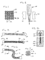
- Figure 1 is a cross-sectional view of an optical fiber bundle preform used to produce the fiber bundle in accordance with the present invention.
- Figure 2 is a schematic elevational view illustrating the drawing of the optical fiber bundle preform in order to form a fused optical fiber bundle.
- Figure 3 is an elevational view of the fused optical fiber bundle having ferrules installed on each end.
- Figure 4 is an elevational view similar to Figure 3 showing the fused optical fiber bundle of Figure 3 wrapped in an etching material resistant mesh.
- Figure 5 is an elevational view illustrating the leaching of the fused optical fiber bundle to remove the spacer material between the optic fibers to form a flexible leached fiber bundle.
- Figure 6 is an elevational view, partially broken away, of the flexible leached fiber bundle with the end ferrule after the leaching process.
- Figure 7 is a cross-sectional view of the flexible area of the leached fiber bundle showing an optional sheathing taken along line 7-7 in Figure 6 .
- array as used herein is intended to include any type of ordered, two-dimensional arrangement of fiber ends, such as for a flexible image bundle.
- the invention relates to a method of manufacturing a leached fiber bundle 10. a shown in Figure 6 , comprising a leaching agent resistant mesh which is adapted use as, for example, an image conductor or guide for endoscopes or for transmission of optical signals.
- the leached fiber bundle 10 includes a plurality of optic fibers 12 which may be as small as ten microns in diameter or smaller.
- the leached fiber bundle 10 may be enclosed in a sheathing ofprotective material 14, which is preferably a flexible polymeric material. However, the sheathing 14 is not necessary.
- a plurality of optic fiber preforms 20 are preferably arranged in an ordered array and spaced apart using leachable spacers 22 to form a fiber bundle preform 24, as shown in Figure 1 .
- the optical fiber preforms 20 are preferably formed from high index glass cores surrounded by a lower index cladding material.
- the optic fiber preforms 20 are preferably arranged in rectilinear pattern with the leachable spacers 22 being used to keep the optical fiber preforms 20 spaced apart from one another.
- the spacers 22 are preferably tubular as shown, with the optic fiber preforms 20 being located within the spacers 22.
- optical fiber preforms 20 and spacers 22 are shown as circular, those skilled in the art will recognize that other shapes could be utilized for the optic fiber preforms 20 and/or the spacers 22.
- the optic fiber preforms 20 and the spacers 22 could be rectilinear in order to hold the optical fiber preforms 20 in a predetermined spacial relation.
- the spacers 22 could be in the form of separate rods located in the spaces between the optic fiber preforms 20.
- the spacers 22 are preferably formed of an acid-soluble material, such as an acid-soluble glass. However, other suitable materials can be utilized.
- the optic fibers preforms 20 are preferably made of an etch resistant material.
- the fiber bundle preform 24 is preferably heated and drawn in the usual fashion by heating the fiber bundle preform 22 locally utilizing heaters 30 and pulling on the fiber bundle preform in the longitudinal direction to obtain a drawn fiber bundle 32 having a desired size and/or spacing of the optic fibers 12 within the bundle 32. This is preferably done in a drawing tower. However, other drawing arrangements may be utilized depending upon the particular circumstances.
- the drawn fiber bundle 32 is preferably cut to a desired length for further processing.
- end ferrules 34 are preferably placed over the ends and bonded and/or crimped in position.
- the end ferrules 34 and bonding agent are preferably made of an acid etch resistant material, or may be coated with an acid etch resistant material, if desired.
- the end ferrules 34 may be omitted or installed after leaching of the spacer material drawn fiber bundle 32. However, this entails higher costs and has a greater probability of damaging the optic fibers 12.
- An advantage of one embodiment of the present invention is to install the ferrules 34, which could be required for a particular connector arrangement or merely as protection for the ends of the leached fiber bundle 10, while the drawn fiber bundle 32 is still a single rigid structure in order to provide for easier handling and less damage to the optic fibers 12.
- a leaching resistant mesh 36 is installed over the drawn fiber bundle 32 prior to leaching the leachable material of the spacers 22 from the drawn fiber bundle 12.
- the mesh 36 is preferably formed of an acid resistant polymeric material, such as polyolefine, and may be an open mesh woven tube, net or a mesh fabric material which can be held in place on the drawn fiber bundle 32 via acid etch resistant straps or bands.
- the specific size and shape of the mesh may be varied based upon the diameter of the optic fibers 12 and/or the glass material being utilized.
- the mesh 36 could be formed of a woven fabric having the desired permeability.
- the mesh 36 must be open enough to allow free movement of leached material as well as the acid leaching agent therethrough.
- the drawn fiber bundle 32 with the protected ends which may be protected either through coating with an acid etch resistant material or via installation of the etch resistant ferrules 34, is placed in a leaching tank 44, which may contain, for example hydrochloric acid or any other suitable leachant, depending upon the composition of the leachable spacers 22.
- the spacer rod material is leached from a middle portion of the drawn fiber bundle 32 so that individual optic fibers 12 are free in the middle portion to form the leached fiber bundle 10.
- the leached fiber bundle 10 is ready for incorporation into an endoscope or for use as a optical signal transmission cable.
- the mesh 3 6 helps to prevent damage to the small diameter optic fibers 12 in the middle portion of the leached fiber bundle 10.
- a sheath such as the sheath 14 as shown in Figure 7
- An anti-friction powder 40 such as TOS-Pearls ® which are available from GE Bayer Silicone or other suitable anti-friction or parting powders such as talcum powder or PTFE powder may be utilized. This anti-friction powder 40 reduces abrasion and friction between the individual fibers 12 during flexing of the leached fiber bundle 10.
Landscapes
- Chemical & Material Sciences (AREA)
- Engineering & Computer Science (AREA)
- Life Sciences & Earth Sciences (AREA)
- Materials Engineering (AREA)
- Geochemistry & Mineralogy (AREA)
- General Life Sciences & Earth Sciences (AREA)
- Organic Chemistry (AREA)
- Physics & Mathematics (AREA)
- Manufacturing & Machinery (AREA)
- General Physics & Mathematics (AREA)
- Optics & Photonics (AREA)
- Chemical Kinetics & Catalysis (AREA)
- General Chemical & Material Sciences (AREA)
- Optical Fibers, Optical Fiber Cores, And Optical Fiber Bundles (AREA)
Description
- BACKGROUND
- The present invention relates to leached fiber bundles (LFBs) which are used in endoscopes and for optical signal communications, and more particularly, to improved methods of producing such LFBs with higher quality and reliability.
- It has been previously known to produce image conductors or guides for endoscopes or for transmitting optical signals in the form of LFBs. Such LFBs include a large number of optical fibers, which may be arranged in an ordered array, with each fiber having a small diameter, for example 10 - 100 microns. The LFBs may be formed by drawing a fiber bundle preform having a number of pre-arranged optic fiber preforms, in the form of glass rods and/or tubes, together with at least some leachable glass spacers located between or encapsulating each of the desired optic fiber preforms. The fiber bundle preform is drawn down to the desired size for the optical fibers, which are fused together with the leachable glass spacers as they are drawn, with the leachable glass spacers maintaining a space between the individual optic fibers. In order to form a flexible image guide, the ends of the fused optical fiber bundle are protected with a soft, etch resistant coating, and the leachable glass from the spacers is leached from the fused optical fiber bundle, typically using an acid etch bath. Once the leaching process is complete, the individual optical fibers in the middle portion of the leached optical fiber bundle are free and allow the LFB to be flexed, while the ends are still held together. Ferrules are then installed on the ends to protect the ends from damage and maintain the fibers in position. The flexible middle portion may be placed within a flexible outer sheath to prevent the individual optical fibers from being damaged.
-
US-A-4 389 089 is directed to a flexible image-conducting bundle of optical fibers produced by juxtapositioning and drawing a multiplicity of glass-clad glass fiber performs and interstitial rods of leachable glass. The drawn assembly is cut to desired length and interstitial glasses are leached from the intermediate portion of the cut piece. - Furthermore,
US-A-3 624 816 discloses a flexible fiber optic conduit formed of a multiplicity of juxtaposed light-conducting fibers all connected together adjacent opposite ends of the conduit by a matrix of silica-free acid soluble glass with said connecting glass having been leached from the intermediate portion of the bundle leaving corresponding lengths of individual fibers thereof unconnected and free to flex individually. - There are several problems with this prior known process. Due to the small size of the optic fibers, the individual fibers in the LFB are extremely sensitive to outside surface damage and breakage during handling, such as during removal from the etch bath and further processing, such as the installation of the end ferrules. This creates an additional expense due to the special handling required for such further operations. The optic fibers of the LFB can also suffer from damage or breakage during use in the final product or application, for example in a flexible endoscope, due to friction and abrasion between adjacent fibers as the middle, flexible portion of the LFB is flexed. This results in a loss of image definition and degradation of transmission capability. It would be advantageous to reduce the possibility of such optical fiber damage during the formation of the LFB and in the subsequent handling and production of the final product in which the LFB is utilized. It would also be advantageous to reduce production cost and provide a longer useful life for LFBs.
- SUMMARY
- Briefly stated, in one aspect the present invention provides a method of manufacturing a leached fiber bundle, which includes: (a) arranging a plurality of optic fiber preforms and leachable spacers to form a fiber bundle preform; (b) heating and drawing the fiber bundle preform to obtain a drawn fiber bundle having a desired size of optic fibers within the bundle; (c) polishing the optical ends of the drawn fiber bundle; (d) coating the ends of the drawn fiber bundle with a leaching agent resistant material; (e) leaching material from the spacers from a middle portion of the drawn fiber bundle so that individual optic fibers are free in the middle portion to form a flexible leached fiber bundle; (f) applying an anti-friction powder to the free middle portion of the optic fibers in the leached fiber bundle to reduce abrasion and friction between the optic fibers during flexing of the leached fiber bundle; and (g) applying a sheath over at least the middle portion of the leached fiber bundle, further comprising installing a leaching agent resistant mesh over the drawn fiber bundle prior to leaching the leachable material from the drawn fiber bundle.
- In another aspect, the invention provides a method of manufacturing a leached fiber bundle with reduced damage during production by: (a) arranging a plurality of optic fiber preforms and leachable spacers to form a fiber bundle preform; (b) heating and drawing the fiber bundle preform to obtain a drawn fiber bundle having a desired size of optic fibers within the bundle; (c) installing a ferrule on each of the ends of the drawn fiber bundle; (d) polishing the optical ends of the drawn fiber bundle; (e) coating the ends of the drawn fiber bundle with a leaching agent resistant material; (f) leaching material from the spacers from a middle portion of the drawn fiber bundle so that the optic fibers are free in the middle portion to form a flexible leached fiber bundle, and preferably (g) applying an anti-friction powder to the free middle portion of the optic fibers in the leached fiber bundle to reduce abrasion and friction between the optic fibers during flexing of the leached fiber bundle; and (h) applying a sheath over at least the middle portion of the leached fiber bundle, further comprising installing a leaching agent resistant mesh over the drawn fiber bundle prior to leaching the leachable material from the drawn fiber bundle. This reduces the increased cost involved with installing a ferrule on the ends of a LFB after it has been etched, and reduces the possibility of fiber damage.
- In another aspect, the invention provides a method of manufacturing a leached fiber bundle with reduced potential for fiber damage by: (a) arranging a plurality of optic fiber preforms and leachable spacers to form a fiber bundle preform; (b) heating and drawing the fiber bundle preform to obtain a drawn fiber bundle having a desired size of optic fibers within the bundle; (c) polishing the optical ends of the drawn fiber bundle; (d) coating the ends of the drawn fiber bundle with a leaching agent resistant material; (e) enclosing the drawn fiber bundle with a leaching agent resistant mesh; (f) leaching material from the spacers from a middle portion of the drawn fiber bundle so that the optic fibers are free in the middle portion to form a flexible leached fiber bundle; and preferably (g) applying an anti-friction powder to the free middle portion of the optic fibers in the leached fiber bundle to reduce abrasion and friction between the optic fibers during flexing of the leached fiber bundle; and (h) applying a sheath over at least the middle portion of the leached fiber bundle.
- One or more of the above methods can be utilized individually or in combination in order to produce LFBs with lower cost and less damage during manufacture, as well as higher reliability in the final end product.
- BRIEF DESCRIPTION OF THE DRAWINGS
- The foregoing summary, as well as the following detailed description of the preferred embodiments of the invention will be better understood when read in conjunction with the appended drawings. For the purpose of illustrating the invention, there are shown in the drawings embodiments which are presently preferred. It should be understood, however, that the invention is not limited to the precise arrangements shown.
-
Figure 1 is a cross-sectional view of an optical fiber bundle preform used to produce the fiber bundle in accordance with the present invention. -
Figure 2 is a schematic elevational view illustrating the drawing of the optical fiber bundle preform in order to form a fused optical fiber bundle. -
Figure 3 is an elevational view of the fused optical fiber bundle having ferrules installed on each end. -
Figure 4 is an elevational view similar toFigure 3 showing the fused optical fiber bundle ofFigure 3 wrapped in an etching material resistant mesh. -
Figure 5 is an elevational view illustrating the leaching of the fused optical fiber bundle to remove the spacer material between the optic fibers to form a flexible leached fiber bundle. -
Figure 6 is an elevational view, partially broken away, of the flexible leached fiber bundle with the end ferrule after the leaching process. -
Figure 7 is a cross-sectional view of the flexible area of the leached fiber bundle showing an optional sheathing taken along line 7-7 inFigure 6 . - DETAILED DESCRIPTION OF THE PREFERRED EMBODIMENTS
- Certain terminology is used in the following description for convenience only and is not considered limiting. The terms "a" and "one" are defined as including one or more of the referenced item unless specifically noted. The term "array" as used herein is intended to include any type of ordered, two-dimensional arrangement of fiber ends, such as for a flexible image bundle.
- The invention relates to a method of manufacturing a leached
fiber bundle 10. a shown inFigure 6 , comprising a leaching agent resistant mesh which is adapted use as, for example, an image conductor or guide for endoscopes or for transmission of optical signals. The leachedfiber bundle 10 includes a plurality ofoptic fibers 12 which may be as small as ten microns in diameter or smaller. As shown inFigure 7 , the leachedfiber bundle 10 may be enclosed in a sheathingofprotective material 14, which is preferably a flexible polymeric material. However, thesheathing 14 is not necessary. - In order to manufacture the leached
fiber bundle 10, a plurality ofoptic fiber preforms 20 are preferably arranged in an ordered array and spaced apart usingleachable spacers 22 to form afiber bundle preform 24, as shown inFigure 1 . Theoptical fiber preforms 20 are preferably formed from high index glass cores surrounded by a lower index cladding material. Theoptic fiber preforms 20 are preferably arranged in rectilinear pattern with theleachable spacers 22 being used to keep theoptical fiber preforms 20 spaced apart from one another. Thespacers 22 are preferably tubular as shown, with theoptic fiber preforms 20 being located within thespacers 22. While the optical fiber preforms 20 andspacers 22 are shown as circular, those skilled in the art will recognize that other shapes could be utilized for the optic fiber preforms 20 and/or thespacers 22. For example, the optic fiber preforms 20 and thespacers 22 could be rectilinear in order to hold theoptical fiber preforms 20 in a predetermined spacial relation. Alternatively, thespacers 22 could be in the form of separate rods located in the spaces between theoptic fiber preforms 20. - The
spacers 22 are preferably formed of an acid-soluble material, such as an acid-soluble glass. However, other suitable materials can be utilized. The optic fibers preforms 20 are preferably made of an etch resistant material. - As shown in
Figure 2 , thefiber bundle preform 24 is preferably heated and drawn in the usual fashion by heating the fiber bundle preform 22 locally utilizingheaters 30 and pulling on the fiber bundle preform in the longitudinal direction to obtain a drawnfiber bundle 32 having a desired size and/or spacing of theoptic fibers 12 within thebundle 32. This is preferably done in a drawing tower. However, other drawing arrangements may be utilized depending upon the particular circumstances. - The drawn
fiber bundle 32 is preferably cut to a desired length for further processing. As shown inFigure 3 ,end ferrules 34 are preferably placed over the ends and bonded and/or crimped in position. Theend ferrules 34 and bonding agent are preferably made of an acid etch resistant material, or may be coated with an acid etch resistant material, if desired. Depending upon the particular application, theend ferrules 34 may be omitted or installed after leaching of the spacer material drawnfiber bundle 32. However, this entails higher costs and has a greater probability of damaging theoptic fibers 12. An advantage of one embodiment of the present invention is to install theferrules 34, which could be required for a particular connector arrangement or merely as protection for the ends of the leachedfiber bundle 10, while the drawnfiber bundle 32 is still a single rigid structure in order to provide for easier handling and less damage to theoptic fibers 12. - As shown in
Figure 4 , it is in accordance with the invention that a leachingresistant mesh 36 is installed over the drawnfiber bundle 32 prior to leaching the leachable material of thespacers 22 from the drawnfiber bundle 12. Themesh 36 is preferably formed of an acid resistant polymeric material, such as polyolefine, and may be an open mesh woven tube, net or a mesh fabric material which can be held in place on the drawnfiber bundle 32 via acid etch resistant straps or bands. The specific size and shape of the mesh may be varied based upon the diameter of theoptic fibers 12 and/or the glass material being utilized. Themesh 36 could be formed of a woven fabric having the desired permeability. Themesh 36 must be open enough to allow free movement of leached material as well as the acid leaching agent therethrough. - As shown in
Figure 5 , the drawnfiber bundle 32 with the protected ends, which may be protected either through coating with an acid etch resistant material or via installation of the etchresistant ferrules 34, is placed in aleaching tank 44, which may contain, for example hydrochloric acid or any other suitable leachant, depending upon the composition of theleachable spacers 22. The spacer rod material is leached from a middle portion of the drawnfiber bundle 32 so that individualoptic fibers 12 are free in the middle portion to form the leachedfiber bundle 10. - After sufficient neutralization and/or rinsing of the leached
fiber bundle 10, the leachedfiber bundle 10 is ready for incorporation into an endoscope or for use as a optical signal transmission cable. - In accordance with the invention, the mesh 3 6 helps to prevent damage to the small
diameter optic fibers 12 in the middle portion of the leachedfiber bundle 10. In one aspect of the invention, a sheath, such as thesheath 14 as shown inFigure 7 , is applied over at least a portion of the leachedfiber bundle 10 to provide protection for theoptic fibers 12. An anti-friction powder 40, such as TOS-Pearls® which are available from GE Bayer Silicone or other suitable anti-friction or parting powders such as talcum powder or PTFE powder may be utilized. This anti-friction powder 40 reduces abrasion and friction between theindividual fibers 12 during flexing of the leachedfiber bundle 10. This helps to prevent premature wear and breakage of the individual fibers in the leachedfiber bundle 10 which lead to degradation and loss of images or signals being transmitted through the leachedfiber bundle 10. Utilizing the anti-friction powder leads to increased product life as compared to the prior known bundles. - Through the use of the methods in accordance with the present invention, it is possible to provide higher quality leached
fiber bundles 12 with less damage to the individualoptic fibers 12 during the manufacturing process. This produces higher yields and less scrapage due to manufacturing defects, leading to overall reduced production costs due to less rejects. Additionally, the reliability and life of the leached optic fiber bundle in use can be substantially increased.
Claims (13)
- Method of manufacturing a leached fiber bundle, comprising: arranging a plurality of optic fiber preforms and leachable spacers to form a fiber bundle preform; heating and drawing the fiber bundle preform to obtain a drawn fiber bundle having a desired size of optic fibers within the bundle; coating ends of the drawn fiber bundle with a leaching agent resistant material leaching material from the spacers from a middle portion of the drawn fiber bundle so that the optic fibers in the middle portion are free to form a flexible leached fiber bundle; applying an anti-friction powder to the free fibers in the middle portion of the leached fiber bundle to reduce abrasion and friction between the individual fibers during flexing of the leached fiber bundle; and applying a sheath over the middle portion of the leached fiber bundle, further comprising installing a leaching agent resistant mesh over the drawn fiber bundle prior to leaching the leachable material from the drawn fiber bundle.
- The method of claim 1, wherein the anti-friction powder comprises TOS Pearls.
- The method of claim 1, further comprising installing a ferrule on at least one end of the drawn fiber bundle prior to etching.
- The method of claim 3, wherein the ferrule is resistant to the leaching agent.
- The method of claim 1, wherein a leaching agent resistant coating is located over the ferrule.
- The method of claim 1, further comprising applying the sheath over the mesh.
- The method of claim 1, further comprising polishing the ends of the drawn fiber bundle prior to coating with the leaching agent resistant material.
- Method of manufacturing a leached fiber bundle, comprising: arranging a plurality of optic fiber preforms and leachable spacers to form a fiber bundle preform; heating and drawing the fiber bundle preform to obtain a drawn fiber bundle having a desired size of optic fibers within the bundle; installing a ferrule on each of the ends of the drawn fiber bundle; and leaching material from the spacers from a middle portion of the drawn fiber bundle so that the optic fibers are free in the middle portion to form a flexible leached fiber bundle, further comprising installing a leaching agent resistant mesh over the drawn fiber bundle prior to leaching the leachable material from the drawn fiber bundle.
- The method of claim 8, further comprising polishing ends of the drawn fiber bundle prior and coating the ends with a the leaching agent resistant material prior to leaching.
- The method of claim 8, further comprising applying a sheath over the middle portion of the leached fiber bundle.
- Method of manufacturing a leached fiber bundle, comprising: arranging a plurality of optic fiber preforms and leachable spacers to form a fiber bundle preform; heating and drawing the fiber bundle preform to obtain a drawn fiber bundle having a desired size of optic fibers within the bundle; coating the ends of the drawn fiber bundle with a leaching agent resistant material; enclosing the drawn fiber bundle with a leaching agent resistant mesh; and leaching material from the spacers from a middle portion of the drawn fiber bundle so that the optic fibers are free in the middle portion to form a flexible leached fiber bundle.
- The method of claim 11, further comprising polishing ends of the drawn fiber bundle prior and coating the ends with the leaching agent resistant material prior to leaching.
- The method of claim 11, further comprising applying a sheath over the middle portion of the leached fiber bundle.
Applications Claiming Priority (7)
| Application Number | Priority Date | Filing Date | Title |
|---|---|---|---|
| US24919300P | 2000-11-16 | 2000-11-16 | |
| US24919100P | 2000-11-16 | 2000-11-16 | |
| US24919200P | 2000-11-16 | 2000-11-16 | |
| US249191P | 2000-11-16 | ||
| US249192P | 2000-11-16 | ||
| US249193P | 2000-11-16 | ||
| PCT/US2001/043203 WO2002040416A1 (en) | 2000-11-16 | 2001-11-16 | Improved leached fiber bundle and method |
Publications (3)
| Publication Number | Publication Date |
|---|---|
| EP1409422A1 EP1409422A1 (en) | 2004-04-21 |
| EP1409422A4 EP1409422A4 (en) | 2006-09-13 |
| EP1409422B1 true EP1409422B1 (en) | 2013-04-17 |
Family
ID=27400187
Family Applications (1)
| Application Number | Title | Priority Date | Filing Date |
|---|---|---|---|
| EP01995121.9A Expired - Lifetime EP1409422B1 (en) | 2000-11-16 | 2001-11-16 | Method for manufacturing a leached fiber bundle |
Country Status (5)
| Country | Link |
|---|---|
| US (1) | US7308807B2 (en) |
| EP (1) | EP1409422B1 (en) |
| CN (1) | CN1318335C (en) |
| AU (1) | AU2002225632A1 (en) |
| WO (1) | WO2002040416A1 (en) |
Families Citing this family (12)
| Publication number | Priority date | Publication date | Assignee | Title |
|---|---|---|---|---|
| DE10240508A1 (en) * | 2002-09-03 | 2004-03-11 | Schott Glas | Etched or leached optic fiber bundle is produced from a number of fiber and spacer preforms with gaps formed between them to be filled with an adhesive and subsequent removal of the spacers |
| US7697807B2 (en) * | 2006-06-01 | 2010-04-13 | Ut-Battelle, Llc | Multi-tipped optical component |
| US7697808B2 (en) * | 2004-07-27 | 2010-04-13 | Ut-Battelle, Llc | Multi-tipped optical component |
| US7419308B2 (en) * | 2006-09-15 | 2008-09-02 | The Boeing Company | Fiber bundle termination with reduced fiber-to-fiber pitch |
| US7430350B1 (en) * | 2007-04-16 | 2008-09-30 | Karl Storz Endovision, Inc. | Multi-length flexible image bundle |
| DE102009022118A1 (en) * | 2009-05-20 | 2010-11-25 | Karl Storz Gmbh & Co. Kg | endoscope |
| US9828284B2 (en) | 2014-03-28 | 2017-11-28 | Ut-Battelle, Llc | Thermal history-based etching |
| US10429564B2 (en) | 2014-07-09 | 2019-10-01 | Sunoptic Technologies Llc | Fiberoptic lightguide and method of manufacture |
| GB201700936D0 (en) | 2017-01-19 | 2017-03-08 | Univ Bath | Optical fibre apparatus and method |
| CN107059836B (en) * | 2017-05-31 | 2018-10-12 | 泰安路德工程材料有限公司 | Intelligent composite geotextile material of a kind of durable type height and preparation method thereof |
| CN114355511B (en) * | 2022-01-14 | 2024-02-06 | 武汉锐科光纤激光技术股份有限公司 | Optical fiber etching device |
| CN121336132A (en) | 2023-07-26 | 2026-01-13 | 肖特股份有限公司 | Flexible optical waveguide |
Family Cites Families (11)
| Publication number | Priority date | Publication date | Assignee | Title |
|---|---|---|---|---|
| US3004368A (en) * | 1958-06-10 | 1961-10-17 | American Optical Corp | Manufacture of fiber optical devices |
| US3050907A (en) * | 1958-06-27 | 1962-08-28 | American Optical Corp | Method for shaping a fiber optical device |
| US3624816A (en) * | 1970-01-28 | 1971-11-30 | American Optical Corp | Flexible fiber optic conduit |
| US3653739A (en) * | 1970-07-02 | 1972-04-04 | American Optical Corp | Leachable bundle of optical fibers |
| US3690853A (en) * | 1970-08-19 | 1972-09-12 | Optics Technology Inc | Method of making high resolution image transmitting fiber optics bundles |
| US4080045A (en) * | 1973-12-26 | 1978-03-21 | Olympus Optical Co., Ltd. | Optical fiber bundle with reinforced end portions |
| US4389089A (en) * | 1980-07-14 | 1983-06-21 | Warner Lambert Technologies, Inc. | Flexible fiber optical conduit and method of making |
| JPS5972408A (en) | 1982-10-19 | 1984-04-24 | Asahi Optical Co Ltd | Manufacture of flexible optical fiber bundle |
| GB8504535D0 (en) * | 1985-02-21 | 1985-03-27 | Barr & Stroud Ltd | Flexible optical fibre bundles |
| JPS62153129A (en) | 1985-12-26 | 1987-07-08 | Asahi Optical Co Ltd | Production of flexible optical fiber bundle |
| US5716322A (en) * | 1996-03-13 | 1998-02-10 | Johnson & Johnson Medical, Inc. | Medical instrument and method for lubrication and sterilization thereof |
-
2001
- 2001-11-16 EP EP01995121.9A patent/EP1409422B1/en not_active Expired - Lifetime
- 2001-11-16 US US10/416,897 patent/US7308807B2/en not_active Expired - Lifetime
- 2001-11-16 CN CNB018189830A patent/CN1318335C/en not_active Expired - Lifetime
- 2001-11-16 AU AU2002225632A patent/AU2002225632A1/en not_active Abandoned
- 2001-11-16 WO PCT/US2001/043203 patent/WO2002040416A1/en not_active Ceased
Also Published As
| Publication number | Publication date |
|---|---|
| EP1409422A1 (en) | 2004-04-21 |
| AU2002225632A1 (en) | 2002-05-27 |
| WO2002040416A1 (en) | 2002-05-23 |
| CN1474787A (en) | 2004-02-11 |
| CN1318335C (en) | 2007-05-30 |
| US7308807B2 (en) | 2007-12-18 |
| EP1409422A4 (en) | 2006-09-13 |
| WO2002040416A8 (en) | 2002-07-04 |
| US20040093906A1 (en) | 2004-05-20 |
Similar Documents
| Publication | Publication Date | Title |
|---|---|---|
| US3624816A (en) | Flexible fiber optic conduit | |
| US7308807B2 (en) | Method of manufacturing a leached fiber bundle | |
| CN111190251B (en) | Method for manufacturing large-section high-resolution flexible optical fiber image transmission bundle | |
| EP2278372B1 (en) | Fiber optic cables and methods for forming the same | |
| US4028081A (en) | Method for manufacturing helical optical fiber | |
| US5201020A (en) | Reinforced protective tube for optical waveguide fibers | |
| GB1595638A (en) | Optical waveguides with protective coating | |
| US3653739A (en) | Leachable bundle of optical fibers | |
| US5016973A (en) | Cable reinforcement for an optical fiber cable | |
| US20220260796A1 (en) | Sz stranded tight-buffered ribbon stacks with binder film | |
| US5210814A (en) | High resolution optical device with rigid fiber optic bundle | |
| US20130301999A1 (en) | Fiber-optic image guide comprising polyhedron rods | |
| US20240165868A1 (en) | Multi-material fibers and methods of manufacturing the same | |
| US11886026B2 (en) | Optical fiber ribbon, optical fiber cable, and connector-equipped optical fiber cord | |
| CN116125589B (en) | Large-section high-resolution flexible optical fiber image transmission beam and preparation method thereof | |
| US4375314A (en) | Infrared optical fiber | |
| Cryan | Two-dimensional multimode fibre array for optical interconnects | |
| WO2025021671A1 (en) | Flexible optical waveguides | |
| KR100851047B1 (en) | Optical fiber having air holes and manufacturing method thereof | |
| RU2273608C2 (en) | Improved leached optical fiber bundle and the method of its production | |
| WO2002102578A1 (en) | Method of forming an ordered array of fibers | |
| EP1983358B1 (en) | Multi-length flexible image bundle | |
| JPS621331B2 (en) | ||
| JP3841849B2 (en) | Method for producing radiation-resistant tape-type multi-core fiber | |
| JP2519699B2 (en) | Optical fiber bundle manufacturing method |
Legal Events
| Date | Code | Title | Description |
|---|---|---|---|
| PUAI | Public reference made under article 153(3) epc to a published international application that has entered the european phase |
Free format text: ORIGINAL CODE: 0009012 |
|
| 17P | Request for examination filed |
Effective date: 20030516 |
|
| AK | Designated contracting states |
Kind code of ref document: A1 Designated state(s): AT BE CH CY DE DK ES FI FR GB GR IE IT LI LU MC NL PT SE TR |
|
| AX | Request for extension of the european patent |
Extension state: AL LT LV MK RO SI |
|
| RAP1 | Party data changed (applicant data changed or rights of an application transferred) |
Owner name: SCHOTT AG |
|
| A4 | Supplementary search report drawn up and despatched |
Effective date: 20060816 |
|
| RIC1 | Information provided on ipc code assigned before grant |
Ipc: G02B 6/06 20060101ALI20060809BHEP Ipc: C03B 37/15 20060101ALI20060809BHEP Ipc: C03B 40/033 20060101ALI20060809BHEP Ipc: C03B 37/023 20060101ALI20060809BHEP Ipc: C03B 37/028 20060101AFI20020529BHEP |
|
| 17Q | First examination report despatched |
Effective date: 20091029 |
|
| GRAP | Despatch of communication of intention to grant a patent |
Free format text: ORIGINAL CODE: EPIDOSNIGR1 |
|
| GRAJ | Information related to disapproval of communication of intention to grant by the applicant or resumption of examination proceedings by the epo deleted |
Free format text: ORIGINAL CODE: EPIDOSDIGR1 |
|
| GRAP | Despatch of communication of intention to grant a patent |
Free format text: ORIGINAL CODE: EPIDOSNIGR1 |
|
| GRAS | Grant fee paid |
Free format text: ORIGINAL CODE: EPIDOSNIGR3 |
|
| GRAA | (expected) grant |
Free format text: ORIGINAL CODE: 0009210 |
|
| AK | Designated contracting states |
Kind code of ref document: B1 Designated state(s): AT BE CH CY DE DK ES FI FR GB GR IE IT LI LU MC NL PT SE TR |
|
| REG | Reference to a national code |
Ref country code: GB Ref legal event code: FG4D |
|
| REG | Reference to a national code |
Ref country code: DE Ref legal event code: R082 Ref document number: 60147898 Country of ref document: DE Representative=s name: ADOLF - LUEKEN - HOEFLICH - SAWODNY RECHTS- UN, DE |
|
| REG | Reference to a national code |
Ref country code: CH Ref legal event code: EP |
|
| REG | Reference to a national code |
Ref country code: IE Ref legal event code: FG4D |
|
| REG | Reference to a national code |
Ref country code: AT Ref legal event code: REF Ref document number: 607187 Country of ref document: AT Kind code of ref document: T Effective date: 20130515 |
|
| REG | Reference to a national code |
Ref country code: DE Ref legal event code: R096 Ref document number: 60147898 Country of ref document: DE Effective date: 20130613 |
|
| REG | Reference to a national code |
Ref country code: AT Ref legal event code: MK05 Ref document number: 607187 Country of ref document: AT Kind code of ref document: T Effective date: 20130417 |
|
| REG | Reference to a national code |
Ref country code: NL Ref legal event code: VDEP Effective date: 20130417 |
|
| PG25 | Lapsed in a contracting state [announced via postgrant information from national office to epo] |
Ref country code: FI Free format text: LAPSE BECAUSE OF FAILURE TO SUBMIT A TRANSLATION OF THE DESCRIPTION OR TO PAY THE FEE WITHIN THE PRESCRIBED TIME-LIMIT Effective date: 20130417 Ref country code: GR Free format text: LAPSE BECAUSE OF FAILURE TO SUBMIT A TRANSLATION OF THE DESCRIPTION OR TO PAY THE FEE WITHIN THE PRESCRIBED TIME-LIMIT Effective date: 20130718 Ref country code: AT Free format text: LAPSE BECAUSE OF FAILURE TO SUBMIT A TRANSLATION OF THE DESCRIPTION OR TO PAY THE FEE WITHIN THE PRESCRIBED TIME-LIMIT Effective date: 20130417 Ref country code: PT Free format text: LAPSE BECAUSE OF FAILURE TO SUBMIT A TRANSLATION OF THE DESCRIPTION OR TO PAY THE FEE WITHIN THE PRESCRIBED TIME-LIMIT Effective date: 20130819 Ref country code: SE Free format text: LAPSE BECAUSE OF FAILURE TO SUBMIT A TRANSLATION OF THE DESCRIPTION OR TO PAY THE FEE WITHIN THE PRESCRIBED TIME-LIMIT Effective date: 20130417 Ref country code: ES Free format text: LAPSE BECAUSE OF FAILURE TO SUBMIT A TRANSLATION OF THE DESCRIPTION OR TO PAY THE FEE WITHIN THE PRESCRIBED TIME-LIMIT Effective date: 20130728 Ref country code: BE Free format text: LAPSE BECAUSE OF FAILURE TO SUBMIT A TRANSLATION OF THE DESCRIPTION OR TO PAY THE FEE WITHIN THE PRESCRIBED TIME-LIMIT Effective date: 20130417 |
|
| PG25 | Lapsed in a contracting state [announced via postgrant information from national office to epo] |
Ref country code: CY Free format text: LAPSE BECAUSE OF FAILURE TO SUBMIT A TRANSLATION OF THE DESCRIPTION OR TO PAY THE FEE WITHIN THE PRESCRIBED TIME-LIMIT Effective date: 20130417 |
|
| PG25 | Lapsed in a contracting state [announced via postgrant information from national office to epo] |
Ref country code: DK Free format text: LAPSE BECAUSE OF FAILURE TO SUBMIT A TRANSLATION OF THE DESCRIPTION OR TO PAY THE FEE WITHIN THE PRESCRIBED TIME-LIMIT Effective date: 20130417 |
|
| PLBE | No opposition filed within time limit |
Free format text: ORIGINAL CODE: 0009261 |
|
| STAA | Information on the status of an ep patent application or granted ep patent |
Free format text: STATUS: NO OPPOSITION FILED WITHIN TIME LIMIT |
|
| PG25 | Lapsed in a contracting state [announced via postgrant information from national office to epo] |
Ref country code: NL Free format text: LAPSE BECAUSE OF FAILURE TO SUBMIT A TRANSLATION OF THE DESCRIPTION OR TO PAY THE FEE WITHIN THE PRESCRIBED TIME-LIMIT Effective date: 20130417 Ref country code: IT Free format text: LAPSE BECAUSE OF FAILURE TO SUBMIT A TRANSLATION OF THE DESCRIPTION OR TO PAY THE FEE WITHIN THE PRESCRIBED TIME-LIMIT Effective date: 20130417 |
|
| 26N | No opposition filed |
Effective date: 20140120 |
|
| REG | Reference to a national code |
Ref country code: DE Ref legal event code: R097 Ref document number: 60147898 Country of ref document: DE Effective date: 20140120 |
|
| REG | Reference to a national code |
Ref country code: CH Ref legal event code: PL |
|
| PG25 | Lapsed in a contracting state [announced via postgrant information from national office to epo] |
Ref country code: CH Free format text: LAPSE BECAUSE OF NON-PAYMENT OF DUE FEES Effective date: 20131130 Ref country code: LI Free format text: LAPSE BECAUSE OF NON-PAYMENT OF DUE FEES Effective date: 20131130 Ref country code: MC Free format text: LAPSE BECAUSE OF FAILURE TO SUBMIT A TRANSLATION OF THE DESCRIPTION OR TO PAY THE FEE WITHIN THE PRESCRIBED TIME-LIMIT Effective date: 20130417 |
|
| REG | Reference to a national code |
Ref country code: FR Ref legal event code: ST Effective date: 20140731 |
|
| REG | Reference to a national code |
Ref country code: IE Ref legal event code: MM4A |
|
| PG25 | Lapsed in a contracting state [announced via postgrant information from national office to epo] |
Ref country code: IE Free format text: LAPSE BECAUSE OF NON-PAYMENT OF DUE FEES Effective date: 20131116 |
|
| PG25 | Lapsed in a contracting state [announced via postgrant information from national office to epo] |
Ref country code: FR Free format text: LAPSE BECAUSE OF NON-PAYMENT OF DUE FEES Effective date: 20131202 |
|
| PG25 | Lapsed in a contracting state [announced via postgrant information from national office to epo] |
Ref country code: TR Free format text: LAPSE BECAUSE OF FAILURE TO SUBMIT A TRANSLATION OF THE DESCRIPTION OR TO PAY THE FEE WITHIN THE PRESCRIBED TIME-LIMIT Effective date: 20130417 |
|
| PG25 | Lapsed in a contracting state [announced via postgrant information from national office to epo] |
Ref country code: LU Free format text: LAPSE BECAUSE OF NON-PAYMENT OF DUE FEES Effective date: 20131116 |
|
| PGFP | Annual fee paid to national office [announced via postgrant information from national office to epo] |
Ref country code: GB Payment date: 20201120 Year of fee payment: 20 Ref country code: DE Payment date: 20201119 Year of fee payment: 20 |
|
| REG | Reference to a national code |
Ref country code: DE Ref legal event code: R071 Ref document number: 60147898 Country of ref document: DE |
|
| REG | Reference to a national code |
Ref country code: GB Ref legal event code: PE20 Expiry date: 20211115 |
|
| PG25 | Lapsed in a contracting state [announced via postgrant information from national office to epo] |
Ref country code: GB Free format text: LAPSE BECAUSE OF EXPIRATION OF PROTECTION Effective date: 20211115 |