EP1408680A2 - Media clamping apparatus and method for an external drum imaging system. - Google Patents
Media clamping apparatus and method for an external drum imaging system. Download PDFInfo
- Publication number
- EP1408680A2 EP1408680A2 EP03102674A EP03102674A EP1408680A2 EP 1408680 A2 EP1408680 A2 EP 1408680A2 EP 03102674 A EP03102674 A EP 03102674A EP 03102674 A EP03102674 A EP 03102674A EP 1408680 A2 EP1408680 A2 EP 1408680A2
- Authority
- EP
- European Patent Office
- Prior art keywords
- external drum
- leading edge
- printing plate
- clamping
- imaging system
- Prior art date
- Legal status (The legal status is an assumption and is not a legal conclusion. Google has not performed a legal analysis and makes no representation as to the accuracy of the status listed.)
- Withdrawn
Links
- 238000003384 imaging method Methods 0.000 title claims abstract description 49
- 238000000034 method Methods 0.000 title claims abstract description 10
- 230000007246 mechanism Effects 0.000 description 44
- 239000000463 material Substances 0.000 description 4
- 230000003287 optical effect Effects 0.000 description 4
- 230000005855 radiation Effects 0.000 description 3
- 239000000758 substrate Substances 0.000 description 3
- 229910052782 aluminium Inorganic materials 0.000 description 2
- XAGFODPZIPBFFR-UHFFFAOYSA-N aluminium Chemical compound [Al] XAGFODPZIPBFFR-UHFFFAOYSA-N 0.000 description 2
- 238000012986 modification Methods 0.000 description 2
- 230000004048 modification Effects 0.000 description 2
- 229920000728 polyester Polymers 0.000 description 2
- 229920002943 EPDM rubber Polymers 0.000 description 1
- 229910000639 Spring steel Inorganic materials 0.000 description 1
- 230000008878 coupling Effects 0.000 description 1
- 238000010168 coupling process Methods 0.000 description 1
- 238000005859 coupling reaction Methods 0.000 description 1
- 230000001419 dependent effect Effects 0.000 description 1
- 238000003708 edge detection Methods 0.000 description 1
- 229920001971 elastomer Polymers 0.000 description 1
- 239000000806 elastomer Substances 0.000 description 1
- 239000003562 lightweight material Substances 0.000 description 1
- 229910052751 metal Inorganic materials 0.000 description 1
- 239000002184 metal Substances 0.000 description 1
- 229920003023 plastic Polymers 0.000 description 1
- 229920001084 poly(chloroprene) Polymers 0.000 description 1
- 229920001296 polysiloxane Polymers 0.000 description 1
Images


Classifications
-
- B—PERFORMING OPERATIONS; TRANSPORTING
- B41—PRINTING; LINING MACHINES; TYPEWRITERS; STAMPS
- B41C—PROCESSES FOR THE MANUFACTURE OR REPRODUCTION OF PRINTING SURFACES
- B41C1/00—Forme preparation
- B41C1/10—Forme preparation for lithographic printing; Master sheets for transferring a lithographic image to the forme
- B41C1/1083—Mechanical aspects of off-press plate preparation
-
- B—PERFORMING OPERATIONS; TRANSPORTING
- B41—PRINTING; LINING MACHINES; TYPEWRITERS; STAMPS
- B41F—PRINTING MACHINES OR PRESSES
- B41F27/00—Devices for attaching printing elements or formes to supports
- B41F27/12—Devices for attaching printing elements or formes to supports for attaching flexible printing formes
- B41F27/1212—Devices for attaching printing elements or formes to supports for attaching flexible printing formes using pneumatic force
-
- B—PERFORMING OPERATIONS; TRANSPORTING
- B41—PRINTING; LINING MACHINES; TYPEWRITERS; STAMPS
- B41F—PRINTING MACHINES OR PRESSES
- B41F27/00—Devices for attaching printing elements or formes to supports
- B41F27/12—Devices for attaching printing elements or formes to supports for attaching flexible printing formes
- B41F27/1262—Devices for attaching printing elements or formes to supports for attaching flexible printing formes without tensioning means
- B41F27/1268—Devices for attaching printing elements or formes to supports for attaching flexible printing formes without tensioning means by self-locking or snap-on means
-
- B—PERFORMING OPERATIONS; TRANSPORTING
- B41—PRINTING; LINING MACHINES; TYPEWRITERS; STAMPS
- B41J—TYPEWRITERS; SELECTIVE PRINTING MECHANISMS, i.e. MECHANISMS PRINTING OTHERWISE THAN FROM A FORME; CORRECTION OF TYPOGRAPHICAL ERRORS
- B41J11/00—Devices or arrangements of selective printing mechanisms, e.g. ink-jet printers or thermal printers, for supporting or handling copy material in sheet or web form
- B41J11/02—Platens
- B41J11/04—Roller platens
- B41J11/057—Structure of the surface
-
- B—PERFORMING OPERATIONS; TRANSPORTING
- B41—PRINTING; LINING MACHINES; TYPEWRITERS; STAMPS
- B41J—TYPEWRITERS; SELECTIVE PRINTING MECHANISMS, i.e. MECHANISMS PRINTING OTHERWISE THAN FROM A FORME; CORRECTION OF TYPOGRAPHICAL ERRORS
- B41J13/00—Devices or arrangements of selective printing mechanisms, e.g. ink-jet printers or thermal printers, specially adapted for supporting or handling copy material in short lengths, e.g. sheets
- B41J13/10—Sheet holders, retainers, movable guides, or stationary guides
- B41J13/22—Clamps or grippers
- B41J13/223—Clamps or grippers on rotatable drums
-
- B—PERFORMING OPERATIONS; TRANSPORTING
- B65—CONVEYING; PACKING; STORING; HANDLING THIN OR FILAMENTARY MATERIAL
- B65H—HANDLING THIN OR FILAMENTARY MATERIAL, e.g. SHEETS, WEBS, CABLES
- B65H5/00—Feeding articles separated from piles; Feeding articles to machines
- B65H5/08—Feeding articles separated from piles; Feeding articles to machines by grippers, e.g. suction grippers
- B65H5/12—Revolving grippers, e.g. mounted on arms, frames or cylinders
-
- H—ELECTRICITY
- H04—ELECTRIC COMMUNICATION TECHNIQUE
- H04N—PICTORIAL COMMUNICATION, e.g. TELEVISION
- H04N1/00—Scanning, transmission or reproduction of documents or the like, e.g. facsimile transmission; Details thereof
- H04N1/04—Scanning arrangements, i.e. arrangements for the displacement of active reading or reproducing elements relative to the original or reproducing medium, or vice versa
- H04N1/06—Scanning arrangements, i.e. arrangements for the displacement of active reading or reproducing elements relative to the original or reproducing medium, or vice versa using cylindrical picture-bearing surfaces, i.e. scanning a main-scanning line substantially perpendicular to the axis and lying in a curved cylindrical surface
- H04N1/0607—Scanning a concave surface, e.g. with internal drum type scanners
- H04N1/0614—Scanning a concave surface, e.g. with internal drum type scanners with main-scanning by rotation of the picture-bearing surface
-
- H—ELECTRICITY
- H04—ELECTRIC COMMUNICATION TECHNIQUE
- H04N—PICTORIAL COMMUNICATION, e.g. TELEVISION
- H04N1/00—Scanning, transmission or reproduction of documents or the like, e.g. facsimile transmission; Details thereof
- H04N1/04—Scanning arrangements, i.e. arrangements for the displacement of active reading or reproducing elements relative to the original or reproducing medium, or vice versa
- H04N1/06—Scanning arrangements, i.e. arrangements for the displacement of active reading or reproducing elements relative to the original or reproducing medium, or vice versa using cylindrical picture-bearing surfaces, i.e. scanning a main-scanning line substantially perpendicular to the axis and lying in a curved cylindrical surface
- H04N1/0671—Scanning arrangements, i.e. arrangements for the displacement of active reading or reproducing elements relative to the original or reproducing medium, or vice versa using cylindrical picture-bearing surfaces, i.e. scanning a main-scanning line substantially perpendicular to the axis and lying in a curved cylindrical surface with sub-scanning by translational movement of the main-scanning components
-
- H—ELECTRICITY
- H04—ELECTRIC COMMUNICATION TECHNIQUE
- H04N—PICTORIAL COMMUNICATION, e.g. TELEVISION
- H04N1/00—Scanning, transmission or reproduction of documents or the like, e.g. facsimile transmission; Details thereof
- H04N1/04—Scanning arrangements, i.e. arrangements for the displacement of active reading or reproducing elements relative to the original or reproducing medium, or vice versa
- H04N1/06—Scanning arrangements, i.e. arrangements for the displacement of active reading or reproducing elements relative to the original or reproducing medium, or vice versa using cylindrical picture-bearing surfaces, i.e. scanning a main-scanning line substantially perpendicular to the axis and lying in a curved cylindrical surface
- H04N1/08—Mechanisms for mounting or holding the sheet around the drum
- H04N1/0804—Holding methods
- H04N1/0813—Holding sides of the sheet which are substantially parallel to the drum axis
-
- H—ELECTRICITY
- H04—ELECTRIC COMMUNICATION TECHNIQUE
- H04N—PICTORIAL COMMUNICATION, e.g. TELEVISION
- H04N1/00—Scanning, transmission or reproduction of documents or the like, e.g. facsimile transmission; Details thereof
- H04N1/04—Scanning arrangements, i.e. arrangements for the displacement of active reading or reproducing elements relative to the original or reproducing medium, or vice versa
- H04N1/06—Scanning arrangements, i.e. arrangements for the displacement of active reading or reproducing elements relative to the original or reproducing medium, or vice versa using cylindrical picture-bearing surfaces, i.e. scanning a main-scanning line substantially perpendicular to the axis and lying in a curved cylindrical surface
- H04N1/08—Mechanisms for mounting or holding the sheet around the drum
- H04N1/083—Holding means
- H04N1/0834—Flexible holding means, e.g. envelopes or sheaths
-
- H—ELECTRICITY
- H04—ELECTRIC COMMUNICATION TECHNIQUE
- H04N—PICTORIAL COMMUNICATION, e.g. TELEVISION
- H04N1/00—Scanning, transmission or reproduction of documents or the like, e.g. facsimile transmission; Details thereof
- H04N1/04—Scanning arrangements, i.e. arrangements for the displacement of active reading or reproducing elements relative to the original or reproducing medium, or vice versa
- H04N1/06—Scanning arrangements, i.e. arrangements for the displacement of active reading or reproducing elements relative to the original or reproducing medium, or vice versa using cylindrical picture-bearing surfaces, i.e. scanning a main-scanning line substantially perpendicular to the axis and lying in a curved cylindrical surface
- H04N1/08—Mechanisms for mounting or holding the sheet around the drum
- H04N1/083—Holding means
- H04N1/0839—Mechanical clamps, i.e. means for holding the sheet against the drum by mechanical force
-
- B—PERFORMING OPERATIONS; TRANSPORTING
- B65—CONVEYING; PACKING; STORING; HANDLING THIN OR FILAMENTARY MATERIAL
- B65H—HANDLING THIN OR FILAMENTARY MATERIAL, e.g. SHEETS, WEBS, CABLES
- B65H2402/00—Constructional details of the handling apparatus
- B65H2402/50—Machine elements
- B65H2402/54—Springs, e.g. helical or leaf springs
-
- B—PERFORMING OPERATIONS; TRANSPORTING
- B65—CONVEYING; PACKING; STORING; HANDLING THIN OR FILAMENTARY MATERIAL
- B65H—HANDLING THIN OR FILAMENTARY MATERIAL, e.g. SHEETS, WEBS, CABLES
- B65H2555/00—Actuating means
- B65H2555/10—Actuating means linear
- B65H2555/11—Actuating means linear pneumatic, e.g. inflatable elements
-
- B—PERFORMING OPERATIONS; TRANSPORTING
- B65—CONVEYING; PACKING; STORING; HANDLING THIN OR FILAMENTARY MATERIAL
- B65H—HANDLING THIN OR FILAMENTARY MATERIAL, e.g. SHEETS, WEBS, CABLES
- B65H2701/00—Handled material; Storage means
- B65H2701/10—Handled articles or webs
- B65H2701/19—Specific article or web
- B65H2701/1928—Printing plate
Definitions
- the present invention is in the field of imaging systems. More particularly, the present invention provides an apparatus and method for clamping the leading edge of a recording media, such as a printing plate, on the external drum of an imaging system.
- a recording media such as a printing plate
- a movable optical carriage is commonly used to displace an image recording source in a slow scan direction while a cylindrical drum, having recording media mounted on an external surface thereof, is rotated with respect to the image recording source.
- the drum rotation causes the recording media to advance past the image recording source along a fast scan direction that is substantially perpendicular to the slow scan direction.
- the image recording source may include an optical system for generating one or more imaging beams that are scanned across the surface of the recording media. Each imaging beam may be separately modulated according to a digital information signal representing data corresponding to the image to be recorded.
- the recording media to be imaged by an external drum imaging system is commonly supplied in discrete, flexible sheets, hereinafter collectively referred to as "printing plates".
- Each printing plate may comprise one or more layers supported by a support substrate, which for many printing plates is a plano-graphic aluminum sheet.
- Other layers may include one or more image recording (i.e., "imageable") layers such as a photosensitive, radiation sensitive, or thermally sensitive layer, or other chemically or physically alterable layers.
- imageable layers such as a photosensitive, radiation sensitive, or thermally sensitive layer, or other chemically or physically alterable layers.
- Printing plates that are supported by a polyester support substrate are also known and can be used in the present invention.
- Printing plates are available in a wide variety of sizes, typically ranging, e.g., from 229 mm x 305 mm (9" x 12"), or smaller, to 1473 mm x 2032 mm (58" x 80"), or larger.
- leading edge clamping mechanism Many clamping systems are available for holding the leading edge of a printing plate on the external drum of an imaging system.
- U.S. Patent No. 6,412,413 One example of a leading edge clamping mechanism is disclosed in U.S. Patent No. 6,412,413.
- the leading edge clamping mechanism disclosed in this reference is highly effective, it has several drawbacks.
- the leading edge clamping mechanism uses a fixed actuator to selectively open and close a clamping portion.
- the clamping portion can only be opened and closed when it is positioned at a single circumferential position of the external drum (i.e., under the fixed actuator).
- the leading edge clamping mechanism is a fairly complex mechanical assembly that has a high part count and is expensive to produce.
- the present invention provides an apparatus and method for clamping the leading edge of a printing plate on the external drum of an imaging system.
- the present invention provides an apparatus, with a spring segment disposed on the external drum, wherein the spring segment may be selectively displaced between a clamping position for clamping the leading edge of the printing plate against the external drum and a release position; and an inflatable member positioned between the spring segment and the external drum for displacing the spring segment between the clamping position and the release position.
- the present invention further provides a method including: selectively displacing a spring segment between a clamping position for clamping the leading edge of the printing plate against the external drum and a release position; and displacing the spring segment between the clamping position and the release position using an inflatable member positioned between the spring segment and the external drum.
- the present invention additionally provides an imaging system with an external drum for supporting a printing plate; a system for recording image data onto the printing plate; and a leading edge clamping apparatus for clamping a leading end of the printing plate on the external drum, the leading edge clamping apparatus including a spring segment disposed on the external drum, wherein the spring segment may be selectively displaced between a clamping position for clamping the leading edge of the printing plate against the external drum and a release position; and an inflatable member positioned between the spring segment and the external drum for displacing the spring segment between the clamping position and the release position.
- the present invention further includes a leading edge clamping apparatus for clamping a leading end of a printing plate on an external drum of an imaging system, with an inflatable member; and a shield that may be selectively displaced by the inflatable member between a clamping position for clamping the leading edge of the printing plate against the external drum and a release position.
- the present invention also provides a leading edge clamping apparatus for clamping a leading end of a printing plate on an external drum of an imaging system, having a groove formed in the external drum, wherein a wall of the groove serves to register the leading edge of the printing plate on the external drum; and an inflatable clamp positioned in the external drum adjacent a side of the groove, wherein the inflatable clamp may be selectively displaced between an inflated, clamping position for clamping the leading edge of the printing plate to the external drum and a deflated, release position.
- the present invention further provides a leading edge clamping apparatus for clamping a leading end of a printing plate on an external drum of an imaging system, with an inflatable member positioned between a spring segment and the external drum for displacing the spring segment between a clamping position and a release position.
- an external drum imaging system 10 is illustrated in Fig. 1.
- the imaging system 10 comprises an external drum platesetter configured to record digital data onto a printing plate 18.
- the clamping apparatus and method of the present invention may be used in conjunction with a wide variety of other types of external drum, internal drum, or flatbed imaging systems, including imagesetters and the like, without departing from the intended scope of the present invention.
- the clamping apparatus and method of the present invention may be used to clamp an unexposed printing plate on the plate cylinder of a printing press having an "on-press" imaging system.
- the clamping apparatus and method of the present invention may be used to clamp a sheet-like material to any type of cylindrical drum.
- the imaging system 10 generally includes a front end computer or workstation 12 for the design, layout, editing, and/or processing of digital files representing pages to be printed, a raster image processor (RIP) 14 for processing the digital pages to provide rasterized page data (e.g., rasterized digital files) for driving an image recorder, and an image recorder or engine, such as an external drum platesetter 16, for recording the rasterized digital files onto a printing plate 18.
- RIP raster image processor
- a stack 20 of printing plates 18 is commonly supplied in a cassette 22.
- a printing plate 18 is picked off of the stack 20 and subsequently mounted on an external drum 24 of the external drum platesetter 16 by an autoloading system 26.
- the external drum platesetter 16 includes an external drum 24 having a cylindrical media support surface 28 for supporting a printing plate 18 during imaging.
- the external drum platesetter 16 further includes a scanning system 30, coupled to a movable carriage 32, for recording digital data onto the imaging surface 34 of the printing plate 18 using a single or multiple imaging beams 36.
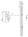
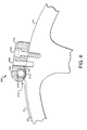
- An example of a scanning system 30 is illustrated in Fig. 2.
- the scanning system 30 is displaced by the movable carriage 32 in a slow scan axial direction (directional arrow A) along the length of the rotating external drum 24 to expose the printing plate 18 in a line-wise manner when a single beam is used or in a section-wise manner for multiple beams.
- Other types of imaging systems may also be used in the present invention.
- the external drum 24 is rotated by a drive system 38 in a clockwise or counterclockwise direction as indicated by directional arrow B.
- the drive system 38 rotates the external drum 24 at a rate of about 100-1000 rpm.
- the scanning system 30 includes a system 40 for generating the imaging beam or beams 36.
- the system 40 comprises a light or radiation source 42 for producing the imaging beam or beams 36 (illustrated for simplicity as a single beam), and an optical system 44 positioned between the radiation source 42 and the media support surface 28 for focusing the imaging beam or beams 36 onto the printing plate 18. It should be noted, however, that the system 40 described above is only one of many possible different types of scanning systems that may be used to record image data on the printing plate 18.
- the leading edge 46 of the printing plate 18 is held in position against the media support surface 28 of the external drum 24 by a leading edge clamping mechanism 48.
- the trailing edge 50 of the printing plate 18 is held in position against the media support surface 28 of the external drum 24 by a trailing edge clamping mechanism 52.
- a vacuum clamping bar or magnetic clamps may be used to implement the trailing edge clamping system 52.
- Many other known systems may also be used to clamp the trailing edge 50 of printing plate 18 against the media support surface 28 of the external drum 24.
- leading edge clamping mechanism 48 and the trailing edge clamping mechanism 52 both provide a tangential friction force between the printing plate 18 and the media support surface 28 of the external drum 24 that is sufficient to resist the tendency of the edges of the printing plate 18 to pull out of the clamping mechanisms 48, 52, at a high drum rotational speed.
- a vacuum source 54 may be used to draw a vacuum through an arrangement of ports and vacuum grooves 56 (Fig. 2) to hold the printing plate 18 against the media support surface 28 of the external drum 24.
- the vacuum source 54 may also supply a vacuum to the autoloading system 26 that is configured to remove or "pick" the top printing plate 18 from the stack 20 of printing plates.
- a registration system comprising, for example, a set of registration pins on the external drum 24, and a plate edge detection system (not shown), may be used to accurately and repeatably position and locate each printing plate 18 on the external drum 24.
- Fig. 3-6 illustrate a first embodiment of a leading edge clamping mechanism 100 in accordance with the present invention.
- the leading edge clamping mechanism 100 is mounted on the external drum 24 and extends axially across a substantial portion of the width of the drum 24.
- the length of the leading edge clamping mechanism 100 is greater than the width of the largest printing plate 18 that may be imaged on the external drum 24.
- the specific location for the mounting of the leading edge clamping mechanism 100 on the external drum 24 is set using a fixture (not shown) attached to the external drum 24.
- the leading edge clamping mechanism 100 includes a mounting portion 102 and a clamping portion 104. As shown in greater detail in Fig. 4-6, the mounting portion 102 of the leading edge clamping mechanism 100 is secured to the external drum 24 using bolts 106 or other suitable mounting hardware.
- the mounting portion 102 may comprise one or more distinct sections (e.g., 102a, 102b, Fig. 3).
- the clamping portion 104 of the leading edge clamping mechanism 100 includes one or more spring segments 108.
- the spring segments 108 are formed using a lightweight spring steel or other suitable material. The use of a lightweight material lessens the possibility of distortion of the spring segments 108 due to centrifugal forces during imaging.
- Fig.4 when the leading edge clamping mechanism 100 is secured to the external drum 24, the distal end 110 of each spring segment 108 of the clamping portion 104 is biased against the surface of the external drum 24 as indicated by directional arrow C.
- the biasing force provided by the spring segments 108 must be sufficient to hold the leading edge 46 of the printing plate 18 against the media support surface 28 of the external drum 24 as the external drum 24 is rotated at high speed during imaging.
- the magnitude of the biasing force is application specific and depends on many factors including the rotational speed of the external drum 24 during imaging, the type of printing plate 18 being imaged (e.g., aluminum or polyester substrate), etc.
- each spring segment 108 of the clamping portion 104 of the leading edge clamping mechanism 100 may be formed as a single, continuous unit or may be configured to include a plurality of fingers 112.
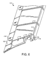
- the fingers 112 may be provided by forming slots 114 in the spring segments 108. As shown in Fig. 3 and 4, the slots 114 may extend to the edge 116 of the distal end 110 of the spring segments 108, in which case the plurality of fingers 112 operate independently of one another, or, as shown in Fig. 6, the slots 114 may extend partially through the distal end 110 of the spring segments 108.
- These types of finger arrangement may, depending upon the specific configuration of the spring segments 108, provide more uniform loading on the external drum 24.
- the leading edge clamping mechanism 100 is actuated using a pneumatic bladder 118.
- the pneumatic bladder 118 may be formed from an elastomer such as EPDM, silicone, neoprene, etc.
- the pneumatic bladder 210 (Fig. 7 and 8) and inflatable seal clamp 304 (Fig. 9) described below may also be formed from similar elastomeric materials.
- the pneumatic bladder 118 extends under the spring segments 108 of the clamping portion 104 of the leading edge clamping mechanism 100, and is constrained between the external drum 24 and the underside 120 of the spring segments 108 by a support wall 122.
- Compressed air is provided via tube 124 (Fig. 3) to the pneumatic bladder 118 by a compressed air source 126 through a rotary coupling 128 in the shaft 130 of the external drum 24.
- a pressure relief valve 132 may be provided to prevent over-inflation of the pneumatic bladder 118.
- the pneumatic bladder 118 expands when it is supplied with compressed air from the compressed air source 126. Since lateral expansion of the pneumatic bladder 118 is limited by the support wall 122, the pneumatic bladder 118 necessarily expands toward the underside 120 of the spring segments 108. This forces the edge 116 of the distal end 110 of the spring segments 108 away from the surface of the external drum 24 as indicated by directional arrow D. This creates a space 134 through which the leading end 46 of a printing plate 18 may be inserted into, or removed from, the leading edge clamping mechanism 100.
- the bladder 118 When the compressed air is released from the pneumatic bladder 118, the bladder 118 deflates and the edge 116 of the distal end 110 of the spring segments 108 is forced against the surface of the external drum 24. This clamps the leading edge 46 of printing plate 18 against the surface of the external drum 24 as shown in Fig. 4.
- the edge 116 of the distal end 110 of the spring segments 108 may be flat as shown or may be rounded. Other suitable shapes are also possible.
- the compressed air may be released from the pneumatic bladder 118 using a valve 136 ( Fig. 3 e.g., a three-way solenoid valve) or other suitable air release system.
- a valve 136 Fig. 3 e.g., a three-way solenoid valve
- a similar system may also be used to release air from the pneumatic bladder 210 (Fig. 7-8) and inflatable seal clamp 304 (Fig. 9) described below.
- a plurality of registration pins 138 are mounted to the external drum 24 by bolts 140 or other suitable mounting hardware, and are positioned under the spring segments 108 between the support wall 122 and the distal end 110 of the segments 108.
- the registration pins 138 are used to accurately and repeatedly position (i.e., "register") the printing plate 18 on the external drum 24 for clamping and subsequent imaging.
- the leading edge clamping mechanism 200 includes a body 202 that is mounted to the external drum 24 using mounting hardware 204, and a plurality of registration pins 206 for registering a printing plate 18 on the external drum 24. Although shown in cross-section in Fig. 7 and 8, it should be realized that the leading edge clamping mechanism 200 extends across a substantial portion of the width of the external drum 24, much like the leading edge clamping mechanism 100 shown in Fig. 3.
- the body 202 of the leading edge clamping mechanism 200 includes a channel 208 that contains and constrains a pneumatic bladder 210.
- a flexible shield 212 formed of plastic, metal, or other suitable material, is affixed to the body 202 adjacent the channel 208.
- the pneumatic bladder 210 When the pneumatic bladder 210 is not filled with compressed air, as shown in Fig. 7, the flexible shield 212 is in a retracted state, whereby the leading edge 46 of a printing plate 18 may be inserted into, or removed from, the mouth 214 of the leading edge clamping mechanism 200. It should also be noted that the flexible shield 212 helps to guide the leading edge 46 of the printing plate 18 into the mouth 214 of the leading edge clamping mechanism 200.
- the pneumatic bladder 210 When the pneumatic bladder 210 is inflated with compressed air (e.g., using a compressed air source 126, Fig. 3), the bladder 210 expands and forces the flexible shield 212 toward the external drum 24.
- the flexible shield 212 clamps the leading edge 46 of the printing plate 18 against the surface of the external drum 24. Because a pneumatic bladder 210 is used to apply the clamping force against the printing plate 18, the leading edge clamping mechanism 200 self-adjusts for plate thickness.
- the force applied against the leading edge 46 of the printing plate 18 by pneumatic bladder 210/flexible shield 212 must be sufficient to hold the leading edge 46 against the media support surface 28 of the external drum 24 as the external drum 24 is rotated at high speed during imaging. As described with regard to the leading edge clamping mechanism 100 in Fig. 3-6, the magnitude of this force is application specific.
- the flexible shield 212 also protects the pneumatic bladder 210 from plate damage.
- the flexible shield 212 prevents the often sharp edges of the printing plate 18 from coming into contact with the pneumatic bladder 210.
- the dimensions of the flexible shield 212 are chosen to prevent any contact between the printing plate 18 and the pneumatic bladder 210.
- Fig. 9 illustrates another embodiment of a leading edge clamping mechanism 300 in accordance with the present invention.
- the leading edge clamping mechanism 300 includes a groove 302 for receiving the leading edge 46 of a printing plate 18 and an inflatable seal clamp 304 for clamping the leading edge 46 of the printing plate 18 against a side 306 of the groove 302. As with the leading edge clamping mechanisms 100 (Fig. 3-6), 200 (Fig. 7-8), the leading edge clamping mechanism 300 extends across a substantial portion of the width of the external drum 24.
- the inflatable seal clamp 304 includes an inflatable portion 308 and a base portion 310.
- the base portion 310 is mounted within a slot 312 formed in a bar 314.
- the bar 314 is positioned within a groove 316 that has been formed (e.g., machined) in the external drum 24.
- the inflatable seal clamp 304 is normally in a deflated (i.e., "retracted") state. This allows the leading edge 46 of the printing plate 18 to be displaced into, or removed from, the groove 302 of the leading edge clamping mechanism 300 without contacting the inflatable seal clamp 304.
- the rear wall 318 of the groove 302 is used to register the printing plate 18 on the external drum 24 for clamping and subsequent imaging.
- the inflatable portion 308 of the inflatable seal clamp 304 is inflated (e.g., using a compressed air source 126, Fig. 3). This clamps the leading edge 46 of the printing plate 18 against the side 306 of the groove 302. Because an inflatable seal clamp 304 is used to apply the clamping force against the printing plate 18, the leading edge clamping mechanism 300 self-adjusts for plate thickness.
- the force applied against the leading edge 46 of the printing plate 18 by inflatable seal clamp 304 must be sufficient to hold the leading edge 46 in position within the groove 302 as the external drum 24 is rotated at high speed during imaging.
- the magnitude of this force is application specific, and may depend on a force on the leading edge 46 of the printing plate 18, exerted by the inflatable seal clamp 304 or the resilient means, coupled to the external drum 24, such as the spring segment 108 (Fig. 3-5) or the flexible shield 212 (Fig. 7-8).
Landscapes
- Engineering & Computer Science (AREA)
- Multimedia (AREA)
- Signal Processing (AREA)
- Mechanical Engineering (AREA)
- Manufacturing & Machinery (AREA)
- Exposure And Positioning Against Photoresist Photosensitive Materials (AREA)
- Supply, Installation And Extraction Of Printed Sheets Or Plates (AREA)
- Handling Of Cut Paper (AREA)
- Facsimile Scanning Arrangements (AREA)
Abstract
Description
- The present invention is in the field of imaging systems. More particularly, the present invention provides an apparatus and method for clamping the leading edge of a recording media, such as a printing plate, on the external drum of an imaging system.
- In external drum imaging systems, a movable optical carriage is commonly used to displace an image recording source in a slow scan direction while a cylindrical drum, having recording media mounted on an external surface thereof, is rotated with respect to the image recording source. The drum rotation causes the recording media to advance past the image recording source along a fast scan direction that is substantially perpendicular to the slow scan direction.
- The image recording source may include an optical system for generating one or more imaging beams that are scanned across the surface of the recording media. Each imaging beam may be separately modulated according to a digital information signal representing data corresponding to the image to be recorded.
- The recording media to be imaged by an external drum imaging system is commonly supplied in discrete, flexible sheets, hereinafter collectively referred to as "printing plates". Each printing plate may comprise one or more layers supported by a support substrate, which for many printing plates is a plano-graphic aluminum sheet. Other layers may include one or more image recording (i.e., "imageable") layers such as a photosensitive, radiation sensitive, or thermally sensitive layer, or other chemically or physically alterable layers. Printing plates that are supported by a polyester support substrate are also known and can be used in the present invention. Printing plates are available in a wide variety of sizes, typically ranging, e.g., from 229 mm x 305 mm (9" x 12"), or smaller, to 1473 mm x 2032 mm (58" x 80"), or larger.
- Many clamping systems are available for holding the leading edge of a printing plate on the external drum of an imaging system. One example of a leading edge clamping mechanism is disclosed in U.S. Patent No. 6,412,413. Although the leading edge clamping mechanism disclosed in this reference is highly effective, it has several drawbacks. For example, the leading edge clamping mechanism uses a fixed actuator to selectively open and close a clamping portion. As such, the clamping portion can only be opened and closed when it is positioned at a single circumferential position of the external drum (i.e., under the fixed actuator). Further, the leading edge clamping mechanism is a fairly complex mechanical assembly that has a high part count and is expensive to produce.
- The above-mentioned problems are solved by a system having the specific features set out in claim 1 and a method according to
claim 12. Specific features for preferred embodiments of the invention are set out in the dependent claims. - The present invention provides an apparatus and method for clamping the leading edge of a printing plate on the external drum of an imaging system.
- Generally, the present invention provides an apparatus, with a spring segment disposed on the external drum, wherein the spring segment may be selectively displaced between a clamping position for clamping the leading edge of the printing plate against the external drum and a release position; and an inflatable member positioned between the spring segment and the external drum for displacing the spring segment between the clamping position and the release position.
- The present invention further provides a method including: selectively displacing a spring segment between a clamping position for clamping the leading edge of the printing plate against the external drum and a release position; and displacing the spring segment between the clamping position and the release position using an inflatable member positioned between the spring segment and the external drum.
- The present invention additionally provides an imaging system with an external drum for supporting a printing plate; a system for recording image data onto the printing plate; and a leading edge clamping apparatus for clamping a leading end of the printing plate on the external drum, the leading edge clamping apparatus including a spring segment disposed on the external drum, wherein the spring segment may be selectively displaced between a clamping position for clamping the leading edge of the printing plate against the external drum and a release position; and an inflatable member positioned between the spring segment and the external drum for displacing the spring segment between the clamping position and the release position.
- The present invention further includes a leading edge clamping apparatus for clamping a leading end of a printing plate on an external drum of an imaging system, with an inflatable member; and a shield that may be selectively displaced by the inflatable member between a clamping position for clamping the leading edge of the printing plate against the external drum and a release position.
- The present invention also provides a leading edge clamping apparatus for clamping a leading end of a printing plate on an external drum of an imaging system, having a groove formed in the external drum, wherein a wall of the groove serves to register the leading edge of the printing plate on the external drum; and an inflatable clamp positioned in the external drum adjacent a side of the groove, wherein the inflatable clamp may be selectively displaced between an inflated, clamping position for clamping the leading edge of the printing plate to the external drum and a deflated, release position.
- The present invention further provides a leading edge clamping apparatus for clamping a leading end of a printing plate on an external drum of an imaging system, with an inflatable member positioned between a spring segment and the external drum for displacing the spring segment between a clamping position and a release position.
- Further embodiments and advantages of the present invention will become apparent from the following description and drawings.
- The features of the present invention will best be understood from a detailed description of the invention and embodiments thereof selected for the purpose of illustration and shown in the accompanying drawings in which:
- Fig. 1 illustrates an external drum imaging system for recording images onto a printing plate.
- Fig. 2 illustrates an example of an imaging system including a movable optical carriage and scanning system, usable in the external drum imaging system of Fig. 1.
- Fig. 3 is a perspective, partial, cut-away view of an external drum including a leading edge clamping mechanism in accordance with a first embodiment of the present invention.
- Fig. 4 is a cross-sectional view of the leading edge clamping mechanism of Fig. 3 in a plate clamping position.
- Fig. 5 is a cross-sectional view of the leading edge clamping mechanism of Fig. 3 in a plate release position.
- Fig. 6 is a perspective cross-sectional view of the leading edge clamping mechanism of Fig. 3.
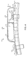
- Fig. 7 is a cross-sectional view of a leading edge clamping mechanism in plate release position in accordance with another embodiment of the present invention.
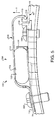
- Fig. 8 is cross-sectional view of the leading edge clamping mechanism of Fig. 7 in a plate clamping position.
- Fig. 9 is a perspective cross-sectional view of a leading edge clamping mechanism in accordance with another embodiment of the present invention.
-
- The features of the present invention are illustrated in detail in the accompanying drawings, wherein like reference numerals refer to like elements throughout the drawings. Although the drawings are intended to illustrate the present invention, the drawings are not necessarily drawn to scale.
- An example of an external
drum imaging system 10 is illustrated in Fig. 1. In this example, theimaging system 10 comprises an external drum platesetter configured to record digital data onto aprinting plate 18. Although described below with regard to an external drum platesetter, the clamping apparatus and method of the present invention may be used in conjunction with a wide variety of other types of external drum, internal drum, or flatbed imaging systems, including imagesetters and the like, without departing from the intended scope of the present invention. Further, the clamping apparatus and method of the present invention may be used to clamp an unexposed printing plate on the plate cylinder of a printing press having an "on-press" imaging system. In its broadest sense, the clamping apparatus and method of the present invention may be used to clamp a sheet-like material to any type of cylindrical drum. - The
imaging system 10 generally includes a front end computer orworkstation 12 for the design, layout, editing, and/or processing of digital files representing pages to be printed, a raster image processor (RIP) 14 for processing the digital pages to provide rasterized page data (e.g., rasterized digital files) for driving an image recorder, and an image recorder or engine, such as anexternal drum platesetter 16, for recording the rasterized digital files onto aprinting plate 18. - A
stack 20 ofprinting plates 18 is commonly supplied in acassette 22. Aprinting plate 18 is picked off of thestack 20 and subsequently mounted on anexternal drum 24 of theexternal drum platesetter 16 by anautoloading system 26. - The
external drum platesetter 16 includes anexternal drum 24 having a cylindricalmedia support surface 28 for supporting aprinting plate 18 during imaging. Theexternal drum platesetter 16 further includes ascanning system 30, coupled to amovable carriage 32, for recording digital data onto theimaging surface 34 of theprinting plate 18 using a single ormultiple imaging beams 36. An example of ascanning system 30 is illustrated in Fig. 2. In particular, thescanning system 30 is displaced by themovable carriage 32 in a slow scan axial direction (directional arrow A) along the length of the rotatingexternal drum 24 to expose theprinting plate 18 in a line-wise manner when a single beam is used or in a section-wise manner for multiple beams. Other types of imaging systems may also be used in the present invention. - As shown in Fig. 1 the
external drum 24 is rotated by adrive system 38 in a clockwise or counterclockwise direction as indicated by directional arrow B. Typically, thedrive system 38 rotates theexternal drum 24 at a rate of about 100-1000 rpm. As further illustrated in Fig. 2, thescanning system 30 includes a system 40 for generating the imaging beam orbeams 36. The system 40 comprises a light orradiation source 42 for producing the imaging beam or beams 36 (illustrated for simplicity as a single beam), and anoptical system 44 positioned between theradiation source 42 and themedia support surface 28 for focusing the imaging beam orbeams 36 onto theprinting plate 18. It should be noted, however, that the system 40 described above is only one of many possible different types of scanning systems that may be used to record image data on theprinting plate 18. - In the external
drum imaging system 10 shown in Fig. 1, the leadingedge 46 of theprinting plate 18 is held in position against themedia support surface 28 of theexternal drum 24 by a leadingedge clamping mechanism 48. Similarly, thetrailing edge 50 of theprinting plate 18 is held in position against themedia support surface 28 of theexternal drum 24 by a trailingedge clamping mechanism 52. As detailed in U.S. Patent No. 6,412,413, a vacuum clamping bar or magnetic clamps may be used to implement the trailingedge clamping system 52. Many other known systems may also be used to clamp the trailingedge 50 ofprinting plate 18 against themedia support surface 28 of theexternal drum 24. The leadingedge clamping mechanism 48 and the trailingedge clamping mechanism 52 both provide a tangential friction force between theprinting plate 18 and themedia support surface 28 of theexternal drum 24 that is sufficient to resist the tendency of the edges of theprinting plate 18 to pull out of the clampingmechanisms - A vacuum source 54 (Fig. 1) may be used to draw a vacuum through an arrangement of ports and vacuum grooves 56 (Fig. 2) to hold the
printing plate 18 against themedia support surface 28 of theexternal drum 24. The vacuum source 54 (Fig. 1) may also supply a vacuum to the autoloadingsystem 26 that is configured to remove or "pick" thetop printing plate 18 from thestack 20 of printing plates. A registration system comprising, for example, a set of registration pins on theexternal drum 24, and a plate edge detection system (not shown), may be used to accurately and repeatably position and locate eachprinting plate 18 on theexternal drum 24. - Fig. 3-6 illustrate a first embodiment of a leading
edge clamping mechanism 100 in accordance with the present invention. - As shown in Fig. 3, the leading
edge clamping mechanism 100 is mounted on theexternal drum 24 and extends axially across a substantial portion of the width of thedrum 24. The length of the leadingedge clamping mechanism 100 is greater than the width of thelargest printing plate 18 that may be imaged on theexternal drum 24. The specific location for the mounting of the leadingedge clamping mechanism 100 on theexternal drum 24 is set using a fixture (not shown) attached to theexternal drum 24. - The leading
edge clamping mechanism 100 includes a mountingportion 102 and a clampingportion 104. As shown in greater detail in Fig. 4-6, the mountingportion 102 of the leadingedge clamping mechanism 100 is secured to theexternal drum 24 usingbolts 106 or other suitable mounting hardware. The mountingportion 102 may comprise one or more distinct sections (e.g., 102a, 102b, Fig. 3). - The clamping
portion 104 of the leadingedge clamping mechanism 100 includes one ormore spring segments 108. Thespring segments 108 are formed using a lightweight spring steel or other suitable material. The use of a lightweight material lessens the possibility of distortion of thespring segments 108 due to centrifugal forces during imaging. As shown in Fig.4 when the leadingedge clamping mechanism 100 is secured to theexternal drum 24, thedistal end 110 of eachspring segment 108 of the clampingportion 104 is biased against the surface of theexternal drum 24 as indicated by directional arrow C. The biasing force provided by thespring segments 108 must be sufficient to hold theleading edge 46 of theprinting plate 18 against themedia support surface 28 of theexternal drum 24 as theexternal drum 24 is rotated at high speed during imaging. The magnitude of the biasing force is application specific and depends on many factors including the rotational speed of theexternal drum 24 during imaging, the type ofprinting plate 18 being imaged (e.g., aluminum or polyester substrate), etc. - As shown in Fig. 3 each
spring segment 108 of the clampingportion 104 of the leadingedge clamping mechanism 100 may be formed as a single, continuous unit or may be configured to include a plurality offingers 112. Thefingers 112 may be provided by formingslots 114 in thespring segments 108. As shown in Fig. 3 and 4, theslots 114 may extend to theedge 116 of thedistal end 110 of thespring segments 108, in which case the plurality offingers 112 operate independently of one another, or, as shown in Fig. 6, theslots 114 may extend partially through thedistal end 110 of thespring segments 108. These types of finger arrangement may, depending upon the specific configuration of thespring segments 108, provide more uniform loading on theexternal drum 24. - The leading
edge clamping mechanism 100 is actuated using apneumatic bladder 118. Thepneumatic bladder 118 may be formed from an elastomer such as EPDM, silicone, neoprene, etc. The pneumatic bladder 210 (Fig. 7 and 8) and inflatable seal clamp 304 (Fig. 9) described below may also be formed from similar elastomeric materials. As shown in Fig. 4 thepneumatic bladder 118 extends under thespring segments 108 of the clampingportion 104 of the leadingedge clamping mechanism 100, and is constrained between theexternal drum 24 and theunderside 120 of thespring segments 108 by asupport wall 122. Compressed air is provided via tube 124 (Fig. 3) to thepneumatic bladder 118 by acompressed air source 126 through arotary coupling 128 in theshaft 130 of theexternal drum 24. Apressure relief valve 132 may be provided to prevent over-inflation of thepneumatic bladder 118. - As shown in Fig. 5, the
pneumatic bladder 118 expands when it is supplied with compressed air from the compressedair source 126. Since lateral expansion of thepneumatic bladder 118 is limited by thesupport wall 122, thepneumatic bladder 118 necessarily expands toward theunderside 120 of thespring segments 108. This forces theedge 116 of thedistal end 110 of thespring segments 108 away from the surface of theexternal drum 24 as indicated by directional arrow D. This creates aspace 134 through which theleading end 46 of aprinting plate 18 may be inserted into, or removed from, the leadingedge clamping mechanism 100. When the compressed air is released from thepneumatic bladder 118, thebladder 118 deflates and theedge 116 of thedistal end 110 of thespring segments 108 is forced against the surface of theexternal drum 24. This clamps the leadingedge 46 ofprinting plate 18 against the surface of theexternal drum 24 as shown in Fig. 4. Theedge 116 of thedistal end 110 of thespring segments 108 may be flat as shown or may be rounded. Other suitable shapes are also possible. - The compressed air may be released from the
pneumatic bladder 118 using a valve 136 ( Fig. 3 e.g., a three-way solenoid valve) or other suitable air release system. A similar system may also be used to release air from the pneumatic bladder 210 (Fig. 7-8) and inflatable seal clamp 304 (Fig. 9) described below. - As shown in Fig. 4-5, a plurality of registration pins 138 are mounted to the
external drum 24 bybolts 140 or other suitable mounting hardware, and are positioned under thespring segments 108 between thesupport wall 122 and thedistal end 110 of thesegments 108. The registration pins 138 are used to accurately and repeatedly position (i.e., "register") theprinting plate 18 on theexternal drum 24 for clamping and subsequent imaging. - Another embodiment of a leading
edge clamping mechanism 200 in accordance with the present invention is illustrated in Fig. 7 and 8. The leadingedge clamping mechanism 200 includes abody 202 that is mounted to theexternal drum 24 using mountinghardware 204, and a plurality ofregistration pins 206 for registering aprinting plate 18 on theexternal drum 24. Although shown in cross-section in Fig. 7 and 8, it should be realized that the leadingedge clamping mechanism 200 extends across a substantial portion of the width of theexternal drum 24, much like the leadingedge clamping mechanism 100 shown in Fig. 3. Thebody 202 of the leadingedge clamping mechanism 200 includes achannel 208 that contains and constrains apneumatic bladder 210. Aflexible shield 212, formed of plastic, metal, or other suitable material, is affixed to thebody 202 adjacent thechannel 208. When thepneumatic bladder 210 is not filled with compressed air, as shown in Fig. 7, theflexible shield 212 is in a retracted state, whereby the leadingedge 46 of aprinting plate 18 may be inserted into, or removed from, themouth 214 of the leadingedge clamping mechanism 200. It should also be noted that theflexible shield 212 helps to guide theleading edge 46 of theprinting plate 18 into themouth 214 of the leadingedge clamping mechanism 200. When thepneumatic bladder 210 is inflated with compressed air (e.g., using acompressed air source 126, Fig. 3), thebladder 210 expands and forces theflexible shield 212 toward theexternal drum 24. As shown in Fig. 8, theflexible shield 212 clamps the leadingedge 46 of theprinting plate 18 against the surface of theexternal drum 24. Because apneumatic bladder 210 is used to apply the clamping force against theprinting plate 18, the leadingedge clamping mechanism 200 self-adjusts for plate thickness. - The force applied against the leading
edge 46 of theprinting plate 18 bypneumatic bladder 210/flexible shield 212 must be sufficient to hold theleading edge 46 against themedia support surface 28 of theexternal drum 24 as theexternal drum 24 is rotated at high speed during imaging. As described with regard to the leadingedge clamping mechanism 100 in Fig. 3-6, the magnitude of this force is application specific. - The
flexible shield 212 also protects thepneumatic bladder 210 from plate damage. In particular, theflexible shield 212 prevents the often sharp edges of theprinting plate 18 from coming into contact with thepneumatic bladder 210. To this end, the dimensions of theflexible shield 212 are chosen to prevent any contact between theprinting plate 18 and thepneumatic bladder 210. - Fig. 9 illustrates another embodiment of a leading
edge clamping mechanism 300 in accordance with the present invention. - The leading
edge clamping mechanism 300 includes agroove 302 for receiving the leadingedge 46 of aprinting plate 18 and aninflatable seal clamp 304 for clamping the leadingedge 46 of theprinting plate 18 against aside 306 of thegroove 302. As with the leading edge clamping mechanisms 100 (Fig. 3-6), 200 (Fig. 7-8), the leadingedge clamping mechanism 300 extends across a substantial portion of the width of theexternal drum 24. - The
inflatable seal clamp 304 includes aninflatable portion 308 and abase portion 310. Thebase portion 310 is mounted within aslot 312 formed in abar 314. Thebar 314 is positioned within agroove 316 that has been formed (e.g., machined) in theexternal drum 24. Theinflatable seal clamp 304 is normally in a deflated (i.e., "retracted") state. This allows the leadingedge 46 of theprinting plate 18 to be displaced into, or removed from, thegroove 302 of the leadingedge clamping mechanism 300 without contacting theinflatable seal clamp 304. Therear wall 318 of thegroove 302 is used to register theprinting plate 18 on theexternal drum 24 for clamping and subsequent imaging. With theprinting plate 18 properly engaged within thegroove 302, theinflatable portion 308 of theinflatable seal clamp 304 is inflated (e.g., using acompressed air source 126, Fig. 3). This clamps the leadingedge 46 of theprinting plate 18 against theside 306 of thegroove 302. Because aninflatable seal clamp 304 is used to apply the clamping force against theprinting plate 18, the leadingedge clamping mechanism 300 self-adjusts for plate thickness. - The force applied against the leading
edge 46 of theprinting plate 18 byinflatable seal clamp 304 must be sufficient to hold theleading edge 46 in position within thegroove 302 as theexternal drum 24 is rotated at high speed during imaging. As described with regard to the leadingedge clamping mechanisms edge 46 of theprinting plate 18, exerted by theinflatable seal clamp 304 or the resilient means, coupled to theexternal drum 24, such as the spring segment 108 (Fig. 3-5) or the flexible shield 212 (Fig. 7-8). - The foregoing description of the present invention has been presented for purposes of illustration and description. It is not intended to be exhaustive or to limit the invention to the precise form disclosed, and many modifications and variations are possible in light of the above teaching. Such modifications and variations that may be apparent to a person skilled in the art may be included within the scope of this invention.
Claims (12)
- An imaging system (10) comprising:is characterised by an inflatable member (118, 210, 308) for displacing the clamp (108, 212, 304) between the clamping position (Fig. 4, 8) and the release position (Fig. 5, 7).an external drum (24) for supporting a printing plate (18);a system (30) for recording image data onto said printing plate (18) ;a clamp (108, 212, 304), for clamping a leading edge (46) of said printing plate (18) on said external drum (24), coupled to the external drum (24) and being selectively displaceable between:a clamping position (Fig. 4, 8) for clamping said leading edge (46) against said external drum (24) ; and,a release position (Fig. 5, 7) ;
- The imaging system (10) according to claim 1, wherein:said clamp is a spring segment (108), preferably having a plurality of fingers (112), on the external drum (24) ; and,said inflatable member (118) is between said spring segment (108) and said external drum (24).
- The imaging system (10) according to claim 2, further comprising:means for inflating (126) the inflatable member (118) for displacing the spring segment (108) from the clamping position (Fig. 4) to the release position (Fig. 5) ; and,means for deflating (136) the inflatable member (118) for displacing the spring segment (108) from the release position (Fig. 5) to the clamping position (Fig. 4).
- The imaging system (10) according to any one of claims 2 to 3, further comprising a support wall (122) for constraining the inflatable member (118) between the external drum (24) and the spring segment (108), and for limiting lateral expansion of the inflatable member (118).
- The imaging system (10) according to any one of claims 2 to 4, further comprising a registration system (138), between said spring segment (108) and said external drum (24), for registering the printing plate (18) on the external drum (24).
- The imaging system (10) according to any one of claims 2 to 5, wherein a first end of the spring segment (108) is secured to the external drum (24), and wherein a second end of the spring segment (108) is free to move selectively:toward the external drum (24) upon a deflation of the inflatable member (118) ; and,away from the external drum (24) upon an inflation of the inflatable member (118).
- The imaging system (10) according to claim 1, wherein said clamp is a shield (212) and said system (10) further comprises:means for inflating (126) the inflatable member (210) for displacing the shield (212) from the release position (Fig. 7) to the clamping position (Fig. 8) ; and,means for deflating (136) the inflatable member (210) for displacing the shield (212) from the clamping position (Fig. 8) to the release position (Fig. 7).
- The imaging system (10) according to claim 7, wherein said external drum (24) includes a body (202), having a channel (208) for holding the inflatable member (210).
- The imaging system (10) according to claim 8, wherein the shield (212) is coupled to the body (202) and extends between the inflatable member (210) and the external drum (24) for preventing the printing plate (18) from contacting the inflatable member (210).
- The imaging system (10) according to claim 1, wherein:the external drum (24) has a groove (302) ;said clamp (304) is inflatable and positioned in the external drum (24), adjacent a side (306) of said groove (302) ; and,said inflatable clamp (304) is inflated in the clamping position and deflated in the release position.
- The imaging system (10) according to any one of the previous claims, further comprising a registration system (138, 206, 318), preferably having a plurality of registration pins (138, 206), for registering the printing plate (18) on the external drum (24) .
- A method for clamping a leading edge (46) of a printing plate (18) on an external drum (24) of an imaging system (10), comprising selectively displacing a clamp (108, 212, 304) between:is characterised by displacing said clamp (108, 212, 304) between the clamping position (Fig. 4, 8) and the release position (Fig. 5, 7) using an inflatable member (118, 210, 308).a clamping position (Fig. 4, 8) for clamping said leading edge (46) against said external drum (24) ; and,a release position (Fig. 5, 7);
Applications Claiming Priority (2)
| Application Number | Priority Date | Filing Date | Title |
|---|---|---|---|
| US230584 | 2002-08-29 | ||
| US10/230,584 US6705226B1 (en) | 2002-08-29 | 2002-08-29 | Media clamping apparatus and method for an external drum imaging system |
Publications (2)
| Publication Number | Publication Date |
|---|---|
| EP1408680A2 true EP1408680A2 (en) | 2004-04-14 |
| EP1408680A3 EP1408680A3 (en) | 2006-06-28 |
Family
ID=31946353
Family Applications (1)
| Application Number | Title | Priority Date | Filing Date |
|---|---|---|---|
| EP03102674A Withdrawn EP1408680A3 (en) | 2002-08-29 | 2003-08-29 | Media clamping apparatus and method for an external drum imaging system. |
Country Status (3)
| Country | Link |
|---|---|
| US (1) | US6705226B1 (en) |
| EP (1) | EP1408680A3 (en) |
| JP (1) | JP2004096748A (en) |
Cited By (1)
| Publication number | Priority date | Publication date | Assignee | Title |
|---|---|---|---|---|
| EP1591243A3 (en) * | 2004-04-28 | 2008-02-27 | Heidelberger Druckmaschinen Aktiengesellschaft | Device for clamping and holding a printing plate on an exposure drum |
Families Citing this family (8)
| Publication number | Priority date | Publication date | Assignee | Title |
|---|---|---|---|---|
| JP3866214B2 (en) * | 2003-03-31 | 2007-01-10 | 株式会社東芝 | Photosensitive device and image forming apparatus |
| US7165492B2 (en) * | 2005-02-07 | 2007-01-23 | Esko-Graphics A/S | Method and apparatus to clamp and release flexible plates onto an imaging cylinder |
| US6994027B1 (en) | 2005-03-03 | 2006-02-07 | Agfa Corporation | Device and method to prevent movement of a printing plate during clamping |
| US8100054B2 (en) * | 2006-08-25 | 2012-01-24 | Esko-Graphics Imaging Gmbh | Clamping device, system and method for clamping flexible plates onto an imaging cylinder |
| WO2010011875A2 (en) | 2008-07-24 | 2010-01-28 | The Regents Of The University Of California | Apparatus and method for dispersive fourier-transform imaging |
| DE102016205769A1 (en) * | 2015-05-06 | 2016-11-10 | Heidelberger Druckmaschinen Ag | Sheet transport drum and printing machine with such a sheet transport drum |
| CN114732525B (en) * | 2022-05-06 | 2024-09-10 | 河北工业大学 | Pneumatic humanoid finger vascular intervention tube wire safe clamping continuous delivery mechanism |
| CN115519835B (en) * | 2022-09-21 | 2023-06-27 | 浙江京华激光科技股份有限公司 | Preparation device and preparation method of double-sided anti-counterfeiting amplifying film |
Citations (2)
| Publication number | Priority date | Publication date | Assignee | Title |
|---|---|---|---|---|
| US20010024014A1 (en) * | 2000-03-23 | 2001-09-27 | Takao Ozaki | Sheet material fixing device |
| US6412413B1 (en) | 2000-02-25 | 2002-07-02 | Agfa Corporation | Media clamp for external drum imaging system |
Family Cites Families (14)
| Publication number | Priority date | Publication date | Assignee | Title |
|---|---|---|---|---|
| US3058417A (en) | 1959-05-22 | 1962-10-16 | Nils H V Norlin | Mechanism for clamping plates to the cylinders of printing machines |
| US3715981A (en) | 1970-06-29 | 1973-02-13 | Hamilton Tool Co | Fluid actuator and lock for printing plate cylinders |
| US3769868A (en) | 1971-04-19 | 1973-11-06 | Strucker O Kg | Transverse cutting machine |
| US4660825A (en) | 1979-07-26 | 1987-04-28 | Ricoh Company Ltd. | Sheet clamping device |
| DE3731039A1 (en) | 1987-09-16 | 1989-03-30 | Koenig & Bauer Ag | DEVICE FOR CLAMPING FLEXIBLE PRINT PLATES ON THE PLATE CYLINDER OF A ROTARY PRINTING MACHINE |
| ES2080879T3 (en) | 1990-12-21 | 1996-02-16 | Heidelberger Druckmasch Ag | QUICK FASTENING DEVICE. |
| DE4200406C2 (en) * | 1992-01-10 | 1996-10-10 | Heidelberger Druckmasch Ag | Gripper device on sheet-fed rotary printing machines |
| DE9317726U1 (en) | 1992-12-24 | 1994-02-03 | Koenig & Bauer AG, 97080 Würzburg | spindle |
| US5335046A (en) | 1993-02-22 | 1994-08-02 | Intergraph Corporation | Clamping mechanism for use on a rotatable plotter drum |
| US5518231A (en) | 1993-04-19 | 1996-05-21 | Xerox Corporation | Self adjusting sheet gripping apparatus |
| DE4401201C2 (en) | 1994-01-18 | 1996-08-01 | Koenig & Bauer Albert Ag | Device for holding an arcuate support |
| FR2727350B1 (en) | 1994-11-24 | 1997-02-14 | Heidelberg Harris Sa | FIXING DEVICE FOR A FLEXIBLE PRINTING FORM |
| EP0771646A3 (en) * | 1995-10-31 | 1999-08-11 | Dainippon Screen Mfg. Co., Ltd. | Digital printer |
| DE19961867A1 (en) * | 1999-12-22 | 2001-06-28 | Roland Man Druckmasch | Device for the production of printing forms |
-
2002
- 2002-08-29 US US10/230,584 patent/US6705226B1/en not_active Expired - Fee Related
-
2003
- 2003-08-22 JP JP2003298870A patent/JP2004096748A/en active Pending
- 2003-08-29 EP EP03102674A patent/EP1408680A3/en not_active Withdrawn
Patent Citations (2)
| Publication number | Priority date | Publication date | Assignee | Title |
|---|---|---|---|---|
| US6412413B1 (en) | 2000-02-25 | 2002-07-02 | Agfa Corporation | Media clamp for external drum imaging system |
| US20010024014A1 (en) * | 2000-03-23 | 2001-09-27 | Takao Ozaki | Sheet material fixing device |
Cited By (1)
| Publication number | Priority date | Publication date | Assignee | Title |
|---|---|---|---|---|
| EP1591243A3 (en) * | 2004-04-28 | 2008-02-27 | Heidelberger Druckmaschinen Aktiengesellschaft | Device for clamping and holding a printing plate on an exposure drum |
Also Published As
| Publication number | Publication date |
|---|---|
| JP2004096748A (en) | 2004-03-25 |
| US20040040457A1 (en) | 2004-03-04 |
| EP1408680A3 (en) | 2006-06-28 |
| US6705226B1 (en) | 2004-03-16 |
Similar Documents
| Publication | Publication Date | Title |
|---|---|---|
| US6688591B2 (en) | Apparatus and method for removing slip sheets | |
| US6604465B2 (en) | Pin registration system for mounting different width printing plates | |
| US6705226B1 (en) | Media clamping apparatus and method for an external drum imaging system | |
| EP1350747A2 (en) | Apparatus and method for picking a single printing plate from a stack of printing plates | |
| US6295929B1 (en) | External drum imaging system | |
| US6412413B1 (en) | Media clamp for external drum imaging system | |
| US20050241514A1 (en) | Apparatus for clamping and holding a printing plate on an exposure drum | |
| US20030188654A1 (en) | Actuation system in an imaging system | |
| US6318262B1 (en) | External drum imaging system | |
| US6994027B1 (en) | Device and method to prevent movement of a printing plate during clamping | |
| US6772691B2 (en) | System and method for registering media in an imaging system | |
| US6792862B1 (en) | Apparatus for delivering printing plates to an external drum imaging system | |
| US6571709B1 (en) | Apparatus and method for picking printing plates of various sizes | |
| US6772688B2 (en) | Imaging system with automated plate locating mechanism and method for loading printing plate | |
| US20010022428A1 (en) | Variable cross-section vaccuum grooves in an external drum imaging system | |
| US6739257B1 (en) | Media clamping apparatus for an external drum imaging system | |
| US6880462B2 (en) | Apparatus and method for peeling a printing plate from a stack of plates | |
| US6615724B2 (en) | Input nip roller system for external drum imaging system | |
| US6371021B1 (en) | Input nip roller system for external drum imaging system | |
| EP1395037A2 (en) | System and method for calibrating an imaging system during imaging. | |
| EP0741022A2 (en) | Clamp assembly for lithographic plates | |
| US20040041990A1 (en) | System and method for using flexographic media in an imaging system | |
| US6779450B1 (en) | Thin-wall drum for external drum imaging system | |
| EP1401187A2 (en) | Method and apparatus for incrementally displacing recording media in an imaging system. |
Legal Events
| Date | Code | Title | Description |
|---|---|---|---|
| PUAI | Public reference made under article 153(3) epc to a published international application that has entered the european phase |
Free format text: ORIGINAL CODE: 0009012 |
|
| AK | Designated contracting states |
Kind code of ref document: A2 Designated state(s): AT BE BG CH CY CZ DE DK EE ES FI FR GB GR HU IE IT LI LU MC NL PT RO SE SI SK TR |
|
| AX | Request for extension of the european patent |
Extension state: AL LT LV MK |
|
| PUAL | Search report despatched |
Free format text: ORIGINAL CODE: 0009013 |
|
| AK | Designated contracting states |
Kind code of ref document: A3 Designated state(s): AT BE BG CH CY CZ DE DK EE ES FI FR GB GR HU IE IT LI LU MC NL PT RO SE SI SK TR |
|
| AX | Request for extension of the european patent |
Extension state: AL LT LV MK |
|
| RIC1 | Information provided on ipc code assigned before grant |
Ipc: B41F 27/12 20060101ALI20060524BHEP Ipc: B41J 13/22 20060101ALI20060524BHEP Ipc: G03F 7/24 20060101ALI20060524BHEP Ipc: H04N 1/06 20060101ALI20060524BHEP Ipc: B41C 1/10 20060101AFI20060524BHEP |
|
| 17P | Request for examination filed |
Effective date: 20061228 |
|
| AKX | Designation fees paid |
Designated state(s): DE FR GB |
|
| 17Q | First examination report despatched |
Effective date: 20070305 |
|
| STAA | Information on the status of an ep patent application or granted ep patent |
Free format text: STATUS: THE APPLICATION IS DEEMED TO BE WITHDRAWN |
|
| 18D | Application deemed to be withdrawn |
Effective date: 20080514 |