EP1408609A2 - Electronic apparatus and method for identifying its specifications - Google Patents
Electronic apparatus and method for identifying its specifications Download PDFInfo
- Publication number
- EP1408609A2 EP1408609A2 EP03256099A EP03256099A EP1408609A2 EP 1408609 A2 EP1408609 A2 EP 1408609A2 EP 03256099 A EP03256099 A EP 03256099A EP 03256099 A EP03256099 A EP 03256099A EP 1408609 A2 EP1408609 A2 EP 1408609A2
- Authority
- EP
- European Patent Office
- Prior art keywords
- circuit
- electronic apparatus
- constant
- function
- specific circuit
- Prior art date
- Legal status (The legal status is an assumption and is not a legal conclusion. Google has not performed a legal analysis and makes no representation as to the accuracy of the status listed.)
- Withdrawn
Links
Images



Classifications
-
- H—ELECTRICITY
- H03—ELECTRONIC CIRCUITRY
- H03J—TUNING RESONANT CIRCUITS; SELECTING RESONANT CIRCUITS
- H03J1/00—Details of adjusting, driving, indicating, or mechanical control arrangements for resonant circuits in general
- H03J1/0008—Details of adjusting, driving, indicating, or mechanical control arrangements for resonant circuits in general using a central processing unit, e.g. a microprocessor
Definitions
- the present invention relates to an electronic apparatus, a specification identification method therefor and a manufacturing method therefor.
- each FM tuner unit receiving an FM broadcast signal has an individual broadcasting frequency band which corresponds to its destination where the tuner is used.
- a broadcasting frequency band for Japan is 76.1MHz-89.9MHz, it is 87.9MHz-107.9MHz for North America, and it is 87.5MHz-108MHz for Europe. Therefore, before shipment of the tuner unit, a frequency band used in the tuner unit is adjusted in accordance with the destination, and a microcomputer provided within or outside the tuner unit for controlling the tuner unit is adjusted accordingly.
- an electronic apparatus comprising a specific circuit component having a circuit constant included in a function circuit providing a specific circuit function, and a measurement terminal for measuring the circuit constant, wherein the circuit constant has a value in accordance with a specification.
- a specification identification method for an electronic apparatus including a specific circuit component having a circuit constant included in a function circuit having a specific circuit function, and a measurement terminal for measuring the circuit constant.
- the method comprising measuring the circuit constant by connecting the measurement terminal with a measuring apparatus, and identifying a specification in accordance with a value of the measured circuit constant.
- a manufacturing method for an electronic apparatus including a specific circuit component having a circuit constant included in a function circuit having a specific circuit function, and a measurement terminal for measuring the circuit constant.
- the method comprising providing the specific circuit component and the measurement terminals, measuring the circuit constant by connecting the measurement terminal with a measuring apparatus, and identifying a specification in accordance with a value of the measured circuit constant.
- FIG. 1 illustrates an embodiment of the present invention showing an appearance and an internal structure of an electronic apparatus 2.
- An FM tuner unit is shown as an example of the electronic apparatus 2. Since the electronic apparatus 2 is an FM tuner unit, the apparatus has a function of receiving an FM broadcast signal, amplifying the signal, detecting the signal, and then outputting the signal as an audio signal.
- the FM tuner unit includes a common circuit 1 which is a functional circuit having a specific circuit function.
- the term "specific circuit function" means a function performed by the common circuit 1.
- the common circuit 1 includes a resistor element 11 which is a specific circuit component indicating specification information.
- the resistor element 11 is a device having two terminals, and has a constant resistance value Rb as a circuit constant.
- a pair of leader lines 4 are connected to the two terminals of the resistor element 11.
- the leader lines 4 are also connected to a pair of measurement terminals 5.
- the leader lines 4 and the measurement terminals 5 form a current channel for measurement of the resistance value Rb of the resistor element 11.
- the measurement terminals 5 are preferably provided on the outer surface of the FM tuner unit so that a measuring apparatus can be easily electrically contacted to the terminals.
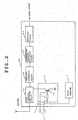
- FIG. 2 shows circuitry of an FM tuner unit 2a.
- the FM tuner unit 2a is one example of the electronic apparatus 2 shown in Figure 1.
- the FM tuner unit 2a includes a high frequency amplifying circuit 21, a frequency converting circuit 22, an intermediate frequency amplifying circuit 23, a detecting circuit 24, and a microcomputer 7.
- the FM tuner unit 2a amplifies a broadcast signal received by an antenna at the high frequency amplifying circuit 21, and then converts the signal to a signal having an intermediate frequency by the frequency converting circuit 22.
- the signal having the intermediate frequency is further amplified by the intermediate frequency amplifying circuit 23, the signal is converted to an audio signal at the detecting circuit 24, and then the signal is output as an audio output.
- the FM tuner unit 2a also includes a sensitivity switching circuit 1a which changes an amplification factor of the high frequency amplifying circuit 21 so as to switch an auto-tuning sensitivity.
- the sensitivity switching circuit 1a is one example of the common circuit 1 shown in Figure 1.
- the sensitivity switching circuit 1a is connected to the high frequency amplifying circuit 21, and serves as a switching circuit to change a bias voltage of a transistor included in the high frequency amplifying circuit 21. Specifically, the sensitivity switching circuit 1a switches the auto-tuning sensitivity by changing the amplification factor of the high frequency amplifying circuit 21 in accordance with a control signal from the microcomputer 7.
- the specific circuit function in this embodiment is a function for changing the amplification factor of the high frequency amplifying circuit 21, or a switching function for changing the bias voltage of the transistor.
- the sensitivity switching circuit 1a includes a resistor element 11 and a transistor 13 which are parts of the circuit 1a for performing the switching function.
- the resistor element 11 is a specific circuit element having two terminals, and has a resistance value Rb as a circuit constant.
- the two terminals of the resistor element 11 are connected to a pair of the measurement terminals 5 via a pair of leader lines 4.
- the leader lines 4 and the measurement terminals 5 form the current channel for measurement of the resistance value of the resistor element 11.
- the microcomputer 7 has a function of controlling an operation of the FM tuner unit 2a.
- the microcomputer 7 controls the FM tuner unit 2a differently depending on the individual specification of the unit such as the destination of the FM tuner unit 2a.
- the microcomputer 7 is provided within the FM tuner unit 2a in the present embodiment, the microcomputer may be provided outside the FM tuner unit 2a.
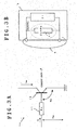
- Figures 3A and 3B illustrate an operation and a condition of the common circuit shown in Figure 1.
- the base current obtained from the above equation is a minimum required current to be supplied via the resistor element 11 having the resistance value Rb.
- a maximum value of the base current is determined by an allowable base current of the transistor 13 to be utilized.
- the allowable base current value can be several hundreds of times to several thousands of times larger than the calculated value obtained from the above equation. Because the resistance value Rb is inversely proportional to the current, on condition that the applied voltage is constant, the resistance value Rb of the resistor element 11 can be arbitrarily set within the range between the maximum value obtained from the equation, and the minimum value.
- the minimum value may be between 1/200 and 1/9000 of the maximum value.
- the resistance value Rb of the resistor element 11 can have an arbitrary value within the range, on the condition that a switching function can be achieved within the range. Accordingly, such value can represent specification information of the electronic apparatus.
- the specification information may include various information to specify the electronic apparatus such as identification information of a destination, i. e. , a country where the apparatus is exported, and identification information of a frequency band used in a wireless application, i.e., an FM tuner.
- an internal impedance Zi i.e., an impedance Zi measured via the measurement terminals 5 while the specific circuit component 11 is removed from the circuit, must be sufficiently higher, for example, several tens of times higher, than an impedance Zo.
- the impedance Zo is equal to Rb, and is determined by the circuit constant of the specific circuit component 11.
- the resistor element generally has a manufacturing error of approximately 5% which deviates from the resistance value of the nominal standard. Therefore, when the internal impedance Zi is approximately twenty times (1/0.05) or more than the resistance value of the resistor element, the resistance value can be measured within the accuracy of the manufacturing tolerance.
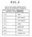
- Figure 4 is a table showing the relationship between the circuit constant and the specification information. According to the table, a series of resistance values with 1K ⁇ increment from 1K ⁇ through 7K ⁇ respectively correspond to various destinations, i.e., Japan, North America, South America, Europe, Middle East, Australia, and Southeast Asia. Accordingly, the destination of the electronic apparatus 2 which has the resistor element 11 can be identified by measuring the resistor element 11 (see Figures 1-3).
- the table is generally used to confirm the specification of the electronic apparatus based on the circuit constant, which is measured during the manufacturing process under the supervision of a manufacturer of the electronic apparatuses.
- the table may be stored in a memory of the measuring apparatus which measures the circuit constant, so that the specification information such as the identification information showing the destination can be readily displayed on the measuring apparatus in response to the measurement of the circuit constant, thereby providing a simple identification of the specification.
- FIG. 5 shows an example of the common circuit according to the present invention.
- the common circuit has a switching function on the collector current of the transistor 13 by means of the base current of the transistor 13 that is input via the resistor element 11.
- Each terminal of the resistor element 11 as the specific circuit component is connected to each of the measurement terminal pair 5 via each leader line 4.
- one terminal of the resistor element 11 is connected to an external terminal 9 which is an externally provided open terminal, and the other terminal is connected to the base of the transistor 13.
- the external terminal 9, which supplies the base current from an external source to the transistor 13, remains open during a product inspection. Therefore, a measurement current flows only to the resistor element 11 during the measurement of a resistance value R of the resistor element 11, which allows accurate measurement of the resistance value R, i.e., the circuit constant. Accordingly, the resistance value R having accurate relationship with the specification information can be obtained.
- the resistor element 11 has a function of supplying the base current which is input from the external source to the transistor 13.
- FIG. 6 shows another example of the common circuit according to the present invention.
- the common circuit outputs a change of the collector current of the transistor 13 as a voltage change generated across the terminals of the resistor element 11, which is amplified in response to the base current applied to the transistor 13.
- Both terminals of the resistor element 11 are connected to the measurement terminals 5 via leader lines 4.
- One terminal of the resistor element 11 is connected to the emitter of the transistor 13.
- the resistor element 11 has a function of transforming the change of the collector current of the transistor 13 into a change of the voltage, and has a function of outputting such change of the voltage.
- the measuring apparatus (not shown) for measuring the resistance value of the resistor element 11 is connected to the measurement terminals 5, a voltage is applied from the measuring apparatus, which may cause adverse effects on other components including the transistor 13. Damage to the transistor 13 can be prevented by applying a measuring voltage in such a manner that the emitter side has a positive potential and the base side has a negative potential, and that the measuring voltage is kept below an allowable voltage applied in the direction from the emitter to the base of the transistor 13, such as 5 volt.
- FIG. 7 shows yet another example of the common circuit according to the present invention.
- the common circuit has a function of outputting a signal to an external apparatus via the resistor element 11 and the external terminal 9. Such signal is processed by an IC 8.
- One terminal of the resistor element 11 is connected to the IC 8 provided for signal processing, and the other terminal is connected to the external apparatus via an external terminal 9 which is an externally provided open terminal.
- Both ends of the resistor element 11 are connected to measurement terminals 5 via leader lines 4. Accordingly,duringthe measurementofthecircuitconstant of the resistor element 11, the external terminal 9 remains open without contacting any external apparatus, such that the circuit constant of the resistor element 11 can be accurately measured.
- the resistor element 11 performs a function of the resistor which filters out a noise included in a signal processed in the IC, or prevents electrostatic damage of the IC.
- FIG 8 shows yet another example of the common circuit according to the present invention.
- the common circuit receives a signal via the antenna 15 and applies the signal to the tuner 14 via a capacitor 12.
- the signal is tuned, detected and amplified in the tuner 14.
- Both terminals of the capacitor 12 as the specific circuit component are connected to measurement terminals 5 via leader lines 4.
- One terminal of the capacitor 12 is connected to the antenna 15, and the other terminal is connected to the tuner 14.
- the capacitor 12 as the specific circuit component is a capacitor for cutting a DC voltage.
- the capacitor 12 has a function of preventing damage to the tuner 14 due to the voltage application from the antenna 15.
- FIG. 9 shows an embodiment of a specification identification method according to the present invention.
- the measuring apparatus is connected to the measurement terminals in order to measure the circuit constant of the specific circuit component (step S1).
- the measuring apparatus may be a conventional tester or a measuring device using a bridge balanced circuit.
- the specification information of the electronic apparatus is identified based on the measured circuit constant by using the table of the relationship between the circuit constant and the specification information (step S2).
- This step of identifying the specification information includes two steps, i.e., a comparison step in which the circuit constant is compared with a constant determined in advance based on the individual specification, and a determination step in which the specification indicated by the measured circuit constant is determined by using the comparison result of the comparison step.
- the step of identifying the specification information may be performed, for example, by storing the table showing the relationship between the circuit constant and the specification information (see Figure 4) in a memory of the measuring apparatus which measures the circuit constant, and promptly displaying the specification information, such as the destination of the measuring apparatus, upon measurement of the circuit constant.
- the specification identification method may further include an adjustment and inspection step which performs adjustment and/or inspection of the electronic apparatus in accordance with the identified specification, after performing the step of identifying the specification information.
- Figure 10 shows an embodiment of a manufacturing method according to the present invention.
- a manufacturing process of an electronic apparatus such as a tuner unit generally includes a series of steps including an automated installation step in which electronic components are automatically installed on a printed-circuit board by an automated installation machine, a soldering step in which the installed electronic components are soldered to the printed-circuit board by an automated soldering machine, an adjustment step in which the apparatus is adjusted such as an adjustment of a frequency band used in the apparatus in accordance with the specification of the tuner, an inspection step in which performance of the apparatus is inspected such as an inspection of tracking performance at the adjusted frequency band, and a shipping step in which the electronic apparatuses are prepared for shipment to a destination.
- numerical constants determined during the adjustment step or the inspection step are checked, for confirmation whether the electronic apparatuses are manufactured in accordance with the specification.
- the manufacturing method according the present invention includes a specification confirmation step in which the specification of the electronic apparatus is confirmed by using the specification identification method.
- the specification confirmation step is performed before the adjustment step and the inspection step.
- the manufacturing method includes an automated installation step (step S11), a soldering step (step S12), a specification confirmation step (step S13), an adjustment step (step S14), an inspection step (step S15) and a shipping step (step S16).
- step S13 the same method as the specification identification method is performed.
- the specification of the electronic apparatus is confirmed by the comparison step in which the measuring apparatus is connected to the measurement terminal of the electronic apparatus being manufactured, the circuit constant of the specific circuit component is measured, and the circuit constant is compared with the constant that is determined in advance based on the individual specification, and the determination step in which the specification designated by the measured circuit constant is determined by using the comparison result of the comparison step.
- the adjustment step and the inspection step are performed after the specification confirmation step. For example, when the specification information designates the identification information of the frequency band used in the electronic apparatus, the frequency of the electronic apparatus is adjusted and inspected in accordance with the confirmed frequency band.
- the manufacturing method according the present invention may not include the automated installation step (step S11), a soldering step (step S12), and a shipping step (step S16).
- the functional circuit of the electronic apparatus i.e., the circuit constant of the specific circuit component included within the common circuit, is configured to have two functions of identifying the specification and performing the specific circuit function of the common circuit.
- each specific circuit component included in the common circuit will be adjusted to have an individual circuit constant based on the individual specification.
- the common circuits included in the electronic apparatuses have the same configuration with respect to each other.
- a plurality of electronic apparatuses belonging to the same model means that the appearances, the internal structures and the functions of the electronic apparatuses are the same with respect to each other, so that the plurality of electronic apparatus are compatible with each other, when the difference of the specifications such as the frequency bands used in the apparatuses is not considered. Therefore, when the models of the electronic apparatuses are the same with respect to each other, the common circuits have the same configuration.
- the common circuits including the circuit constants of the specific circuit components have the same configuration.
- the common circuits, except for the circuit constants of the specific circuit components have the same configuration, and the circuit constants differ depending on the specification.
- the difference of the product specification can be easily identified by an electrical check at a test point provided on the electronic apparatus, i.e., the measurement terminal.
- the identification is achieved by differentiating the circuit constant which is adjustable within a predetermined range in accordance with the specification such as the destination.
- the circuits are provided in all electronic apparatuses belonging to the same model.
- the embodiment and examples have been described based on the resistor element as the specific circuit component which is adjusted to have a different resistant value depending on the difference of the specification such as the destination, but the specific circuit component is not limited to the resistor.
- the specific circuit component maybe any electronic components having two terminals such as a capacitor and a coil, which have a measurable circuit constant such as a capacity value and an inductance value, respectively.
- the electronic apparatus may include a plurality of electronic components having different values corresponding to different specification information. By combining the circuit constants among a plurality of circuit components, various information can be expressed. In this instance, a plurality of measurement terminals and a plurality of current channels are necessary depending on the number of circuit components.
- the electronic apparatus according to the present invention is not limited to the tuner unit, and can be applied to various electronic apparatuses.
Landscapes
- Engineering & Computer Science (AREA)
- Computer Hardware Design (AREA)
- Microelectronics & Electronic Packaging (AREA)
- Monitoring And Testing Of Transmission In General (AREA)
- Circuits Of Receivers In General (AREA)
- Tests Of Electronic Circuits (AREA)
- Input Circuits Of Receivers And Coupling Of Receivers And Audio Equipment (AREA)
Abstract
Description
Claims (15)
- An electronic apparatus comprising:wherein the circuit constant has a value in accordance with a specification.a specific circuit component having a circuit constant included in a function circuit providing a specific circuit function; anda measurement terminal for measuring the circuit constant;
- The electronic apparatus according to claim 1, wherein the circuit constant of the specific circuit component has a value suitable for identifying the specification and performing the specific circuit function by the function circuit.
- The electronic apparatus according to claim 1, wherein an internal impedance measured via the measurement terminal while the specific circuit component is removed is higher than an impedance of the specific circuit component.
- The electronic apparatus according to claim 1, wherein the specific circuit component forms a part of a circuit which switches an auto-tuning sensitivity within the function circuit.
- The electronic apparatus according to claim 4 , wherein the circuit which switches the auto-tuning sensitivity is a switching circuit which switches the auto-tuning sensitivity by changing an amplification factor of a high frequency amplifier in response to a control signal from a microcomputer.
- The electronic apparatus according to claim 1, wherein the specific circuit component is a resistor having two terminals, a capacitor having two terminals, or a coil having two terminals.
- The electronic apparatus according to claim 6 , wherein one terminal of the specific circuit component is connected to an external terminal.
- The electronic apparatus according to claim 7 , wherein another terminal of the specific circuit component is connected to an internal IC for filtering noise or preventing electrostatic damage.
- The electronic apparatus according to claim 6 , wherein the specific circuit component is connected between the external antenna and the tuner for prevention of damage to the tuner.
- The electronic apparatus according to claim 1, wherein the specification is identification information of a destination of the electronic apparatus.
- The electronic apparatus according to claim 1, wherein the specification is identification information of a frequency band used in the electronic apparatus.
- A specification identification method for an electronic apparatus including a specific circuit component having a circuit constant included in a function circuit having a specific circuit function, and a measurement terminal for measuring the circuit constant, the method comprising:measuring the circuit constant by connecting the measurement terminal with a measuring apparatus; andidentifying a specification in accordance with a value of the measured circuit constant.
- The specification identification method according to claim 12, wherein the identification step includes comparing the circuit constant with a constant that is predetermined based on the individual specification, and determining the specification by using the comparison result.
- A manufacturing method for an electronic apparatus including a specific circuit component having a circuit constant included in a function circuit having a specific circuit function, and a measurement terminal for measuring the circuit constant, the method comprising:providing the specific circuit component and the measurement terminal;measuring the circuit constant by connecting the measurement terminal with a measuring apparatus; andidentifying a specification in accordance with a value of the measured circuit constant.
- The manufacturing method according to claim 14 further including adjusting and/or inspecting the electronic apparatus in accordance with the identified specification.
Applications Claiming Priority (2)
| Application Number | Priority Date | Filing Date | Title |
|---|---|---|---|
| JP2002295231 | 2002-10-08 | ||
| JP2002295231A JP2004134882A (en) | 2002-10-08 | 2002-10-08 | Electronic device, method of identifying specification thereof, and manufacturing method |
Publications (2)
| Publication Number | Publication Date |
|---|---|
| EP1408609A2 true EP1408609A2 (en) | 2004-04-14 |
| EP1408609A3 EP1408609A3 (en) | 2004-12-08 |
Family
ID=32025516
Family Applications (1)
| Application Number | Title | Priority Date | Filing Date |
|---|---|---|---|
| EP03256099A Withdrawn EP1408609A3 (en) | 2002-10-08 | 2003-09-29 | Electronic apparatus and method for identifying its specifications |
Country Status (3)
| Country | Link |
|---|---|
| US (1) | US6946862B2 (en) |
| EP (1) | EP1408609A3 (en) |
| JP (1) | JP2004134882A (en) |
Families Citing this family (5)
| Publication number | Priority date | Publication date | Assignee | Title |
|---|---|---|---|---|
| JP3901698B2 (en) * | 2004-03-26 | 2007-04-04 | ローム株式会社 | Semiconductor integrated circuit with current detection function and power supply device using the same |
| EP1926138A4 (en) * | 2005-08-18 | 2011-06-22 | Advantest Corp | DEVICE IDENTIFICATION METHOD, DEVICE MANUFACTURING METHOD, AND ELECTRONIC DEVICE |
| US8966660B2 (en) * | 2008-08-07 | 2015-02-24 | William Marsh Rice University | Methods and systems of digital rights management for integrated circuits |
| US8740444B2 (en) | 2011-12-21 | 2014-06-03 | Lumenpulse Lighting, Inc. | Light source circuit boards |
| US11172380B2 (en) * | 2019-01-24 | 2021-11-09 | Apple Inc. | Systems and methods for real-time adaptive antenna frequency response optimization for multi-carrier wireless systems |
Family Cites Families (7)
| Publication number | Priority date | Publication date | Assignee | Title |
|---|---|---|---|---|
| GB2251105A (en) * | 1990-12-11 | 1992-06-24 | Race Electronics Limited | An identification component |
| US5497094A (en) * | 1994-01-21 | 1996-03-05 | George; David L. | Electrical circuit identification means |
| DE19624858A1 (en) * | 1996-06-21 | 1998-01-02 | Nokia Mobile Phones Ltd | ASIC application specified integrated circuit with self-test function |
| US6087841A (en) * | 1997-10-01 | 2000-07-11 | International Business Machines Corporation | Contact test circuit |
| US6161213A (en) * | 1999-02-17 | 2000-12-12 | Icid, Llc | System for providing an integrated circuit with a unique identification |
| JP2001156591A (en) * | 1999-11-25 | 2001-06-08 | Alps Electric Co Ltd | Active filter and its band adjustment method |
| US7143500B2 (en) * | 2001-06-25 | 2006-12-05 | Micron Technology, Inc. | Method to prevent damage to probe card |
-
2002
- 2002-10-08 JP JP2002295231A patent/JP2004134882A/en not_active Abandoned
-
2003
- 2003-09-29 EP EP03256099A patent/EP1408609A3/en not_active Withdrawn
- 2003-10-03 US US10/677,343 patent/US6946862B2/en not_active Expired - Fee Related
Also Published As
| Publication number | Publication date |
|---|---|
| US20040085056A1 (en) | 2004-05-06 |
| US6946862B2 (en) | 2005-09-20 |
| EP1408609A3 (en) | 2004-12-08 |
| JP2004134882A (en) | 2004-04-30 |
Similar Documents
| Publication | Publication Date | Title |
|---|---|---|
| US6374084B1 (en) | Method and system for calibrating electronic devices using polynomial fit calibration scheme | |
| JP5735856B2 (en) | Semiconductor chip and semiconductor chip inspection method | |
| JP4828542B2 (en) | Impedance detector | |
| KR100329402B1 (en) | Signal conditioning devices and methods for accurate input impedance and gain characteristics across the common mode range and operating environment | |
| US10955497B2 (en) | Phase compensation circuit, magnetic induction imaging device and phase compensation method | |
| US20060005065A1 (en) | Network analyzer, network analyzing method, automatic corrector, correcting method, program, and recording medium | |
| KR20110009150A (en) | Microphone assembly with integrated self-test circuitry | |
| JPH1054851A (en) | Instrument for measuring output current of power source | |
| CN112731241B (en) | Calibration tool and calibration method for wafer test machine | |
| US6946862B2 (en) | Electronic apparatus, specification identification method therefor and manufacturing method therefor | |
| US7129719B2 (en) | Apparatus for detecting defect in circuit pattern and defect detecting system having the same | |
| CN115060982B (en) | Active near-field composite probe, detection device and probe calibration method | |
| EP1209474A1 (en) | System and method for measuring the power consumed by a circuit on a printed circuit board | |
| US4733173A (en) | Electronic component measurement apparatus | |
| US3731186A (en) | Radio frequency measurements | |
| US20050163326A1 (en) | Diagnostic circuit for a tweeter ina loudspeaker combination | |
| KR890004530Y1 (en) | Circuit of electric current gain of transistor | |
| KR100476740B1 (en) | Method for testing rlc parallel circuit on the printed circuit board | |
| JPS633464B2 (en) | ||
| US8593198B2 (en) | Signal generator and signal strength detecting circuit having the signal generator installed therein | |
| KR102334597B1 (en) | Impedance monitoring apparatus and operating method thereof | |
| CN103813256B (en) | For examining the circuit device and method and the system of driving microphone of microphone | |
| CN111123772B (en) | Auxiliary control circuit of power amplifier module, power amplifier module and communication equipment | |
| KR0167460B1 (en) | Contact signal and signal separation check circuit of the product itself during product inspection | |
| KR200304761Y1 (en) | An adapter for measuring RF cable loss coeficient of mobile communication terminal test equipment |
Legal Events
| Date | Code | Title | Description |
|---|---|---|---|
| PUAI | Public reference made under article 153(3) epc to a published international application that has entered the european phase |
Free format text: ORIGINAL CODE: 0009012 |
|
| AK | Designated contracting states |
Kind code of ref document: A2 Designated state(s): AT BE BG CH CY CZ DE DK EE ES FI FR GB GR HU IE IT LI LU MC NL PT RO SE SI SK TR |
|
| AX | Request for extension of the european patent |
Extension state: AL LT LV MK |
|
| PUAL | Search report despatched |
Free format text: ORIGINAL CODE: 0009013 |
|
| AK | Designated contracting states |
Kind code of ref document: A3 Designated state(s): AT BE BG CH CY CZ DE DK EE ES FI FR GB GR HU IE IT LI LU MC NL PT RO SE SI SK TR |
|
| AX | Request for extension of the european patent |
Extension state: AL LT LV MK |
|
| RIC1 | Information provided on ipc code assigned before grant |
Ipc: 7H 03J 1/00 B Ipc: 7H 05K 1/02 A |
|
| 17P | Request for examination filed |
Effective date: 20050114 |
|
| AKX | Designation fees paid |
Designated state(s): DE FR GB IT |
|
| 17Q | First examination report despatched |
Effective date: 20050803 |
|
| GRAP | Despatch of communication of intention to grant a patent |
Free format text: ORIGINAL CODE: EPIDOSNIGR1 |
|
| STAA | Information on the status of an ep patent application or granted ep patent |
Free format text: STATUS: THE APPLICATION HAS BEEN WITHDRAWN |
|
| 18W | Application withdrawn |
Effective date: 20071031 |