EP1408518B1 - Sintered R-Fe-B permanent magnet and its production method - Google Patents
Sintered R-Fe-B permanent magnet and its production method Download PDFInfo
- Publication number
- EP1408518B1 EP1408518B1 EP03022684A EP03022684A EP1408518B1 EP 1408518 B1 EP1408518 B1 EP 1408518B1 EP 03022684 A EP03022684 A EP 03022684A EP 03022684 A EP03022684 A EP 03022684A EP 1408518 B1 EP1408518 B1 EP 1408518B1
- Authority
- EP
- European Patent Office
- Prior art keywords
- mass
- magnet
- slurry
- sintered body
- green body
- Prior art date
- Legal status (The legal status is an assumption and is not a legal conclusion. Google has not performed a legal analysis and makes no representation as to the accuracy of the status listed.)
- Expired - Lifetime
Links
- 238000004519 manufacturing process Methods 0.000 title claims abstract description 16
- 239000000843 powder Substances 0.000 claims abstract description 119
- 239000002002 slurry Substances 0.000 claims abstract description 92
- 239000002480 mineral oil Substances 0.000 claims abstract description 61
- 235000010446 mineral oil Nutrition 0.000 claims abstract description 61
- 239000003921 oil Substances 0.000 claims abstract description 40
- KWSLGOVYXMQPPX-UHFFFAOYSA-N 5-[3-(trifluoromethyl)phenyl]-2h-tetrazole Chemical compound FC(F)(F)C1=CC=CC(C2=NNN=N2)=C1 KWSLGOVYXMQPPX-UHFFFAOYSA-N 0.000 claims abstract description 37
- 229910001379 sodium hypophosphite Inorganic materials 0.000 claims abstract description 37
- PEDCQBHIVMGVHV-UHFFFAOYSA-N Glycerine Chemical compound OCC(O)CO PEDCQBHIVMGVHV-UHFFFAOYSA-N 0.000 claims abstract description 34
- 229910052761 rare earth metal Inorganic materials 0.000 claims abstract description 33
- LFQSCWFLJHTTHZ-UHFFFAOYSA-N Ethanol Chemical compound CCO LFQSCWFLJHTTHZ-UHFFFAOYSA-N 0.000 claims abstract description 30
- 238000005245 sintering Methods 0.000 claims abstract description 24
- 235000011187 glycerol Nutrition 0.000 claims abstract description 17
- 238000010298 pulverizing process Methods 0.000 claims abstract description 13
- 150000002910 rare earth metals Chemical class 0.000 claims abstract description 8
- 239000003795 chemical substances by application Substances 0.000 claims abstract description 6
- 238000010438 heat treatment Methods 0.000 claims abstract description 6
- 239000000463 material Substances 0.000 claims abstract description 3
- 239000000203 mixture Substances 0.000 claims description 84
- 230000004907 flux Effects 0.000 claims description 69
- 238000000034 method Methods 0.000 claims description 24
- 238000009826 distribution Methods 0.000 claims description 7
- XEEYBQQBJWHFJM-UHFFFAOYSA-N Iron Chemical compound [Fe] XEEYBQQBJWHFJM-UHFFFAOYSA-N 0.000 abstract description 41
- 229910052760 oxygen Inorganic materials 0.000 abstract description 31
- 239000001301 oxygen Substances 0.000 abstract description 30
- QVGXLLKOCUKJST-UHFFFAOYSA-N atomic oxygen Chemical compound [O] QVGXLLKOCUKJST-UHFFFAOYSA-N 0.000 abstract description 29
- IJGRMHOSHXDMSA-UHFFFAOYSA-N Atomic nitrogen Chemical compound N#N IJGRMHOSHXDMSA-UHFFFAOYSA-N 0.000 abstract description 26
- 229910052757 nitrogen Inorganic materials 0.000 abstract description 6
- 229910052742 iron Inorganic materials 0.000 abstract description 4
- OKTJSMMVPCPJKN-UHFFFAOYSA-N Carbon Chemical compound [C] OKTJSMMVPCPJKN-UHFFFAOYSA-N 0.000 abstract description 3
- OAICVXFJPJFONN-UHFFFAOYSA-N Phosphorus Chemical compound [P] OAICVXFJPJFONN-UHFFFAOYSA-N 0.000 abstract description 2
- 229910052799 carbon Inorganic materials 0.000 abstract description 2
- 229910052698 phosphorus Inorganic materials 0.000 abstract description 2
- 239000011574 phosphorus Substances 0.000 abstract description 2
- ZOXJGFHDIHLPTG-UHFFFAOYSA-N Boron Chemical compound [B] ZOXJGFHDIHLPTG-UHFFFAOYSA-N 0.000 abstract 1
- 229910052796 boron Inorganic materials 0.000 abstract 1
- 229910052727 yttrium Inorganic materials 0.000 abstract 1
- VWQVUPCCIRVNHF-UHFFFAOYSA-N yttrium atom Chemical compound [Y] VWQVUPCCIRVNHF-UHFFFAOYSA-N 0.000 abstract 1
- 230000000052 comparative effect Effects 0.000 description 59
- 235000019198 oils Nutrition 0.000 description 34
- 238000012360 testing method Methods 0.000 description 33
- 238000000465 moulding Methods 0.000 description 32
- 238000004458 analytical method Methods 0.000 description 27
- 239000010949 copper Substances 0.000 description 27
- 239000012298 atmosphere Substances 0.000 description 23
- 239000000047 product Substances 0.000 description 22
- 238000002347 injection Methods 0.000 description 18
- 239000007924 injection Substances 0.000 description 18
- 239000000243 solution Substances 0.000 description 18
- 229910001873 dinitrogen Inorganic materials 0.000 description 16
- 239000010955 niobium Substances 0.000 description 15
- 230000007423 decrease Effects 0.000 description 14
- 239000007789 gas Substances 0.000 description 14
- 230000000694 effects Effects 0.000 description 13
- 239000012071 phase Substances 0.000 description 13
- 238000004453 electron probe microanalysis Methods 0.000 description 12
- 238000011049 filling Methods 0.000 description 12
- 238000003754 machining Methods 0.000 description 12
- 230000005415 magnetization Effects 0.000 description 10
- 229910045601 alloy Inorganic materials 0.000 description 8
- 239000000956 alloy Substances 0.000 description 8
- 238000005259 measurement Methods 0.000 description 8
- 238000007254 oxidation reaction Methods 0.000 description 8
- 238000005336 cracking Methods 0.000 description 7
- 230000007797 corrosion Effects 0.000 description 6
- 238000005260 corrosion Methods 0.000 description 6
- 239000013078 crystal Substances 0.000 description 6
- 230000003647 oxidation Effects 0.000 description 6
- 239000002904 solvent Substances 0.000 description 6
- 230000015572 biosynthetic process Effects 0.000 description 5
- 238000002156 mixing Methods 0.000 description 5
- 230000003247 decreasing effect Effects 0.000 description 4
- 150000004767 nitrides Chemical class 0.000 description 4
- 238000005121 nitriding Methods 0.000 description 4
- 239000002245 particle Substances 0.000 description 4
- 239000007864 aqueous solution Substances 0.000 description 3
- 238000005520 cutting process Methods 0.000 description 3
- 238000000280 densification Methods 0.000 description 3
- 238000002844 melting Methods 0.000 description 3
- 239000000523 sample Substances 0.000 description 3
- 229910001096 P alloy Inorganic materials 0.000 description 2
- 230000002159 abnormal effect Effects 0.000 description 2
- 229910052782 aluminium Inorganic materials 0.000 description 2
- 230000006866 deterioration Effects 0.000 description 2
- 229910052733 gallium Inorganic materials 0.000 description 2
- 239000011261 inert gas Substances 0.000 description 2
- 239000007791 liquid phase Substances 0.000 description 2
- 230000005381 magnetic domain Effects 0.000 description 2
- 230000008018 melting Effects 0.000 description 2
- 229910052758 niobium Inorganic materials 0.000 description 2
- 239000010453 quartz Substances 0.000 description 2
- VYPSYNLAJGMNEJ-UHFFFAOYSA-N silicon dioxide Inorganic materials O=[Si]=O VYPSYNLAJGMNEJ-UHFFFAOYSA-N 0.000 description 2
- 239000007858 starting material Substances 0.000 description 2
- 235000015112 vegetable and seed oil Nutrition 0.000 description 2
- 239000008158 vegetable oil Substances 0.000 description 2
- 239000011800 void material Substances 0.000 description 2
- 229910052692 Dysprosium Inorganic materials 0.000 description 1
- 229910000640 Fe alloy Inorganic materials 0.000 description 1
- GYHNNYVSQQEPJS-UHFFFAOYSA-N Gallium Chemical compound [Ga] GYHNNYVSQQEPJS-UHFFFAOYSA-N 0.000 description 1
- 229910019386 NaPH2O2 Inorganic materials 0.000 description 1
- 230000002378 acidificating effect Effects 0.000 description 1
- 230000001154 acute effect Effects 0.000 description 1
- XAGFODPZIPBFFR-UHFFFAOYSA-N aluminium Chemical compound [Al] XAGFODPZIPBFFR-UHFFFAOYSA-N 0.000 description 1
- 239000003945 anionic surfactant Substances 0.000 description 1
- 239000003125 aqueous solvent Substances 0.000 description 1
- 229910052797 bismuth Inorganic materials 0.000 description 1
- JCXGWMGPZLAOME-UHFFFAOYSA-N bismuth atom Chemical compound [Bi] JCXGWMGPZLAOME-UHFFFAOYSA-N 0.000 description 1
- 239000005388 borosilicate glass Substances 0.000 description 1
- 238000004364 calculation method Methods 0.000 description 1
- 230000008859 change Effects 0.000 description 1
- 238000006243 chemical reaction Methods 0.000 description 1
- 239000010941 cobalt Substances 0.000 description 1
- 229910017052 cobalt Inorganic materials 0.000 description 1
- GUTLYIVDDKVIGB-UHFFFAOYSA-N cobalt atom Chemical compound [Co] GUTLYIVDDKVIGB-UHFFFAOYSA-N 0.000 description 1
- 229910052802 copper Inorganic materials 0.000 description 1
- 238000001035 drying Methods 0.000 description 1
- 238000011156 evaluation Methods 0.000 description 1
- 239000010439 graphite Substances 0.000 description 1
- 229910002804 graphite Inorganic materials 0.000 description 1
- 238000007731 hot pressing Methods 0.000 description 1
- 230000006872 improvement Effects 0.000 description 1
- 230000003993 interaction Effects 0.000 description 1
- 239000007788 liquid Substances 0.000 description 1
- 229910052751 metal Inorganic materials 0.000 description 1
- 239000002184 metal Substances 0.000 description 1
- 150000001247 metal acetylides Chemical class 0.000 description 1
- 150000002739 metals Chemical class 0.000 description 1
- GUCVJGMIXFAOAE-UHFFFAOYSA-N niobium atom Chemical compound [Nb] GUCVJGMIXFAOAE-UHFFFAOYSA-N 0.000 description 1
- QJGQUHMNIGDVPM-UHFFFAOYSA-N nitrogen group Chemical group [N] QJGQUHMNIGDVPM-UHFFFAOYSA-N 0.000 description 1
- 239000002736 nonionic surfactant Substances 0.000 description 1
- 230000002093 peripheral effect Effects 0.000 description 1
- 230000008569 process Effects 0.000 description 1
- 238000011160 research Methods 0.000 description 1
- 229920006395 saturated elastomer Polymers 0.000 description 1
- 239000007787 solid Substances 0.000 description 1
- 230000002269 spontaneous effect Effects 0.000 description 1
- 239000013589 supplement Substances 0.000 description 1
- 238000009827 uniform distribution Methods 0.000 description 1
- XLYOFNOQVPJJNP-UHFFFAOYSA-N water Substances O XLYOFNOQVPJJNP-UHFFFAOYSA-N 0.000 description 1
- 238000004876 x-ray fluorescence Methods 0.000 description 1
Images


Classifications
-
- C—CHEMISTRY; METALLURGY
- C22—METALLURGY; FERROUS OR NON-FERROUS ALLOYS; TREATMENT OF ALLOYS OR NON-FERROUS METALS
- C22C—ALLOYS
- C22C38/00—Ferrous alloys, e.g. steel alloys
- C22C38/005—Ferrous alloys, e.g. steel alloys containing rare earths, i.e. Sc, Y, Lanthanides
-
- H—ELECTRICITY
- H01—ELECTRIC ELEMENTS
- H01F—MAGNETS; INDUCTANCES; TRANSFORMERS; SELECTION OF MATERIALS FOR THEIR MAGNETIC PROPERTIES
- H01F1/00—Magnets or magnetic bodies characterised by the magnetic materials therefor; Selection of materials for their magnetic properties
- H01F1/01—Magnets or magnetic bodies characterised by the magnetic materials therefor; Selection of materials for their magnetic properties of inorganic materials
- H01F1/03—Magnets or magnetic bodies characterised by the magnetic materials therefor; Selection of materials for their magnetic properties of inorganic materials characterised by their coercivity
- H01F1/032—Magnets or magnetic bodies characterised by the magnetic materials therefor; Selection of materials for their magnetic properties of inorganic materials characterised by their coercivity of hard-magnetic materials
- H01F1/04—Magnets or magnetic bodies characterised by the magnetic materials therefor; Selection of materials for their magnetic properties of inorganic materials characterised by their coercivity of hard-magnetic materials metals or alloys
- H01F1/047—Alloys characterised by their composition
- H01F1/053—Alloys characterised by their composition containing rare earth metals
- H01F1/055—Alloys characterised by their composition containing rare earth metals and magnetic transition metals, e.g. SmCo5
- H01F1/057—Alloys characterised by their composition containing rare earth metals and magnetic transition metals, e.g. SmCo5 and IIIa elements, e.g. Nd2Fe14B
- H01F1/0571—Alloys characterised by their composition containing rare earth metals and magnetic transition metals, e.g. SmCo5 and IIIa elements, e.g. Nd2Fe14B in the form of particles, e.g. rapid quenched powders or ribbon flakes
- H01F1/0575—Alloys characterised by their composition containing rare earth metals and magnetic transition metals, e.g. SmCo5 and IIIa elements, e.g. Nd2Fe14B in the form of particles, e.g. rapid quenched powders or ribbon flakes pressed, sintered or bonded together
- H01F1/0577—Alloys characterised by their composition containing rare earth metals and magnetic transition metals, e.g. SmCo5 and IIIa elements, e.g. Nd2Fe14B in the form of particles, e.g. rapid quenched powders or ribbon flakes pressed, sintered or bonded together sintered
-
- H—ELECTRICITY
- H01—ELECTRIC ELEMENTS
- H01F—MAGNETS; INDUCTANCES; TRANSFORMERS; SELECTION OF MATERIALS FOR THEIR MAGNETIC PROPERTIES
- H01F41/00—Apparatus or processes specially adapted for manufacturing or assembling magnets, inductances or transformers; Apparatus or processes specially adapted for manufacturing materials characterised by their magnetic properties
- H01F41/02—Apparatus or processes specially adapted for manufacturing or assembling magnets, inductances or transformers; Apparatus or processes specially adapted for manufacturing materials characterised by their magnetic properties for manufacturing cores, coils, or magnets
- H01F41/0253—Apparatus or processes specially adapted for manufacturing or assembling magnets, inductances or transformers; Apparatus or processes specially adapted for manufacturing materials characterised by their magnetic properties for manufacturing cores, coils, or magnets for manufacturing permanent magnets
- H01F41/0273—Imparting anisotropy
Definitions
- the present invention relates to a sintered R-Fe-B permanent magnet having an improved coercivity iHc due to a desired amount of P and its production method, particularly to a high-performance, radially anisotropic sintered R-Fe-B permanent magnet excellent in the uniformity of a surface magnetic flux density, and its efficient production method.
- R-Fe-B permanent magnets have been produced for many years by so-called dry molding methods, in which dry fine powder is molded in a die while applying a magnetic field.
- the concentration of oxygen in a nitrogen or Ar gas, a pulverization medium is usually controlled in a desired range by introducing a trace amount of oxygen into a jet mill in the fine pulverization of a coarse starting material powder in the jet mill. This is to cause the oxidization of fine powder surfaces. Finely pulverized powder would be burned without this oxidation treatment, when brought into contact with the air.
- the fine powder subjected to the oxidation treatment has an oxygen content of 5000-6000 ppm, and the sintered body obtained from this fine powder has an oxygen content of 4000-5000 ppm.
- Most of oxygen in the sintered body is bonded to rare earth elements such as Nd, etc., existing as oxides in the grain boundaries.
- the total amount of rare earth elements in the sintered body should be increased, resulting in decrease in the saturation magnetic flux density of the sintered magnet.
- JP 7-57914 A proposes a method for producing a sintering rare earth magnet comprising the steps of injecting a mixture of rare earth magnet powder and a mineral oil or a synthetic oil under pressure into a die cavity, to which an oriented magnetic field is applied, wet-molding it in a magnetic field in a low-oxygen atmosphere to form a ring-shaped green body, removing the solvent from the green body, and sintering the green body in vacuum.
- This method can stably produce high-performance, sintered R-Fe-B permanent magnets having a small total amount of rare earth elements and a small oxygen content.
- the fine R-Fe-B powder having large spontaneous magnetization oriented is subjected to large constraint by interaction with the oriented magnetic field, resulting in a nonuniform filling density in the die cavity.
- the resultant green body has a nonuniform density, causing deformation and cracking in the resultant sintered body.
- the slurry is injected into the die cavity under pressure toward a core center through an injection aperture open in the die cavity, the slurry impinging the core is divided to flows in two directions, which are converged on the opposite side of the injection aperture by 180°, so that the resultant sintered body has cracks generated from this converging position.
- JP 11-214216 A proposes a method for producing a sintered R-Fe-B permanent magnet comprising the steps of ejecting a slurry of a powder of an R-Fe-B permanent magnet, and a solvent such as a mineral oil, a synthetic oil or a vegetable oil through a slurry-supplying pipe inserted into a die cavity, to which a magnetic field is applied, molding the slurry filled in the cavity under pressure while gradually withdrawing the slurry-supplying pipe from the cavity, removing the solvent from the resultant ring-shaped green body, and sintering the green body.
- a solvent such as a mineral oil, a synthetic oil or a vegetable oil
- the die cavity is filled with the slurry at a good filling ratio even in the case of molding a relatively long ring-shaped green body.
- the slurry-supplying pipe is inserted deep into the die cavity and withdrawn while ejecting the slurry, this method is disadvantageous in a long supplying time of the slurry.
- the slurry-supplying pipe leaves a void in the resultant green body at a position thereof, and this void acts as a starting position of cracking in the resultant sintered R-Fe-B permanent magnet.
- Proposed as another method for producing a radially anisotropic ring-shaped R-Fe-B permanent magnet is a method comprising the steps of pulverizing quenched ribbons of an R-Fe-B magnet alloy, molding the resultant powder at room temperature, hot-pressing the resultant green body in an inert gas atmosphere for densification, hot-plastic-working the resultant hot-pressed body to form a cup body provided with radial magnetic anisotropy, and cutting a bottom portion off to provide a ring-shaped product ( JP 9-275004 A , JP 2001-181802 A ).
- the hot plastic working of the hot-pressed body in an inert gas atmosphere is carried out at a relatively low temperature of about 700-800°C so that crystal grains do not grow too much, it should be conducted at an extremely low speed to prevent cracking.
- one hot plastic working operation usually takes 10-30 minutes, low productivity as an industrial method for producing permanent magnets.
- pressed bodies thus produced are likely to have cracks in their end portions, cracked portions should be cut off. For these reasons, this production method suffers from a high production cost.
- the resultant ring magnet has large variations of magnetic properties. Though the degree of radial anisotropy depends on how much deformed in the hot plastic working, particularly small-diameter products and long products having large hot plastic working resistance suffer from large variations of a surface magnetic flux density.
- DE 100 32 515 A1 provides a thin arc segment magnet made of a rare earth sintered magnet substantially comprising 28-33 weight % of R and 0.8-1.5 weight % of B, the balance being substantially Fe, wherein R is at least one rare earth element including Y, and T is Fe or Fe and Co, which has an oxygen content of 0.3 weight % or less, a density of 7.56 g/cm 3 or more, a coercivity iHc of 1.1 MA/m (14 kOe) or more at room temperature, and an orientation Br/4 ⁇ I max of 96% or more in an anisotropy-providing direction at room temperature.
- the magnet is produced by using a slurry mixture formed by introducing fine alloy powder of the above composition into a mixture liquid comprising 99.7-99.99 parts by weight of a mineral oil, a synthetic oil or a vegetable oil and 0.01-0.3 parts by weight of a non-ionic surfactant and/or an anionic surfactant.
- the magnet of this document does not include P and is produced by a slurry which is injected towards the center core of the magnet forming mold and includes no sodium hypophosphite as a fluidity-improving agent.
- an object of the present invention is to provide a sintered R-Fe-B permanent magnet having an improved coercivity iHc due to a desired amount of P, particularly a radially anisotropic sintered R-Fe-B permanent magnet free from deformation and cracking and having excellent magnetic orientation, and a production method thereof.
- Another object of the present invention is to provide a method for producing a radially anisotropic sintered R-Fe-B permanent magnet having high magnetic properties with little variation of a surface magnetic flux density at a high productivity.
- the sintered permanent magnet according to an embodiment of the present invention has a composition comprising, by mass, 27-33.5% of R, which is at least one of rare earth elements including Y, 0.5-2% of B, 0.002-0.15% of N, 0.25% or less of O, 0.15% or less of C, and 0.001-0.05% of P, the balance being Fe, wherein it has a coercivity iHc of 1 MA/m or more.
- R which is at least one of rare earth elements including Y, 0.5-2% of B, 0.002-0.15% of N, 0.25% or less of O, 0.15% or less of C, and 0.001-0.05% of P, the balance being Fe, wherein it has a coercivity iHc of 1 MA/m or more.
- the term "sintered permanent magnet” used herein includes both of sintered bodies made of permanent magnet materials before magnetization and those after magnetization. The coercivity is measured at room temperature (25°C).
- the sintered permanent magnet of the present invention may be a small ring magnet having an outer diameter of 10-30 mm, an inner diameter 8-28 mm and a height of 10-50 mm, particularly an outer diameter of 10-25 mm, an inner diameter 8-23 mm and a height of 10-40 mm.
- the sintered permanent magnet of the present invention is preferably a radially anisotropic sintered R-Fe-B permanent magnet.
- the sintered permanent magnet of the present invention preferably has a density of 7.52-7.85 g/cm 3 .
- a distribution of a surface magnetic flux density B 0 along the axial magnetic pole in the above ring magnet is preferably in a range of 92.5% or more of the maximum of B 0 .
- the variation of a surface magnetic flux density B 0 in the axial direction of the ring magnet is preferably 7.5% or less of the maximum of B 0 .
- the variation of a surface magnetic flux density B 0 is represented by the formula of [(maximum of B 0 - minimum of B 0 ) / maximum of B 0 ] x 100 (%).
- the maximum and minimum of B 0 are measured in a range of a height H of the ring magnet.
- the distribution of a surface magnetic flux density B 0 is measured by placing a probe of a Gauss meter opposite to an outer circumferential surface of the ring magnet perpendicularly, and moving it on the outer circumferential surface in the axial direction of the ring magnet (length direction).
- the variation of a surface magnetic flux density B 0 is more preferably within 5%, particularly within 3%.
- R is 27-32% by mass. In an illustrative example useful to understand the present invention, R is more than 32% and 33.5% or less by mass.
- the sintered permanent magnet has a composition comprising, by mass, more than 32% and 33.5% or less of R, which is at least one of rare earth elements including Y, 0.5-2% of B, more than 0.25% and 0.6% or less of O, 0.01-0.15% of C, 0.002-0.05% of N, and 0.001-0.05% of P, the balance being Fe, wherein it is in the shape of a ring having an outer diameter of 10-100 mm, an inner diameter of 8-96 mm, and a height of 10-70 mm, wherein it has magnetic anisotropy in a radical direction of the ring, and wherein a distribution of a surface magnetic flux density B 0 on magnetic pole in the axial direction of the ring is in a range of 92.5% or more of the maximum of B 0 .
- Sodium hypophosphite is added preferably in the form of a solution in glycerin or ethanol, though it is possible to dissolve sodium hypophosphite in a non-aqueous solvent instead of forming a solution in glycerin or ethanol. However, from the aspect of easiness in handling a solvent, glycerin or ethanol is desirable as a solvent.
- the sintered permanent magnet of the present invention generally has a composition comprising, by mass, 27-33.5% of R, which is at least one of rare earth elements including Y, 0.5-2% of B, 0.002-0.15% of N, 0.25% or less of O, 0.15% or less of C, and 0.001-0.05% of P, the balance being Fe.
- R which is at least one of rare earth elements including Y, 0.5-2% of B, 0.002-0.15% of N, 0.25% or less of O, 0.15% or less of C, and 0.001-0.05% of P, the balance being Fe.
- the content of each element can be measured by an X-ray fluorescence analysis, etc.
- the content of the rare earth element R is generally 27-33.5% by mass.
- the content of the rare earth element exceeding 33.5% by mass results in decrease in a saturation magnetic flux density and the deterioration of a corrosion resistance.
- the content of the rare earth element is less than 27% by mass, the amount of a liquid phase necessary for the densification of the sintered body is insufficient, resulting in providing the sintered body with low density and coercivity iHc.
- R is 27-32% by mass in the first preferred composition of the present invention, and R is more than 32% and 33.5% or less by mass in the second preferred composition.
- the amount of the rare earth element R is preferably more than 32% and 33.5% or less by mass.
- the amount of the rare earth element exceeds 33.5% by mass, the amount of a rare earth-rich phase in the sintered body increases, accompanied by increase in its size, thus resulting in the deterioration of a corrosion resistance.
- the amount of the rare earth element is 32% or less by mass, the amount of a liquid phase necessary for the densification of the sintered body is insufficient, thereby providing the sintered body with decreased density, as well as a decreased residual magnetic flux density Br and decreased coercivity iHc among magnetic properties.
- R is preferably limited to 32% or less by mass.
- the content of B is generally 0.5-2% by mass.
- B necessary for the formation of an R 2 Fe 14 B phase, a main phase is insufficient, and an R 2 Fe 17 phase having soft magnetic properties is formed, resulting in decrease in coercivity iHc.
- a B-rich phase, non-magnetic phase increases, resulting in decrease in a residual magnetic flux density Br.
- the content of N is generally 0.002-0.15% by mass.
- N exists mainly in an R-rich phase in the sintered body, bonding to part of the rare earth element to form nitrides. It is presumed that the formation of nitrides suppresses the anodic oxidation of a grain boundary phase, improving the corrosion resistance of the sintered body.
- the content of N exceeds 0.15% by mass, the formation of nitrides decreases the amount of rare earth elements necessary for having the coercivity iHc, resulting in decrease in the coercivity iHc.
- the content of N is less than 0.002% by mass, the sintered body has a low corrosion resistance. Incidentally, because fine pulverization in an Ar gas atmosphere does not cause nitriding, the content of N is 0.002-0.05% by mass in the sintered body.
- the content of O is 0.25% or less by mass in the first preferred composition of the present invention, while it is more than 0.25% and 0.6% or less by mass in the second composition according to the illustrative example useful to understand the present invention.
- the content of O exceeds 0.6% by mass, part of the rare earth elements form oxides, resulting in too small amounts of the magnetically effective rare earth elements, and thus decrease in a coercivity iHc.
- R is 27-32% by mass in the first composition
- the upper limit of the content of O is 0.25% by mass.
- R is more than 32% and 33.5% or less by mass in the second composition
- the upper limit of the content of O can be 0.6% by mass.
- the lower limit of the content of O in the first composition it is preferably 0.05% by mass, though not restrictive. Particularly in the first composition, high corrosion resistance can be obtained by limiting the oxygen content and controlling the nitrogen content.
- the content of C is generally 0.15% or less by mass. When the content of C is more than 0.15% by mass, part of the rare earth elements form carbides, resulting in decrease in the amount of magnetically effective rare earth elements and thus decrease in a coercivity iHc.
- the content of C is preferably 0.12% or less by mass, more preferably 0.1% or less by mass. With respect to the lower limit of the content of C, it is preferably 0.01% by mass, though not restrictive.
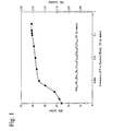
- Fig. 1 shows the change of a coercivity iHc of a sintered body having a composition by mass of 15.7% of Nd, 7.1 % of Pr, 7.5% of Dy, 1.1% of B, 2.0% of Co, 0.09% of Cu, 0.08% of Ga, and x % of P, the balance being Fe, relative to the content x of P in the sintered body.
- the improvement of the coercivity iHc is observed when the content of P reaches 0.0005% by mass, it is remarkable at the content of P of 0.001% or more by mass.
- the larger the content of P the higher the coercivity iHc.
- the strength of the sintered body is lowered. Accordingly, the content of Pin the sintered body is 0.001-0.05% by mass. In this range, no decrease in saturation magnetization is appreciated.
- the lower limit of the content of P is preferably 0.003% by mass, more preferably 0.008% by mass.
- the upper limit of the content of P is preferably 0.04% by mass, more preferably 0.02% by mass.
- methods for controlling the content of P may be (1) a method of mixing Fe alloys, starting material metals for an ingot for an R-Fe-B permanent magnet, with P-containing Fe-base alloys having known P contents, such as Fe-P alloys or Fe-B-P alloys, etc.
- the addition of such a sodium hypophosphite solution as to make the content of P less than 0.001% by mass provides only an insufficient effect of improving the fluidity of the slurry. It is preferable to control the amount of a solution of sodium hypophosphite in glycerin or ethanol, such that the ratio of sodium hypophosphite to a mineral oil, a synthetic oil or their mixture does not exceed 0.5% by mass.
- part of Fe may be replaced by at least one selected from the group consisting of Co, Nb, Al, Ga and Cu.
- the amount of each substituting element is expressed by percentage by mass per the overall sintered permanent magnet.
- the amount of Co is generally 0-5% or less by mass. Co functions to elevate the Curie temperature of the sintered magnet, namely, to improve the temperature coefficient of saturation magnetization. However, when the amount of Co exceeds 5% by mass, the sintered magnet has drastically decreased residual magnetic flux density Br and coercivity iHc.
- the amount of Co added is preferably 0.3-5% by mass, particularly 0.3-4.5% by mass. When the amount of Co is less than 0.3% by mass, there is only a small effect of improving the temperature coefficient.
- the amount of Nb is generally 0-1% by mass.
- a Nb boride formed in the sintering process suppresses the abnormal growth of crystal grains.
- the amount of Nb exceeds 1% by mass, a large amount of the Nb boride is formed, resulting in decrease in a residual magnetic flux density Br.
- the preferred amount of Nb replacing Fe is 0.05-1% by mass.
- the amount of Al is generally 0.01-1 % by mass.
- Al has an effect of increasing a coercivity iHc.
- the amount of Al is less than 0.01% by mass, there is only an insufficient effect of improving the coercivity iHc.
- the amount of Al exceeds 1% by mass, the residual magnetic flux density Br decreases drastically.
- the upper limit of the Al content is preferably 0.3% by mass.
- the amount of Ga is generally 0.01-0.5% by mass. Though a trace amount of Ga has an effect of improving a coercivity iHc, such effect would be insufficient if the amount of Ga were less than 0.01 % by mass. On the other hand, when the amount of Ga exceeds 0.5% by mass, the decrease of the residual magnetic flux density Br becomes remarkable, and the coercivity iHc also decreases.
- the amount of Ga is preferably 0.03-0.4% by mass, more preferably 0.03-0.2% by mass.
- the amount of Cu is generally 0-1% by mass. Though a trace amount of Cu has an effect of providing the sintered magnet with an improved coercivity iHc, such effect would be saturated if the amount of Cu added exceeded 1% by mass. When the amount of Cu added is less than 0.01 % by mass, there is only an insufficient effect of improving the coercivity iHc. Thus, the amount of Cu is preferably 0.01-1% by mass, more preferably 0.01-0.3% by mass.
- the sintered permanent magnet according to the first embodiment of the present invention has a composition comprising, by mass, 27-32% of R, 0.5-2% of B, 0.002-0.15% of N, 0.05-0.25% of O, 0.01-0.15% of C, and 0.001-0.05% of P, the balance being Fe.
- the sintered permanent magnet according to the illustrative example useful to understand the present invention has a composition comprising, by mass, more than 32% and 33.5% or less of R, 0.5-2% of B, 0.002-0.05% of N, more than 0.25% and 0.6% or less of O, 0.01-0.15% of C, and 0.001-0.05% of P, the balance being Fe.
- the sintered body having this composition can be produced from a slurry obtained by mixing dry fine powder pulverized in an atmosphere having an oxygen content of 0.005-0.5% with a mineral oil, a synthetic oil or their mixture.
- part of Fe may be replaced by at least one selected from the group consisting of 0.3-5% of Co, 0.05-1% of Nb, 0.01-1% of Al, 0.01-0.5% of Ga, and 0.01-1 % of Cu, by mass.
- Coarse powder having the above composition for an R-Fe-B permanent magnet is finely pulverized by a jet mill to fine powder having an average diameter of 3-6 ⁇ m, (a) in an atmosphere composed of a nitrogen gas and/or an Ar gas, whose oxygen content is substantially 0%, or (b) in an atmosphere composed of a nitrogen gas and/or an Ar gas, whose oxygen content is 0.005-0.5%.
- a trace amount of a nitrogen gas is preferably introduced into a jet mill whose atmosphere is an Ar gas, such that the concentration of a nitrogen gas in the Ar gas is adjusted.
- the jet mill When the jet mill is filled with a nitrogen gas atmosphere, it is preferable to control the amount of N mixed into magnet powder by adjusting the amount of coarse powder charged at the time of pulverization, thereby controlling the amount of N in the resultant sintered body.
- the phrase that "the oxygen concentration is substantially 0%" means that the present invention is not restricted to a case where the oxygen concentration is completely 0%, but includes a case where the fine powder may contain oxygen in such an amount that the fine powder surface is extremely slightly covered with an oxide layer.
- Such low oxygen concentration is, for instance, 0.001 % or less, preferably 0.0005% or less, more preferably 0.0002% or less.
- a vessel containing a mineral oil, a synthetic oil or their mixture is disposed at a fine powder-recovering outlet of the jet mill, and this vessel is filled with an atmosphere composed of a nitrogen gas and/or an Ar gas.
- the fine powder is recovered directly in a mineral oil, a synthetic oil or their mixture without contact with the air, to form a slurry.
- the mineral oil, the synthetic oil or their mixture is preferably mixed with sodium hypophosphite as a fluidity-improving agent.
- the sodium hypophosphite is preferably added in the form of a solution in glycerin or ethanol to a mineral oil, a synthetic oil or their mixture.
- the concentration of sodium hypophosphite in a solution in glycerin or ethanol is preferably such that the ratio of sodium hypophosphite to a mineral oil, a synthetic oil or their mixture is within a range of 0.01-0.5% by mass. When the ratio of sodium hypophosphite is less than 0.01% by mass, there is only an insufficient effect of improving the fluidity of the slurry.
- the radially anisotropic sintered R-Fe-B permanent magnet obtained from such slurry has an increased content of P.
- P exists mainly in a non-magnetic grain boundary phase rich in rare earth elements.
- the inventors' research has revealed that the ratio of sodium hypophosphite to a mineral oil, a synthetic oil or their mixture is preferably 0.01-0.5% by mass, such that the content of P in the sintered body is 0.001-0.05% by mass.
- the addition of a solution of sodium hypophosphite in glycerin or ethanol may be carried out before or after recovering the fine powder in a mineral oil, a synthetic oil or their mixture.
- the fine powder when the fine powder is mixed with a mineral oil, a synthetic oil or their mixture to form a slurry, the fine powder is prevented from oxidation and nitriding by the effect of a mineral oil, a synthetic oil or their mixture shielding the fine powder from the air. Accordingly, the contents of O and N in the resultant sintered body do not substantially differ from those in the fine powder.
- Fig. 2 shows an example of molding apparatuses used in the method of the present invention.
- a region indicated by the reference number 11 shows a vertical cross section of the molding apparatus, and a region indicated by the reference number 12 is a horizontal cross-sectional view showing a die in the molding apparatus, and its enlarged view (square region).
- the die comprises a solid cylindrical core 4, a hollow cylindrical die member 3, a lower punch 9, and an upper punch 10, a space enclosed by them being a cavity 6.
- the hollow cylindrical die member 3 is supported by a die case 2.
- a pair of magnetic field-generating coils 1 are disposed around the core 4 at its upper and lower positions, to apply magnetic fluxes 7 into the cavity 6 through the core 4.
- the die case 2 has a slurry-injecting aperture 5 open in the cavity 6.
- the axial direction of the slurry-injecting aperture 5 open in the die cavity, into which the slurry is injected under pressure, is preferably deviated from the center O of the center core 4 in the die.
- the fine powder slurry injected under pressure smoothly and substantially spirally fills up the ring-shaped cavity 6 along the outer circumferential surface of the core 4 or along the inner surface of the die without impinging the die core 4, resulting in a high filling density.
- an angle ⁇ (right or acute angle) between the center axis of the slurry-injecting aperture 5 and a radius of the die core 4 (straight line connecting a point A, at which the center axis of the slurry-injecting aperture 5 intersects the core 4, and the core center O) is 5° to 90°, preferably 10° to 90°, particularly 30° to 90°, though it may be slightly different depending on the size of the die cavity 6.
- the injection pressure of the slurry into the die cavity 6 is preferably 4.9 x 10 4 Pa to 3.9 x 10 6 Pa (about 0.5-40 kgf/cm 2 ), more preferably 9.8 x 10 4 Pa to 2.9 x 10 6 Pa (about 1-30 kgf/cm 2 ), particularly 2.0 x 10 5 Pa to 1.5 x 10 6 Pa (about 2-15 kgf/cm 2 ).
- the intensity of a radially oriented magnetic field applied into the die cavity 6 to orient the fine powder in the slurry is preferably 159 kA/m (about 2 kOe) or more, more preferably 239 kA/m (about 3 kOe) or more.
- wet molding is carried out under pressure while maintaining the oriented magnetic field.
- the intensity of the oriented magnetic field is less than 159 kA/m (about 2 kOe)
- the orientation of the fine powder is insufficient, failing to achieve good magnetic properties.
- the slurry may be wet-molded under pressure by applying a higher second oriented magnetic field than the first oriented magnetic field.
- the wet molding of the slurry with improved fluidity under the above conditions can provide a green body having as high a density as 4.0-4.8 g/cm 3 .
- the resultant green body is heated under a reduced pressure to remove a mineral oil, a synthetic oil or their mixture from the green body.
- the reduced-pressure heat treatment conditions of the green body are a vacuum degree of 13.3 Pa (about 0.1 Torr) or less, for instance, 6.7 Pa (about 5.0 x 10 -2 Torr), and a heating temperature of 100°C or higher, for instance, about 200°C.
- the heating time is preferably 1 hour or more, though it may differ depending on the weight and treatment degree of the green body.
- the sintering of the green body is carried out at a vacuum degree of 0.13 Pa (about 0.001 Torr) or less, preferably 6.7 x 10 -2 Pa (about 5.0 x 10 -4 Torr) or less, in a range of 1000-1150°C.
- a sintered body formed from a slurry of fine powder pulverized in an atmosphere having an oxygen content of substantially 0% has a density of 7.52-7.85 g/cm 3
- a sintered body formed from a slurry of fine powder pulverized in an atmosphere having an oxygen content of 0.005-0.5% has a density of 7.42-7.75 g/cm 3 .
- the content of O of the former sintered body is 0.05-0.25% by mass, and the content of O of the latter sintered body is more than 0.25% and 0.60% or less by mass.
- a radially oriented ring-shaped sintered permanent magnet having a size of an outer diameter of 10-100 mm, an inner diameter 8-96 mm, and a height of 10-70 mm.
- the present invention is particularly suitable for the production of small ring magnets having outer diameters of 10-30 mm, inner diameters 8-28 mm, and heights of 10-50 mm.
- the smooth filling of the slurry is conducted in an oriented magnetic field, it is possible to provide a green body having a high and uniform density and thus a ring magnet with a uniform distribution of a surface magnetic flux density in its axial direction.
- a cogging torque (particularly higher cogging torque) can be sufficiently suppressed when the ring magnet is used in a motor.
- the variation of a surface magnetic flux density is 5% or less, particularly 3% or less, extremely silent motors without energy loss can be obtained.
- the present invention will be specifically described below with reference to Examples without intention of restricting the scope of the present invention.
- the magnetic properties were measured at room temperature (25°C), and the average diameter of powder was measured by an air permeation method.
- the coarse powder was finely pulverized at a pressure of 6.9 x 10 5 Pa (about 7.0 kgf/cm 2 ) and at a coarse powder supply rate of 12 kg/hr.
- a container filled with a mineral oil was disposed at a fine powder-recovering outlet of the jet mill, to recover the resultant fine powder directly in the mineral oil in an Ar gas atmosphere.
- the resultant fine powder had an average diameter of 4.5 ⁇ m.
- This slurry was wet-molded in a die cavity under a pressure of 4.9 x 10 7 Pa (about 0.5 ton/cm 2 ), while applying an oriented magnetic field of 796 kA/m (about 10 kOe).
- the direction of the oriented magnetic field applied was perpendicular to the molding direction.
- the resultant green body was heated at 80°C in vacuum of 5.3 Pa (about 4.0 x 10 -2 Torr) for 2 hours to remove the mineral oil, and then sintered at 1065°C in vacuum of 6.7 x 10 -3 Pa (about 5.0 x 10 -5 Torr) for 4 hours.
- the composition of the resultant sintered body was, by mass, 17.5% of Nd, 7.7% of Pr, 5% of Dy, 1.1% of B, 0.08% of Al, 1.5% of Co, 0.1 % of Cu, 0.010% of P, 0.017% of O, 0.070% of C, and 0.045% of N, the balance being Fe.
- This sintered body was heat-treated at 480°C for 2 hours in an Ar gas atmosphere. As shown in Table 1, the measurement of the magnetic properties of the sintered magnet after machining indicated that it had good magnetic properties.
- Coarse powder was produced from an ingot having the same composition as in Example 1 except for containing no P in the same manner as in Example 1.
- the composition of this coarse powder was the same as in Example 1 except for containing no P and 0.14% by mass of O.
- This coarse powder was finely pulverized in the same manner as in Example 1.
- the resultant fine powder had an average diameter of 4.5 ⁇ m.
- the composition analysis of a sintered body formed from this fine powder in the same manner as in Example 1 indicated that the sintered body had a composition by mass of 17.5% of Nd, 7.7% of Pr, 5% of Dy, 1.1% of B, 0.08% of Al, 1.5% of Co, 0.1% of Cu, 0.16% of O, 0.070% of C, and 0.045% of N, the balance being Fe.
- This sintered body was machined to measure its magnetic properties. The results are shown in Table 1. Table 1 indicates that the coercivity iHc of the sintered body was lower in Comparative Example 1 than in Example 1.
- composition analysis of a sintered body formed from this fine powder in the same manner as in Example 1 indicated that it had a composition by mass of 19.7% of Nd, 8.8% of Pr, 1.3% of Dy, 1.1 % of B, 0.10% of Al, 2.5% of Co, 0.2% of Nb, 0.08% of Ga, 0.008% of P, 0.18% of O, 0.067% of C, and 0.055% ofN, the balance being Fe.
- This sintered body was machined to measure its magnetic properties, which were good as shown in Table 1.
- Example 2 100 kg of the same coarse powder as in Example 2 was finely pulverized in the same manner as in Example 1 except for adding no aqueous solution of sodium hypophosphite.
- the resultant fine powder had an average diameter of 4.7 ⁇ m.
- the composition analysis of a sintered body formed from this fine powder in the same manner as in Example 1 indicated that it had a composition by mass of 19.7% of Nd, 8.8% of Pr, 1.3% of Dy, 1.1 % of B, 0.10% of Al, 2.5% of Co, 0.2% of Nb, 0.08% of Ga, 0.16% of O, 0.067% of C, and 0.050% of N, the balance being Fe.
- This sintered body was machined to measure its magnetic properties.
- the coercivity iHc of this sintered body was lower than that of Example 2 as shown in Table 1.
- a mineral oil (“Super Sol PA30,” available from Idemitsu Kosan Co., Ltd.
- This mineral oil was mixed with a 5-%-by-mass solution of sodium hypophosphite in glycerin in advance, such that the ratio of sodium hypophosphite to the mineral oil was 0.1 % by mass.
- a mass ratio of the mineral oil to the fine powder in the slurry was 1:3.
- the resultant fine powder had an average diameter of 4.5 ⁇ m.
- the slurry thus produced was injected under pressure into a cavity of a die provided with coils for generating an oriented magnetic field as shown in Fig. 2 , to carry out molding.
- An angle ⁇ between the axial direction of the slurry-injecting aperture 5 and a radial direction of the die core 4 was 30°.
- the intensity of a radially oriented magnetic field applied to the cavity was 239 kA/m (3 kOe), and the slurry injection pressure was 3.9 x 10 5 Pa (4 kgf/cm 2 ).
- wet molding was conducted under a pressure of 7.8 x 10 7 Pa (0.8 ton/cm 2 ) in an oriented magnetic field whose intensity was maintained at 239 kA/m (3 kOe), to form a green body having an outer diameter of 24.5 mm, an inner diameter of 17.4 mm and a height of 30.0 mm.
- the density of the green body was 4.30 g/cm 3 .
- This green body was subjected to an oil-removing treatment at 200°C under a reduced pressure of 6.7 Pa (5 x 10 -2 Torr) for 2 hours, and then sintered at 1050°C under a reduced pressure of 2.7 x 10 -2 Pa (2 x 10 -4 Torr) for 3 hours.
- the resultant sintered body had a size of an outer diameter of 20.0 mm, an inner diameter of 15.0 mm and a height of 26.0 mm, and a density of 7.58 g/cm 3 .
- the sintered body was finished by machining to a size of an outer diameter of 19.6 mm, an inner diameter of 15.4 mm and a height of 25.0 mm.
- the surface magnetic flux density of the sintered body was measured. As a result, high peak values were observed as shown in Table 3.
- test piece 21b of 5 mm x 7 mm x 1 mm (1-mm thickness direction aligned with a magnetization direction) was cut out from the sintered body 20 as shown in Fig. 3 .
- the reference numeral 21 denotes a test piece before cutting.
- the measurement of the magnetic properties of eight test pieces 21b stacked in a thickness direction indicated that the test piece had high magnetic properties as shown in Table 3.
- composition analysis of this sintered body indicated that it had a composition by mass of 19.85% of Nd, 8.95% of Pr, 1.00% of Dy, 1.02% of B, 0.10% of Al, 2.00% of Co, 0.10% of Cu, 0.17% of O, 0.06% of C, 0.05% of N, and 0.01% of P, the balance being Fe.
- the peaks of P were observed as shown in Fig. 4 . It is clear from Fig. 4 that P existed mainly in a rare earth-rich phase of crystal grain boundaries.
- Example 3 The same coarse powder as in Example 3 was finely pulverized in the same manner as in Example 3 and recovered in a mineral oil ("Super Sol PA30," available from Idemitsu Kosan Co., Ltd.) to form a slurry.
- the mass ratio of the mineral oil to the fine powder was 1:3.
- the resultant fine powder had an average diameter of 4.8 ⁇ m.
- This slurry was mixed with a 10-%-by-mass solution of sodium hypophosphite in ethanol, such that the ratio of sodium hypophosphite to the mineral oil was 0.3% by mass.
- the resultant slurry was injected under pressure into a die cavity, in which an angle ⁇ between the axis of a slurry-injecting aperture and a radius of a die core was 5°, and wet-molded in a magnetic field in the same manner as in Example 3, to obtain a green body of an outer diameter of 24.5 mm, an inner diameter of 17.4 mm and a height of 30.0 mm.
- the density of the green body was 4.40 g/cm 3 .
- This green body was subjected to oil removal and sintering in the same manner as in Example 3, to obtain a sintered body of an outer diameter of 20.1 mm, an inner diameter of 14.9 mm and a height of 26.2 mm.
- the density of the sintered body was 7.56 g/cm 3 .
- This sintered body was heat-treated at 500°C for 2 hours.
- This sintered body was finished by machining to a size of an outer diameter of 19.6 mm, an inner diameter of 15.4 mm and a height of 25.0 mm, and magnetized to have four magnetic poles in the same manner as in Example 3.
- the surface magnetic flux density of the sintered body was measured. As a result, high peak values were observed as shown in Table 3.
- a test piece 21b was cut out from this sintered body as shown in Fig. 3 .
- the position of cutting the test piece 21b and the conditions of measuring its size and magnetic properties were the same as in Example 3. Good magnetic properties as shown in Table 3 were appreciated.
- the composition analysis of the sintered body indicated that it had a composition by mass of 19.85% of Nd, 8.95% of Pr, 1.00% of Dy, 1.02% of B, 0.10% of Al, 2.00% of Co, 0.10% of Cu, 0.16% of O, 0.06% of C, 0.04% of N, and 0.03% of P, the balance being Fe.
- the peaks of P were appreciated as shown in Fig. 5 .
- the slurry produced in Example 3 was injected under pressure into a die cavity, to which a radially oriented magnetic field of 239 kA/m (3 kOe) was applied, and wet-molded in a magnetic field in the same manner as in Example 3.
- the slurry injection pressure was 3.9 x 10 5 Pa (4 kgf/cm 2 ).
- the intensity of the oriented magnetic field was increased to 398 kA/m (5 kOe) after 0.5 seconds from the start of slurry injection, and wet molding was conducted while keeping this intensity of the magnetic field after the completion of slurry injection, to obtain a green body of an outer diameter of 24.5 mm, an inner diameter of 17.4 mm and a height of 30.0 mm.
- the density of the green body was 4.25 g/cm 3 .
- This green body was subjected to oil removal and sintering in the same manner as in Example 3, to obtain a sintered body of an outer diameter of 19.9 mm, an inner diameter of 15.1 mm and a height of 26.1 mm.
- the density of the sintered body was 7.59 g/cm 3 .
- This sintered body was heat-treated in the same manner as in Example 3, and machined to a size of an outer diameter of 19.6 mm, an inner diameter of 15.4 mm and a height of 25.0 mm.
- the resultant product was magnetized to have four magnetic poles, and its surface magnetic flux density was measured in the axial direction of a magnetic pole. Table 3 shows that it had a good surface magnetic flux density.
- the measurement of the magnetic properties of a test piece cut out in the same manner as in Example 3 indicated that it had high magnetic properties as shown in Table 3.
- Example 3 The slurry produced in Example 3 was injected under pressure into a die cavity, in which an angle ⁇ between the axis of the slurry-injecting aperture and the radius of the die core was 45°, and wet-molded in a magnetic field in the same manner as in Example 3.
- the die was changed to one for a large-diameter ring magnet.
- the intensity of a radially oriented magnetic field applied to the cavity was 478 kA/m (about 6 kOe), and the injection pressure was 5.9 x 10 5 Pa (about 6 kgf/cm 2 ).
- wet molding was conducted under a pressure of 4.9 x 10 7 Pa (0.5 ton/cm 2 ) in an oriented magnetic field whose intensity was maintained at 478 kA/m (about 6 kOe), to obtain a green body of an outer diameter of 114.0 mm, an inner diameter of 95.0 mm and a height of 20.5 mm.
- the density of the green body was 4.28 g/cm 3 .
- This green body was subjected to oil removal and sintering in the same manner as in Example 3, to obtain a sintered body of an outer diameter of 92.5 mm, an inner diameter of 81.5 mm and a height of 18 mm.
- the density of the sintered body was 7.57 g/cm 3 .
- the sintered body was heat-treated at 500°C for 2 hours.
- This sintered body was finished by machining to a size of an outer diameter of 91.5 mm, an inner diameter of 80.5 mm and a height of 16 mm.
- the sintered body was magnetized to have 16 magnetic poles, and measured with respect to a surface magnetic flux density in the axial direction of a magnetic pole. As a result, it was confirmed that it had a good surface magnetic flux density as shown in Table 3.
- Four test pieces of 5 mm x 10 mm x 2 mm cut out from the sintered body were stacked in a thickness direction to measure their magnetic properties. As a result, it was confirmed that they had high magnetic properties as shown
- Example 3 The slurry produced in Example 3 was injected under pressure into a die cavity, in which an angle ⁇ between the axis of the slurry-injecting aperture and the radius of the die core was 15°, and wet-molded in a magnetic field in the same manner as in Example 3.
- the die was changed to one for a middle-diameter, long ring magnet.
- the intensity of a radially oriented magnetic field applied to the cavity was 199 kA/m (about 2.5 kOe), and the injection pressure was 2.0 x 10 5 Pa (about 2 kgf/cm 2 ).
- the intensity of the oriented magnetic field was increased to 637 kA/m (8 kOe), and wet molding was conducted under a pressure of 3.9 x 10 7 Pa (0.4 ton/cm 2 ) in a magnetic field with intensity maintained at the above level, to obtain a green body of an outer diameter of 50 mm, an inner diameter of 40 mm and a height of 76 mm.
- the density of the green body was 4.15 g/cm 3 .
- This green body was subjected to oil removal and sintering in the same manner as in Example 3, to obtain a sintered body of an outer diameter of 40.4 mm, an inner diameter of 35.0 mm and a height of 65.2 mm.
- the density of the sintered body was 7.59 g/cm 3 .
- the sintered body was heat-treated at 500°C for 2 hours.
- This sintered body was finished by machining to a size of an outer diameter of 40.0 mm, an inner diameter of 35.4 mm and a height of 64.2 mm.
- the sintered body was magnetized to have 8 magnetic poles, and its surface magnetic flux density was measured in the axial direction of a magnetic pole. As a result, it was confirmed that it had good surface magnetic flux density as shown in Table 3.
- Eight test pieces of 5 mm x 8 mm x 1 mm cut out from the sintered body were stacked in a thickness direction to measure their magnetic properties. As a result, it was confirmed that they had high magnetic properties as shown in Table 3.
- Example 3 The same coarse powder as in Example 3 was finely pulverized in the same manner as in Example 3, and the resultant fine powder was recovered in a mineral oil ("Super Sol PA30," available from Idemitsu Kosan Co., Ltd.) to form a slurry.
- the mass ratio of the mineral oil to the fine powder was 1:3.
- the average diameter of the fine powder was 4.5 ⁇ m.
- the mineral oil was mixed with a 5-%-by-mass solution of sodium hypophosphite in glycerin in advance, such that the ratio of sodium hypophosphite to the mineral oil was 1% by mass.
- the resultant slurry was injected under pressure into a die cavity and wet-molded in a magnetic field in the same manner as in Example 3, to obtain a green body of an outer diameter of 24.5 mm, an inner diameter of 17.4 mm and a height of 30.0 mm.
- the density of the green body was 4.35 g/cm 3 .
- This green body was subjected to oil removal and sintering in the same manner as in Example 3, to obtain a sintered body of an outer diameter of 20.2 mm, an inner diameter of 15.1 mm and a height of 25.9 mm.
- the density of the sintered body was 7.58 g/cm 3 .
- the sintered body was heat-treated at 500°C for 2 hours. Though it was tried to machine this sintered body, the sintered body was broken by a load during working because of its low mechanical strength, resulting in failure to evaluation. Eight test pieces of 5 mm x 7 mm x 1 mm cut out from a broken piece of the sintered body was stacked in a thickness direction to measure their magnetic properties. The results are shown in Tables 2 and 3.
- the composition analysis of the sintered body indicated that it had a composition by mass of 19.85% of Nd, 8.95% of Pr, 1.00% of Dy, 1.02% of B, 0.10% of Al, 2.00% of Co, 0.10% of Cu, 0.16% of O, 0.07% of C, 0.04% of N, and 0.09% of P, the balance being Fe.
- Example 3 The same coarse powder as in Example 3 was finely pulverized in the same manner as in Example 3, and the resultant fine powder was recovered in a mineral oil ("Super Sol PA30," available from Idemitsu Kosan Co., Ltd.) to form a slurry.
- the mass ratio of the mineral oil to the fine powder was 1:3.
- the average diameter of the fine powder was 4.5 ⁇ m.
- No fluidity-improving agent a solution of sodium hypophosphite in glycerin or ethanol was added to any of the mineral oil and the slurry. This slurry was injected under pressure into a die cavity and wet-molded in a magnetic field in the same manner as in Example 3.
- the resultant green body had a size of an outer diameter of 24.5 mm, an inner diameter of 17.4 mm and a height of 26.5 mm.
- the density of the green body was 3.80 g/cm 3 .
- This green body was subjected to oil removal and sintering in the same manner as in Example 3, to obtain a sintered body of an outer diameter of 19.7 mm, an inner diameter of 14.8 mm and a height of 23.3 mm.
- the density of the sintered body was 7.57 g/cm 3 . Because of a poor filling ratio of the slurry on the side of an upper punch, the sintered body was deformed to an elliptical shape on the side of the upper punch. Because of the deformation, the sintered body could not be machined to a desired product size.
- the sintered body was heat-treated at 500°C for 2 hours, and a test piece of 5 mm x 7 mm x 1 mm was cut out from a deformation-free portion of the sintered body. Eight test pieces were stacked in a thickness direction to measure their magnetic properties. The results are shown in Table 3.
- the composition analysis of the sintered body indicated that it had a composition by mass of 19.85% of Nd, 8.95% of Pr, 1.00% of Dy, 1.02% of B, 0.10% of Al, 2.00% of Co, 0.10% of Cu, 0.16% of O, 0.07% of C, and 0.06% of N, the balance being Fe.
- the line analysis of EPMA of this sintered body indicated that there were no peaks of P as shown in Fig. 6 , unlike the sintered bodies of Examples 3 and 4.
- the density of the green body was 4.29 g/cm 3 .
- This green body was subjected to oil removal and sintering in the same manner as in Example 3, to obtain a sintered body of an outer diameter of 20.1 mm, an inner diameter of 15.1 mm and a height of 25.9 mm.
- the density of the sintered body was 7.60 g/cm 3 .
- the resultant sintered body had longitudinal cracks at a position opposite to the injection aperture by 180°. Because of the cracks, this sintered body could not be machined to a desired size.
- Eight test pieces of 5 mm x 7 mm x 1 mm cut out from a cracks-free portion of the sintered body were stacked in a thickness direction to measure their magnetic properties. The results are shown in Table 3.
- Example 3 The slurry produced in Example 3 was injected under pressure into a die cavity, and wet-molded in an oriented magnetic field of 79.6 kA/m (1.0 kOe) in the same manner as in Example 3, to obtain a green body of an outer diameter of 24.5 mm, an inner diameter of 17.4 mm and a height of 30.0 mm.
- the density of the green body was 4.32 g/cm 3 .
- This green body was subjected to oil removal and sintering in the same manner as in Example 3, to obtain a sintered body of an outer diameter of 20.3 mm, an inner diameter of 15.2 mm and a height of 25.8 mm.
- the density of the sintered body was 7.59 g/cm 3 .
- This sintered body was heat-treated at 500°C for 2 hours.
- This sintered body was finished by machining to a size of an outer diameter of 19.6 mm, an inner diameter of 15.4 mm and a height of 25.0 mm. After forming four magnetic poles by magnetization, the surface magnetic flux density was measured. As a result, the peak value was lower than Example 3 as shown in Table 3. Eight test pieces of 5 mm x 7 mm x 1 mm cut out from the sintered body were stacked in a thickness direction to measure their magnetic properties. As a result, it was confirmed that the magnetic properties were lower than those of Example 3 as shown in Table 3.
- Coarse powder for an R-Fe-B permanent magnet having a composition by mass of 22.00% of Nd, 5.50% of Pr, 5.00% of Dy, 1.03% of B, 0.08% of Al, 1.00% of Co, 0.12% of Cu, 0.10% of Ga, 0.09% of O, 0.03% of C, and 0.015% of N, the balance being Fe, was charged into a jet mill. After replacing an atmosphere in the jet mill with a nitrogen gas, the coarse powder was finely pulverized at pressure of 6.4 x 10 5 Pa (6.5 kgf/cm 2 ) and at a coarse powder supply rate of 20 kg/hr.
- the resultant fine powder had a particle size of 5.0 ⁇ m.
- the composition of the fine powder was, by mass, 22.00% of Nd, 5.50% of Pr, 5.00% of Dy, 1.03% of B, 0.08% of Al, 1.00% of Co, 0.12% of Cu, 0.10% of Ga, 0.48% of O, 0.06% of C, and 0.015% of N, the balance being Fe.
- This fine powder was mixed with a mineral oil ("Super Sol PA30,” available from Idemitsu Kosan Co., Ltd.) to form a slurry.
- the mineral oil contained a 5-%-by-mass solution of sodium hypophosphite in glycerin, such that the ratio of sodium hypophosphite to the mineral oil 0.2% by mass.
- the mass ratio of the fine powder to the mineral oil was 1:3.
- the resultant slurry was injected under pressure into a ring-shaped die cavity, to which a radially oriented magnetic field was applied, and wet-molded in the same manner as in Example 3, to obtain a green body of an outer diameter of 24.5 mm, an inner diameter of 17.4 mm and a height of 30.0 mm.
- the density of the green body was 4.45 g/cm 3 .
- This green body was sintered at 1070°C under a reduced pressure of 6.7 Pa (5 x 10 -5 Torr) for 3 hours, to obtain a sintered body of an outer diameter of 20.3 mm, an inner diameter of 15.1 mm and a height of 25.8 mm.
- the density of the sintered body was 7.61 g/cm 3 .
- the sintered body was heat-treated at 550°C for 2 hours.
- This sintered body was machined to a size of an outer diameter of 19.6 mm, an inner diameter of 15.4 mm and a height of 25.0 mm, and magnetized to have 8 magnetic poles.
- the measurement results of a surface magnetic flux density are shown in Table 3.
- Magnetic properties were measured on a test piece having the same size as in Example 3 cut out from the sintered body. As a result, it was confirmed that it had good magnetic properties as shown in Table 3.
- the composition analysis of the sintered body indicated that it had a composition by mass of 22.00% of Nd, 5.50% of Pr, 5.00% of Dy, 1.03% of B, 0.08% of Al, 1.00% of Co, 0.12% of Cu, 0.10% of Ga, 0.46% of O, 0.06% of C, 0.015% of N, and 0.02% of P, the balance being Fe.
- Dry fine powder produced in Example 8 was filled in the same die cavity as in Example 8 without mixing with a mineral oil, and molded in an oriented magnetic field of 239 kA/m (3 kOe) under a reduced pressure of 7.8 x 10 7 Pa (0.8 ton/cm 2 ), to produce a green body of an outer diameter of 24.5 mm, an inner diameter of 17.4 mm and a height of 30.0 mm.
- the density of the green body was 3.78 g/cm 3 .
- This green body was sintered at 1070°C under a reduced pressure of 2.7 Pa (2 x 10 -5 Torr) for 3 hours, to obtain a sintered body of an outer diameter of 20.1 mm, an inner diameter of 15.0 mm and a height of 25.9 mm.
- the density of the sintered body was 7.59 g/cm 3 .
- This sintered body was heat-treated at 550°C for 2 hours, and then machined to a size of an outer diameter of 19.6 mm, an inner. diameter of 15.4 mm and a height of 25.0 mm.
- This sintered body was magnetized to have 8 magnetic poles, and its surface magnetic flux density was measured in the axial direction of a magnetic pole. As a result, it was confirmed that it had a lower surface magnetic flux density than that of Example 8 as shown in Table 3.
- Eight test pieces of 5 mm x 7 mm x 1 mm cut out from the sintered body were stacked in a thickness direction to measure their magnetic properties. As a result, it was confirmed that they had lower magnetic properties than those of Example 8 as shown in Table 3.
- Example 8 Dry fine powder produced in Example 8 was charged into the die cavity of Example 8 from above without mixing with a mineral oil, and molded under a pressure of 7.8 x 10 7 Pa (0.8 ton/cm 2 ) in an oriented magnetic field of 318 kA/m (4 kOe) to produce a first green body of an outer diameter of 24.5 mm, an inner diameter of 17.4 mm and a height of 10.0 mm.
- This integral green body was sintered at 1070°C under a reduced pressure of 6.7 Pa (5.0 x 10 -5 Torr) for 3 hours, to obtain a sintered body of an outer diameter of 20.0 mm, an inner diameter of 14.9 mm and a height of 26.1 mm.
- the density of the sintered body was 7.58 g/cm 3 .
- the sintered body was heat-treated at 550°C for 2 hours, and machined to a size of an outer diameter of 19.6 mm, an inner diameter of 15.4 mm and a height of 25.0 mm.
- This sintered body was magnetized to have 8 magnetic poles, and its surface magnetic flux density was measured in the axial direction of a magnetic pole.
- Coarse powder for an R-Fe-B permanent magnet having a composition by mass of 20.50% of Nd, 9.25% of Pr, 0.25% of Dy, 1.03% of B, 0.08% of Al, 2.00% of Co, 0.10% of Cu, 0.13% of O, 0.04% of C, and 0.02% of N, the balance being Fe, was charged into a jet mill. After replacing an atmosphere in the jet mill with a nitrogen gas, the coarse powder was finely pulverized at a pressure of 6.9 x 10 5 Pa (7.0 kgf/cm 2 ) and at a coarse powder supply rate of 20 kg/hr. The resultant fine powder was recovered directly in a mineral oil ("Super Sol PA30,” available from Idemitsu Kosan Co., Ltd.) disposed at an outlet of the jet mill without contact with the air, to form a slurry.
- a mineral oil (“Super Sol PA30,” available from Idemitsu Kosan Co., Ltd.
- This mineral oil was mixed with a 5-%-by-mass solution of sodium hypophosphite in glycerin in advance, such that the ratio of sodium hypophosphite to the mineral oil was 0.2% by mass.
- the mass ratio of the fine powder to the mineral oil was 1:3.
- the average diameter of the fine powder was 4.7 ⁇ m.
- the slurry thus produced was injected under pressure into a die shown in Fig. 2 , in which an angle ⁇ between the axis of a slurry-injecting aperture 5 and a radius of a die core 4 was 45°.
- the intensity of a radially oriented magnetic field applied to the cavity was 239 kA/m (about 3 kOe), and the slurry injection pressure was 2.9 x 10 5 Pa (about 3 kgf/cm 2 ).
- wet molding was conducted under a pressure of 3.9 x 10 7 Pa (about 0.4 ton/cm 2 ) in an oriented magnetic field whose intensity was maintained at 239 kA/m (about 3 kOe), to obtain a green body of an outer diameter of 25.3 mm, an inner diameter of 17.5 mm and a height of 21.8 mm.
- the density of the green body was 4.40 g/cm 3 .
- This green body was subjected to an oil-removing treatment at 180°C under a reduced pressure of 6.7 Pa (about 5.0 x 10 -2 Torr) for 4 hours, and then sintered at 1040°C under a reduced pressure of 6.7 x 10 -2 Pa (about 5.0 x 10 -4 Torr) for 3 hours.
- the resultant sintered body had a size of an outer diameter of 20.6 mm, an inner diameter of 15.3 mm and a height of 18.8 mm and a density of 7.56 g/cm 3 .
- the sintered body was heat-treated at 480°C for 2 hours. This sintered body was finished by machining to a size of an outer diameter of 20.1 mm, an inner diameter of 15.9 mm and a height of 17.2 mm.
- a yield (the weight of the sintered body after working / the weight of the sintered body before working) x 100%] was 72.7%. The yield may be called "working ratio.”
- the surface magnetic flux density B 0 of the ring magnet magnetized to have four magnetic poles was measured by a hole sensor probe in the axial direction of a magnetic pole on an outer circumferential surface of the ring magnet.
- the peak value (maximum) of the surface magnetic flux density B 0 , and the variation of the surface magnetic flux density B 0 which was represented by [(maximum of B 0 - minimum of B 0 ) / maximum of B 0 ] x 100 (%), were determined from the measurement results of the surface magnetic flux density B 0 .
- the results are shown in Table 5 and Fig. 7 . In Fig.
- the ordinate axis indicates a surface magnetic flux density B 0 (T) in the axial direction of a magnetic pole of the ring magnet
- the abscissa axis indicates a distance (mm) that the probe moved in the axial direction of the ring magnet.
- the distance H corresponds to the length (17.2 mm) of the ring magnet in its axial direction.
- the surface magnetic flux density B 0 had a high peak value and a small variation.
- test pieces 21b of 4 mm x 7 mm x 1 mm were cut out from the sintered body 20 produced in the same manner, as shown in Fig. 3 and stacked in a thickness direction to measure their magnetic properties. As a result, it was confirmed that they had high magnetic properties as shown in Table 5.
- the composition analysis of the sintered body indicated that it had a composition by mass of 20.50% of Nd, 9.25% of Pr, 0.25% Dy, 1.03% of B, 0.08% of Al, 2.00% of Co, 0.10% of Cu, 0.15% of O, 0.06% of C, 0.05% of N, and 0.018% of P, the balance being Fe.
- the line analysis of EPMA of the test piece 21b indicated that there were peaks of P as shown in Fig. 8 . It is clear from Fig. 8 that P existed mainly in a rare earth-rich phase of crystal grain boundaries.
- Example 9 The same coarse powder as in Example 9 was finely pulverized and recovered in a mineral oil ("Super Sol PA30," available from Idemitsu Kosan Co., Ltd.) in the same manner as in Example 9, to form a slurry.
- the mass ratio of the mineral oil to the fine powder was 1:3.
- the resultant fine powder had an average diameter of 4.6 ⁇ m.
- This slurry was mixed with a 10-%-by-mass solution of sodium hypophosphite in ethanol, such that the ratio of sodium hypophosphite to the mineral oil was 0.4% by mass.
- This slurry was injected under pressure into a die cavity, in which an angle ⁇ between the axis of the slurry-injecting aperture and the radius of the die core was 30°, and wet-molded in a magnetic field in the same manner as in Example 9, to obtain a green body of an outer diameter of 25.3 mm, an inner diameter of 17.5 mm and a height of 21.8 mm.
- the density of the green body was 4.35 g/cm 3 .
- 123 green bodies were thus produced per one hour.
- the yield of the product was 72.9%.
- This green body was subjected to oil removal and sintering in the same manner as in Example 9 to obtain a sintered body of an outer diameter of 20.6 mm, an inner diameter of 15.3 mm and a height of 18.75 mm.
- the density of the sintered body was 7.55 x g/cm 3 .
- This sintered body was heat-treated at 480°C for 2 hours.
- This sintered body was finished by machining to a size of an outer diameter of 20.1 mm, an inner diameter of 15.9 mm and a height of 17.2 mm.
- the surface magnetic flux density B 0 was measured in the axial direction of a magnetic pole in the same manner as in Example 9. As a result, it was confirmed that the surface magnetic flux density B 0 had a high peak value as shown in Table 5.
- the calculation of the variation of the surface magnetic flux density B 0 in an axial direction indicated that it was small as shown in Table 5.
- a test piece was cut out from the sintered body in the same manner as in Example 9.
- the measurement results of magnetic properties are shown in Table 5.
- the composition analysis of the sintered body indicated that it had a composition by mass of 20.50% of Nd, 9.25% of Pr, 0.25% of Dy, 1.03% of B, 0.08% of Al, 2.00% of Co, 0.10% of Cu, 0.16% of O, 0.07% of C, 0.06% of N, and 0.037% of P, the balance being Fe.
- the peaks of P were confirmed as shown in Fig. 9 .
- Example 9 The slurry produced in Example 9 was injected under pressure into a die cavity, in which an angle ⁇ between the axis of the slurry-injecting aperture and the radius of the die core was 60°, and wet-molded in a magnetic field in the same manner as in Example 9.
- the size of the die cavity was changed.
- the intensity of a radially oriented magnetic field applied to the cavity was 398 kA/m (about 5 kOe), and the injection pressure was 5.9 x 10 5 Pa (about 6 kgf/cm 2 ).
- wet molding was conducted under a pressure of 7.8 x 10 7 Pa (about 0.8 ton/cm 2 ) in an oriented magnetic field, whose intensity was maintained at 398 kA/m (about 5 kOe), to obtain a green body of an outer diameter of 33.4 mm, an inner diameter of 24.3 mm and a height of 55.1 mm. 125 green bodies were produced per one hour. The density of the green body was 4.45 g/cm 3 .
- This green body was subjected to oil removal and sintering in the same manner as in Example 9, to obtain a sintered body of an outer diameter of 27.4 mm, an inner diameter of 21.1 mm and a height of 47.4 mm.
- the density of the sintered body was 7.57 g/cm 3 .
- the sintered body was heat-treated at 480°C for 2 hours. This sintered body was finished by machining to a size of an outer diameter of 26.8 mm, an inner diameter of 21.8 mm and a height of 45.0 mm.
- the yield of the product was 75.5%.
- the sintered body was magnetized to have four magnetic poles, and its surface magnetic flux density was measured in the axial direction of a magnetic pole.
- the surface magnetic flux density had a high peak value and small variation as shown in Table 5.
- Eight test pieces of 4 mm x 7 mm x 1 mm cut out from the sintered body were stacked in a thickness direction to measure their magnetic properties. As a result, it was confirmed that they had high magnetic properties as shown in Table 5.
- Example 11 The slurry produced in Example 11 was injected under a pressure of 3.9 x 10 5 Pa (about 4 kgf/cm 2 ) into a die cavity, to which a radially oriented magnetic field of 159 kA/m (about 2 kOe) was applied, and wet-molded in a magnetic field in the same manner as in Example 11.
- the intensity of the oriented magnetic field was increased to 318 kA/m (about 4 kOe), and after injecting, wet molding was conducted in a magnetic field, whose intensity was kept to the above level, to obtain a green body of an outer diameter of 33.4 mm, an inner diameter of 24.3 mm and a height of 54.8 mm.
- the density of the green body was 4.45 g/cm 3 . 121 green bodies were produced per one hour.
- This green body was subjected to oil removal and sintering in the same manner as in Example 9, to obtain a sintered body of an outer diameter of 27.4 mm, an inner diameter of 21.1 mm and a height of 47.1 mm.
- the density of the sintered body was 7.57 g/cm 3 .
- This sintered body was heat-treated in the same manner as in Example 9, and machined to a size of an outer diameter of 26.8 mm, an inner diameter of 21.8 mm and a height of 45.0 mm.
- the yield of the product was 6.0%.
- the surface magnetic flux density B 0 was measured. As a result, the surface magnetic flux density B 0 had a high peak value and a small variation as shown in Table 5.
- the test piece cut out in the same manner as in Example 9 had high magnetic properties as shown in Table 5.
- Example 9 The slurry produced in Example 9 was injected under pressure into a die cavity, in which an angle ⁇ between the axis of the slurry-injecting aperture and the radius of the die core was 15°, and wet-molded in a magnetic field in the same manner as in Example 9.
- the size of the die cavity was changed.
- the intensity of the radially oriented magnetic field applied to the cavity was 223 kA/m (2.8 kOe), and the injection pressure was 3.9 x 10 5 Pa (about 4 kgf/cm 2 ).
- wet molding was conducted under a pressure of 3.9 x 10 7 Pa (about 0.4 ton/cm 2 ) in an oriented magnetic field, whose intensity was kept at 223 kA/m (2.8 kOe), to obtain a green body of an outer diameter of 17.9 mm, an inner diameter of 11.1 mm and a height of 16.4 mm.
- the density of the green body was 4.40 g/cm 3 . 140 green bodies were produced per one hour.
- This green body was subjected to oil removal and sintering in the same manner as in Example 9, to obtain a sintered body of an outer diameter of 14.6 mm, an inner diameter of 9.6 mm and a height of 14.2 mm.
- the density of the sintered body was 7.58 g/cm 3 .
- the sintered body was heat-treated at 480°C for 2 hours. This sintered body was finished by machining to a size of an outer diameter of 14.0 mm, an inner diameter of 10.0 mm and a height of 12.5 mm.
- the yield of the product was 69.8%.
- the sintered body was magnetized to have four magnetic poles, and its surface magnetic flux density was measured in the axial direction of a magnetic pole. As a result, the surface magnetic flux density had a high peak value and a small variation as shown in Table 5. Eight test pieces of 3 mm x 7 mm x 1 mm cut out from the sintered body were stacked in a thickness direction to measure their magnetic properties. As a result, it was confirmed that they had high magnetic properties as shown in Table 5.
- Example 9 The same coarse powder as in Example 9 was finely pulverized and recovered in a mineral oil ("Super Sol PA30," available from Idemitsu Kosan Co., Ltd.) in the same manner as in Example 9, to form a slurry.
- the mass ratio of the mineral oil to the fine powder was 1:3.
- the resultant fine powder had an average diameter of 4.6 ⁇ m. Any of the mineral oil and the slurry was not mixed with a solution of sodium hypophosphite in glycerin or ethanol. This slurry was injected under pressure and wet-molded in a magnetic field in the same manner as in Example 9.
- the resultant green body had a size of an outer diameter of 25.3 mm, an inner diameter of 17.5 mm and a height of 19.5 mm.
- the density of the green body was 3.85 g/cm 3 . 116 green bodies were produced per one hour.
- This green body was subjected to oil removal and sintering in the same manner as in Example 9 to obtain a sintered body of an outer diameter of 20.3 mm, an inner diameter of 15.0 mm and a height of 15.9 mm.
- the density of the sintered body was 7.55 g/cm 3 .
- the resultant sintered body was deformed to an elliptical shape in a portion on the side of the upper punch, and thus the sintered body could not be machined to a product size.
- the sintered body was heat-treated at 480°C for 2 hours, and eight test pieces of 4 mm x 7 mm x 1 mm cut out from other portions than the deformed portion were stacked in a thickness direction to measure their magnetic properties.
- the results are shown in Table 5.
- the composition analysis of the sintered body indicated that it had a composition by mass of 20.50% of Nd, 9.25% of Pr, 0.25% of Dy, 1.03% of B, 0.08% of Al, 2.00% of Co, 0.10% of Cu, 0.15% of O, 0.07% of C, and 0.05% of N, the balance being Fe.
- the line analysis of EPMA of this sintered body revealed that there were no peaks of P as shown in Fig. 10 .
- the density of the green body was 4.38 g/cm 3 . 118 green bodies were produced per one hour.
- This green body was subjected to oil removal and sintering in the same manner as in Example 9 to obtain a sintered body of an outer diameter of 20.6 mm, an inner diameter of 15.3 mm and a height of 18.7 mm.
- the density of the sintered body was 7.56 g/cm 3 .
- the sintered body had longitudinal cracks at a position opposite to the injection aperture by 180°. Because of cracks, the sintered body could not be machined to a product size.
- Eight test pieces of 4 mm x 7 mm x 1 mm cut out from portions free from cracks were stacked in a thickness direction to measure their magnetic properties. The results are shown in Table 5.
- Coarse powder for an R-Fe-B permanent magnet having a composition by mass of 22.25% of Nd, 10.00% of Pr, 0.25% of Dy, 1.03% of B, 0.07% of Al, 2.00% of Co, 0.12% of Cu, 0.10% of Ga, 0.15% of O, 0.03% of C, and 0.015% of N, the balance being Fe, was charged into a jet mill. After replacing an atmosphere in the jet mill with a nitrogen gas, the coarse powder was finely pulverized at a pressure of 6.4 x 10 5 Pa (6.5 kgf/cm 2 ) and at a coarse powder supply rate of 30 kg/hr.
- the resultant fine powder had a particle size of 4.8 ⁇ m, and its composition was, by mass, 22.25% of Nd, 10.00% of Pr, 0.25% of Dy, 1.03% of B, 0.07% of Al, 2.00% of Co, 0.12% of Cu, 0.10% of Ga, 0.52% of O, 0.06% of C, and 0.015% of N, the balance being Fe.
- the resultant dry fine powder was charged from above into the same die cavity as in Example 9 except for having no slurry injection aperture and a 1/3 depth without mixed with a mineral oil, to produce a first green body under a pressure of 7.8 x 10 7 Pa (about 0.8 ton/cm 2 ) in an oriented magnetic field of 398 kA/m (about 5 kOe).
- dry fine powder was charged into the die cavity again such that it was accumulated on the first green body, thereby producing a second green body having the same volume as that of the first green body integrally with the first green body under a pressure of 7.8 x 10 7 Pa (0.8 ton/cm 2 ).
- the third filling and molding were conducted by the same method to integrally produce a third green body of the same volume.
- the resultant integral green body had a size of an outer diameter of 25.3 mm, an inner diameter of 17.5 mm and a height of 21.5 mm.
- the density of the green body was 3.80 g/cm 3 . 48 green bodies were produced per one hour.
- This green body was sintered at 1070°C under a reduced pressure of 6.7 x 10 -3 Pa (about 5 x 10 -5 Torr) for 3 hours, to obtain a sintered body of an outer diameter of 20.7 mm, an inner diameter of 15.4 mm and a height of 18.8 mm.
- the density of the sintered body was 7.52 g/cm 3 .
- This sintered body was heat-treated at 480°C for 2 hours. It was further machined to a size of an outer diameter of 20.1 mm, an inner diameter of 15.9 mm and a height of 17.2 mm.
- the yield of the product was 72.3%.
- This sintered body was magnetized to have four magnetic poles, and its surface magnetic flux density was measured in the axial direction of a magnetic pole.
- the surface magnetic flux density of Comparative Example 11 had a lower peak value than that of Example 9 with large variations at three-piece molding junctions.
- Eight test pieces of 4 mm x 7 mm x 1 mm cut out from the sintered body were stacked in a thickness direction to measure their magnetic properties. As a result, it was confirmed that the magnetic properties of Comparative Example 11 were lower than those of Example 9 as shown in Table 5.
- the sintered body had a surface magnetic flux density B 0 locally low at three-piece molding junctions, so that it exhibited poorer cogging characteristics than those of Example 9 when assembled in a motor.
- Dry fine powder was charged from above into the same die cavity as in Comparative Example 11 except for having no slurry injection aperture and a 1/3 depth without mixed with a mineral oil, to produce a first green body under a pressure of 7.8 x 10 7 Pa (about 0.8 ton/cm 2 ) in an oriented magnetic field of 478 kA/m (about 6 kOe).
- dry fine powder was charged into the die cavity again such that it was accumulated on the first green body, to produce a second green body having the same volume as that of the first green body integrally with the first green body under a pressure of 7.8 x 10 7 Pa (0.8 ton/cm 2 ).
- the third filling and molding were conducted by the same method to integrally produce a third green body of the same volume.
- the resultant integral green body had a size of an outer diameter of 33.4 mm, an inner diameter of 24.3 mm and a height of 54.6 mm.
- the density of the green body was 3.75 g/cm 3 . 45 green bodies were produced per one hour.
- This green body was sintered at 1070°C under a reduced pressure of 6.7 x 10 -3 Pa (about 5 x 10 -5 Torr) for 3 hours, to obtain a sintered body of an outer diameter of 27.3 mm, an inner diameter of 21.4 mm and a height of 47.5 mm.
- the density of the sintered body was 7.51 g/cm 3 .
- This sintered body was heat-treated at 480°C for 2 hours. It was further machined to a size of an outer diameter of 26.8 mm, an inner diameter of 21.8 mm and a height of 45.0 mm. The yield of the product was 80.1%.
- This sintered body was magnetized to have four magnetic poles, and its surface magnetic flux density was measured in the axial direction of a magnetic pole.
- the surface magnetic flux density of Comparative Example 12 had a lower peak value than that of Example 11 with large variations.
- Eight test pieces of 4 mm x 7 mm x 1 mm cut out from the sintered body were stacked in a thickness direction to measure their magnetic properties.
- the magnetic properties of Comparative Example 12 were lower than those of Example 11 as shown in Table 5.
- the sintered body had a surface magnetic flux density B 0 locally low at three-piece molding junctions, so that it exhibited poorer cogging characteristics than those of Example 11 when assembled in a motor.
- the mother alloy was melted by a high frequency in an atmosphere, into which an Ar gas was introduced to a pressure of 5.3 x 10 4 Pa (about 400 Torr), and the resultant melt was ejected under an Ar pressure of 270 g/cm 3 onto a Be-Cu roll rotating at a peripheral speed of 30 m/s.
- a thin ribbon alloy having an average thickness of 30 ⁇ m was formed.
- the thin ribbon alloy was coarsely pulverized to 500 ⁇ m or less, and the resultant coarse powder was mixed with 0.2% by mass of flaky graphite and 0.3% by mass a low-melting temperature amorphous bismuth borosilicate glass.
- the resultant coarse powder mixture was cold-pressed under a pressure of 4.9 x 10 8 Pa (about 5 ton/cm 2 ), to produce a green compact having a density of 5.8 g/cm 3 .
- This green compact was hot-pressed at 740°C and 2 x 10 8 Pa (2 ton/cm 2 ) in vacuum of 0.67 Pa (5.0 x 10 -3 Torr), to produce a sintered body having a density of 7.40 g/cm 3 .
- This sintered body was further hot-plastic-worked at 740°C in vacuum of 0.67 Pa (5.0 x 10 -3 Torr), to produce a cup body having an outer diameter of 22.0 mm, an inner diameter of 14.5 mm and a height of 48.0 mm with a bottom portion as thick as 10 mm.
- the number of hot plastic working operations for imparting radial anisotropy to the cup body was as small as three per one hour.
- the bottom portion was cut out from the cup body by machining. Also, an end portion having cracks on the opposite side of the bottom portion was cut out from the cup body.
- the resultant ring was machined in inner and outer surfaces to a product size of an outer diameter of 20.1 mm, an inner diameter of 15.9 mm and a height of 28.0 mm.
- the yield of the product to the hot-plastic-worked body was as low as 17.0%.
- This ring magnet was magnetized to have four magnetic poles in the same manner as in Example 9.
- the surface magnetic flux density of the sintered body was measured. As shown in Table 5 and Fig. 12 , the surface magnetic flux density of Comparative Example 13 was low in both axial end portions, and had a lower peak value than that of Example 9 with large variations.
- the results of measurement of magnetic properties on a test piece of 4 mm x 7 mm x 1 mm cut out from the product revealed that the magnetic properties of Comparative Example 13 were lower than those of Example 9 as shown in Table 5.
- the product of Comparative Example 13 suffered from larger cogging than that of Example 9 when assembled in a motor.
- a thin ribbon was produced from a mother alloy having a composition by mass of 28.0% of Nd, 0.50% of Ce, 0.90% of B, 3.0% of Co, and 0.15% of Ga, the balance being Fe, in the same manner as in Comparative Example 13, and the resultant thin ribbon was pulverized to coarse powder.
- This coarse powder was formed into a green compact of 5.7 g/cm 3 in the same manner as in Comparative Example 13, and the green compact was hot-pressed at 720°C in vacuum of 0.4 Pa (3 x 10 -3 Torr) to a density of 7.30 g/cm 3 .
- the resultant pressed body was hot-plastic-worked at 720°C in vacuum of 0.4 Pa (3 x 10 -3 Torr) in the same manner as in Comparative Example 13, to obtain a cup body of an outer diameter of 30.0 mm, an inner diameter of 19.5 mm and a height of 65.0 mm with a bottom portion as thick as 10 mm. Only four hot plastic working operations were conducted per one hour.
- a bottom portion was cut off from the cup body by machining. Also, end portions having cracks were cut off from the bottom portion on the opposite side.
- the resultant ring was machined in its inner and outer surface to a product size of an outer diameter of 26.8 mm, an inner diameter of 21.8 mm and a height of 45.0 mm.
- the yield of the product to the hot-plastic-worked body was as low as 29.1 %.
- This product was magnetized to have four magnetic poles in the same manner as in Example 11.
- the surface magnetic flux density B 0 of the sintered body was measured. As shown in Table 5, the surface magnetic flux density B 0 of Comparative Example 14 was low in both axial end portions, and had a lower peak value than that of Example 11 with large variations.
- the results of measurement of magnetic properties on a test piece of 4 mm x 7 mm x 1 mm cut out from the product revealed that the magnetic properties of Comparative Example 14 were lower than those of Example 11 as shown in Table 5.
- the sintered permanent magnets of the present invention containing a desired amount of P have an improved coercivity iHc.
- the method of the present invention can produce radially anisotropic sintered R-Fe-B permanent magnets free from deformation and cracking and excellent in magnetic orientation.
- the sintered permanent magnets of the present invention are particularly suitable as ring magnets for use in motors, etc.
Landscapes
- Engineering & Computer Science (AREA)
- Chemical & Material Sciences (AREA)
- Power Engineering (AREA)
- Crystallography & Structural Chemistry (AREA)
- Metallurgy (AREA)
- Organic Chemistry (AREA)
- Mechanical Engineering (AREA)
- Inorganic Chemistry (AREA)
- Materials Engineering (AREA)
- Manufacturing & Machinery (AREA)
- Hard Magnetic Materials (AREA)
- Powder Metallurgy (AREA)
- Manufacturing Cores, Coils, And Magnets (AREA)
Abstract
Description
- The present invention relates to a sintered R-Fe-B permanent magnet having an improved coercivity iHc due to a desired amount of P and its production method, particularly to a high-performance, radially anisotropic sintered R-Fe-B permanent magnet excellent in the uniformity of a surface magnetic flux density, and its efficient production method.
- R-Fe-B permanent magnets have been produced for many years by so-called dry molding methods, in which dry fine powder is molded in a die while applying a magnetic field. In the dry molding method, the concentration of oxygen in a nitrogen or Ar gas, a pulverization medium, is usually controlled in a desired range by introducing a trace amount of oxygen into a jet mill in the fine pulverization of a coarse starting material powder in the jet mill. This is to cause the oxidization of fine powder surfaces. Finely pulverized powder would be burned without this oxidation treatment, when brought into contact with the air. The fine powder subjected to the oxidation treatment has an oxygen content of 5000-6000 ppm, and the sintered body obtained from this fine powder has an oxygen content of 4000-5000 ppm. Most of oxygen in the sintered body is bonded to rare earth elements such as Nd, etc., existing as oxides in the grain boundaries. To supplement an oxidized part of the rare earth elements, the total amount of rare earth elements in the sintered body should be increased, resulting in decrease in the saturation magnetic flux density of the sintered magnet.
- To solve the problems of the dry molding method,
JP 7-57914 A -
JP 11-214216 A - Proposed as another method for producing a radially anisotropic ring-shaped R-Fe-B permanent magnet is a method comprising the steps of pulverizing quenched ribbons of an R-Fe-B magnet alloy, molding the resultant powder at room temperature, hot-pressing the resultant green body in an inert gas atmosphere for densification, hot-plastic-working the resultant hot-pressed body to form a cup body provided with radial magnetic anisotropy, and cutting a bottom portion off to provide a ring-shaped product (
JP 9-275004 A JP 2001-181802 A -
DE 100 32 515 A1 provides a thin arc segment magnet made of a rare earth sintered magnet substantially comprising 28-33 weight % of R and 0.8-1.5 weight % of B, the balance being substantially Fe, wherein R is at least one rare earth element including Y, and T is Fe or Fe and Co, which has an oxygen content of 0.3 weight % or less, a density of 7.56 g/cm3 or more, a coercivity iHc of 1.1 MA/m (14 kOe) or more at room temperature, and an orientation Br/4πImax of 96% or more in an anisotropy-providing direction at room temperature. The magnet is produced by using a slurry mixture formed by introducing fine alloy powder of the above composition into a mixture liquid comprising 99.7-99.99 parts by weight of a mineral oil, a synthetic oil or a vegetable oil and 0.01-0.3 parts by weight of a non-ionic surfactant and/or an anionic surfactant. However, the magnet of this document does not include P and is produced by a slurry which is injected towards the center core of the magnet forming mold and includes no sodium hypophosphite as a fluidity-improving agent. - Accordingly, an object of the present invention is to provide a sintered R-Fe-B permanent magnet having an improved coercivity iHc due to a desired amount of P, particularly a radially anisotropic sintered R-Fe-B permanent magnet free from deformation and cracking and having excellent magnetic orientation, and a production method thereof.
- Another object of the present invention is to provide a method for producing a radially anisotropic sintered R-Fe-B permanent magnet having high magnetic properties with little variation of a surface magnetic flux density at a high productivity.
- The object is met by the magnet and its production method as defined in the appended claims.
- The sintered permanent magnet according to an embodiment of the present invention has a composition comprising, by mass, 27-33.5% of R, which is at least one of rare earth elements including Y, 0.5-2% of B, 0.002-0.15% of N, 0.25% or less of O, 0.15% or less of C, and 0.001-0.05% of P, the balance being Fe, wherein it has a coercivity iHc of 1 MA/m or more. The term "sintered permanent magnet" used herein includes both of sintered bodies made of permanent magnet materials before magnetization and those after magnetization. The coercivity is measured at room temperature (25°C).
- The sintered permanent magnet of the present invention may be a small ring magnet having an outer diameter of 10-30 mm, an inner diameter 8-28 mm and a height of 10-50 mm, particularly an outer diameter of 10-25 mm, an inner diameter 8-23 mm and a height of 10-40 mm. The sintered permanent magnet of the present invention is preferably a radially anisotropic sintered R-Fe-B permanent magnet. The sintered permanent magnet of the present invention preferably has a density of 7.52-7.85 g/cm3.
- A distribution of a surface magnetic flux density B0 along the axial magnetic pole in the above ring magnet is preferably in a range of 92.5% or more of the maximum of B0. Namely, the variation of a surface magnetic flux density B0 in the axial direction of the ring magnet is preferably 7.5% or less of the maximum of B0. Here, the variation of a surface magnetic flux density B0 is represented by the formula of [(maximum of B0 - minimum of B0) / maximum of B0] x 100 (%). The maximum and minimum of B0 are measured in a range of a height H of the ring magnet. The distribution of a surface magnetic flux density B0 is measured by placing a probe of a Gauss meter opposite to an outer circumferential surface of the ring magnet perpendicularly, and moving it on the outer circumferential surface in the axial direction of the ring magnet (length direction). The variation of a surface magnetic flux density B0 is more preferably within 5%, particularly within 3%.
- In the embodiment of the present invention, R is 27-32% by mass. In an illustrative example useful to understand the present invention, R is more than 32% and 33.5% or less by mass. In the latter case, the sintered permanent magnet has a composition comprising, by mass, more than 32% and 33.5% or less of R, which is at least one of rare earth elements including Y, 0.5-2% of B, more than 0.25% and 0.6% or less of O, 0.01-0.15% of C, 0.002-0.05% of N, and 0.001-0.05% of P, the balance being Fe, wherein it is in the shape of a ring having an outer diameter of 10-100 mm, an inner diameter of 8-96 mm, and a height of 10-70 mm, wherein it has magnetic anisotropy in a radical direction of the ring, and wherein a distribution of a surface magnetic flux density B0 on magnetic pole in the axial direction of the ring is in a range of 92.5% or more of the maximum of B0. In this case, too, the variation of a surface magnetic flux density B0 is preferably within 7.5%, more preferably within 5%, particularly within 3%. This sintered permanent magnet preferably has a density of 7.42-7.75 g/cm3.
- Sodium hypophosphite is added preferably in the form of a solution in glycerin or ethanol, though it is possible to dissolve sodium hypophosphite in a non-aqueous solvent instead of forming a solution in glycerin or ethanol. However, from the aspect of easiness in handling a solvent, glycerin or ethanol is desirable as a solvent.
-
-
Fig. 1 is a graph showing the relation between the coercivity iHc and the content of P of the sintered permanent magnet; -
Fig. 2 is a schematic view showing a molding apparatus for conducing the method of the present invention; -
Fig. 3 (a) is a schematic perspective view showing a test piece cut out from a ring-shaped sintered body; -
Fig. 3 (b) is a horizontal cross-sectional view showing a test piece that is to be cut out from a ring-shaped sintered body; -
Fig. 4 is a graph showing the line analysis results of EPMA in the sintered body of Example 3; -
Fig. 5 is a graph showing the line analysis results of EPMA in the sintered body of Example 4; -
Fig. 6 is a graph showing the line analysis results of EPMA in the sintered body of Comparative Example 4; -
Fig. 7 is a graph showing the surface magnetic flux density distribution of the ring magnet of Example 9; -
Fig. 8 is a graph showing the line analysis results of EPMA in the sintered body of Example 9; -
Fig. 9 is a graph showing the line analysis results of EPMA in the sintered body of Example 10; -
Fig. 10 is a graph showing the line analysis results of EPMA in the sintered body of Comparative Example 9; -
Fig. 11 is a graph showing the surface magnetic flux density distribution of the ring magnet of Comparative Example 11; and -
Fig. 12 is a graph showing the surface magnetic flux density distribution of the ring magnet of Comparative Example 13. - The sintered permanent magnet of the present invention generally has a composition comprising, by mass, 27-33.5% of R, which is at least one of rare earth elements including Y, 0.5-2% of B, 0.002-0.15% of N, 0.25% or less of O, 0.15% or less of C, and 0.001-0.05% of P, the balance being Fe. The content of each element can be measured by an X-ray fluorescence analysis, etc.
- The content of the rare earth element R is generally 27-33.5% by mass. The content of the rare earth element exceeding 33.5% by mass results in decrease in a saturation magnetic flux density and the deterioration of a corrosion resistance. On the other hand, when the content of the rare earth element is less than 27% by mass, the amount of a liquid phase necessary for the densification of the sintered body is insufficient, resulting in providing the sintered body with low density and coercivity iHc. R is 27-32% by mass in the first preferred composition of the present invention, and R is more than 32% and 33.5% or less by mass in the second preferred composition.
- When the content of O is more than 0.25% and 0.6% or less by mass, the amount of the rare earth element R is preferably more than 32% and 33.5% or less by mass. When the amount of the rare earth element exceeds 33.5% by mass, the amount of a rare earth-rich phase in the sintered body increases, accompanied by increase in its size, thus resulting in the deterioration of a corrosion resistance. On the other hand, when the amount of the rare earth element is 32% or less by mass, the amount of a liquid phase necessary for the densification of the sintered body is insufficient, thereby providing the sintered body with decreased density, as well as a decreased residual magnetic flux density Br and decreased coercivity iHc among magnetic properties. In the case of a sintered permanent magnet needing a high corrosion resistance, R is preferably limited to 32% or less by mass.
- The content of B is generally 0.5-2% by mass. When the content of B is less than 0.5% by mass, B necessary for the formation of an R2Fe14B phase, a main phase, is insufficient, and an R2Fe17 phase having soft magnetic properties is formed, resulting in decrease in coercivity iHc. On the other hand, when the content of B exceeds 2% by mass, a B-rich phase, non-magnetic phase, increases, resulting in decrease in a residual magnetic flux density Br.
- The content of N is generally 0.002-0.15% by mass. N exists mainly in an R-rich phase in the sintered body, bonding to part of the rare earth element to form nitrides. It is presumed that the formation of nitrides suppresses the anodic oxidation of a grain boundary phase, improving the corrosion resistance of the sintered body. However, when the content of N exceeds 0.15% by mass, the formation of nitrides decreases the amount of rare earth elements necessary for having the coercivity iHc, resulting in decrease in the coercivity iHc. On the other hand, when the content of N is less than 0.002% by mass, the sintered body has a low corrosion resistance. Incidentally, because fine pulverization in an Ar gas atmosphere does not cause nitriding, the content of N is 0.002-0.05% by mass in the sintered body.
- In the course of the coarse pulverization of an ingot produced by melting, trace amounts of nitrides are formed by nitrogen in the air. When this coarse powder is finely pulverized by a jet mill in a nitrogen gas or a nitrogen-containing Ar gas, which contains substantially no oxygen, further nitriding takes place. Here, "containing substantially no oxygen" means that the oxygen content is 0.001% or less by mass, more preferably 0.0005% or less by mass, further preferably 0.0002% or less by mass. Accordingly, the amount of coarse powder supplied to the jet mill per a unit time, and a ratio of an Ar gas to a nitrogen gas are adjusted in the fine pulverization, such that the content of N in the resultant sintered body does not exceed 0.15% by mass.
- The content of O is 0.25% or less by mass in the first preferred composition of the present invention, while it is more than 0.25% and 0.6% or less by mass in the second composition according to the illustrative example useful to understand the present invention. When the content of O exceeds 0.6% by mass, part of the rare earth elements form oxides, resulting in too small amounts of the magnetically effective rare earth elements, and thus decrease in a coercivity iHc. Because R is 27-32% by mass in the first composition, the upper limit of the content of O is 0.25% by mass. On the other hand, because R is more than 32% and 33.5% or less by mass in the second composition, the upper limit of the content of O can be 0.6% by mass. With respect to the lower limit of the content of O in the first composition, it is preferably 0.05% by mass, though not restrictive. Particularly in the first composition, high corrosion resistance can be obtained by limiting the oxygen content and controlling the nitrogen content.
- The content of C is generally 0.15% or less by mass. When the content of C is more than 0.15% by mass, part of the rare earth elements form carbides, resulting in decrease in the amount of magnetically effective rare earth elements and thus decrease in a coercivity iHc. The content of C is preferably 0.12% or less by mass, more preferably 0.1% or less by mass. With respect to the lower limit of the content of C, it is preferably 0.01% by mass, though not restrictive.
- It has been found that the addition of a trace amount of P is effective to improve the coercivity iHc of the R-Fe-B permanent magnet.
Fig. 1 shows the change of a coercivity iHc of a sintered body having a composition by mass of 15.7% of Nd, 7.1 % of Pr, 7.5% of Dy, 1.1% of B, 2.0% of Co, 0.09% of Cu, 0.08% of Ga, and x % of P, the balance being Fe, relative to the content x of P in the sintered body. Though the improvement of the coercivity iHc is observed when the content of P reaches 0.0005% by mass, it is remarkable at the content of P of 0.001% or more by mass. At 0.001 % or more by mass, the larger the content of P, the higher the coercivity iHc. However, when the content of P exceeds 0.05% by mass, the strength of the sintered body is lowered. Accordingly, the content of Pin the sintered body is 0.001-0.05% by mass. In this range, no decrease in saturation magnetization is appreciated. - Though it is not necessarily clear why the coercivity iHc is improved by P, it is presumed that P exists in pinning sites for fixing magnetic domain walls in interfaces between a grain boundary phase and a main phase of crystal grains in the sintered body, thereby changing the composition or morphology of the pinning sites, which leads to increase in the fixing force of the magnetic domain walls.
- The lower limit of the content of P is preferably 0.003% by mass, more preferably 0.008% by mass. The upper limit of the content of P is preferably 0.04% by mass, more preferably 0.02% by mass.
- Though not particularly restrictive, methods for controlling the content of P may be (1) a method of mixing Fe alloys, starting material metals for an ingot for an R-Fe-B permanent magnet, with P-containing Fe-base alloys having known P contents, such as Fe-P alloys or Fe-B-P alloys, etc. in predetermined amounts to control the content of P in the ingot; (2) a method of coarsely pulverizing an ingot produced by vacuum melting for an R-Fe-B permanent magnet, mixing the resultant coarse powder of 20-500 µm with a predetermined amount of sodium hypophosphite (NaPH2O2) in the form of a solution such as an aqueous solution, and drying the powder, thereby controlling the content of P in the coarse powder for the R-Fe-B permanent magnet; and (3) a method of adding sodium hypophosphite as a fluidity-improving agent in the form of a solution in glycerin or ethanol to a mineral oil, a synthetic oil or their mixture for forming the slurry mentioned above, such that the percentage of sodium hypophosphite is 0.01 % or more by mass, and wet-molding the slurry. When a green body is efficiently produced by a wet-molding method, while preventing the oxidation of the fine powder, the method (3) is most preferable.
- In the method (3), the addition of such a sodium hypophosphite solution as to make the content of P less than 0.001% by mass provides only an insufficient effect of improving the fluidity of the slurry. It is preferable to control the amount of a solution of sodium hypophosphite in glycerin or ethanol, such that the ratio of sodium hypophosphite to a mineral oil, a synthetic oil or their mixture does not exceed 0.5% by mass.
- In the sintered permanent magnet of the present invention, part of Fe may be replaced by at least one selected from the group consisting of Co, Nb, Al, Ga and Cu. The amount of each substituting element is expressed by percentage by mass per the overall sintered permanent magnet.
- The amount of Co is generally 0-5% or less by mass. Co functions to elevate the Curie temperature of the sintered magnet, namely, to improve the temperature coefficient of saturation magnetization. However, when the amount of Co exceeds 5% by mass, the sintered magnet has drastically decreased residual magnetic flux density Br and coercivity iHc. The amount of Co added is preferably 0.3-5% by mass, particularly 0.3-4.5% by mass. When the amount of Co is less than 0.3% by mass, there is only a small effect of improving the temperature coefficient.
- The amount of Nb is generally 0-1% by mass. A Nb boride formed in the sintering process suppresses the abnormal growth of crystal grains. However, when the amount of Nb exceeds 1% by mass, a large amount of the Nb boride is formed, resulting in decrease in a residual magnetic flux density Br. When the amount of Nb is less than 0.05% by mass, there is only an insufficient effect of suppressing the abnormal growth of crystal grains. Accordingly, the preferred amount of Nb replacing Fe is 0.05-1% by mass.
- The amount of Al is generally 0.01-1 % by mass. Al has an effect of increasing a coercivity iHc. When the amount of Al is less than 0.01% by mass, there is only an insufficient effect of improving the coercivity iHc. On the other hand, when the amount of Al exceeds 1% by mass, the residual magnetic flux density Br decreases drastically. The upper limit of the Al content is preferably 0.3% by mass.
- The amount of Ga is generally 0.01-0.5% by mass. Though a trace amount of Ga has an effect of improving a coercivity iHc, such effect would be insufficient if the amount of Ga were less than 0.01 % by mass. On the other hand, when the amount of Ga exceeds 0.5% by mass, the decrease of the residual magnetic flux density Br becomes remarkable, and the coercivity iHc also decreases. The amount of Ga is preferably 0.03-0.4% by mass, more preferably 0.03-0.2% by mass.
- The amount of Cu is generally 0-1% by mass. Though a trace amount of Cu has an effect of providing the sintered magnet with an improved coercivity iHc, such effect would be saturated if the amount of Cu added exceeded 1% by mass. When the amount of Cu added is less than 0.01 % by mass, there is only an insufficient effect of improving the coercivity iHc. Thus, the amount of Cu is preferably 0.01-1% by mass, more preferably 0.01-0.3% by mass.
- The sintered permanent magnet according to the first embodiment of the present invention has a composition comprising, by mass, 27-32% of R, 0.5-2% of B, 0.002-0.15% of N, 0.05-0.25% of O, 0.01-0.15% of C, and 0.001-0.05% of P, the balance being Fe.
- The sintered permanent magnet according to the illustrative example useful to understand the present invention has a composition comprising, by mass, more than 32% and 33.5% or less of R, 0.5-2% of B, 0.002-0.05% of N, more than 0.25% and 0.6% or less of O, 0.01-0.15% of C, and 0.001-0.05% of P, the balance being Fe. The sintered body having this composition can be produced from a slurry obtained by mixing dry fine powder pulverized in an atmosphere having an oxygen content of 0.005-0.5% with a mineral oil, a synthetic oil or their mixture.
- In the sintered permanent magnets in any embodiments, part of Fe may be replaced by at least one selected from the group consisting of 0.3-5% of Co, 0.05-1% of Nb, 0.01-1% of Al, 0.01-0.5% of Ga, and 0.01-1 % of Cu, by mass.
- Coarse powder having the above composition for an R-Fe-B permanent magnet is finely pulverized by a jet mill to fine powder having an average diameter of 3-6 µm, (a) in an atmosphere composed of a nitrogen gas and/or an Ar gas, whose oxygen content is substantially 0%, or (b) in an atmosphere composed of a nitrogen gas and/or an Ar gas, whose oxygen content is 0.005-0.5%. To control the amount of N in the sintered body, a trace amount of a nitrogen gas is preferably introduced into a jet mill whose atmosphere is an Ar gas, such that the concentration of a nitrogen gas in the Ar gas is adjusted.
- When the jet mill is filled with a nitrogen gas atmosphere, it is preferable to control the amount of N mixed into magnet powder by adjusting the amount of coarse powder charged at the time of pulverization, thereby controlling the amount of N in the resultant sintered body. Incidentally, the phrase that "the oxygen concentration is substantially 0%" means that the present invention is not restricted to a case where the oxygen concentration is completely 0%, but includes a case where the fine powder may contain oxygen in such an amount that the fine powder surface is extremely slightly covered with an oxide layer. Such low oxygen concentration is, for instance, 0.001 % or less, preferably 0.0005% or less, more preferably 0.0002% or less.
- When the coarse powder containing 0.002-0.15% by mass of N is finely pulverized in an atmosphere having an oxygen content of 0.005-0.5%, the oxidation reaction of the rare earth elements predominantly occurs in the coarse powder, so that a nitriding reaction is almost negligible.
- A vessel containing a mineral oil, a synthetic oil or their mixture is disposed at a fine powder-recovering outlet of the jet mill, and this vessel is filled with an atmosphere composed of a nitrogen gas and/or an Ar gas. Thus, the fine powder is recovered directly in a mineral oil, a synthetic oil or their mixture without contact with the air, to form a slurry.
- The mineral oil, the synthetic oil or their mixture is preferably mixed with sodium hypophosphite as a fluidity-improving agent. The sodium hypophosphite is preferably added in the form of a solution in glycerin or ethanol to a mineral oil, a synthetic oil or their mixture. Though not particularly restrictive, the concentration of sodium hypophosphite in a solution in glycerin or ethanol is preferably such that the ratio of sodium hypophosphite to a mineral oil, a synthetic oil or their mixture is within a range of 0.01-0.5% by mass. When the ratio of sodium hypophosphite is less than 0.01% by mass, there is only an insufficient effect of improving the fluidity of the slurry. When a mineral oil, a synthetic oil or their mixture is mixed with a solution of sodium hypophosphite in glycerin or ethanol, the mineral oil, the synthetic oil or their mixture becomes acidic, whereby the fine powder recovered in these solvents chemically reacts with sodium hypophosphite.
- As a result, the radially anisotropic sintered R-Fe-B permanent magnet obtained from such slurry has an increased content of P. In the radially anisotropic sintered R-Fe-B permanent magnet, P exists mainly in a non-magnetic grain boundary phase rich in rare earth elements. The inventors' research has revealed that the ratio of sodium hypophosphite to a mineral oil, a synthetic oil or their mixture is preferably 0.01-0.5% by mass, such that the content of P in the sintered body is 0.001-0.05% by mass. The addition of a solution of sodium hypophosphite in glycerin or ethanol may be carried out before or after recovering the fine powder in a mineral oil, a synthetic oil or their mixture.
- In any case, when the fine powder is mixed with a mineral oil, a synthetic oil or their mixture to form a slurry, the fine powder is prevented from oxidation and nitriding by the effect of a mineral oil, a synthetic oil or their mixture shielding the fine powder from the air. Accordingly, the contents of O and N in the resultant sintered body do not substantially differ from those in the fine powder.
-
Fig. 2 shows an example of molding apparatuses used in the method of the present invention. A region indicated by thereference number 11 shows a vertical cross section of the molding apparatus, and a region indicated by thereference number 12 is a horizontal cross-sectional view showing a die in the molding apparatus, and its enlarged view (square region). The die comprises a solidcylindrical core 4, a hollowcylindrical die member 3, alower punch 9, and anupper punch 10, a space enclosed by them being acavity 6. The hollowcylindrical die member 3 is supported by adie case 2. A pair of magnetic field-generatingcoils 1 are disposed around thecore 4 at its upper and lower positions, to applymagnetic fluxes 7 into thecavity 6 through thecore 4. Thedie case 2 has a slurry-injectingaperture 5 open in thecavity 6. - The axial direction of the slurry-injecting
aperture 5 open in the die cavity, into which the slurry is injected under pressure, is preferably deviated from the center O of thecenter core 4 in the die. With the slurry-injectingaperture 4 having an axial direction deviated from the core center O, the fine powder slurry injected under pressure smoothly and substantially spirally fills up the ring-shapedcavity 6 along the outer circumferential surface of thecore 4 or along the inner surface of the die without impinging thedie core 4, resulting in a high filling density. - On the other hand, when the axial of the slurry-injecting
aperture 5 passes through the center O of the die core, the slurry injected under pressure perpendicularly impinges thedie core 4, is divided to right and left flows and converged while impinging at a position opposite to the slurry-injectingaperture 5 by 180°. This generates so-called junctions, resulting cracking in the resultant sintered body. - In the present invention, as shown in
Fig. 2 , an angle θ (right or acute angle) between the center axis of the slurry-injectingaperture 5 and a radius of the die core 4 (straight line connecting a point A, at which the center axis of the slurry-injectingaperture 5 intersects thecore 4, and the core center O) is 5° to 90°, preferably 10° to 90°, particularly 30° to 90°, though it may be slightly different depending on the size of thedie cavity 6. - Though not particularly restrictive, the injection pressure of the slurry into the
die cavity 6 is preferably 4.9 x 10⁴ Pa to 3.9 x 10⁶ Pa (about 0.5-40 kgf/cm2), more preferably 9.8 x 10⁴ Pa to 2.9 x 10⁶ Pa (about 1-30 kgf/cm2), particularly 2.0 x 10⁵ Pa to 1.5 x 10⁶ Pa (about 2-15 kgf/cm2). - The intensity of a radially oriented magnetic field applied into the
die cavity 6 to orient the fine powder in the slurry is preferably 159 kA/m (about 2 kOe) or more, more preferably 239 kA/m (about 3 kOe) or more. After injecting the slurry under pressure, wet molding is carried out under pressure while maintaining the oriented magnetic field. When the intensity of the oriented magnetic field is less than 159 kA/m (about 2 kOe), the orientation of the fine powder is insufficient, failing to achieve good magnetic properties. During or after injecting the slurry into thedie cavity 6 while applying a first oriented magnetic field of 159 kA/m (about 2 kOe) or more, the slurry may be wet-molded under pressure by applying a higher second oriented magnetic field than the first oriented magnetic field. The wet molding of the slurry with improved fluidity under the above conditions can provide a green body having as high a density as 4.0-4.8 g/cm3. - The resultant green body is heated under a reduced pressure to remove a mineral oil, a synthetic oil or their mixture from the green body. The reduced-pressure heat treatment conditions of the green body are a vacuum degree of 13.3 Pa (about 0.1 Torr) or less, for instance, 6.7 Pa (about 5.0 x 10⁻² Torr), and a heating temperature of 100°C or higher, for instance, about 200°C. The heating time is preferably 1 hour or more, though it may differ depending on the weight and treatment degree of the green body.
- The sintering of the green body is carried out at a vacuum degree of 0.13 Pa (about 0.001 Torr) or less, preferably 6.7 x 10⁻² Pa (about 5.0 x 10⁻⁴ Torr) or less, in a range of 1000-1150°C. By this sintering, a sintered body formed from a slurry of fine powder pulverized in an atmosphere having an oxygen content of substantially 0% has a density of 7.52-7.85 g/cm3, and a sintered body formed from a slurry of fine powder pulverized in an atmosphere having an oxygen content of 0.005-0.5% has a density of 7.42-7.75 g/cm3. In both cases, because the oxidation of the fine powder and the green body is prevented by the effect of a mineral oil, a synthetic oil or their mixture shielding the fine powder from the air, the content of O of the former sintered body is 0.05-0.25% by mass, and the content of O of the latter sintered body is more than 0.25% and 0.60% or less by mass.
- As described above, by injecting a slurry with improved fluidity under pressure substantially spirally and smoothly into a ring-shaped die cavity in a radially oriented magnetic field, a high filling ratio and thus a high green body density can be obtained, thereby making it possible to prevent the cracking, chipping, deformation, etc. of the green body and the sintered body. It is thus possible to provide a radially oriented ring-shaped sintered permanent magnet having a size of an outer diameter of 10-100 mm, an inner diameter 8-96 mm, and a height of 10-70 mm. The present invention is particularly suitable for the production of small ring magnets having outer diameters of 10-30 mm, inner diameters 8-28 mm, and heights of 10-50 mm.
- Because the smooth filling of the slurry is conducted in an oriented magnetic field, it is possible to provide a green body having a high and uniform density and thus a ring magnet with a uniform distribution of a surface magnetic flux density in its axial direction. When the variation of a surface magnetic flux density is 7.5% or less in the axial direction of the ring magnet, a cogging torque (particularly higher cogging torque) can be sufficiently suppressed when the ring magnet is used in a motor. When the variation of a surface magnetic flux density is 5% or less, particularly 3% or less, extremely silent motors without energy loss can be obtained.
- The present invention will be specifically described below with reference to Examples without intention of restricting the scope of the present invention. Incidentally, the magnetic properties were measured at room temperature (25°C), and the average diameter of powder was measured by an air permeation method.
- An ingot having a composition by mass of 17.6% of Nd, 7.9% of Pr, 5% of Dy, 1.1 % of B, 0.08% of Al, 1.5% of Co, 0.1 % of Cu, 0.01 % of P, 0.01% of O, 0.004% of C, and 0.006% of N, the balance being Fe, was produced. This ingot was pulverized to form coarse powder having a particle size of 20-500 µm. The composition analysis indicated that this coarse powder had a composition by mass of 17.5% of Nd, 7.7% of Pr, 5% of Dy, 1.1% of B, 0.08% of Al, 1.5% of Co, 0.1% of Cu, 0.0 1 % of P, 0.15% of O, 0.015% of C, and 0.006% of N, the balance being Fe.
- After 100 kg of this coarse powder was charged into a jet mill, an atmosphere in the jet mill was substituted with an Ar gas, such that an oxygen concentration in the atmosphere was substantially 0%. Next, a nitrogen gas was introduced such that the concentration of a nitrogen gas in an Ar gas was 0.005%. In this atmosphere, the coarse powder was finely pulverized at a pressure of 6.9 x 10⁵ Pa (about 7.0 kgf/cm2) and at a coarse powder supply rate of 12 kg/hr. A container filled with a mineral oil was disposed at a fine powder-recovering outlet of the jet mill, to recover the resultant fine powder directly in the mineral oil in an Ar gas atmosphere. The resultant fine powder had an average diameter of 4.5 µm. By adjusting the amount of the mineral oil, the concentration of the fine powder in the resultant slurry was controlled to 75% by mass.
- This slurry was wet-molded in a die cavity under a pressure of 4.9 x 10⁷ Pa (about 0.5 ton/cm2), while applying an oriented magnetic field of 796 kA/m (about 10 kOe). The direction of the oriented magnetic field applied was perpendicular to the molding direction. The resultant green body was heated at 80°C in vacuum of 5.3 Pa (about 4.0 x 10⁻² Torr) for 2 hours to remove the mineral oil, and then sintered at 1065°C in vacuum of 6.7 x 10⁻³ Pa (about 5.0 x 10⁻⁵ Torr) for 4 hours. The composition of the resultant sintered body was, by mass, 17.5% of Nd, 7.7% of Pr, 5% of Dy, 1.1% of B, 0.08% of Al, 1.5% of Co, 0.1 % of Cu, 0.010% of P, 0.017% of O, 0.070% of C, and 0.045% of N, the balance being Fe. This sintered body was heat-treated at 480°C for 2 hours in an Ar gas atmosphere. As shown in Table 1, the measurement of the magnetic properties of the sintered magnet after machining indicated that it had good magnetic properties.
- Coarse powder was produced from an ingot having the same composition as in Example 1 except for containing no P in the same manner as in Example 1. The composition of this coarse powder was the same as in Example 1 except for containing no P and 0.14% by mass of O. This coarse powder was finely pulverized in the same manner as in Example 1. The resultant fine powder had an average diameter of 4.5 µm. The composition analysis of a sintered body formed from this fine powder in the same manner as in Example 1 indicated that the sintered body had a composition by mass of 17.5% of Nd, 7.7% of Pr, 5% of Dy, 1.1% of B, 0.08% of Al, 1.5% of Co, 0.1% of Cu, 0.16% of O, 0.070% of C, and 0.045% of N, the balance being Fe. This sintered body was machined to measure its magnetic properties. The results are shown in Table 1. Table 1 indicates that the coercivity iHc of the sintered body was lower in Comparative Example 1 than in Example 1.
- An ingot having a composition by mass of 19.8% of Nd, 8.9% of Pr, 1.3% of Dy, 1.1 % of B, 0.10% of Al, 2.5% of Co, 0.2% of Nb, 0.08% of Ga, 0.01% of O, 0.003% of C, and 0.005% of N, the balance being Fe, was produced. This ingot was pulverized to form coarse powder having a particle size of 20-500 µm. The composition analysis indicated that this coarse powder had a composition by mass of 19.7% of Nd, 8.8% of Pr, 1.3% of Dy, 1.1% of B, 0.10% of Al, 2.5% of Co, 0.2% of Nb, 0.08% of Ga, 0.12% of O, 0.013% of C, and 0.007% of N, the balance being Fe.
- 100 kg of this coarse powder was mixed with 454 g of a 5-%-by-mass aqueous solution of sodium hypophosphite in pure water, and dried in vacuum. The composition analysis of the dried coarse powder indicated that it had a composition by mass of 19.7% of Nd, 8.8% of Pr, 1.3% of Dy, 1.1% of B, 0.10% of Al, 2.5% of Co, 0.2% of Nb, 0.08% of Ga, 0.008% of P, 0.16% of O, 0.013% of C, and 0.009% of N, the balance being Fe. This coarse powder was finely pulverized in the same manner as in Example 1. The resultant fine powder had an average diameter of 4.7 µm. The composition analysis of a sintered body formed from this fine powder in the same manner as in Example 1 indicated that it had a composition by mass of 19.7% of Nd, 8.8% of Pr, 1.3% of Dy, 1.1 % of B, 0.10% of Al, 2.5% of Co, 0.2% of Nb, 0.08% of Ga, 0.008% of P, 0.18% of O, 0.067% of C, and 0.055% ofN, the balance being Fe. This sintered body was machined to measure its magnetic properties, which were good as shown in Table 1.
- 100 kg of the same coarse powder as in Example 2 was finely pulverized in the same manner as in Example 1 except for adding no aqueous solution of sodium hypophosphite. The resultant fine powder had an average diameter of 4.7 µm. The composition analysis of a sintered body formed from this fine powder in the same manner as in Example 1 indicated that it had a composition by mass of 19.7% of Nd, 8.8% of Pr, 1.3% of Dy, 1.1 % of B, 0.10% of Al, 2.5% of Co, 0.2% of Nb, 0.08% of Ga, 0.16% of O, 0.067% of C, and 0.050% of N, the balance being Fe. This sintered body was machined to measure its magnetic properties. The coercivity iHc of this sintered body was lower than that of Example 2 as shown in Table 1.

- Coarse powder for an R-Fe-B permanent magnet having a composition by mass of 19.85% of Nd, 8.95% of Pr, 1.00% of Dy, 1.02% of B, 0.10% of Al, 2.00% of Co, 0.10% of Cu, 0.15% of O, 0.04% of C, and 0.02% of N, the balance being Fe, was charged into a jet mill. After replacing an atmosphere in the jet mill with a nitrogen gas, the coarse powder was finely pulverized at a pressure of 6.9 x 10⁵ Pa (7.0 kgf/cm2) and at a coarse powder supply rate of 15 kg/hr. The resultant fine powder was directly recovered in a mineral oil ("Super Sol PA30," available from Idemitsu Kosan Co., Ltd.) disposed at an outlet of the jet mill without contact with the air, to form a slurry.
- This mineral oil was mixed with a 5-%-by-mass solution of sodium hypophosphite in glycerin in advance, such that the ratio of sodium hypophosphite to the mineral oil was 0.1 % by mass. A mass ratio of the mineral oil to the fine powder in the slurry was 1:3. The resultant fine powder had an average diameter of 4.5 µm. The slurry thus produced was injected under pressure into a cavity of a die provided with coils for generating an oriented magnetic field as shown in
Fig. 2 , to carry out molding. - An angle θ between the axial direction of the slurry-injecting
aperture 5 and a radial direction of thedie core 4 was 30°. The intensity of a radially oriented magnetic field applied to the cavity was 239 kA/m (3 kOe), and the slurry injection pressure was 3.9 x 10⁵ Pa (4 kgf/cm2). After injecting the slurry, wet molding was conducted under a pressure of 7.8 x 10⁷ Pa (0.8 ton/cm2) in an oriented magnetic field whose intensity was maintained at 239 kA/m (3 kOe), to form a green body having an outer diameter of 24.5 mm, an inner diameter of 17.4 mm and a height of 30.0 mm. The density of the green body was 4.30 g/cm3. - This green body was subjected to an oil-removing treatment at 200°C under a reduced pressure of 6.7 Pa (5 x 10⁻² Torr) for 2 hours, and then sintered at 1050°C under a reduced pressure of 2.7 x 10⁻² Pa (2 x 10⁻⁴ Torr) for 3 hours. The resultant sintered body had a size of an outer diameter of 20.0 mm, an inner diameter of 15.0 mm and a height of 26.0 mm, and a density of 7.58 g/cm3. After heat treatment at 500°C for 2 hours, the sintered body was finished by machining to a size of an outer diameter of 19.6 mm, an inner diameter of 15.4 mm and a height of 25.0 mm. After forming four magnetic poles by magnetization, the surface magnetic flux density of the sintered body was measured. As a result, high peak values were observed as shown in Table 3.
- A
test piece 21b of 5 mm x 7 mm x 1 mm (1-mm thickness direction aligned with a magnetization direction) was cut out from thesintered body 20 as shown inFig. 3 . Incidentally, thereference numeral 21 denotes a test piece before cutting. The measurement of the magnetic properties of eighttest pieces 21b stacked in a thickness direction indicated that the test piece had high magnetic properties as shown in Table 3. The composition analysis of this sintered body indicated that it had a composition by mass of 19.85% of Nd, 8.95% of Pr, 1.00% of Dy, 1.02% of B, 0.10% of Al, 2.00% of Co, 0.10% of Cu, 0.17% of O, 0.06% of C, 0.05% of N, and 0.01% of P, the balance being Fe. As a result of the line analysis of EPMA of thetest piece 21 b, the peaks of P were observed as shown inFig. 4 . It is clear fromFig. 4 that P existed mainly in a rare earth-rich phase of crystal grain boundaries. - The same coarse powder as in Example 3 was finely pulverized in the same manner as in Example 3 and recovered in a mineral oil ("Super Sol PA30," available from Idemitsu Kosan Co., Ltd.) to form a slurry. The mass ratio of the mineral oil to the fine powder was 1:3. The resultant fine powder had an average diameter of 4.8 µm. This slurry was mixed with a 10-%-by-mass solution of sodium hypophosphite in ethanol, such that the ratio of sodium hypophosphite to the mineral oil was 0.3% by mass.
- The resultant slurry was injected under pressure into a die cavity, in which an angle θ between the axis of a slurry-injecting aperture and a radius of a die core was 5°, and wet-molded in a magnetic field in the same manner as in Example 3, to obtain a green body of an outer diameter of 24.5 mm, an inner diameter of 17.4 mm and a height of 30.0 mm. The density of the green body was 4.40 g/cm3.
- This green body was subjected to oil removal and sintering in the same manner as in Example 3, to obtain a sintered body of an outer diameter of 20.1 mm, an inner diameter of 14.9 mm and a height of 26.2 mm. The density of the sintered body was 7.56 g/cm3. This sintered body was heat-treated at 500°C for 2 hours. This sintered body was finished by machining to a size of an outer diameter of 19.6 mm, an inner diameter of 15.4 mm and a height of 25.0 mm, and magnetized to have four magnetic poles in the same manner as in Example 3. The surface magnetic flux density of the sintered body was measured. As a result, high peak values were observed as shown in Table 3.
- A
test piece 21b was cut out from this sintered body as shown inFig. 3 . The position of cutting thetest piece 21b and the conditions of measuring its size and magnetic properties were the same as in Example 3. Good magnetic properties as shown in Table 3 were appreciated. The composition analysis of the sintered body indicated that it had a composition by mass of 19.85% of Nd, 8.95% of Pr, 1.00% of Dy, 1.02% of B, 0.10% of Al, 2.00% of Co, 0.10% of Cu, 0.16% of O, 0.06% of C, 0.04% of N, and 0.03% of P, the balance being Fe. As a result of the line analysis of EPMA of thetest piece 21b, the peaks of P were appreciated as shown inFig. 5 . - The slurry produced in Example 3 was injected under pressure into a die cavity, to which a radially oriented magnetic field of 239 kA/m (3 kOe) was applied, and wet-molded in a magnetic field in the same manner as in Example 3. The slurry injection pressure was 3.9 x 10⁵ Pa (4 kgf/cm2). The intensity of the oriented magnetic field was increased to 398 kA/m (5 kOe) after 0.5 seconds from the start of slurry injection, and wet molding was conducted while keeping this intensity of the magnetic field after the completion of slurry injection, to obtain a green body of an outer diameter of 24.5 mm, an inner diameter of 17.4 mm and a height of 30.0 mm. The density of the green body was 4.25 g/cm3.
- This green body was subjected to oil removal and sintering in the same manner as in Example 3, to obtain a sintered body of an outer diameter of 19.9 mm, an inner diameter of 15.1 mm and a height of 26.1 mm. The density of the sintered body was 7.59 g/cm3. This sintered body was heat-treated in the same manner as in Example 3, and machined to a size of an outer diameter of 19.6 mm, an inner diameter of 15.4 mm and a height of 25.0 mm. The resultant product was magnetized to have four magnetic poles, and its surface magnetic flux density was measured in the axial direction of a magnetic pole. Table 3 shows that it had a good surface magnetic flux density. The measurement of the magnetic properties of a test piece cut out in the same manner as in Example 3 indicated that it had high magnetic properties as shown in Table 3.
- The slurry produced in Example 3 was injected under pressure into a die cavity, in which an angle θ between the axis of the slurry-injecting aperture and the radius of the die core was 45°, and wet-molded in a magnetic field in the same manner as in Example 3. In this Example, the die was changed to one for a large-diameter ring magnet. The intensity of a radially oriented magnetic field applied to the cavity was 478 kA/m (about 6 kOe), and the injection pressure was 5.9 x 10⁵ Pa (about 6 kgf/cm2). After injecting the slurry, wet molding was conducted under a pressure of 4.9 x 10⁷ Pa (0.5 ton/cm2) in an oriented magnetic field whose intensity was maintained at 478 kA/m (about 6 kOe), to obtain a green body of an outer diameter of 114.0 mm, an inner diameter of 95.0 mm and a height of 20.5 mm. The density of the green body was 4.28 g/cm3.
- This green body was subjected to oil removal and sintering in the same manner as in Example 3, to obtain a sintered body of an outer diameter of 92.5 mm, an inner diameter of 81.5 mm and a height of 18 mm. The density of the sintered body was 7.57 g/cm3. The sintered body was heat-treated at 500°C for 2 hours. This sintered body was finished by machining to a size of an outer diameter of 91.5 mm, an inner diameter of 80.5 mm and a height of 16 mm. The sintered body was magnetized to have 16 magnetic poles, and measured with respect to a surface magnetic flux density in the axial direction of a magnetic pole. As a result, it was confirmed that it had a good surface magnetic flux density as shown in Table 3. Four test pieces of 5 mm x 10 mm x 2 mm cut out from the sintered body were stacked in a thickness direction to measure their magnetic properties. As a result, it was confirmed that they had high magnetic properties as shown in Table 3.
- The slurry produced in Example 3 was injected under pressure into a die cavity, in which an angle θ between the axis of the slurry-injecting aperture and the radius of the die core was 15°, and wet-molded in a magnetic field in the same manner as in Example 3. In this Example, the die was changed to one for a middle-diameter, long ring magnet. The intensity of a radially oriented magnetic field applied to the cavity was 199 kA/m (about 2.5 kOe), and the injection pressure was 2.0 x 10⁵ Pa (about 2 kgf/cm2). After injecting the slurry, the intensity of the oriented magnetic field was increased to 637 kA/m (8 kOe), and wet molding was conducted under a pressure of 3.9 x 10⁷ Pa (0.4 ton/cm2) in a magnetic field with intensity maintained at the above level, to obtain a green body of an outer diameter of 50 mm, an inner diameter of 40 mm and a height of 76 mm. The density of the green body was 4.15 g/cm3.
- This green body was subjected to oil removal and sintering in the same manner as in Example 3, to obtain a sintered body of an outer diameter of 40.4 mm, an inner diameter of 35.0 mm and a height of 65.2 mm. The density of the sintered body was 7.59 g/cm3. The sintered body was heat-treated at 500°C for 2 hours. This sintered body was finished by machining to a size of an outer diameter of 40.0 mm, an inner diameter of 35.4 mm and a height of 64.2 mm. The sintered body was magnetized to have 8 magnetic poles, and its surface magnetic flux density was measured in the axial direction of a magnetic pole. As a result, it was confirmed that it had good surface magnetic flux density as shown in Table 3. Eight test pieces of 5 mm x 8 mm x 1 mm cut out from the sintered body were stacked in a thickness direction to measure their magnetic properties. As a result, it was confirmed that they had high magnetic properties as shown in Table 3.
- The same coarse powder as in Example 3 was finely pulverized in the same manner as in Example 3, and the resultant fine powder was recovered in a mineral oil ("Super Sol PA30," available from Idemitsu Kosan Co., Ltd.) to form a slurry. The mass ratio of the mineral oil to the fine powder was 1:3. The average diameter of the fine powder was 4.5 µm. The mineral oil was mixed with a 5-%-by-mass solution of sodium hypophosphite in glycerin in advance, such that the ratio of sodium hypophosphite to the mineral oil was 1% by mass. The resultant slurry was injected under pressure into a die cavity and wet-molded in a magnetic field in the same manner as in Example 3, to obtain a green body of an outer diameter of 24.5 mm, an inner diameter of 17.4 mm and a height of 30.0 mm. The density of the green body was 4.35 g/cm3.
- This green body was subjected to oil removal and sintering in the same manner as in Example 3, to obtain a sintered body of an outer diameter of 20.2 mm, an inner diameter of 15.1 mm and a height of 25.9 mm. The density of the sintered body was 7.58 g/cm3. The sintered body was heat-treated at 500°C for 2 hours. Though it was tried to machine this sintered body, the sintered body was broken by a load during working because of its low mechanical strength, resulting in failure to evaluation. Eight test pieces of 5 mm x 7 mm x 1 mm cut out from a broken piece of the sintered body was stacked in a thickness direction to measure their magnetic properties. The results are shown in Tables 2 and 3. The composition analysis of the sintered body indicated that it had a composition by mass of 19.85% of Nd, 8.95% of Pr, 1.00% of Dy, 1.02% of B, 0.10% of Al, 2.00% of Co, 0.10% of Cu, 0.16% of O, 0.07% of C, 0.04% of N, and 0.09% of P, the balance being Fe.
- The same coarse powder as in Example 3 was finely pulverized in the same manner as in Example 3, and the resultant fine powder was recovered in a mineral oil ("Super Sol PA30," available from Idemitsu Kosan Co., Ltd.) to form a slurry. The mass ratio of the mineral oil to the fine powder was 1:3. The average diameter of the fine powder was 4.5 µm. No fluidity-improving agent (a solution of sodium hypophosphite in glycerin or ethanol) was added to any of the mineral oil and the slurry. This slurry was injected under pressure into a die cavity and wet-molded in a magnetic field in the same manner as in Example 3. However, because the slurry had poor fluidity at the time of injection under pressure, resulting in a low filling ratio into the die cavity, the resultant green body had a size of an outer diameter of 24.5 mm, an inner diameter of 17.4 mm and a height of 26.5 mm. The density of the green body was 3.80 g/cm3.
- This green body was subjected to oil removal and sintering in the same manner as in Example 3, to obtain a sintered body of an outer diameter of 19.7 mm, an inner diameter of 14.8 mm and a height of 23.3 mm. The density of the sintered body was 7.57 g/cm3. Because of a poor filling ratio of the slurry on the side of an upper punch, the sintered body was deformed to an elliptical shape on the side of the upper punch. Because of the deformation, the sintered body could not be machined to a desired product size. The sintered body was heat-treated at 500°C for 2 hours, and a test piece of 5 mm x 7 mm x 1 mm was cut out from a deformation-free portion of the sintered body. Eight test pieces were stacked in a thickness direction to measure their magnetic properties. The results are shown in Table 3. The composition analysis of the sintered body indicated that it had a composition by mass of 19.85% of Nd, 8.95% of Pr, 1.00% of Dy, 1.02% of B, 0.10% of Al, 2.00% of Co, 0.10% of Cu, 0.16% of O, 0.07% of C, and 0.06% of N, the balance being Fe. The line analysis of EPMA of this sintered body indicated that there were no peaks of P as shown in
Fig. 6 , unlike the sintered bodies of Examples 3 and 4. - The slurry produced in Example 3 was injected under pressure into a die cavity, in which the axial direction of a slurry-injecting aperture was aligned with a radial direction of the die core (θ = 0°), and wet-molded in a magnetic field in the same manner as in Example 3, to obtain a green body of an outer diameter of 24.5 mm, an inner diameter of 17.4 mm and a height of 30.0 mm. The density of the green body was 4.29 g/cm3. This green body was subjected to oil removal and sintering in the same manner as in Example 3, to obtain a sintered body of an outer diameter of 20.1 mm, an inner diameter of 15.1 mm and a height of 25.9 mm. The density of the sintered body was 7.60 g/cm3. The resultant sintered body had longitudinal cracks at a position opposite to the injection aperture by 180°. Because of the cracks, this sintered body could not be machined to a desired size. Eight test pieces of 5 mm x 7 mm x 1 mm cut out from a cracks-free portion of the sintered body were stacked in a thickness direction to measure their magnetic properties. The results are shown in Table 3.
- The slurry produced in Example 3 was injected under pressure into a die cavity, and wet-molded in an oriented magnetic field of 79.6 kA/m (1.0 kOe) in the same manner as in Example 3, to obtain a green body of an outer diameter of 24.5 mm, an inner diameter of 17.4 mm and a height of 30.0 mm. The density of the green body was 4.32 g/cm3. This green body was subjected to oil removal and sintering in the same manner as in Example 3, to obtain a sintered body of an outer diameter of 20.3 mm, an inner diameter of 15.2 mm and a height of 25.8 mm. The density of the sintered body was 7.59 g/cm3. This sintered body was heat-treated at 500°C for 2 hours.
- This sintered body was finished by machining to a size of an outer diameter of 19.6 mm, an inner diameter of 15.4 mm and a height of 25.0 mm. After forming four magnetic poles by magnetization, the surface magnetic flux density was measured. As a result, the peak value was lower than Example 3 as shown in Table 3. Eight test pieces of 5 mm x 7 mm x 1 mm cut out from the sintered body were stacked in a thickness direction to measure their magnetic properties. As a result, it was confirmed that the magnetic properties were lower than those of Example 3 as shown in Table 3.
- Coarse powder for an R-Fe-B permanent magnet having a composition by mass of 22.00% of Nd, 5.50% of Pr, 5.00% of Dy, 1.03% of B, 0.08% of Al, 1.00% of Co, 0.12% of Cu, 0.10% of Ga, 0.09% of O, 0.03% of C, and 0.015% of N, the balance being Fe, was charged into a jet mill. After replacing an atmosphere in the jet mill with a nitrogen gas, the coarse powder was finely pulverized at pressure of 6.4 x 10⁵ Pa (6.5 kgf/cm2) and at a coarse powder supply rate of 20 kg/hr. During pulverization, a trace amount of oxygen was introduced into a jet mill to control the oxygen concentration in the nitrogen gas to 0.080-0.120%. The resultant fine powder had a particle size of 5.0 µm. The composition of the fine powder was, by mass, 22.00% of Nd, 5.50% of Pr, 5.00% of Dy, 1.03% of B, 0.08% of Al, 1.00% of Co, 0.12% of Cu, 0.10% of Ga, 0.48% of O, 0.06% of C, and 0.015% of N, the balance being Fe.
- This fine powder was mixed with a mineral oil ("Super Sol PA30," available from Idemitsu Kosan Co., Ltd.) to form a slurry. The mineral oil contained a 5-%-by-mass solution of sodium hypophosphite in glycerin, such that the ratio of sodium hypophosphite to the mineral oil 0.2% by mass. The mass ratio of the fine powder to the mineral oil was 1:3. The resultant slurry was injected under pressure into a ring-shaped die cavity, to which a radially oriented magnetic field was applied, and wet-molded in the same manner as in Example 3, to obtain a green body of an outer diameter of 24.5 mm, an inner diameter of 17.4 mm and a height of 30.0 mm. The density of the green body was 4.45 g/cm3.
- This green body was sintered at 1070°C under a reduced pressure of 6.7 Pa (5 x 10⁻⁵ Torr) for 3 hours, to obtain a sintered body of an outer diameter of 20.3 mm, an inner diameter of 15.1 mm and a height of 25.8 mm. The density of the sintered body was 7.61 g/cm3. The sintered body was heat-treated at 550°C for 2 hours. This sintered body was machined to a size of an outer diameter of 19.6 mm, an inner diameter of 15.4 mm and a height of 25.0 mm, and magnetized to have 8 magnetic poles. The measurement results of a surface magnetic flux density are shown in Table 3. Magnetic properties were measured on a test piece having the same size as in Example 3 cut out from the sintered body. As a result, it was confirmed that it had good magnetic properties as shown in Table 3. The composition analysis of the sintered body indicated that it had a composition by mass of 22.00% of Nd, 5.50% of Pr, 5.00% of Dy, 1.03% of B, 0.08% of Al, 1.00% of Co, 0.12% of Cu, 0.10% of Ga, 0.46% of O, 0.06% of C, 0.015% of N, and 0.02% of P, the balance being Fe.
- Dry fine powder produced in Example 8 was filled in the same die cavity as in Example 8 without mixing with a mineral oil, and molded in an oriented magnetic field of 239 kA/m (3 kOe) under a reduced pressure of 7.8 x 10⁷ Pa (0.8 ton/cm2), to produce a green body of an outer diameter of 24.5 mm, an inner diameter of 17.4 mm and a height of 30.0 mm. The density of the green body was 3.78 g/cm3. This green body was sintered at 1070°C under a reduced pressure of 2.7 Pa (2 x 10⁻⁵ Torr) for 3 hours, to obtain a sintered body of an outer diameter of 20.1 mm, an inner diameter of 15.0 mm and a height of 25.9 mm. The density of the sintered body was 7.59 g/cm3. This sintered body was heat-treated at 550°C for 2 hours, and then machined to a size of an outer diameter of 19.6 mm, an inner. diameter of 15.4 mm and a height of 25.0 mm. This sintered body was magnetized to have 8 magnetic poles, and its surface magnetic flux density was measured in the axial direction of a magnetic pole. As a result, it was confirmed that it had a lower surface magnetic flux density than that of Example 8 as shown in Table 3. Eight test pieces of 5 mm x 7 mm x 1 mm cut out from the sintered body were stacked in a thickness direction to measure their magnetic properties. As a result, it was confirmed that they had lower magnetic properties than those of Example 8 as shown in Table 3.
- Dry fine powder produced in Example 8 was charged into the die cavity of Example 8 from above without mixing with a mineral oil, and molded under a pressure of 7.8 x 10⁷ Pa (0.8 ton/cm2) in an oriented magnetic field of 318 kA/m (4 kOe) to produce a first green body of an outer diameter of 24.5 mm, an inner diameter of 17.4 mm and a height of 10.0 mm. With a lower punch lowered, dry fine powder was again charged into the die cavity such that it was accumulated on the first green body, and a second green body of an outer diameter of 24.5 mm, an inner diameter of 17.4 mm and a height of 10.0 mm, which had the same volume as that of the first green body, was produced under a pressure of 7.8 x 10⁷ Pa (0.8 ton/cm2) integrally with the first green body. Further, the third filling and molding were conducted by the same method to integrally produce a third green body of the same volume. The resultant integral green body had a size of an outer diameter of 24.5 mm, an inner diameter of 17.4 mm and a height of 30.0 mm. The density of the integral green body was 3.74 g/cm3.
- This integral green body was sintered at 1070°C under a reduced pressure of 6.7 Pa (5.0 x 10⁻⁵ Torr) for 3 hours, to obtain a sintered body of an outer diameter of 20.0 mm, an inner diameter of 14.9 mm and a height of 26.1 mm. The density of the sintered body was 7.58 g/cm3. The sintered body was heat-treated at 550°C for 2 hours, and machined to a size of an outer diameter of 19.6 mm, an inner diameter of 15.4 mm and a height of 25.0 mm. This sintered body was magnetized to have 8 magnetic poles, and its surface magnetic flux density was measured in the axial direction of a magnetic pole. As a result, it was confirmed that the surface magnetic flux density of this Example was higher than that of Comparative Example 7 but lower than that of Example 8 as shown in Table 3. Eight test pieces of 5 mm x 7 mm x 1 mm cut out from the sintered body were stacked in a thickness direction to measure their magnetic properties. As a result, it was confirmed that the magnetic properties of this Example were higher than those of Comparative Example 7 but lower than those of Example 8 as shown in Table 3. In addition, the sintered body had a surface magnetic flux density locally low at three-piece molding junctions, so that it exhibited poorer cogging characteristics than those of Example 8 when assembled in a motor.
Table 2 No. Green Body Size of Sintered Body(1) (mm) Size (mm)(1) Density (g/cm3) Before Working After Working Example 3 24.5 x 17.4 x 30.0 4.30 20.0 x 15.0 x 26.0 19.6 x 15.4 x 25.0 Example 4 24.5 x 17.4 x 30.0 4.40 20.1 x 14.9 x 26.2 19.6 x 15.4 x 25.0 Example 5 24.5 x 17.4 x 30.0 4.25 19.9 x 15.1 x 26.1 19.6 x 15.4 x 25.0 Example 6 114.0 x 95.0 x 20.5 4.28 92.5 x 81.5 x 18.0 91.5 x 80.5 x 16.0 Example 7 50.0x40.0x76.0 4.15 40.4 x 35.0 x 65.2 40.0 x 35.4 x 64.2 Example 8 24.5 x 17.4 x 30.0 4.45 20.3 x 15.1 x 25.8 19.6 x 15.4 x 25.0 Comparative Example 3 24.5 x 17.4 x 30.0 4.35 20.2 x 15.1 x 25.9 Damaged during working Comparative Example 4 24.5 x 17.4 x 26.5 3.80 19.7 x 14.8 x 23.3 Unable to work Comparative Example 5 24.5 x 17.4 x 30.0 4.29 20.1 x 15.1 x 25.9 Unable to work Comparative Example 6 24.5 x 17.4 x 30.0 4.32 20.3 x 15.2 x 25.8 19.6 x 15.4 x 25.0 Comparative Example 7 24.5 x 17.4 x 30.0 3.78 20.1 x 15.0 x 25.9 19.6 x 15.4 x 25.0 Comparative Example 8 24.5 x 17.4 x 30.0 3.74 20.0 x 14.9 x 26.1 19.6 x 15.4 x 25.0 Note: (1) The size was outer diameter x inner diameter x height. Table 3 No. Peak Value of B0 (1)
(x 10-1 T)Magnetic Properties Br(2)
(kG)iHc(3)
(kOe)(BH)max(4)
(MGOe)Example 3 4.5
(4 poles)13.4 16.0 41.1 Example 4 4.5
(4 poles)13.4 16.4 41.2 Example 5 4.6
(4 poles)13.5 15.8 41.6 Example 6 5.2
(16 poles)13.6 15.5 42.2 Example 7 4.3
(8 poles)13.4 16.2 41.0 Example 8 2.9
(8 poles)12.2 23.5 34.5 Comparative Example 3 Not
measured13.4 16.9 41.3 Comparative Example 4 Not
measured13.3 16.4 40.2 Comparative Example 5 Not
measured13.4 16.2 41.1 Comparative Example 6 3.2
(4 poles)11.8 18.3 29.5 Comparative Example 7 2.9
(8 poles)11.4 24.0 28.6 Comparative Example 8 3.1
(8 poles)11.8 23.8 31.0 Note (1) B0 was a surface magnetic flux density measured in the axial direction of a magnetic pole, and the number of magnetic poles are shown in the parentheses.
(2) x 10-1 T.
(3) x 79.6 kA/m.
(4) x 7.96 kJ/m3. - Coarse powder for an R-Fe-B permanent magnet having a composition by mass of 20.50% of Nd, 9.25% of Pr, 0.25% of Dy, 1.03% of B, 0.08% of Al, 2.00% of Co, 0.10% of Cu, 0.13% of O, 0.04% of C, and 0.02% of N, the balance being Fe, was charged into a jet mill. After replacing an atmosphere in the jet mill with a nitrogen gas, the coarse powder was finely pulverized at a pressure of 6.9 x 10⁵ Pa (7.0 kgf/cm2) and at a coarse powder supply rate of 20 kg/hr. The resultant fine powder was recovered directly in a mineral oil ("Super Sol PA30," available from Idemitsu Kosan Co., Ltd.) disposed at an outlet of the jet mill without contact with the air, to form a slurry.
- This mineral oil was mixed with a 5-%-by-mass solution of sodium hypophosphite in glycerin in advance, such that the ratio of sodium hypophosphite to the mineral oil was 0.2% by mass. The mass ratio of the fine powder to the mineral oil was 1:3. The average diameter of the fine powder was 4.7 µm. The slurry thus produced was injected under pressure into a die shown in
Fig. 2 , in which an angle θ between the axis of a slurry-injectingaperture 5 and a radius of adie core 4 was 45°. The intensity of a radially oriented magnetic field applied to the cavity was 239 kA/m (about 3 kOe), and the slurry injection pressure was 2.9 x 10⁵ Pa (about 3 kgf/cm2). After injecting the slurry, wet molding was conducted under a pressure of 3.9 x 10⁷ Pa (about 0.4 ton/cm2) in an oriented magnetic field whose intensity was maintained at 239 kA/m (about 3 kOe), to obtain a green body of an outer diameter of 25.3 mm, an inner diameter of 17.5 mm and a height of 21.8 mm. The density of the green body was 4.40 g/cm3. - This green body was subjected to an oil-removing treatment at 180°C under a reduced pressure of 6.7 Pa (about 5.0 x 10⁻² Torr) for 4 hours, and then sintered at 1040°C under a reduced pressure of 6.7 x 10⁻² Pa (about 5.0 x 10⁻⁴ Torr) for 3 hours. The resultant sintered body had a size of an outer diameter of 20.6 mm, an inner diameter of 15.3 mm and a height of 18.8 mm and a density of 7.56 g/cm3. The sintered body was heat-treated at 480°C for 2 hours. This sintered body was finished by machining to a size of an outer diameter of 20.1 mm, an inner diameter of 15.9 mm and a height of 17.2 mm. A yield [(the weight of the sintered body after working / the weight of the sintered body before working) x 100%] was 72.7%. The yield may be called "working ratio."
- The surface magnetic flux density B0 of the ring magnet magnetized to have four magnetic poles was measured by a hole sensor probe in the axial direction of a magnetic pole on an outer circumferential surface of the ring magnet. The peak value (maximum) of the surface magnetic flux density B0, and the variation of the surface magnetic flux density B0, which was represented by [(maximum of B0 - minimum of B0) / maximum of B0] x 100 (%), were determined from the measurement results of the surface magnetic flux density B0. The results are shown in Table 5 and
Fig. 7 . InFig. 7 , the ordinate axis indicates a surface magnetic flux density B0 (T) in the axial direction of a magnetic pole of the ring magnet, and the abscissa axis indicates a distance (mm) that the probe moved in the axial direction of the ring magnet. The distance H corresponds to the length (17.2 mm) of the ring magnet in its axial direction. As is clear from Table 5, the surface magnetic flux density B0 had a high peak value and a small variation. - Eight
test pieces 21b of 4 mm x 7 mm x 1 mm were cut out from thesintered body 20 produced in the same manner, as shown inFig. 3 and stacked in a thickness direction to measure their magnetic properties. As a result, it was confirmed that they had high magnetic properties as shown in Table 5. The composition analysis of the sintered body indicated that it had a composition by mass of 20.50% of Nd, 9.25% of Pr, 0.25% Dy, 1.03% of B, 0.08% of Al, 2.00% of Co, 0.10% of Cu, 0.15% of O, 0.06% of C, 0.05% of N, and 0.018% of P, the balance being Fe. The line analysis of EPMA of thetest piece 21b indicated that there were peaks of P as shown inFig. 8 . It is clear fromFig. 8 that P existed mainly in a rare earth-rich phase of crystal grain boundaries. - The same coarse powder as in Example 9 was finely pulverized and recovered in a mineral oil ("Super Sol PA30," available from Idemitsu Kosan Co., Ltd.) in the same manner as in Example 9, to form a slurry. The mass ratio of the mineral oil to the fine powder was 1:3. The resultant fine powder had an average diameter of 4.6 µm. This slurry was mixed with a 10-%-by-mass solution of sodium hypophosphite in ethanol, such that the ratio of sodium hypophosphite to the mineral oil was 0.4% by mass. This slurry was injected under pressure into a die cavity, in which an angle θ between the axis of the slurry-injecting aperture and the radius of the die core was 30°, and wet-molded in a magnetic field in the same manner as in Example 9, to obtain a green body of an outer diameter of 25.3 mm, an inner diameter of 17.5 mm and a height of 21.8 mm. The density of the green body was 4.35 g/cm3. 123 green bodies were thus produced per one hour. The yield of the product was 72.9%.
- This green body was subjected to oil removal and sintering in the same manner as in Example 9 to obtain a sintered body of an outer diameter of 20.6 mm, an inner diameter of 15.3 mm and a height of 18.75 mm. The density of the sintered body was 7.55 x g/cm3. This sintered body was heat-treated at 480°C for 2 hours. This sintered body was finished by machining to a size of an outer diameter of 20.1 mm, an inner diameter of 15.9 mm and a height of 17.2 mm. After forming four magnetic poles by magnetization, the surface magnetic flux density B0 was measured in the axial direction of a magnetic pole in the same manner as in Example 9. As a result, it was confirmed that the surface magnetic flux density B0 had a high peak value as shown in Table 5. The calculation of the variation of the surface magnetic flux density B0 in an axial direction indicated that it was small as shown in Table 5.
- As shown in
Fig. 3 , a test piece was cut out from the sintered body in the same manner as in Example 9. The measurement results of magnetic properties are shown in Table 5. The composition analysis of the sintered body indicated that it had a composition by mass of 20.50% of Nd, 9.25% of Pr, 0.25% of Dy, 1.03% of B, 0.08% of Al, 2.00% of Co, 0.10% of Cu, 0.16% of O, 0.07% of C, 0.06% of N, and 0.037% of P, the balance being Fe. As a result of the line analysis of EPMA of this sintered body, the peaks of P were confirmed as shown inFig. 9 . - The slurry produced in Example 9 was injected under pressure into a die cavity, in which an angle θ between the axis of the slurry-injecting aperture and the radius of the die core was 60°, and wet-molded in a magnetic field in the same manner as in Example 9. In this Example, the size of the die cavity was changed. The intensity of a radially oriented magnetic field applied to the cavity was 398 kA/m (about 5 kOe), and the injection pressure was 5.9 x 10⁵ Pa (about 6 kgf/cm2). After injecting the slurry, wet molding was conducted under a pressure of 7.8 x 10⁷ Pa (about 0.8 ton/cm2) in an oriented magnetic field, whose intensity was maintained at 398 kA/m (about 5 kOe), to obtain a green body of an outer diameter of 33.4 mm, an inner diameter of 24.3 mm and a height of 55.1 mm. 125 green bodies were produced per one hour. The density of the green body was 4.45 g/cm3.
- This green body was subjected to oil removal and sintering in the same manner as in Example 9, to obtain a sintered body of an outer diameter of 27.4 mm, an inner diameter of 21.1 mm and a height of 47.4 mm. The density of the sintered body was 7.57 g/cm3. The sintered body was heat-treated at 480°C for 2 hours. This sintered body was finished by machining to a size of an outer diameter of 26.8 mm, an inner diameter of 21.8 mm and a height of 45.0 mm. The yield of the product was 75.5%.
- The sintered body was magnetized to have four magnetic poles, and its surface magnetic flux density was measured in the axial direction of a magnetic pole. The surface magnetic flux density had a high peak value and small variation as shown in Table 5. Eight test pieces of 4 mm x 7 mm x 1 mm cut out from the sintered body were stacked in a thickness direction to measure their magnetic properties. As a result, it was confirmed that they had high magnetic properties as shown in Table 5.
- The slurry produced in Example 11 was injected under a pressure of 3.9 x 10⁵ Pa (about 4 kgf/cm2) into a die cavity, to which a radially oriented magnetic field of 159 kA/m (about 2 kOe) was applied, and wet-molded in a magnetic field in the same manner as in Example 11. After 0.5 seconds from the start of slurry injection, the intensity of the oriented magnetic field was increased to 318 kA/m (about 4 kOe), and after injecting, wet molding was conducted in a magnetic field, whose intensity was kept to the above level, to obtain a green body of an outer diameter of 33.4 mm, an inner diameter of 24.3 mm and a height of 54.8 mm. The density of the green body was 4.45 g/cm3. 121 green bodies were produced per one hour.
- This green body was subjected to oil removal and sintering in the same manner as in Example 9, to obtain a sintered body of an outer diameter of 27.4 mm, an inner diameter of 21.1 mm and a height of 47.1 mm. The density of the sintered body was 7.57 g/cm3. This sintered body was heat-treated in the same manner as in Example 9, and machined to a size of an outer diameter of 26.8 mm, an inner diameter of 21.8 mm and a height of 45.0 mm. The yield of the product was 6.0%.
- After magnetization to have four magnetic poles, the surface magnetic flux density B0 was measured. As a result, the surface magnetic flux density B0 had a high peak value and a small variation as shown in Table 5. The test piece cut out in the same manner as in Example 9 had high magnetic properties as shown in Table 5.
- The slurry produced in Example 9 was injected under pressure into a die cavity, in which an angle θ between the axis of the slurry-injecting aperture and the radius of the die core was 15°, and wet-molded in a magnetic field in the same manner as in Example 9. In this Example, the size of the die cavity was changed. The intensity of the radially oriented magnetic field applied to the cavity was 223 kA/m (2.8 kOe), and the injection pressure was 3.9 x 10⁵ Pa (about 4 kgf/cm2). After injecting the slurry, wet molding was conducted under a pressure of 3.9 x 10⁷ Pa (about 0.4 ton/cm2) in an oriented magnetic field, whose intensity was kept at 223 kA/m (2.8 kOe), to obtain a green body of an outer diameter of 17.9 mm, an inner diameter of 11.1 mm and a height of 16.4 mm. The density of the green body was 4.40 g/cm3. 140 green bodies were produced per one hour.
- This green body was subjected to oil removal and sintering in the same manner as in Example 9, to obtain a sintered body of an outer diameter of 14.6 mm, an inner diameter of 9.6 mm and a height of 14.2 mm. The density of the sintered body was 7.58 g/cm3. The sintered body was heat-treated at 480°C for 2 hours. This sintered body was finished by machining to a size of an outer diameter of 14.0 mm, an inner diameter of 10.0 mm and a height of 12.5 mm. The yield of the product was 69.8%.
- The sintered body was magnetized to have four magnetic poles, and its surface magnetic flux density was measured in the axial direction of a magnetic pole. As a result, the surface magnetic flux density had a high peak value and a small variation as shown in Table 5. Eight test pieces of 3 mm x 7 mm x 1 mm cut out from the sintered body were stacked in a thickness direction to measure their magnetic properties. As a result, it was confirmed that they had high magnetic properties as shown in Table 5.
- The same coarse powder as in Example 9 was finely pulverized and recovered in a mineral oil ("Super Sol PA30," available from Idemitsu Kosan Co., Ltd.) in the same manner as in Example 9, to form a slurry. The mass ratio of the mineral oil to the fine powder was 1:3. The resultant fine powder had an average diameter of 4.6 µm. Any of the mineral oil and the slurry was not mixed with a solution of sodium hypophosphite in glycerin or ethanol. This slurry was injected under pressure and wet-molded in a magnetic field in the same manner as in Example 9. However, because of poor fluidity of the slurry and thus a low filling ratio to the die cavity, the resultant green body had a size of an outer diameter of 25.3 mm, an inner diameter of 17.5 mm and a height of 19.5 mm. The density of the green body was 3.85 g/cm3. 116 green bodies were produced per one hour.
- This green body was subjected to oil removal and sintering in the same manner as in Example 9 to obtain a sintered body of an outer diameter of 20.3 mm, an inner diameter of 15.0 mm and a height of 15.9 mm. The density of the sintered body was 7.55 g/cm3. However, because of a low filling ratio of the slurry, the resultant sintered body was deformed to an elliptical shape in a portion on the side of the upper punch, and thus the sintered body could not be machined to a product size. The sintered body was heat-treated at 480°C for 2 hours, and eight test pieces of 4 mm x 7 mm x 1 mm cut out from other portions than the deformed portion were stacked in a thickness direction to measure their magnetic properties. The results are shown in Table 5. The composition analysis of the sintered body indicated that it had a composition by mass of 20.50% of Nd, 9.25% of Pr, 0.25% of Dy, 1.03% of B, 0.08% of Al, 2.00% of Co, 0.10% of Cu, 0.15% of O, 0.07% of C, and 0.05% of N, the balance being Fe. The line analysis of EPMA of this sintered body revealed that there were no peaks of P as shown in
Fig. 10 . - The slurry produced in Example 9 was injected under pressure into a die cavity, in which the axial direction of a slurry-injecting aperture was aligned with a radial direction of the die core (θ = 0°), and wet-molded in a magnetic field in the same manner as in Example 9, to obtain a green body of an outer diameter of 25.3 mm, an inner diameter of 17.5 mm and a height of 21.7 mm. The density of the green body was 4.38 g/cm3. 118 green bodies were produced per one hour.
- This green body was subjected to oil removal and sintering in the same manner as in Example 9 to obtain a sintered body of an outer diameter of 20.6 mm, an inner diameter of 15.3 mm and a height of 18.7 mm. The density of the sintered body was 7.56 g/cm3. The sintered body had longitudinal cracks at a position opposite to the injection aperture by 180°. Because of cracks, the sintered body could not be machined to a product size. Eight test pieces of 4 mm x 7 mm x 1 mm cut out from portions free from cracks were stacked in a thickness direction to measure their magnetic properties. The results are shown in Table 5.
- Coarse powder for an R-Fe-B permanent magnet having a composition by mass of 22.25% of Nd, 10.00% of Pr, 0.25% of Dy, 1.03% of B, 0.07% of Al, 2.00% of Co, 0.12% of Cu, 0.10% of Ga, 0.15% of O, 0.03% of C, and 0.015% of N, the balance being Fe, was charged into a jet mill. After replacing an atmosphere in the jet mill with a nitrogen gas, the coarse powder was finely pulverized at a pressure of 6.4 x 10⁵ Pa (6.5 kgf/cm2) and at a coarse powder supply rate of 30 kg/hr. During the fine pulverization, a trace amount of oxygen was introduced into the jet mill to control the oxygen concentration in the nitrogen gas to 0.080-0.120%. The resultant fine powder had a particle size of 4.8 µm, and its composition was, by mass, 22.25% of Nd, 10.00% of Pr, 0.25% of Dy, 1.03% of B, 0.07% of Al, 2.00% of Co, 0.12% of Cu, 0.10% of Ga, 0.52% of O, 0.06% of C, and 0.015% of N, the balance being Fe.
- The resultant dry fine powder was charged from above into the same die cavity as in Example 9 except for having no slurry injection aperture and a 1/3 depth without mixed with a mineral oil, to produce a first green body under a pressure of 7.8 x 10⁷ Pa (about 0.8 ton/cm2) in an oriented magnetic field of 398 kA/m (about 5 kOe). Next, with a lower punch moved down, dry fine powder was charged into the die cavity again such that it was accumulated on the first green body, thereby producing a second green body having the same volume as that of the first green body integrally with the first green body under a pressure of 7.8 x 10⁷ Pa (0.8 ton/cm2). Further, the third filling and molding were conducted by the same method to integrally produce a third green body of the same volume. The resultant integral green body had a size of an outer diameter of 25.3 mm, an inner diameter of 17.5 mm and a height of 21.5 mm. The density of the green body was 3.80 g/cm3. 48 green bodies were produced per one hour.
- This green body was sintered at 1070°C under a reduced pressure of 6.7 x 10⁻³ Pa (about 5 x 10⁻⁵ Torr) for 3 hours, to obtain a sintered body of an outer diameter of 20.7 mm, an inner diameter of 15.4 mm and a height of 18.8 mm. The density of the sintered body was 7.52 g/cm3. This sintered body was heat-treated at 480°C for 2 hours. It was further machined to a size of an outer diameter of 20.1 mm, an inner diameter of 15.9 mm and a height of 17.2 mm. The yield of the product was 72.3%.
- This sintered body was magnetized to have four magnetic poles, and its surface magnetic flux density was measured in the axial direction of a magnetic pole. As shown in Table 5 and
Fig. 11 , the surface magnetic flux density of Comparative Example 11 had a lower peak value than that of Example 9 with large variations at three-piece molding junctions. Eight test pieces of 4 mm x 7 mm x 1 mm cut out from the sintered body were stacked in a thickness direction to measure their magnetic properties. As a result, it was confirmed that the magnetic properties of Comparative Example 11 were lower than those of Example 9 as shown in Table 5. In addition, the sintered body had a surface magnetic flux density B0 locally low at three-piece molding junctions, so that it exhibited poorer cogging characteristics than those of Example 9 when assembled in a motor. - Dry fine powder was charged from above into the same die cavity as in Comparative Example 11 except for having no slurry injection aperture and a 1/3 depth without mixed with a mineral oil, to produce a first green body under a pressure of 7.8 x 10⁷ Pa (about 0.8 ton/cm2) in an oriented magnetic field of 478 kA/m (about 6 kOe). Next, with a lower punch moved down, dry fine powder was charged into the die cavity again such that it was accumulated on the first green body, to produce a second green body having the same volume as that of the first green body integrally with the first green body under a pressure of 7.8 x 10⁷ Pa (0.8 ton/cm2). Further, the third filling and molding were conducted by the same method to integrally produce a third green body of the same volume. The resultant integral green body had a size of an outer diameter of 33.4 mm, an inner diameter of 24.3 mm and a height of 54.6 mm. The density of the green body was 3.75 g/cm3. 45 green bodies were produced per one hour.
- This green body was sintered at 1070°C under a reduced pressure of 6.7 x 10⁻³ Pa (about 5 x 10⁻⁵ Torr) for 3 hours, to obtain a sintered body of an outer diameter of 27.3 mm, an inner diameter of 21.4 mm and a height of 47.5 mm. The density of the sintered body was 7.51 g/cm3. This sintered body was heat-treated at 480°C for 2 hours. It was further machined to a size of an outer diameter of 26.8 mm, an inner diameter of 21.8 mm and a height of 45.0 mm. The yield of the product was 80.1%. This sintered body was magnetized to have four magnetic poles, and its surface magnetic flux density was measured in the axial direction of a magnetic pole. As shown in Table 5, the surface magnetic flux density of Comparative Example 12 had a lower peak value than that of Example 11 with large variations. Eight test pieces of 4 mm x 7 mm x 1 mm cut out from the sintered body were stacked in a thickness direction to measure their magnetic properties. As a result, it was confirmed that the magnetic properties of Comparative Example 12 were lower than those of Example 11 as shown in Table 5. In addition, the sintered body had a surface magnetic flux density B0 locally low at three-piece molding junctions, so that it exhibited poorer cogging characteristics than those of Example 11 when assembled in a motor.
- A mother alloy having a composition by mass of 30.0% of Nd, 0.90% of B, 5.00% of Co, and 0.20% of Ga, the balance being Fe, was charged into a quartz nozzle having an aperture at its bottom, and the inside of the quartz nozzle was evacuated to 0.4 Pa (about 3 x 10⁻³ Torr). The mother alloy was melted by a high frequency in an atmosphere, into which an Ar gas was introduced to a pressure of 5.3 x 10⁴ Pa (about 400 Torr), and the resultant melt was ejected under an Ar pressure of 270 g/cm3 onto a Be-Cu roll rotating at a peripheral speed of 30 m/s. Thus, a thin ribbon alloy having an average thickness of 30 µm was formed.
- The thin ribbon alloy was coarsely pulverized to 500 µm or less, and the resultant coarse powder was mixed with 0.2% by mass of flaky graphite and 0.3% by mass a low-melting temperature amorphous bismuth borosilicate glass. The resultant coarse powder mixture was cold-pressed under a pressure of 4.9 x 10⁸ Pa (about 5 ton/cm2), to produce a green compact having a density of 5.8 g/cm3. This green compact was hot-pressed at 740°C and 2 x 10⁸ Pa (2 ton/cm2) in vacuum of 0.67 Pa (5.0 x 10⁻³ Torr), to produce a sintered body having a density of 7.40 g/cm3. This sintered body was further hot-plastic-worked at 740°C in vacuum of 0.67 Pa (5.0 x 10⁻³ Torr), to produce a cup body having an outer diameter of 22.0 mm, an inner diameter of 14.5 mm and a height of 48.0 mm with a bottom portion as thick as 10 mm. The number of hot plastic working operations for imparting radial anisotropy to the cup body was as small as three per one hour. The bottom portion was cut out from the cup body by machining. Also, an end portion having cracks on the opposite side of the bottom portion was cut out from the cup body. The resultant ring was machined in inner and outer surfaces to a product size of an outer diameter of 20.1 mm, an inner diameter of 15.9 mm and a height of 28.0 mm. The yield of the product to the hot-plastic-worked body was as low as 17.0%.
- This ring magnet was magnetized to have four magnetic poles in the same manner as in Example 9. The surface magnetic flux density of the sintered body was measured. As shown in Table 5 and
Fig. 12 , the surface magnetic flux density of Comparative Example 13 was low in both axial end portions, and had a lower peak value than that of Example 9 with large variations. The results of measurement of magnetic properties on a test piece of 4 mm x 7 mm x 1 mm cut out from the product revealed that the magnetic properties of Comparative Example 13 were lower than those of Example 9 as shown in Table 5. The product of Comparative Example 13 suffered from larger cogging than that of Example 9 when assembled in a motor. - A thin ribbon was produced from a mother alloy having a composition by mass of 28.0% of Nd, 0.50% of Ce, 0.90% of B, 3.0% of Co, and 0.15% of Ga, the balance being Fe, in the same manner as in Comparative Example 13, and the resultant thin ribbon was pulverized to coarse powder. This coarse powder was formed into a green compact of 5.7 g/cm3 in the same manner as in Comparative Example 13, and the green compact was hot-pressed at 720°C in vacuum of 0.4 Pa (3 x 10⁻³ Torr) to a density of 7.30 g/cm3. The resultant pressed body was hot-plastic-worked at 720°C in vacuum of 0.4 Pa (3 x 10⁻³ Torr) in the same manner as in Comparative Example 13, to obtain a cup body of an outer diameter of 30.0 mm, an inner diameter of 19.5 mm and a height of 65.0 mm with a bottom portion as thick as 10 mm. Only four hot plastic working operations were conducted per one hour.
- A bottom portion was cut off from the cup body by machining. Also, end portions having cracks were cut off from the bottom portion on the opposite side. The resultant ring was machined in its inner and outer surface to a product size of an outer diameter of 26.8 mm, an inner diameter of 21.8 mm and a height of 45.0 mm. The yield of the product to the hot-plastic-worked body was as low as 29.1 %.
- This product was magnetized to have four magnetic poles in the same manner as in Example 11. The surface magnetic flux density B0 of the sintered body was measured. As shown in Table 5, the surface magnetic flux density B0 of Comparative Example 14 was low in both axial end portions, and had a lower peak value than that of Example 11 with large variations. The results of measurement of magnetic properties on a test piece of 4 mm x 7 mm x 1 mm cut out from the product revealed that the magnetic properties of Comparative Example 14 were lower than those of Example 11 as shown in Table 5. The product of Comparative Example 14 suffered from larger cogging than that of Example 11 when assembled in a motor.
Table 4 No. Green Body Size of Sintered Body(1)
(mm)Size (mm)(1) Density
(g/cm3)Productivity
(/h)(2)Before Working After Working Example 9 25.3 x 17.5 x 21.8 4.40 120 20.6 x 15.3 x 18.8 20.1 x 15.9 x 172 Example 10 25.3 x 17.5 x 21.8 4.35 123 20.6 x 15.3 x 18.75 20.1 x 15.9 x 17.2 Example 11 33.4 x 24.3 x 55.1 4.45 125 27.4 x 21.1 x 47.4 26.8 x 21.8 x 45.0 Example 12 33.4 x 24.3 x 54.8 4.45 121 27.4 x 21.1 x 47.1 26.8 x 21.8 x 45.0 Example 13 17.9 x 11.1 x 16.4 4.40 140 14.6 x 9.6 x 14.2 14.0 x 10.0 x 12.5 Comparative Example 9 25.3 x 17.5 x 19.5 3.85 116 20.3 x 15.0 x 15.9 - Comparative Example 10 25.3 x 17.5 x 21.7 4.38 118 20.6 x 15.3 x 18.7 - Comparative Example 11 25.3 x 17.5 x 21.5 3 .80 48 20.7 x 15.4 x 18.8 20.1 x 15.9 x 17.2 Comparative Example 12 33.4 x 24.3 x 54.6 3.75 45 27.3 x 21.4 x 47.5 26.8 x 21.8 x 45.0 Comparative Example 13 - - 3 22.0 x 14.5 x 48.0 20.1 x 15.9 x 28.0 Comparative Example 14 - - 4 30.0 x 19.5 x 65.0 26.8 x 21.8 x 45.0 Note (1) The size was outer diameter x inner diameter x height.
(2) The number of green bodies produced per one hour.Table 5 No. Yield
(%)Peak Value of B0 (1)
(x 10-1 T)Variation of
B0 (%)Magnetic Properties Br(2)
(kG)iHc(3)
(kOe)(BH)max(4)
(MGOe)Example 9 72.7 5.0
(4 poles)2.5 13.8 15.8 43.5 Example 10 72.9 5.1
(4 poles)2.7 13.9 15.5 44.3 Example 11 75.5 5.6
(4 poles)3.0 14.1 15.0 45.7 Example 12 76.0 5.5
(4 poles)2.8 14.0 15.2 45.0 Example 13 69.8 4.6
(4 poles)2.6 13.7 16.4 42.5 Comparative Example 9 - - - 13.7 16.1 42.8 Comparative Example 10 - - - 13.8 15.7 43.4 Comparative Example 11 72.3 4.5
(4 poles)14.5 12.6 16.7 36.1 Comparative Example 12 80.1 5.0
(4 poles)15.0 12.7 16.5 37.2 Comparative Example 13 17.0 4.7
(4 poles)8.0 12.9 12.3 37.0 Comparative Example 14 29.1 5.2
(4 poles)7.5 13.1 11.0 38.6 Note (1) B0 was a surface magnetic flux density measured in the axial direction of a magnetic pole, and the number of magnetic poles are shown in the parentheses.
(2) x 10-1 T.
(3) x 79.6 kA/m.
(4) x 7.96 kJ/m3. - The sintered permanent magnets of the present invention containing a desired amount of P have an improved coercivity iHc. The method of the present invention can produce radially anisotropic sintered R-Fe-B permanent magnets free from deformation and cracking and excellent in magnetic orientation. The sintered permanent magnets of the present invention are particularly suitable as ring magnets for use in motors, etc.
Claims (21)
- A sintered permanent magnet having a composition comprising, by mass, 27-33.5% of R, which is at least one of rare earth elements including Y, 0.5-2% ofB,0.002-0.15% of N,0.25% or less of O,0.15% or less of C, and0.001-0.05% of P,the balance being Fe,
wherein the magnet has a coercivity iHc of 1 MA/m or more. - The magnet of claim 1, wherein P is 0.003-0.05% by mass.
- The magnet of claim 2, wherein P is 0.008-0.05% by mass.
- The magnet of any preceding claim, wherein part of Fe is substituted by at least one selected from the group consisting of 0-1 % of Nb, 0.01-1% of Al, 0-5% of Co, 0.01-0.5% of Ga, and 0-1 % of Cu, by mass.
- The magnet of claim 4, wherein Nb is 0.05-1% by mass.
- The magnet of claim 4 or 5, wherein Al is 0.01-0.3% by mass.
- The magnet of any of claims 4 to 6, wherein Co is 0.3-5% by mass.
- The magnet of claim 7, wherein Co is 0.3-4.5% by mass.
- The magnet of any of claims 4 to 8, wherein Ga is 0.03-0.4% by mass.
- The magnet of any of claims 4 to 9, wherein Cu is 0.01-1% by mass.
- The magnet of claim 10, wherein Cu is 0.01-0.3% by mass.
- The magnet of any preceding claim, wherein O is 0.05-0.25% by mass.
- The magnet of any preceding claim, wherein C is 0.01-0.15% by mass.
- The magnet of any preceding claim, having the shape of a ring with an outer diameter of 10-100 mm, an inner diameter of 8-96 mm, and a height of 10-70 mm.
- The magnet of claim 14, wherein a distribution of a surface magnetic flux density B0 on magnetic pole in an axial direction of said ring is in a range of 92.5% or more of the maximum of B0.
- The magnet of claim 15, wherein the variation of said surface magnetic flux density B0 is within 5%.
- The magnet of any preceding claim, wherein said R is 27-32% by mass.
- The magnet of any of claims 1 to 16, wherein said R is more than 32% and 33.5% or less by mass.
- A method for producing a sintered permanent magnet according to any of claims 1 to 18, comprising the steps of:(a) pulverizing a rare earth magnet material to fine powder, and recovering said fine powder directly in a mineral oil, a synthetic oil or their mixture to form a slurry,(b) injecting said slurry under pressure into a ring-shaped die cavity, in which said slurry is wet-molded in a radially oriented magnetic field,(c) heating the resultant green body under reduced pressure to remove said mineral oil, said synthetic oil or their mixture from said green body, and(d) sintering said green body in vacuum, wherein an axial direction of an aperture (5) in a horizontal cross-section plane of said die (3) for injecting said slurry under pressure is deviated from a center of a center core (4) in said die.
- The method of claim 19, wherein in said step (d) of sintering said green body, said mineral oil, said synthetic oil or their mixture is mixed with sodium hypophosphite as a fluidity-improving agent.
- The method of claim 20, wherein sodium hypophosphite is added in the form of a solution in glycerin or ethanol.
Applications Claiming Priority (4)
| Application Number | Priority Date | Filing Date | Title |
|---|---|---|---|
| JP2002294431 | 2002-10-08 | ||
| JP2002294431 | 2002-10-08 | ||
| JP2002362391 | 2002-12-13 | ||
| JP2002362391 | 2002-12-13 |
Publications (3)
| Publication Number | Publication Date |
|---|---|
| EP1408518A2 EP1408518A2 (en) | 2004-04-14 |
| EP1408518A3 EP1408518A3 (en) | 2006-01-11 |
| EP1408518B1 true EP1408518B1 (en) | 2010-12-15 |
Family
ID=32032945
Family Applications (1)
| Application Number | Title | Priority Date | Filing Date |
|---|---|---|---|
| EP03022684A Expired - Lifetime EP1408518B1 (en) | 2002-10-08 | 2003-10-07 | Sintered R-Fe-B permanent magnet and its production method |
Country Status (4)
| Country | Link |
|---|---|
| US (2) | US20050067058A1 (en) |
| EP (1) | EP1408518B1 (en) |
| AT (1) | ATE492023T1 (en) |
| DE (1) | DE60335331D1 (en) |
Families Citing this family (19)
| Publication number | Priority date | Publication date | Assignee | Title |
|---|---|---|---|---|
| WO2004046409A2 (en) * | 2002-11-18 | 2004-06-03 | Iowa State University Research Foundation, Inc. | Permanent magnet alloy with improved high temperature performance |
| US7485193B2 (en) * | 2004-06-22 | 2009-02-03 | Shin-Etsu Chemical Co., Ltd | R-FE-B based rare earth permanent magnet material |
| CN1938115B (en) * | 2004-06-30 | 2010-05-12 | Tdk株式会社 | Method for producing raw material powder for rare earth sintered magnet, method for producing rare earth sintered magnet, pellet, and sintered body |
| US20060165550A1 (en) * | 2005-01-25 | 2006-07-27 | Tdk Corporation | Raw material alloy for R-T-B system sintered magnet, R-T-B system sintered magnet and production method thereof |
| CN101572146B (en) * | 2008-05-04 | 2012-01-25 | 比亚迪股份有限公司 | Nd-Fe-B permanent magnetic material and preparing method thereof |
| CN101853723B (en) | 2009-03-31 | 2012-11-21 | 比亚迪股份有限公司 | Composite magnetic material and preparation method thereof |
| US20110298571A1 (en) * | 2010-06-04 | 2011-12-08 | Irena Skulj | Rare earth magnetic materials comprising gallium and methods of making the same |
| JP5572673B2 (en) * | 2011-07-08 | 2014-08-13 | 昭和電工株式会社 | R-T-B system rare earth sintered magnet alloy, R-T-B system rare earth sintered magnet alloy manufacturing method, R-T-B system rare earth sintered magnet alloy material, R-T-B system rare earth Sintered magnet, method for producing RTB-based rare earth sintered magnet, and motor |
| CN104246882B (en) | 2012-08-31 | 2018-01-12 | 吉坤日矿日石金属株式会社 | Fe base magnetic material sintered bodies |
| CN103093921B (en) | 2013-01-29 | 2016-08-24 | 烟台首钢磁性材料股份有限公司 | A kind of R-T-B-M-C system sintered magnet and manufacture method thereof and special purpose device |
| CN103377820B (en) | 2013-07-17 | 2015-11-25 | 烟台首钢磁性材料股份有限公司 | A kind of R-T-B-M based sintered magnet and manufacture method thereof |
| DE112014003694B4 (en) | 2013-08-09 | 2023-06-29 | Tdk Corporation | R-T-B based sintered magnet and rotary machine |
| CN106165026B (en) * | 2014-03-27 | 2019-02-15 | 日立金属株式会社 | R-T-B-based alloy powder and method for producing the same, and R-T-B-based sintered magnet and method for producing the same |
| US10388440B2 (en) * | 2015-11-13 | 2019-08-20 | Tdk Corporation | R-T-B based sintered magnet |
| JP2018182161A (en) * | 2017-04-18 | 2018-11-15 | Tdk株式会社 | Magnet, magnet structure, and rotation angle detector |
| JP7247687B2 (en) * | 2019-03-19 | 2023-03-29 | Tdk株式会社 | R-T-B system permanent magnet |
| CN110828089B (en) * | 2019-11-21 | 2021-03-26 | 厦门钨业股份有限公司 | Neodymium-iron-boron magnet material, raw material composition, preparation method and application |
| US11705778B2 (en) * | 2019-12-19 | 2023-07-18 | Black & Decker Inc. | Power tool with compact motor assembly |
| CN121617816B (en) * | 2026-02-02 | 2026-04-03 | 内蒙古千山重工有限公司 | Graphite material box for reducing stretching force in neodymium iron boron sintering shrinkage process and preparation method thereof |
Family Cites Families (24)
| Publication number | Priority date | Publication date | Assignee | Title |
|---|---|---|---|---|
| BE662987A (en) * | 1964-04-24 | |||
| JPS59163803A (en) | 1983-03-08 | 1984-09-14 | Sumitomo Special Metals Co Ltd | Permanent magnet |
| US5194098A (en) * | 1982-08-21 | 1993-03-16 | Sumitomo Special Metals Co., Ltd. | Magnetic materials |
| US5466308A (en) * | 1982-08-21 | 1995-11-14 | Sumitomo Special Metals Co. Ltd. | Magnetic precursor materials for making permanent magnets |
| CA1215223A (en) * | 1983-07-04 | 1986-12-16 | Tokuji Abe | Composition for plastic magnets |
| JPS6027105A (en) | 1983-07-25 | 1985-02-12 | Sumitomo Special Metals Co Ltd | Rare earth, iron, boron alloy powder for permanent magnet |
| JPS6142102A (en) | 1984-08-01 | 1986-02-28 | Daido Steel Co Ltd | Permanent magnet material |
| JPS62165305A (en) * | 1986-01-16 | 1987-07-21 | Hitachi Metals Ltd | Permanent magnet of good thermal stability and manufacture thereof |
| US4983232A (en) * | 1987-01-06 | 1991-01-08 | Hitachi Metals, Ltd. | Anisotropic magnetic powder and magnet thereof and method of producing same |
| WO1989012902A1 (en) * | 1988-06-21 | 1989-12-28 | Matsushita Electric Industrial Co., Ltd. | Method of producing permanent magnet |
| JPH03171426A (en) * | 1989-11-30 | 1991-07-24 | Tosoh Corp | Production of magnetic recording medium |
| JP3151265B2 (en) | 1991-12-26 | 2001-04-03 | 信越化学工業株式会社 | Manufacturing method of rare earth permanent magnet |
| JP2859517B2 (en) * | 1993-08-12 | 1999-02-17 | 日立金属株式会社 | Rare earth magnet manufacturing method |
| JPH09275004A (en) * | 1995-07-07 | 1997-10-21 | Daido Steel Co Ltd | Permanent magnet and its manufacturing method |
| JP3171426B2 (en) | 1995-07-12 | 2001-05-28 | 日立金属株式会社 | Sintered permanent magnet |
| JPH0928409A (en) | 1995-07-24 | 1997-02-04 | Sanji Kumai | Sole |
| JP3116885B2 (en) * | 1998-01-27 | 2000-12-11 | 日立金属株式会社 | Manufacturing method of rare earth permanent magnet and rare earth permanent magnet |
| EP0999566B1 (en) * | 1998-11-04 | 2003-02-19 | Matsushita Electric Industrial Co., Ltd. | A method for decomposition and treatment of bond magnet |
| JP2001210508A (en) * | 1999-07-05 | 2001-08-03 | Hitachi Metals Ltd | Method of manufacturing arc segment magnet, ring magnet, and rare earth sintered magnet |
| DE19945943B4 (en) | 1999-09-24 | 2005-06-02 | Vacuumschmelze Gmbh | Borarme Nd-Fe-B alloy and process for its preparation |
| US6599450B1 (en) * | 1999-10-26 | 2003-07-29 | Matsushita Electric Industrial Co., Ltd. | Method of producing recycled raw material powder for use in bonded magnet and method of recycling bonded magnet |
| JP2001189206A (en) * | 1999-12-28 | 2001-07-10 | Toshiba Corp | permanent magnet |
| DE60118982T2 (en) * | 2001-06-19 | 2006-11-30 | Mitsubishi Denki K.K. | Rare earth permanent magnet material |
| JP4162884B2 (en) * | 2001-11-20 | 2008-10-08 | 信越化学工業株式会社 | Corrosion-resistant rare earth magnet |
-
2003
- 2003-10-07 DE DE60335331T patent/DE60335331D1/en not_active Expired - Lifetime
- 2003-10-07 AT AT03022684T patent/ATE492023T1/en not_active IP Right Cessation
- 2003-10-07 EP EP03022684A patent/EP1408518B1/en not_active Expired - Lifetime
- 2003-10-08 US US10/680,139 patent/US20050067058A1/en not_active Abandoned
-
2006
- 2006-10-10 US US11/548,101 patent/US7645349B2/en not_active Expired - Lifetime
Also Published As
| Publication number | Publication date |
|---|---|
| ATE492023T1 (en) | 2011-01-15 |
| US20080017277A1 (en) | 2008-01-24 |
| US20050067058A1 (en) | 2005-03-31 |
| EP1408518A2 (en) | 2004-04-14 |
| DE60335331D1 (en) | 2011-01-27 |
| US7645349B2 (en) | 2010-01-12 |
| EP1408518A3 (en) | 2006-01-11 |
Similar Documents
| Publication | Publication Date | Title |
|---|---|---|
| US7645349B2 (en) | Sintered R-Fe-B permanent magnet and its production method | |
| EP2760032B1 (en) | Manufacturing method of R-T-B-M-C sintered magnet | |
| EP1970924B1 (en) | Rare earth permanent magnets and their preparation | |
| EP2270822B1 (en) | Rare earth magnet and its preparation | |
| EP1191553B1 (en) | Manufacturing method of an anisotropic magnet powder | |
| CN108417334B (en) | R-T-B sintered magnet | |
| EP2453448A1 (en) | Ndfeb sintered magnet, and process for production thereof | |
| US20040206423A1 (en) | Method and apparatus for producing compact of rare earth alloy powder and rare earth magnet | |
| EP2521147A1 (en) | Rare earth permanent magnets and their preparation | |
| JP2004031781A (en) | Rare earth magnet, method of manufacturing the same, and motor using rare earth magnet | |
| CN103620707A (en) | Rare earth sintered magnet, method for manufacturing rare earth sintered magnet and rotary machine | |
| JP4706872B2 (en) | Method for producing sintered permanent magnet and mold | |
| JP2004250781A5 (en) | ||
| US6312494B1 (en) | Arc segment magnet, ring magnet and method for producing such magnets | |
| JP2004250781A (en) | Sintered permanent magnet and method of manufacturing the same | |
| EP0536421B1 (en) | Method of producing a rare earth permanent magnet | |
| EP1717828A1 (en) | Methods of producing radial anisotropic cylinder sintered magnet and permanent magnet motor-use cylinder multi-pole magnet | |
| JP2002164239A (en) | Manufacturing method of rare earth sintered magnet, ring magnet, and arc segment magnet | |
| JP2006228937A (en) | Manufacturing method of rare earth sintered magnet and device for molding in magnetic field | |
| CN100431062C (en) | Sintered R-Fe-B permanent magnet and method for producing same | |
| JP3116885B2 (en) | Manufacturing method of rare earth permanent magnet and rare earth permanent magnet | |
| JP2006156425A (en) | Method of manufacturing rare earth sintered magnet, intra-magnetic field molding apparatus, and metal die | |
| JP2005197299A (en) | Rare earth sintered magnet and manufacturing method thereof | |
| JP3751629B1 (en) | Magnetic field forming apparatus and magnetic field forming method | |
| JP4513968B2 (en) | Rare earth sintered magnet manufacturing method, magnetic field forming apparatus |
Legal Events
| Date | Code | Title | Description |
|---|---|---|---|
| PUAI | Public reference made under article 153(3) epc to a published international application that has entered the european phase |
Free format text: ORIGINAL CODE: 0009012 |
|
| AK | Designated contracting states |
Kind code of ref document: A2 Designated state(s): AT BE BG CH CY CZ DE DK EE ES FI FR GB GR HU IE IT LI LU MC NL PT RO SE SI SK TR |
|
| AX | Request for extension of the european patent |
Extension state: AL LT LV MK |
|
| PUAL | Search report despatched |
Free format text: ORIGINAL CODE: 0009013 |
|
| AK | Designated contracting states |
Kind code of ref document: A3 Designated state(s): AT BE BG CH CY CZ DE DK EE ES FI FR GB GR HU IE IT LI LU MC NL PT RO SE SI SK TR |
|
| AX | Request for extension of the european patent |
Extension state: AL LT LV MK |
|
| 17P | Request for examination filed |
Effective date: 20060427 |
|
| 17Q | First examination report despatched |
Effective date: 20060714 |
|
| AKX | Designation fees paid |
Designated state(s): AT BE BG CH CY CZ DE DK EE ES FI FR GB GR HU IE IT LI LU MC NL PT RO SE SI SK TR |
|
| RAP1 | Party data changed (applicant data changed or rights of an application transferred) |
Owner name: NEOMAX CO., LTD. |
|
| RAP1 | Party data changed (applicant data changed or rights of an application transferred) |
Owner name: HITACHI METALS, LTD. |
|
| GRAP | Despatch of communication of intention to grant a patent |
Free format text: ORIGINAL CODE: EPIDOSNIGR1 |
|
| RIN1 | Information on inventor provided before grant (corrected) |
Inventor name: FUJIMORI, NOBUHIKO Inventor name: MATSUSHIMA, JUNJI Inventor name: SONODA, KAZUHIRO Inventor name: KIMURA, YASUSHI Inventor name: TSUKADA, TAKASHI Inventor name: KIKUCHI, SATORU |
|
| GRAS | Grant fee paid |
Free format text: ORIGINAL CODE: EPIDOSNIGR3 |
|
| GRAA | (expected) grant |
Free format text: ORIGINAL CODE: 0009210 |
|
| AK | Designated contracting states |
Kind code of ref document: B1 Designated state(s): AT BE BG CH CY CZ DE DK EE ES FI FR GB GR HU IE IT LI LU MC NL PT RO SE SI SK TR |
|
| REG | Reference to a national code |
Ref country code: CH Ref legal event code: EP Ref country code: GB Ref legal event code: FG4D |
|
| REG | Reference to a national code |
Ref country code: IE Ref legal event code: FG4D |
|
| REF | Corresponds to: |
Ref document number: 60335331 Country of ref document: DE Date of ref document: 20110127 Kind code of ref document: P |
|
| REG | Reference to a national code |
Ref country code: NL Ref legal event code: T3 |
|
| PG25 | Lapsed in a contracting state [announced via postgrant information from national office to epo] |
Ref country code: BG Free format text: LAPSE BECAUSE OF FAILURE TO SUBMIT A TRANSLATION OF THE DESCRIPTION OR TO PAY THE FEE WITHIN THE PRESCRIBED TIME-LIMIT Effective date: 20110315 Ref country code: FI Free format text: LAPSE BECAUSE OF FAILURE TO SUBMIT A TRANSLATION OF THE DESCRIPTION OR TO PAY THE FEE WITHIN THE PRESCRIBED TIME-LIMIT Effective date: 20101215 Ref country code: CY Free format text: LAPSE BECAUSE OF FAILURE TO SUBMIT A TRANSLATION OF THE DESCRIPTION OR TO PAY THE FEE WITHIN THE PRESCRIBED TIME-LIMIT Effective date: 20101215 Ref country code: SE Free format text: LAPSE BECAUSE OF FAILURE TO SUBMIT A TRANSLATION OF THE DESCRIPTION OR TO PAY THE FEE WITHIN THE PRESCRIBED TIME-LIMIT Effective date: 20101215 Ref country code: SI Free format text: LAPSE BECAUSE OF FAILURE TO SUBMIT A TRANSLATION OF THE DESCRIPTION OR TO PAY THE FEE WITHIN THE PRESCRIBED TIME-LIMIT Effective date: 20101215 Ref country code: AT Free format text: LAPSE BECAUSE OF FAILURE TO SUBMIT A TRANSLATION OF THE DESCRIPTION OR TO PAY THE FEE WITHIN THE PRESCRIBED TIME-LIMIT Effective date: 20101215 |
|
| PG25 | Lapsed in a contracting state [announced via postgrant information from national office to epo] |
Ref country code: GR Free format text: LAPSE BECAUSE OF FAILURE TO SUBMIT A TRANSLATION OF THE DESCRIPTION OR TO PAY THE FEE WITHIN THE PRESCRIBED TIME-LIMIT Effective date: 20110316 Ref country code: EE Free format text: LAPSE BECAUSE OF FAILURE TO SUBMIT A TRANSLATION OF THE DESCRIPTION OR TO PAY THE FEE WITHIN THE PRESCRIBED TIME-LIMIT Effective date: 20101215 Ref country code: CZ Free format text: LAPSE BECAUSE OF FAILURE TO SUBMIT A TRANSLATION OF THE DESCRIPTION OR TO PAY THE FEE WITHIN THE PRESCRIBED TIME-LIMIT Effective date: 20101215 Ref country code: ES Free format text: LAPSE BECAUSE OF FAILURE TO SUBMIT A TRANSLATION OF THE DESCRIPTION OR TO PAY THE FEE WITHIN THE PRESCRIBED TIME-LIMIT Effective date: 20110326 Ref country code: BE Free format text: LAPSE BECAUSE OF FAILURE TO SUBMIT A TRANSLATION OF THE DESCRIPTION OR TO PAY THE FEE WITHIN THE PRESCRIBED TIME-LIMIT Effective date: 20101215 Ref country code: PT Free format text: LAPSE BECAUSE OF FAILURE TO SUBMIT A TRANSLATION OF THE DESCRIPTION OR TO PAY THE FEE WITHIN THE PRESCRIBED TIME-LIMIT Effective date: 20110415 |
|
| PG25 | Lapsed in a contracting state [announced via postgrant information from national office to epo] |
Ref country code: SK Free format text: LAPSE BECAUSE OF FAILURE TO SUBMIT A TRANSLATION OF THE DESCRIPTION OR TO PAY THE FEE WITHIN THE PRESCRIBED TIME-LIMIT Effective date: 20101215 Ref country code: RO Free format text: LAPSE BECAUSE OF FAILURE TO SUBMIT A TRANSLATION OF THE DESCRIPTION OR TO PAY THE FEE WITHIN THE PRESCRIBED TIME-LIMIT Effective date: 20101215 |
|
| PLBE | No opposition filed within time limit |
Free format text: ORIGINAL CODE: 0009261 |
|
| STAA | Information on the status of an ep patent application or granted ep patent |
Free format text: STATUS: NO OPPOSITION FILED WITHIN TIME LIMIT |
|
| PG25 | Lapsed in a contracting state [announced via postgrant information from national office to epo] |
Ref country code: DK Free format text: LAPSE BECAUSE OF FAILURE TO SUBMIT A TRANSLATION OF THE DESCRIPTION OR TO PAY THE FEE WITHIN THE PRESCRIBED TIME-LIMIT Effective date: 20101215 |
|
| 26N | No opposition filed |
Effective date: 20110916 |
|
| PG25 | Lapsed in a contracting state [announced via postgrant information from national office to epo] |
Ref country code: IT Free format text: LAPSE BECAUSE OF FAILURE TO SUBMIT A TRANSLATION OF THE DESCRIPTION OR TO PAY THE FEE WITHIN THE PRESCRIBED TIME-LIMIT Effective date: 20101215 |
|
| REG | Reference to a national code |
Ref country code: DE Ref legal event code: R097 Ref document number: 60335331 Country of ref document: DE Effective date: 20110916 |
|
| PG25 | Lapsed in a contracting state [announced via postgrant information from national office to epo] |
Ref country code: MC Free format text: LAPSE BECAUSE OF NON-PAYMENT OF DUE FEES Effective date: 20111031 |
|
| REG | Reference to a national code |
Ref country code: CH Ref legal event code: PL |
|
| PG25 | Lapsed in a contracting state [announced via postgrant information from national office to epo] |
Ref country code: LI Free format text: LAPSE BECAUSE OF NON-PAYMENT OF DUE FEES Effective date: 20111031 Ref country code: CH Free format text: LAPSE BECAUSE OF NON-PAYMENT OF DUE FEES Effective date: 20111031 |
|
| REG | Reference to a national code |
Ref country code: IE Ref legal event code: MM4A |
|
| PG25 | Lapsed in a contracting state [announced via postgrant information from national office to epo] |
Ref country code: IE Free format text: LAPSE BECAUSE OF NON-PAYMENT OF DUE FEES Effective date: 20111007 |
|
| PG25 | Lapsed in a contracting state [announced via postgrant information from national office to epo] |
Ref country code: LU Free format text: LAPSE BECAUSE OF NON-PAYMENT OF DUE FEES Effective date: 20111007 |
|
| PG25 | Lapsed in a contracting state [announced via postgrant information from national office to epo] |
Ref country code: TR Free format text: LAPSE BECAUSE OF FAILURE TO SUBMIT A TRANSLATION OF THE DESCRIPTION OR TO PAY THE FEE WITHIN THE PRESCRIBED TIME-LIMIT Effective date: 20101215 |
|
| PG25 | Lapsed in a contracting state [announced via postgrant information from national office to epo] |
Ref country code: HU Free format text: LAPSE BECAUSE OF FAILURE TO SUBMIT A TRANSLATION OF THE DESCRIPTION OR TO PAY THE FEE WITHIN THE PRESCRIBED TIME-LIMIT Effective date: 20101215 |
|
| REG | Reference to a national code |
Ref country code: FR Ref legal event code: PLFP Year of fee payment: 14 |
|
| REG | Reference to a national code |
Ref country code: FR Ref legal event code: PLFP Year of fee payment: 15 |
|
| REG | Reference to a national code |
Ref country code: FR Ref legal event code: PLFP Year of fee payment: 16 |
|
| PGFP | Annual fee paid to national office [announced via postgrant information from national office to epo] |
Ref country code: NL Payment date: 20220916 Year of fee payment: 20 Ref country code: GB Payment date: 20220901 Year of fee payment: 20 |
|
| PGFP | Annual fee paid to national office [announced via postgrant information from national office to epo] |
Ref country code: FR Payment date: 20220908 Year of fee payment: 20 |
|
| PGFP | Annual fee paid to national office [announced via postgrant information from national office to epo] |
Ref country code: DE Payment date: 20220621 Year of fee payment: 20 |
|
| REG | Reference to a national code |
Ref country code: DE Ref legal event code: R071 Ref document number: 60335331 Country of ref document: DE |
|
| REG | Reference to a national code |
Ref country code: NL Ref legal event code: MK Effective date: 20231006 |
|
| REG | Reference to a national code |
Ref country code: GB Ref legal event code: PE20 Expiry date: 20231006 |
|
| PG25 | Lapsed in a contracting state [announced via postgrant information from national office to epo] |
Ref country code: GB Free format text: LAPSE BECAUSE OF EXPIRATION OF PROTECTION Effective date: 20231006 |
|
| PG25 | Lapsed in a contracting state [announced via postgrant information from national office to epo] |
Ref country code: GB Free format text: LAPSE BECAUSE OF EXPIRATION OF PROTECTION Effective date: 20231006 |