EP1408302B1 - Microgyroscope tunable for translational acceleration - Google Patents
Microgyroscope tunable for translational acceleration Download PDFInfo
- Publication number
- EP1408302B1 EP1408302B1 EP03256281A EP03256281A EP1408302B1 EP 1408302 B1 EP1408302 B1 EP 1408302B1 EP 03256281 A EP03256281 A EP 03256281A EP 03256281 A EP03256281 A EP 03256281A EP 1408302 B1 EP1408302 B1 EP 1408302B1
- Authority
- EP
- European Patent Office
- Prior art keywords
- sensing
- sensing electrode
- gimbals
- microgyroscope
- electrode
- Prior art date
- Legal status (The legal status is an assumption and is not a legal conclusion. Google has not performed a legal analysis and makes no representation as to the accuracy of the status listed.)
- Expired - Lifetime
Links
- 230000001133 acceleration Effects 0.000 title claims description 18
- 210000001520 comb Anatomy 0.000 claims description 39
- 238000013016 damping Methods 0.000 claims description 15
- 238000007667 floating Methods 0.000 claims description 3
- 238000006073 displacement reaction Methods 0.000 description 13
- 230000004044 response Effects 0.000 description 10
- 230000035939 shock Effects 0.000 description 8
- 230000008859 change Effects 0.000 description 3
- 230000002159 abnormal effect Effects 0.000 description 2
- 238000010586 diagram Methods 0.000 description 2
- 238000005516 engineering process Methods 0.000 description 2
- 230000010355 oscillation Effects 0.000 description 2
- 230000035945 sensitivity Effects 0.000 description 2
- 238000004364 calculation method Methods 0.000 description 1
- 238000001514 detection method Methods 0.000 description 1
- 238000011161 development Methods 0.000 description 1
- 230000018109 developmental process Effects 0.000 description 1
- 230000004069 differentiation Effects 0.000 description 1
- 230000002452 interceptive effect Effects 0.000 description 1
- 238000004519 manufacturing process Methods 0.000 description 1
- 238000000034 method Methods 0.000 description 1
- 230000003534 oscillatory effect Effects 0.000 description 1
- 230000008569 process Effects 0.000 description 1
- 238000009877 rendering Methods 0.000 description 1
Images







Classifications
-
- G—PHYSICS
- G01—MEASURING; TESTING
- G01C—MEASURING DISTANCES, LEVELS OR BEARINGS; SURVEYING; NAVIGATION; GYROSCOPIC INSTRUMENTS; PHOTOGRAMMETRY OR VIDEOGRAMMETRY
- G01C19/00—Gyroscopes; Turn-sensitive devices using vibrating masses; Turn-sensitive devices without moving masses; Measuring angular rate using gyroscopic effects
- G01C19/56—Turn-sensitive devices using vibrating masses, e.g. vibratory angular rate sensors based on Coriolis forces
- G01C19/5719—Turn-sensitive devices using vibrating masses, e.g. vibratory angular rate sensors based on Coriolis forces using planar vibrating masses driven in a translation vibration along an axis
- G01C19/5733—Structural details or topology
- G01C19/5755—Structural details or topology the devices having a single sensing mass
- G01C19/5762—Structural details or topology the devices having a single sensing mass the sensing mass being connected to a driving mass, e.g. driving frames
-
- G—PHYSICS
- G01—MEASURING; TESTING
- G01C—MEASURING DISTANCES, LEVELS OR BEARINGS; SURVEYING; NAVIGATION; GYROSCOPIC INSTRUMENTS; PHOTOGRAMMETRY OR VIDEOGRAMMETRY
- G01C19/00—Gyroscopes; Turn-sensitive devices using vibrating masses; Turn-sensitive devices without moving masses; Measuring angular rate using gyroscopic effects
Definitions
- the present invention relates to a microgyroscope for sensing an angular velocity. More particularly, the present invention relates to a microgyroscope not readily affected by external disturbances, which is capable of synchronizing a sensing electrode and corresponding sensing gimbals in a same direction and/or with a same resonant frequency in a sensing direction thereby eliminating unnecessary signal output made due to an external translational acceleration caused by disturbances, such as noise, shock, and the like.
- a gyroscope is a sensing device that detects rotational angular velocity, and is currently in use as a core part for precision navigation in ships and airplanes.
- MEMS micro-electromechanical system
- a gyroscope operates based on a Coriolis force, which acts on a mass in a third axis direction when the mass, which is oscillating or rotating in a first axis direction, is applied with a force rotating at a constant angular velocity from a second axis direction normal to the first axis direction.
- the angular velocity is detected by sensing a change in the displacement of the sensing gimbals and a capacitance change.
- a conventional microgyroscope 10 of MEMS technology is provided with oscillating gimbals 12 that define an oscillating mass M a moving at a resonant frequency f a by an oscillating direction elastic body 13 that has a predetermined damping force, or a damper 15 and oscillates in a horizontal direction, i.e., in an X-axis direction, a drive electrode 16 having drive combs 17 arranged between oscillating combs 14 of the oscillating gimbals 12 at predetermined intervals and secured on a wafer 11, sensing gimbals 18 that define a sensing mass M s oscillating together with the oscillating gimbals 12 by a sensing direction elastic body 19 that has a predetermined damping force, or a damper 23, and then with application of rotational force at a constant angular velocity, oscillating in a vertical direction, i.e., in a Y-axis direction at a reson
- the oscillating gimbals 12 and the sensing gimbals 18 oscillate in the X-axis direction by the oscillating and drive combs 14, 17 at the resonant frequency f a .
- the oscillating gimbals 12 and the sensing gimbals 18 are subject to the Coriolis force in the Y-axis direction.
- the sensing gimbals 18 are oscillated in the Y-axis direction by the sensing direction elastic body 19. If the sensing gimbals 18 are displaced in the Y-axis direction by even a minute distance, e.g., from several tens of nanometers to several nanometers, a capacitance between the sensing combs 20 of the sensing gimbals 18 and the electrode combs 21 of the sensing electrode 22 varies. Accordingly, the voltage change thereof is detected as an angular velocity.
- the microgyroscope 10 is equally exposed to external disturbances, such as noise or shock. If the microgyroscope is subject to such a disturbance, the sensing gimbals 18 are displaced due to a translational acceleration.
- the translational acceleration particularly in the Y-axis direction, causes the sensing gimbals 18 to displace, and a subsequent sensing of unnecessary signals.
- the properties of the signals appearing during the vibration of the sensing gimbals 18 by the disturbance in the absence of input angular velocity ⁇ is expressed by: A ⁇ cos ⁇ a ⁇ t ⁇ cos ⁇ s ⁇ t where ⁇ a is a resonant frequency of oscillating gimbals 12, ⁇ s is a resonant frequency of sensing gimbals 18, and A is an amplitude.
- One of the two frequency components is removed as it is passed through a low pass filter of a signal sensing circuit.
- the other frequency component which is 1 / 2A [cos( ⁇ a - ⁇ s ) t , however, is not removed and thus remains even after having passed through the low pass filter. This is because the resonant frequency ⁇ s of the sensing gimbals 18 is set higher than the resonant frequency ⁇ a of oscillating gimbals 12 during the designing process to maximize sensitivity, thereby rendering a relatively small difference between the frequencies ⁇ a - ⁇ s .
- US 5 604 312 discloses a rate-of-rotation sensor using an oscillatory mass, and having a deflectable acceleration sensor comprising a deflectable mass associated with an acceleration sensor.
- a microgyroscope comprising an oscillating mass floating over a wafer to oscillate in a first direction, a driving electrode for oscillating the oscillating mass; a sensing mass oscillating together with the oscillating mass and concurrently moving in a second direction, wherein the second direction is perpendicular to the first direction; and a sensing electrode for sensing a motion of the sensing mass with respect to the sensing electrode, wherein the microgyroscope further comprises a sensing electrode supporting portion for movably securing the sensing electrode so that the sensing electrode can move in the second direction with the sensing mass, the microgyroscope being tunable against an external translational acceleration.
- the invention thus provides a microgyroscope not easily affected by external disturbances, which is capable of synchronizing a sensing electrode and corresponding sensing gimbals in a same direction and/or with a same resonant frequency thereby eliminating unnecessary signal output made due to an external translational acceleration caused by disturbances, such as noise, shock, and the like.
- the sensing electrode supporting portion may be formed as a sensing electrode elastic body elastically disposed between the sensing electrode and the wafer for moving the sensing electrode in the second direction.
- a resonant frequency of the sensing electrode in the second direction may either be equal to or similar to a resonant frequency of the sensing mass in the sensing direction.
- the sensing electrode supporting portion may be formed as a sensing electrode beam elastic body elastically disposed between the sensing electrode unit and the wafer for oscillating the sensing electrode unit in the second direction.
- the sensing electrode beam elastic body may include an anchor secured on the wafer and extending upwards, and an elastic horizontal beam elastically disposed to connect both sides of the anchor with the sensing electrode unit.
- a resonant frequency of the sensing electrode in the sensing direction may be either equal to or similar to a resonant frequency of the inner gimbals in the second direction.
- Each of the first, the second and the third comb units may include a plurality of combs.
- the interior of the inner gimbals may be defined as a single, or a plurality of divisions where a plurality of third comb units are respectively arranged in both sides thereof, and the sensing electrode unit may include one, or a plurality of sensing electrodes arranged respectively in the single or plurality of divisions of the interior of the inner gimbals, and has a plurality of electrode comb units arranged between the third comb units at predetermined intervals.
- FIG. 3 schematically shows a microgyroscope 100 according to an embodiment of the present invention.
- the microgyroscope 100 is provided with oscillating gimbals 112 defining an oscillating mass M a floating over a wafer 111 to oscillate at a resonant frequency f a in a horizontal direction, i.e., in the X-axis direction, a driving electrode 116 secured on the wafer 111 and having driving combs 117 arranged between oscillating combs 114 of the oscillating gimbals 112 at predetermined intervals, sensing gimbals 118 defining a sensing mass M s arranged to oscillate at a resonant frequency f s in a vertical direction, i.e., in the Y-axis direction, when applied with an angular velocity ⁇ during oscillation together with the oscillating gimbals 112, a sensing electrode 122 movably secured on the wafer 111 and having electrode combs 121 arranged between sensing combs 120 of the sensing
- the oscillating gimbals 112 are oscillated in the X-axis direction by an oscillating direction elastic body 113 elastically disposed between the oscillating gimbals 112 and the wafer 111.
- the elastic body 113 is provided with a predetermined damping force, or a damper 115.
- the sensing gimbals 118 are oscillated in the X-axis direction together with the oscillating gimbals 112, and oscillated in a sensing direction, i.e., in the Y-axis direction, with the application of rotational force rotating at a predetermined angular velocity ⁇ .
- FIG. 3 shows the oscillating gimbals 112 having driving combs 117 formed on one side, and a single driving electrode 116 being formed to correspond to the oscillating combs 114 by way of one example, it will be understood that the oscillating combs 114 may be additionally formed on the other side of the oscillating gimbals 112 and the driving electrode 116 may have positive and negative driving combs 117 symmetrically arranged to correspond to the oscillating combs 114.
- FIG. 3 depicts the sensing electrode 122 having one polarity
- a pair of positive and negative electrodes may also be arranged parallel to the Y-axis direction, for the purpose of reducing sensing noise and improving sensing accuracy.
- the electric capacitance between the electrode combs 121 of the positive and negative sensing electrodes and the sensing comb 120 are opposite, if an external shock is applied, displacement of the sensing gimbals 118 in the Y-axis direction can be sensed by calculating a difference of capacitance generated from the positive and negative sensing electrodes 122.
- the sensing electrode supporting portion 128 that movably secures the sensing electrode 122 to move in the Y-axis direction, is provided with a sensing electrode elastic body 124 elastically disposed between the sensing electrode 122 and the wafer 111.
- the sensing electrode elastic body 124 is provided with a predetermined damping force, or a damper 125.
- a resonant frequency of the sensing electrode 122 in a sensing direction may be equal or similar to the resonant frequency of the oscillating gimbals 118, i.e., the sensing mass.
- the resonant frequency of the sensing electrode 122 in a sensing direction equals the resonant frequency of the oscillating gimbals 118 in the sensing direction.
- the reason for this preferred condition will now be described. Assuming that there is no input of an angular velocity ⁇ externally input to the microgyroscope 100 of FIG. 3, but there is only the input of an impulse, since the oscillating gimbals 112 are quite rigid in the Y-axis direction, the Y-axis direction property of the impulse causes the movable oscillating electrode 122 and the sensing gimbals 118 to displace in the Y-axis direction by the sensing electrode elastic body 124 and a sensing direction elastic body 119, which is elastically disposed between the sensing gimbals 118 and the oscillating gimbals 112.
- the sensing direction elastic body 119 is provided with a predetermined damping force, or a damper 123.
- the response characteristic of the sensing electrode 122 and the sensing gimbals 118 by the application of the Y-axis direction impulse approximates the response characteristic of a 1-degree-of-freedom system having a mass M , spring constant k , and a damping coefficient c , as shown in FIG. 4A.
- the response characteristic of the sensing electrode 122 and the sensing gimbals 118 due to the Y-axis direction impulse is expressed as the resonant frequency
- the relative position of the sensing electrode 122 and the sensing gimbals 118 remains constant even when a Y-axis direction impulse is applied thereto.
- the response characteristic of the first and the second systems is similarly identical.
- the sensing gimbals 118 and the sensing electrode 122 with different shapes and volumes would have different damping coefficients c in an atmospheric environment. Once being packed in a vacuum, however, the damping coefficients c of the sensing gimbals 118 and the sensing electrode 122 are only influenced by the damping property of the material forming the same. As a result, the damping coefficients c of the sensing gimbals 118 and the sensing electrode 122 are almost equal to each other.
- the movable sensing electrode 122 which is movably secured in the wafer 111, and the fact that the sensing gimbals 118 and the sensing electrode 122 have the same displacement with respect to the external impulse, detection of a signal due to the external impulse can be prevented.
- microgyroscope 100 constructed as above according to the present invention will be described below.
- the oscillating gimbals 112 and the sensing gimbals 118 are oscillated in the X-axis direction with resonant frequency f a due to the electrostatic force between the oscillating and driving combs 114 and 117, respectively, and the oscillating direction elastic body 113.
- the oscillating gimbals 112 and the sensing gimbals 118 are subject to the Coriolis force in the Y-axis direction, and accordingly, the sensing gimbals 118 are oscillated by the sensing direction elastic body 119 in the Y-axis direction.
- the sensing combs 120 of the sensing gimbals 118 are displaced relative to the electrode combs 121 of the sensing electrodes 122.
- an electric capacitance between the sensing combs and the electrode combs 120 and 121, respectively varies. Accordingly, the variation of a voltage signal is detected as the angular velocity by a circuit (not shown).
- the Y-axis component of the impulse causes only the sensing electrode 122 and the sensing gimbals 118 to displace.
- the response characteristic of the sensing electrode 122 and the sensing gimbals 118 to the Y-axis component of the impulse may be expressed as the identical resonant frequency due to the sensing electrode elastic body 124, displacement of the sensing electrode 122 and the sensing gimbals 118 is identical with respect to each other even with the application of the Y-axis component of the impulse. Accordingly, the electric capacitance between the sensing and electrode combs 120 and 121, respectively, of the sensing electrode 122, and the sensing gimbals 118 is free from the influence of the Y-axis component of the impulse. Thus, sensing of the signal due to the Y-axis component of the impulse is prevented.
- FIG. 5 a microgyroscope 100' according to a first embodiment of the present invention is illustrated.
- the microgyroscope 100' is provided with elongated oscillating gimbals 112', which are formed to float over a wafer 111', to oscillate in a horizontal direction, i.e., in the X-axis direction, a first comb 114' including a plurality of first combs 114a, 114b disposed on upper and lower sides (as shown in FIG.
- a driving electrode unit 116' including four driving electrode units 116a, 116b, 116c, 116d having a plurality of second combs 117a, 117b, 117c, 117d arranged between the first combs 114a, 114b at predetermined intervals to oscillate the oscillating gimbals 112' with the application of a power supply, sensing gimbals 118' arranged in the oscillating gimbals 112' to oscillate together with the oscillating gimbals 112' in a sensing direction, i.e., in a vertical, or Y-axis, direction, a plurality of third combs 120a, 120b arranged on the upper and lower sides (as shown in FIG.
- a sensing electrode unit 122' having a plurality of electrode comb units 121a, 121b arranged between the third combs 120a, 120b at predetermined intervals, and a sensing electrode supporting portion 128' for movably securing the sensing electrode unit 122' with respect to the wafer 111' so that the sensing electrode unit 122' is oscillated in the same direction as the sensing direction of the sensing gimbals 118', i.e., in the Y-axis direction.
- the oscillating gimbals 112' are oscillated in the X-axis direction by an oscillating direction elastic securing portion 113' of a predetermined damping force elastically disposed between the oscillating gimbals 112' and the wafer 111'.
- the oscillating direction elastic securing portion 113' includes four oscillating direction beam elastic bodies 113a, 113b, 113c, 113d arranged in proximity to corners of the oscillating gimbals 112'.
- a comb sensor 126 that senses the vibration of the sensing gimbals 118' in the X-axis direction.
- the comb sensor 126 includes two comb sensing units 126a, 126b having elongated fifth combs 126a', 126b' oppositely formed with respect to the fourth combs 114c, 114d formed on the left and right outer sides of the oscillating gimbals 112', respectively, to prevent the oscillating voltage from transmitting along a route, such as a bottom surface, to the oscillating gimbals 112' and the like, and subsequently interfering with the comb sensor 126 during the oscillation of the first combs 114a, 114b of the oscillating gimbals 112' through the driving electrode units 116a, 116b, 116c, 116d.
- the driving electrode units 116a, 116b, 116c, 116d are constructed to be applied with positive and negative voltages in symmetrical relation with each other so that the positive and negative voltages are counterbalanced when the AC interference voltage generated due to the oscillating voltage is applied to both ends of the respective comb sensing units 126a, 126b.
- it may be constructed such that the positive voltage is applied to the driving electrode units 116a, 116c, while negative voltage is applied to the driving electrode units 116b, 116d. Since the oscillating gimbals 112' are hardly influenced by the level of oscillating voltage, the oscillating gimbals 112' can resonate stably.
- the sensing gimbals 118' are oscillated in the Y-axis direction by a sensing direction elastic securing portion 119' elastically disposed between the sensing gimbals 118' and the oscillating gimbals 112'.
- the sensing direction elastic securing portion 119' includes two sensing direction beam elastic bodies 119a, 119b having a predetermined damping force that are arranged on both sides of the sensing gimbals 118'.
- the sensing electrode unit 122' is constructed of either a positive, or a negative, sensing electrode connected to a positive, or a negative, electrode supporting portion (not shown), and with the application of external impulse, is capable of sensing the displacement of the sensing gimbals 118' in the Y-axis direction by calculating the difference of an electric capacitance between the electrode combs 121a, 121b of the positive, or the negative, sensing electrode 122' and the third combs 120a, 120b of the sensing gimbals 118'.
- the angular velocity signal can be sensed by sensing the voltage signal, which is in proportional relation with the variation of electric capacitance.
- the sensing electrode supporting portion 128' is formed as a sensing electrode beam elastic body that has an anchor or a vertical column 127' secured on the upper surface of the wafer 111' and extended upwardly, and an elastic horizontal beam 124' elastically disposed to connect the both upper sides of the anchor 127' and the sensing electrode unit 122'.
- sensing direction resonant frequency of the sensing electrode unit 122' supported by the sensing electrode beam elastic body 128' is identical to the sensing direction resonant frequency of the sensing gimbals 118' supported by the sensing direction beam elastic bodies 119a, 119b.
- each of the sensing electrode unit 122' and the sensing gimbals 118' under the Y-axis impulse is displaced as much as the other is, and as a result, the electric capacitance between the electrode comb units 121a, 121b of the sensing electrode unit 122' and the third combs 120a, 120b of the sensing gimbals 118' is not influenced by the Y-axis component of the impulse.
- the sensing of a signal due to the Y-axis component of the impulse is prevented.
- microgyroscope 100' constructed as above is almost identical to that of the microgyroscope 100 of FIG. 3 in principle. Accordingly, a description thereof will be omitted.
- FIG. 6 a microgyroscope 100" according to a second embodiment of the present invention is illustrated.
- the microgyroscope 100" is similar to the first preferred embodiment of the present invention, as shown in FIG. 5, except that the sensing gimbals 118" are divided into two divisions 118a, 118b, and the sensing electrode unit 122" is arranged in the two divisions 118a, 118b.
- the sensing gimbals 118" are provided with a plurality of third combs 120a', 120b'; 120c, 120d arranged respectively on both upper and lower sides (as shown in FIG. 6) of the respective divisions 118a, 118b in the sensing direction.
- the sensing electrode unit 122" includes first and second sensing electrodes 122a, 122b respectively arranged inside of the divisions 118a, 118b.
- the first and the second sensing electrodes 122a, 122b are provided with a plurality of electrode comb units 121a', 121b'; 121c, 121d arranged between the respective third combs 120a', 120b'; 120c, 120d of the divisions 118a, 118b opposite to the third combs 120a', 120b'; 120c, 120d at predetermined intervals.
- first and the second sensing electrodes 122a, 122b are movably supported on the wafer 111" by the first and the second sensing electrode supporting portions 128", 128"', each being constructed as a sensing electrode beam elastic body that has a vertical column 127", 127''', and an elastic horizontal beam 124", 124''', so as to move in the Y-axis direction.
- the first and the second sensing electrodes 122a, 122b are constructed to be connected with the positive and the negative electrode supporting portions (not shown) to have a positive polarity and a negative polarity. Accordingly, with the application of an external impulse, an electric capacitance of the positive sensing electrode and of the negative sensing electrode varies oppositely to each other, and by the difference of the electric capacitance of the positive and the negative sensing electrodes, the displacement of the sensing gimbals 118" in the Y-axis direction is sensed.
- FIGS. 7B, 7C and 7D illustrate the calculated results of the relation between time and the relative distance of the displacement of the first and the second sensing electrodes 122a, 122b relative to the sensing gimbals 118" according to the resonant frequencies f of the sensing gimbals 118", the electrode comb units 121a', 121b' of the first sensing electrode 122a and the electrode comb units 121c, 121d of the second sensing electrode 122b, when an acceleration impulse of 1 G is applied for 0.01 sec as shown in FIG. 7A.
- FIG. 7B shows the relative distance of the sensing gimbals 118 and the first sensing electrode 122a when the resonant frequency f of the sensing gimbals 118", the resonant frequency f of the electrode comb units 121a', 121b' of the first sensing electrode 122a and the resonant frequency f of the electrode comb units 121c, 121d of the second sensing electrode 122b are equal to each other at 10.32 kHz, which indicates that there is no response to the external acceleration impulse of 1 G.
- FIGS. 7C and 7D illustrate the results when the resonant frequencies f of the sensing gimbals 118'', the electrode comb units 121a', 121b' of the first sensing electrode 122a, and the electrode comb units 121c, 121d of the second sensing electrode 122b are respectively sensed as 10.32 kHz, 10.53 kHz, and 10.37 kHz, and 10.32 kHz, 10.59 kHz, and 10.59 kHz due to fabrication errors.
- FIGS. 7C and 7D although there is an abnormal signal being sensed, it is negligible as compared to the abnormal signals of FIG. 7E that are sensed to the first and the second sensing electrodes 122a, 122b being secured on the wafer 111 " as in the prior art case when impulse of 1 G is applied for 0.01 sec.
- microgyroscope 100" Since the operation of the microgyroscope 100" according to the second preferred embodiment of the present invention is almost identical to that of the microgyroscope of FIG. 3 in principle, a description thereof will be omitted.
- the microgyroscope according to the present invention does not sense unnecessary signals generated due to an external translational acceleration caused by external disturbances, such as noise and impulse.
Landscapes
- Physics & Mathematics (AREA)
- Engineering & Computer Science (AREA)
- General Physics & Mathematics (AREA)
- Radar, Positioning & Navigation (AREA)
- Remote Sensing (AREA)
- Gyroscopes (AREA)
Description
- The present invention relates to a microgyroscope for sensing an angular velocity. More particularly, the present invention relates to a microgyroscope not readily affected by external disturbances, which is capable of synchronizing a sensing electrode and corresponding sensing gimbals in a same direction and/or with a same resonant frequency in a sensing direction thereby eliminating unnecessary signal output made due to an external translational acceleration caused by disturbances, such as noise, shock, and the like.
- A gyroscope is a sensing device that detects rotational angular velocity, and is currently in use as a core part for precision navigation in ships and airplanes. Recently, developments in micro-electromechanical system (MEMS) technology have enabled the application of a gyroscope in a navigation device of automobiles and as a hand-oscillation compensating device of high performance video cameras.
- A gyroscope operates based on a Coriolis force, which acts on a mass in a third axis direction when the mass, which is oscillating or rotating in a first axis direction, is applied with a force rotating at a constant angular velocity from a second axis direction normal to the first axis direction. The angular velocity is detected by sensing a change in the displacement of the sensing gimbals and a capacitance change.
- Referring to FIG. 1, a
conventional microgyroscope 10 of MEMS technology is provided with oscillatinggimbals 12 that define an oscillating mass Ma moving at a resonant frequency fa by an oscillating directionelastic body 13 that has a predetermined damping force, or adamper 15 and oscillates in a horizontal direction, i.e., in an X-axis direction, adrive electrode 16 havingdrive combs 17 arranged between oscillatingcombs 14 of the oscillatinggimbals 12 at predetermined intervals and secured on awafer 11, sensinggimbals 18 that define a sensing mass Ms oscillating together with the oscillatinggimbals 12 by a sensing directionelastic body 19 that has a predetermined damping force, or adamper 23, and then with application of rotational force at a constant angular velocity, oscillating in a vertical direction, i.e., in a Y-axis direction at a resonant frequency fs , and asensing electrode 22 havingelectrode combs 21 arranged between sensingcombs 20 of thesensing gimbals 18 at predetermined intervals, and secured on thewafer 11. - The operation of the
microgyroscope 10 constructed as above, will be explained below. First, as AC voltage is supplied to thedrive electrode 16, the oscillatinggimbals 12 and thesensing gimbals 18 oscillate in the X-axis direction by the oscillating anddrive combs - As the
microgyroscope 10 is rotated by an external force at an angular velocity Ω, the oscillatinggimbals 12 and thesensing gimbals 18 are subject to the Coriolis force in the Y-axis direction. - The degree of Coriolis acceleration is represented by:

where ẋ(t) is the differentiation of time with respect to the displacement of the oscillatinggimbals 12 in the X-axis direction, and t is time. - By the Coriolis acceleration, the
sensing gimbals 18 are oscillated in the Y-axis direction by the sensing directionelastic body 19. If thesensing gimbals 18 are displaced in the Y-axis direction by even a minute distance, e.g., from several tens of nanometers to several nanometers, a capacitance between thesensing combs 20 of thesensing gimbals 18 and theelectrode combs 21 of thesensing electrode 22 varies. Accordingly, the voltage change thereof is detected as an angular velocity. - However, in addition to the angular velocity Ω, the
microgyroscope 10 is equally exposed to external disturbances, such as noise or shock. If the microgyroscope is subject to such a disturbance, thesensing gimbals 18 are displaced due to a translational acceleration. The translational acceleration, particularly in the Y-axis direction, causes thesensing gimbals 18 to displace, and a subsequent sensing of unnecessary signals. - More specifically, the properties of the signals appearing during the vibration of the
sensing gimbals 18 by the disturbance in the absence of input angular velocity Ω is expressed by:
where ω a is a resonant frequency of oscillatinggimbals 12, ωs is a resonant frequency ofsensing gimbals 18, and A is an amplitude. - Separately expressing two frequency components based on the above equation (2) will render:

- One of the two frequency components is removed as it is passed through a low pass filter of a signal sensing circuit. The other frequency component, which is 1/2A[cos(ωa - ωs )t, however, is not removed and thus remains even after having passed through the low pass filter. This is because the resonant frequency ωs of the
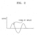
sensing gimbals 18 is set higher than the resonant frequency ω a of oscillatinggimbals 12 during the designing process to maximize sensitivity, thereby rendering a relatively small difference between the frequencies ωa -ω s . - Accordingly, as shown in FIG. 2, unnecessary signals are detected when an external shock is applied to the
microgyroscope 10. -
US 5 604 312 discloses a rate-of-rotation sensor using an oscillatory mass, and having a deflectable acceleration sensor comprising a deflectable mass associated with an acceleration sensor. - According to a first aspect of the invention, there is provided a microgyroscope comprising an oscillating mass floating over a wafer to oscillate in a first direction, a driving electrode for oscillating the oscillating mass; a sensing mass oscillating together with the oscillating mass and concurrently moving in a second direction, wherein the second direction is perpendicular to the first direction; and a sensing electrode for sensing a motion of the sensing mass with respect to the sensing electrode, wherein the microgyroscope further comprises a sensing electrode supporting portion for movably securing the sensing electrode so that the sensing electrode can move in the second direction with the sensing mass, the microgyroscope being tunable against an external translational acceleration.
- The invention thus provides a microgyroscope not easily affected by external disturbances, which is capable of synchronizing a sensing electrode and corresponding sensing gimbals in a same direction and/or with a same resonant frequency thereby eliminating unnecessary signal output made due to an external translational acceleration caused by disturbances, such as noise, shock, and the like.
- The sensing electrode supporting portion may be formed as a sensing electrode elastic body elastically disposed between the sensing electrode and the wafer for moving the sensing electrode in the second direction.
- A resonant frequency of the sensing electrode in the second direction may either be equal to or similar to a resonant frequency of the sensing mass in the sensing direction.
- In one example:
- the oscillating mass comprises outer gimbals;
- the microgyroscope further comprises a plurality of first comb units arranged on an external side of the outer gimbals;
- the driving electrode comprises at least one driving electrode unit having a plurality of second comb units arranged between the first comb units at predetermined intervals to oscillate the outer gimbals;
- the sensing mass comprises inner gimbals movably arranged to oscillate together with the outer gimbals;
- a plurality of third comb units is arranged in the second direction in one or more divisions defined in the interior of the inner gimbals; and
- the sensing electrode comprises at least one sensing electrode unit arranged in the divisions of the inner gimbals, and having a plurality of electrode comb units that are arranged between the third comb units of the divisions at predetermined intervals.
- The sensing electrode supporting portion may be formed as a sensing electrode beam elastic body elastically disposed between the sensing electrode unit and the wafer for oscillating the sensing electrode unit in the second direction. The sensing electrode beam elastic body may include an anchor secured on the wafer and extending upwards, and an elastic horizontal beam elastically disposed to connect both sides of the anchor with the sensing electrode unit.
- A resonant frequency of the sensing electrode in the sensing direction may be either equal to or similar to a resonant frequency of the inner gimbals in the second direction.
- Each of the first, the second and the third comb units may include a plurality of combs.
- The interior of the inner gimbals may be defined as a single, or a plurality of divisions where a plurality of third comb units are respectively arranged in both sides thereof, and the sensing electrode unit may include one, or a plurality of sensing electrodes arranged respectively in the single or plurality of divisions of the interior of the inner gimbals, and has a plurality of electrode comb units arranged between the third comb units at predetermined intervals.
- The above and other features and advantages of the present invention will become more apparent to those of ordinary skill in the art by describing in detail preferred embodiments thereof with reference to the attached drawings in which:
- FIG. 1 illustrates a diagram of a conventional microgyroscope;
- FIG. 2 is a graph illustrating a signal sensed when an external shock is applied to the microgyroscope of FIG. 1;
- FIG. 3 illustrates a diagram of a microgyroscope according to an embodiment of the present invention;
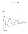
- FIG. 4A illustrates a schematic view of a 1-degree-of-freedom system for explaining a principal of a microgyroscope according to an embodiment of the present invention, and FIGS. 4B and 4C are graphs illustrating a unit shock and a response characteristic thereof of the 1-degree-of-freedom system;
- FIG. 5 illustrates a plan view of a microgyroscope according to a preferred embodiment of the present invention;
- FIG. 6 illustrates a plan view of a microgyroscope according to another preferred embodiment of the present invention; and
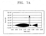
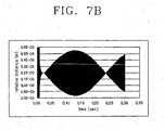
- FIGS. 7A-7E are graphs illustrating the calculated results of the relation between time and the relative displacement of first and second sensing electrodes with respect to sensing gimbals in accordance with resonant frequencies f thereof in the microgyroscope of FIG. 6 and the relation between time and relative displacement of first and second stationary electrodes with respect to sensing gimbals in accordance with resonant frequencies f thereof in the conventional microgyroscope, when an acceleration impulse of 1 G is applied for 0.01 sec.
- The present invention will now be described more fully hereinafter with reference to the accompanying drawings, in which preferred embodiments of the invention are shown. The invention may, however, be embodied in different forms and should not be construed as limited to the embodiments set forth herein. Rather, these embodiments are provided so that this disclosure will be thorough and complete, and will fully convey the scope of the invention to those skilled in the art. Like numbers refer to like elements throughout.
- FIG. 3 schematically shows a
microgyroscope 100 according to an embodiment of the present invention. - The
microgyroscope 100 according to an embodiment of the present invention is provided with oscillatinggimbals 112 defining an oscillating mass Ma floating over awafer 111 to oscillate at a resonant frequency fa in a horizontal direction, i.e., in the X-axis direction, a drivingelectrode 116 secured on thewafer 111 and having drivingcombs 117 arranged between oscillatingcombs 114 of the oscillatinggimbals 112 at predetermined intervals, sensinggimbals 118 defining a sensing mass Ms arranged to oscillate at a resonant frequency fs in a vertical direction, i.e., in the Y-axis direction, when applied with an angular velocity Ω during oscillation together with the oscillatinggimbals 112, asensing electrode 122 movably secured on thewafer 111 and havingelectrode combs 121 arranged between sensingcombs 120 of thesensing gimbals 118 at predetermined intervals, and a sensingelectrode supporting portion 128 for movably securing thesensing electrode 122 with respect to thewafer 111 so that, with the application of an external shock, thesensing electrode 122 can move in the same direction as the sensing direction of thesensing gimbals 118, i.e., move in the Y-axis direction. - The oscillating
gimbals 112 are oscillated in the X-axis direction by an oscillating directionelastic body 113 elastically disposed between the oscillatinggimbals 112 and thewafer 111. Theelastic body 113 is provided with a predetermined damping force, or adamper 115. Thesensing gimbals 118 are oscillated in the X-axis direction together with the oscillatinggimbals 112, and oscillated in a sensing direction, i.e., in the Y-axis direction, with the application of rotational force rotating at a predetermined angular velocity Ω. - Although FIG. 3 shows the
oscillating gimbals 112 having drivingcombs 117 formed on one side, and asingle driving electrode 116 being formed to correspond to the oscillatingcombs 114 by way of one example, it will be understood that theoscillating combs 114 may be additionally formed on the other side of the oscillatinggimbals 112 and the drivingelectrode 116 may have positive andnegative driving combs 117 symmetrically arranged to correspond to theoscillating combs 114. - In addition, although FIG. 3 depicts the
sensing electrode 122 having one polarity, a pair of positive and negative electrodes may also be arranged parallel to the Y-axis direction, for the purpose of reducing sensing noise and improving sensing accuracy. In this case, since the electric capacitance between the electrode combs 121 of the positive and negative sensing electrodes and thesensing comb 120 are opposite, if an external shock is applied, displacement of thesensing gimbals 118 in the Y-axis direction can be sensed by calculating a difference of capacitance generated from the positive andnegative sensing electrodes 122. - The sensing
electrode supporting portion 128 that movably secures thesensing electrode 122 to move in the Y-axis direction, is provided with a sensing electrodeelastic body 124 elastically disposed between thesensing electrode 122 and thewafer 111. The sensing electrodeelastic body 124 is provided with a predetermined damping force, or adamper 125. - A resonant frequency of the
sensing electrode 122 in a sensing direction may be equal or similar to the resonant frequency of theoscillating gimbals 118, i.e., the sensing mass. Preferably, the resonant frequency of thesensing electrode 122 in a sensing direction equals the resonant frequency of theoscillating gimbals 118 in the sensing direction. - The reason for this preferred condition will now be described. Assuming that there is no input of an angular velocity Ω externally input to the
microgyroscope 100 of FIG. 3, but there is only the input of an impulse, since theoscillating gimbals 112 are quite rigid in the Y-axis direction, the Y-axis direction property of the impulse causes the movableoscillating electrode 122 and thesensing gimbals 118 to displace in the Y-axis direction by the sensing electrodeelastic body 124 and a sensing directionelastic body 119, which is elastically disposed between the sensinggimbals 118 and theoscillating gimbals 112. The sensing directionelastic body 119 is provided with a predetermined damping force, or adamper 123. - The response characteristic of the
sensing electrode 122 and thesensing gimbals 118 by the application of the Y-axis direction impulse approximates the response characteristic of a 1-degree-of-freedom system having a mass M, spring constant k, and a damping coefficient c, as shown in FIG. 4A. - The response characteristic of the 1-degree-of-freedom system being applied with a unit impulse as shown in FIG. 4B is as follows:

where,
- As understood from equation (4), with the application of an impulse, the response characteristic of the 1-degree-of-freedom system is expressed as the resonant frequency of the mass M as shown in FIG. 4C.
- Since the response characteristic of the
sensing electrode 122 and thesensing gimbals 118 due to the Y-axis direction impulse is expressed as the resonant frequency, if the resonant frequency of thesensing electrode 122 in the sensing direction equals the resonant frequency of thesensing gimbals 118 in the sensing direction, the relative position of thesensing electrode 122 and thesensing gimbals 118 remains constant even when a Y-axis direction impulse is applied thereto. - More specifically, it is assumed that a first undamped 1-degree-of-freedom system with a mass M1 and a spring constant k1 , and a second undamped 1-degree-of-freedom system with a mass M2 and a spring constant k2 have the same resonant frequency W1 and W2 , respectively, Thus, k 1/M 1 = k 2/M 2 and an initial displacement is zero (0). Accordingly, displacement of the first and the second systems by time (t) is obtained as follows:

where υ0 is initial velocity. - Accordingly, if the initial velocity υ0 due to the external impulse applied to the first and the second systems is equal in each system, the response characteristic of the first and the second systems is similarly identical.
- For example, assuming that the mass M1 of the first system is applied with the impulse G, with velocity υ is 0 at time t=0-, and that the time immediately after the application of impulse is t=0, the following equation is obtained:

- Accordingly, the initial velocity (υ1(t = 0)) of the mass M1 is

- Assuming that the mass M2 of the second system is applied with a different impulse from the mass M1 , but with the same acceleration, the acceleration a to the mass M1 , i.e., the acceleration α with respect to the mass M2 , is, by the relation of

- Accordingly, the following equation is obtained with respect to the mass M2 .

- Accordingly, the initial velocity υ2 (t = 0) of the mass M2 is,

- With the same initial velocity of the masses M1, M2 of the first and the second systems, and the same resonant frequency, there is provided the same response characteristic to the external impulse.
- In the case of
microgyroscope 100, thesensing gimbals 118 and thesensing electrode 122 with different shapes and volumes would have different damping coefficients c in an atmospheric environment. Once being packed in a vacuum, however, the damping coefficients c of thesensing gimbals 118 and thesensing electrode 122 are only influenced by the damping property of the material forming the same. As a result, the damping coefficients c of thesensing gimbals 118 and thesensing electrode 122 are almost equal to each other. - As described above, by using the
movable sensing electrode 122 which is movably secured in thewafer 111, and the fact that thesensing gimbals 118 and thesensing electrode 122 have the same displacement with respect to the external impulse, detection of a signal due to the external impulse can be prevented. - The operation of the
microgyroscope 100 constructed as above according to the present invention will be described below. - First, with the application of AC power to the driving
electrode 116, theoscillating gimbals 112 and thesensing gimbals 118 are oscillated in the X-axis direction with resonant frequency fa due to the electrostatic force between the oscillating and drivingcombs elastic body 113. - At this time, as the
microgyroscope 100 is rotated by the external force with the angular velocity Ω, theoscillating gimbals 112 and thesensing gimbals 118 are subject to the Coriolis force in the Y-axis direction, and accordingly, thesensing gimbals 118 are oscillated by the sensing directionelastic body 119 in the Y-axis direction. - With the displacement of the
sensing gimbals 118 in the Y-axis direction by several tens of nanometers to several nanometers, the sensing combs 120 of thesensing gimbals 118 are displaced relative to the electrode combs 121 of thesensing electrodes 122. As a result, an electric capacitance between the sensing combs and the electrode combs 120 and 121, respectively, varies. Accordingly, the variation of a voltage signal is detected as the angular velocity by a circuit (not shown). - Assuming that the impulse is imposed externally, since the
oscillating gimbals 112 have relatively great rigidity in the Y-axis direction, the Y-axis component of the impulse causes only thesensing electrode 122 and thesensing gimbals 118 to displace. - However, since the response characteristic of the
sensing electrode 122 and thesensing gimbals 118 to the Y-axis component of the impulse may be expressed as the identical resonant frequency due to the sensing electrodeelastic body 124, displacement of thesensing electrode 122 and thesensing gimbals 118 is identical with respect to each other even with the application of the Y-axis component of the impulse. Accordingly, the electric capacitance between the sensing and electrode combs 120 and 121, respectively, of thesensing electrode 122, and thesensing gimbals 118 is free from the influence of the Y-axis component of the impulse. Thus, sensing of the signal due to the Y-axis component of the impulse is prevented. - Referring to FIG. 5, a microgyroscope 100' according to a first embodiment of the present invention is illustrated.
- The microgyroscope 100' according to this first preferred embodiment of the present invention is provided with elongated oscillating gimbals 112', which are formed to float over a wafer 111', to oscillate in a horizontal direction, i.e., in the X-axis direction, a first comb 114' including a plurality of first combs 114a, 114b disposed on upper and lower sides (as shown in FIG. 5) of the oscillating gimbals 112' at predetermined intervals, a driving electrode unit 116' including four driving electrode units 116a, 116b, 116c, 116d having a plurality of second combs 117a, 117b, 117c, 117d arranged between the first combs 114a, 114b at predetermined intervals to oscillate the oscillating gimbals 112' with the application of a power supply, sensing gimbals 118' arranged in the oscillating gimbals 112' to oscillate together with the oscillating gimbals 112' in a sensing direction, i.e., in a vertical, or Y-axis, direction, a plurality of third combs 120a, 120b arranged on the upper and lower sides (as shown in FIG. 5) inside of the sensing gimbals 118', a sensing electrode unit 122' having a plurality of electrode comb units 121a, 121b arranged between the third combs 120a, 120b at predetermined intervals, and a sensing electrode supporting portion 128' for movably securing the sensing electrode unit 122' with respect to the wafer 111' so that the sensing electrode unit 122' is oscillated in the same direction as the sensing direction of the sensing gimbals 118', i.e., in the Y-axis direction.
- The oscillating gimbals 112' are oscillated in the X-axis direction by an oscillating direction elastic securing portion 113' of a predetermined damping force elastically disposed between the oscillating gimbals 112' and the wafer 111'. The oscillating direction elastic securing portion 113' includes four oscillating direction beam
elastic bodies - On the left and right outer sides of the oscillating gimbals 112' (as shown in FIG. 5) is formed a
comb sensor 126 that senses the vibration of the sensing gimbals 118' in the X-axis direction. Thecomb sensor 126 includes twocomb sensing units fifth combs 126a', 126b' oppositely formed with respect to thefourth combs comb sensor 126 during the oscillation of thefirst combs electrode units - The driving
electrode units comb sensing units electrode units electrode units - The sensing gimbals 118' are oscillated in the Y-axis direction by a sensing direction elastic securing portion 119' elastically disposed between the sensing gimbals 118' and the oscillating gimbals 112'. The sensing direction elastic securing portion 119' includes two sensing direction beam
elastic bodies - The sensing electrode unit 122' is constructed of either a positive, or a negative, sensing electrode connected to a positive, or a negative, electrode supporting portion (not shown), and with the application of external impulse, is capable of sensing the displacement of the sensing gimbals 118' in the Y-axis direction by calculating the difference of an electric capacitance between the electrode combs 121a, 121b of the positive, or the negative, sensing electrode 122' and the
third combs - The sensing electrode supporting portion 128' is formed as a sensing electrode beam elastic body that has an anchor or a vertical column 127' secured on the upper surface of the wafer 111' and extended upwardly, and an elastic horizontal beam 124' elastically disposed to connect the both upper sides of the anchor 127' and the sensing electrode unit 122'.
- It is designed such that the sensing direction resonant frequency of the sensing electrode unit 122' supported by the sensing electrode beam elastic body 128' is identical to the sensing direction resonant frequency of the sensing gimbals 118' supported by the sensing direction beam
elastic bodies - Accordingly, each of the sensing electrode unit 122' and the sensing gimbals 118' under the Y-axis impulse is displaced as much as the other is, and as a result, the electric capacitance between the
electrode comb units 121a, 121b of the sensing electrode unit 122' and thethird combs - The operation of the microgyroscope 100' constructed as above is almost identical to that of the
microgyroscope 100 of FIG. 3 in principle. Accordingly, a description thereof will be omitted. - Referring to FIG. 6, a
microgyroscope 100" according to a second embodiment of the present invention is illustrated. - The
microgyroscope 100" according to this embodiment is similar to the first preferred embodiment of the present invention, as shown in FIG. 5, except that thesensing gimbals 118" are divided into twodivisions sensing electrode unit 122" is arranged in the twodivisions - The
sensing gimbals 118" are provided with a plurality ofthird combs 120a', 120b'; 120c, 120d arranged respectively on both upper and lower sides (as shown in FIG. 6) of therespective divisions - The
sensing electrode unit 122" includes first andsecond sensing electrodes divisions - The first and the
second sensing electrodes electrode comb units 121a', 121b'; 121c, 121d arranged between the respectivethird combs 120a', 120b'; 120c, 120d of thedivisions third combs 120a', 120b'; 120c, 120d at predetermined intervals. - Further, the first and the
second sensing electrodes wafer 111" by the first and the second sensingelectrode supporting portions 128", 128"', each being constructed as a sensing electrode beam elastic body that has avertical column 127", 127''', and an elastichorizontal beam 124", 124''', so as to move in the Y-axis direction. - Further, in order to reduce sensing noise and thus increase the sensitivity, the first and the
second sensing electrodes sensing gimbals 118" in the Y-axis direction is sensed. - FIGS. 7B, 7C and 7D illustrate the calculated results of the relation between time and the relative distance of the displacement of the first and the
second sensing electrodes sensing gimbals 118" according to the resonant frequencies f of thesensing gimbals 118", theelectrode comb units 121a', 121b' of thefirst sensing electrode 122a and theelectrode comb units second sensing electrode 122b, when an acceleration impulse of 1 G is applied for 0.01 sec as shown in FIG. 7A. - The calculation is based on the sensing gimbals 118'' having a weight of 3.4E-8 kg, a stiffness of 14.50 N/m, and a damping coefficient of 6.4E-6 N-sec/m, and first and the
second sensing electrodes - FIG. 7B shows the relative distance of the
sensing gimbals 118 and thefirst sensing electrode 122a when the resonant frequency f of thesensing gimbals 118", the resonant frequency f of theelectrode comb units 121a', 121b' of thefirst sensing electrode 122a and the resonant frequency f of theelectrode comb units second sensing electrode 122b are equal to each other at 10.32 kHz, which indicates that there is no response to the external acceleration impulse of 1 G. - FIGS. 7C and 7D illustrate the results when the resonant frequencies f of the sensing gimbals 118'', the
electrode comb units 121a', 121b' of thefirst sensing electrode 122a, and theelectrode comb units second sensing electrode 122b are respectively sensed as 10.32 kHz, 10.53 kHz, and 10.37 kHz, and 10.32 kHz, 10.59 kHz, and 10.59 kHz due to fabrication errors. As shown in FIGS. 7C and 7D, although there is an abnormal signal being sensed, it is negligible as compared to the abnormal signals of FIG. 7E that are sensed to the first and thesecond sensing electrodes wafer 111 " as in the prior art case when impulse of 1 G is applied for 0.01 sec. - Since the operation of the
microgyroscope 100" according to the second preferred embodiment of the present invention is almost identical to that of the microgyroscope of FIG. 3 in principle, a description thereof will be omitted. - As described above, by arranging the sensing gimbals and the sensing electrodes opposite to the sensing gimbals to move in the same direction and/or with the same resonant frequency in a sensing direction, the microgyroscope according to the present invention does not sense unnecessary signals generated due to an external translational acceleration caused by external disturbances, such as noise and impulse.
- Preferred embodiments of the present invention have been disclosed herein and, although specific terms are employed, they are used and are to be interpreted in a generic and descriptive sense only and not for purpose of limitation. Accordingly, it will be understood by those of ordinary skill in the art that various changes in form and details may be made without departing from the scope of the present invention as set forth in the following claims.
Claims (10)
- A microgyroscope comprising:an oscillating mass (112) floating over a wafer to oscillate in a first direction;a driving electrode (116) for oscillating the oscillating mass;a sensing mass (118) oscillating together with the oscillating mass and concurrently moving in a second direction, wherein the second direction is perpendicular to the first direction; anda sensing electrode (122) for sensing a motion of the sensing mass (118) with respect to the sensing electrode (122), characterized in that the microgyroscope further comprises:a sensing electrode supporting portion (125,128) for movably securing the sensing electrode (122) so that the sensing electrode can move in the second direction with the sensing mass (118), the micro gyroscope being tunable against an external translational acceleration.
- The microgyroscope as claimed in claim 1, wherein the sensing electrode supporting portion (125,128) comprises a sensing electrode elastic body (128) elastically disposed between the sensing electrode (122) and the wafer (111) for moving the sensing electrode in the second direction, the sensing electrode elastic body being provided with a predetermined damping force or a damper (125).
- The microgyroscope as claimed in claim 1 or 2, wherein a resonant frequency of the sensing electrode (122) in the second direction is either equal to or similar to a resonant frequency of the sensing mass (118) in the second direction.
- A microgyroscope as claimed in claim 1, wherein:the oscillating mass (112) comprises outer gimbals;the microgyroscope further comprises a plurality of first comb units (114) arranged on an external side of the outer gimbals (112);the driving electrode (116) comprises at least one driving electrode unit having a plurality of second comb units (117) arranged between the first comb units at predetermined intervals to oscillate the outer gimbals (112);the sensing mass (118) comprises inner gimbals (118) movably arranged to oscillate together with the outer gimbals (112);a plurality of third comb units (120) is arranged in the second direction in one or more divisions defined in the interior of the inner gimbals (118); andthe sensing electrode (122) comprises at least one sensing electrode unit arranged in the divisions of the inner gimbals (118), and having a plurality of electrode comb units (121) that are arranged between the third comb units (120) of the divisions at predetermined intervals.
- The microgyroscope as claimed in claim 4, wherein the sensing electrode supporting portion comprises a sensing electrode beam elastic body elastically disposed between the sensing electrode unit and the wafer for oscillating the sensing electrode unit in the second direction.
- The microgyroscope as claimed in claim 5, wherein the sensing electrode beam elastic body comprises:an anchor secured on the wafer and extending upwards; andan elastic horizontal beam elastically disposed to connect both sides of the anchor with the sensing electrode unit.
- The microgyroscope as claimed in any one of claims 4 to 6, wherein a resonant frequency of the sensing electrode (122) in the sensing direction is either equal to or similar to a resonant frequency of the inner gimbals (118) in the second direction.
- The microgyroscope as claimed in any one of claims 4 to 7, wherein the first, the second and the third comb units each comprise a plurality of combs.
- The microgyroscope as claimed in any one of claims 4 to 8, wherein the interior of the inner gimbals (118) is defined as a single division where a plurality of third comb units are respectively arranged in both sides thereof, and
the sensing electrode unit comprises one sensing electrode that is arranged in the single division of the interior of the inner gimbals, and has a plurality of electrode comb units arranged between the third comb units at predetermined intervals. - The microgyroscope as claimed in any one of claims 4 to 8, wherein the interior of the inner gimbals is defined as more than two divisions where a plurality of third comb units are respectively arranged in both sides thereof, and
the sensing electrode unit comprises a plurality of sensing electrodes that are respectively arranged in the divisions of the interior of the inner gimbals, and has a plurality of electrode comb units arranged between the third comb units at predetermined intervals.
Applications Claiming Priority (2)
| Application Number | Priority Date | Filing Date | Title |
|---|---|---|---|
| KR10-2002-0062301A KR100470590B1 (en) | 2002-10-12 | 2002-10-12 | Microgyroscopes with suppressed translational acceleration sensing |
| KR2002062301 | 2002-10-12 |
Publications (3)
| Publication Number | Publication Date |
|---|---|
| EP1408302A2 EP1408302A2 (en) | 2004-04-14 |
| EP1408302A3 EP1408302A3 (en) | 2005-10-12 |
| EP1408302B1 true EP1408302B1 (en) | 2007-11-14 |
Family
ID=36086259
Family Applications (1)
| Application Number | Title | Priority Date | Filing Date |
|---|---|---|---|
| EP03256281A Expired - Lifetime EP1408302B1 (en) | 2002-10-12 | 2003-10-06 | Microgyroscope tunable for translational acceleration |
Country Status (7)
| Country | Link |
|---|---|
| US (1) | US6860150B2 (en) |
| EP (1) | EP1408302B1 (en) |
| JP (1) | JP2004132988A (en) |
| KR (1) | KR100470590B1 (en) |
| CN (1) | CN1246668C (en) |
| DE (1) | DE60317436T2 (en) |
| TW (1) | TWI230781B (en) |
Families Citing this family (33)
| Publication number | Priority date | Publication date | Assignee | Title |
|---|---|---|---|---|
| JP3937334B2 (en) * | 2003-03-27 | 2007-06-27 | 株式会社デンソー | Abnormality detection device for vibration type angular velocity sensor, abnormality detection method, abnormality detection program, and vehicle control system |
| US6880400B1 (en) * | 2003-05-23 | 2005-04-19 | The United States Of America As Represented By The Secretary Of The Navy | Phase synchronized array of non-identical oscillators using coupling network |
| US20050066728A1 (en) * | 2003-09-25 | 2005-03-31 | Kionix, Inc. | Z-axis angular rate micro electro-mechanical systems (MEMS) sensor |
| KR100616641B1 (en) * | 2004-12-03 | 2006-08-28 | 삼성전기주식회사 | Tuning Fork Vibratory MEMS Gyroscope |
| US7621183B2 (en) * | 2005-11-18 | 2009-11-24 | Invensense Inc. | X-Y axis dual-mass tuning fork gyroscope with vertically integrated electronics and wafer-scale hermetic packaging |
| US7796872B2 (en) * | 2007-01-05 | 2010-09-14 | Invensense, Inc. | Method and apparatus for producing a sharp image from a handheld device containing a gyroscope |
| US7934423B2 (en) | 2007-12-10 | 2011-05-03 | Invensense, Inc. | Vertically integrated 3-axis MEMS angular accelerometer with integrated electronics |
| US8047075B2 (en) | 2007-06-21 | 2011-11-01 | Invensense, Inc. | Vertically integrated 3-axis MEMS accelerometer with electronics |
| US8141424B2 (en) | 2008-09-12 | 2012-03-27 | Invensense, Inc. | Low inertia frame for detecting coriolis acceleration |
| US8020441B2 (en) | 2008-02-05 | 2011-09-20 | Invensense, Inc. | Dual mode sensing for vibratory gyroscope |
| US8462109B2 (en) | 2007-01-05 | 2013-06-11 | Invensense, Inc. | Controlling and accessing content using motion processing on mobile devices |
| US8508039B1 (en) | 2008-05-08 | 2013-08-13 | Invensense, Inc. | Wafer scale chip scale packaging of vertically integrated MEMS sensors with electronics |
| US8952832B2 (en) | 2008-01-18 | 2015-02-10 | Invensense, Inc. | Interfacing application programs and motion sensors of a device |
| US20090262074A1 (en) * | 2007-01-05 | 2009-10-22 | Invensense Inc. | Controlling and accessing content using motion processing on mobile devices |
| US8250921B2 (en) | 2007-07-06 | 2012-08-28 | Invensense, Inc. | Integrated motion processing unit (MPU) with MEMS inertial sensing and embedded digital electronics |
| CN101563582B (en) * | 2007-09-19 | 2011-08-24 | 株式会社村田制作所 | Composite sensor and acceleration sensor |
| US7677099B2 (en) * | 2007-11-05 | 2010-03-16 | Invensense Inc. | Integrated microelectromechanical systems (MEMS) vibrating mass Z-axis rate sensor |
| US7755367B2 (en) | 2008-06-02 | 2010-07-13 | Infineon Technologies, Ag | Silicon MEMS resonators |
| JP5228675B2 (en) * | 2008-07-29 | 2013-07-03 | 富士通株式会社 | Angular velocity sensor and electronic device |
| DE102008057281A1 (en) * | 2008-11-14 | 2010-05-20 | Northrop Grumman Litef Gmbh | Simulation method for the operating behavior of a Coriolis gyro |
| US8534127B2 (en) | 2009-09-11 | 2013-09-17 | Invensense, Inc. | Extension-mode angular velocity sensor |
| US9097524B2 (en) | 2009-09-11 | 2015-08-04 | Invensense, Inc. | MEMS device with improved spring system |
| CN102175236B (en) * | 2011-02-14 | 2012-12-12 | 厦门大学 | Micro gyroscope capable of regulating and reducing quadrature errors |
| ITTO20110688A1 (en) * | 2011-07-28 | 2013-01-29 | St Microelectronics Srl | MICROELETTROMECHANICAL GYROSCOPE WITH SELF-CALIBRATION FUNCTION AND METHOD OF CALIBRATION OF A MICROELECTRANOMANICAL GYROSCOPE |
| US8875578B2 (en) * | 2011-10-26 | 2014-11-04 | Silicon Laboratories Inc. | Electronic damper circuit for MEMS sensors and resonators |
| FI125238B (en) * | 2012-06-29 | 2015-07-31 | Murata Manufacturing Co | Improved oscillating gyroscope |
| KR101318421B1 (en) | 2013-04-08 | 2013-10-16 | 한국생산기술연구원 | Carboxymethyl cellulose foam for hemostatic and wound healing, and method of producing the same |
| CN110514190B (en) | 2015-04-24 | 2023-07-14 | 意法半导体股份有限公司 | Microelectromechanical gyroscope for sensing angular rate and method of sensing angular rate |
| KR101679592B1 (en) * | 2015-05-12 | 2016-11-25 | 주식회사 신성씨앤티 | Symmetrical z-axis MEMS gyroscopes |
| ITUA20162172A1 (en) * | 2016-03-31 | 2017-10-01 | St Microelectronics Srl | ACCELEROMETRIC SENSOR MADE IN MEMS TECHNOLOGY WITH HIGH ACCURACY AND REDUCED SENSITIVITY TOWARDS TEMPERATURE AND AGING |
| IT201900017546A1 (en) | 2019-09-30 | 2021-03-30 | St Microelectronics Srl | WATER RESISTANT MEMS BUTTON DEVICE, INPUT DEVICE INCLUDING MEMS BUTTON DEVICE AND ELECTRONIC DEVICE |
| IT202100024644A1 (en) | 2021-09-27 | 2023-03-27 | St Microelectronics Srl | CONTROL CIRCUIT OF A MEMS GYRO, MEMS GYRO AND CONTROL METHOD |
| CN115342794B (en) * | 2022-07-07 | 2026-04-14 | 北京理工大学 | MEMS gyroscope based on dithering structure and zero offset suppression method thereof |
Family Cites Families (7)
| Publication number | Priority date | Publication date | Assignee | Title |
|---|---|---|---|---|
| US5408877A (en) * | 1992-03-16 | 1995-04-25 | The Charles Stark Draper Laboratory, Inc. | Micromechanical gyroscopic transducer with improved drive and sense capabilities |
| DE4442033C2 (en) * | 1994-11-25 | 1997-12-18 | Bosch Gmbh Robert | Yaw rate sensor |
| KR100211025B1 (en) * | 1996-12-20 | 1999-07-15 | 정선종 | Vibration Micro Gyroscope |
| KR100231715B1 (en) * | 1997-11-25 | 1999-11-15 | 정선종 | Planar Vibration Micro Gyroscope |
| KR100493149B1 (en) * | 1999-01-15 | 2005-06-02 | 삼성전자주식회사 | Symmetrical Z-axis gyroscope and fabricating method thereof |
| KR100363786B1 (en) * | 1999-05-13 | 2002-12-11 | 삼성전기주식회사 | Microgyrocrope |
| KR100363785B1 (en) * | 1999-06-04 | 2002-12-11 | 삼성전기주식회사 | Microgyrocrope |
-
2002
- 2002-10-12 KR KR10-2002-0062301A patent/KR100470590B1/en not_active Expired - Fee Related
-
2003
- 2003-08-07 US US10/635,471 patent/US6860150B2/en not_active Expired - Lifetime
- 2003-10-06 DE DE60317436T patent/DE60317436T2/en not_active Expired - Lifetime
- 2003-10-06 EP EP03256281A patent/EP1408302B1/en not_active Expired - Lifetime
- 2003-10-10 CN CNB2003101010178A patent/CN1246668C/en not_active Expired - Fee Related
- 2003-10-10 JP JP2003352772A patent/JP2004132988A/en active Pending
- 2003-10-13 TW TW092128274A patent/TWI230781B/en not_active IP Right Cessation
Also Published As
| Publication number | Publication date |
|---|---|
| TW200416394A (en) | 2004-09-01 |
| EP1408302A3 (en) | 2005-10-12 |
| KR20040035946A (en) | 2004-04-30 |
| US20040069062A1 (en) | 2004-04-15 |
| JP2004132988A (en) | 2004-04-30 |
| CN1246668C (en) | 2006-03-22 |
| TWI230781B (en) | 2005-04-11 |
| DE60317436T2 (en) | 2008-04-17 |
| EP1408302A2 (en) | 2004-04-14 |
| US6860150B2 (en) | 2005-03-01 |
| CN1497240A (en) | 2004-05-19 |
| KR100470590B1 (en) | 2005-03-08 |
| DE60317436D1 (en) | 2007-12-27 |
Similar Documents
| Publication | Publication Date | Title |
|---|---|---|
| EP1408302A2 (en) | Microgyroscope tunable for translational acceleration | |
| EP2404139B1 (en) | Vibrating micro-mechanical sensor of angular velocity | |
| US6742390B2 (en) | Angular velocity sensor | |
| US7191653B2 (en) | Tuning fork vibratory MEMS gyroscope | |
| US8176779B2 (en) | Vibrating micro-mechanical sensor of angular velocity | |
| EP2327959B1 (en) | Micromachined gyroscope | |
| EP3428576B1 (en) | Angular rate sensor with in-phase motion suppression structure | |
| US8342023B2 (en) | Coriolis gyro | |
| US6327907B1 (en) | Microgyroscope having asymmetric comb sensors | |
| EP2527789A1 (en) | Oscillating micro-mechanical sensor of angular velocity | |
| US9219169B2 (en) | Angular velocity sensor | |
| JP2008514968A (en) | Rotational speed sensor | |
| CN104136886A (en) | Multiaxial micro-electronic inertial sensor | |
| AU2007336930A1 (en) | Vibratory gyroscope with parasitic mode damping | |
| US20030084722A1 (en) | Vibration-type micro-gyroscope | |
| US6301963B1 (en) | Microgyroscope having inner and outer mass parts | |
| US6718825B1 (en) | Methods and systems for reducing stick-down within MEMS structures | |
| Soderkvist | Micromachined vibrating gyroscopes | |
| KR100319920B1 (en) | Laterally driving gimbal type gyroscope having unbalanced inner torsional gimbal | |
| Hayworth et al. | Electrostatic spring softening in redundant degree of freedom resonators | |
| KR100491590B1 (en) | Microgyroscope |
Legal Events
| Date | Code | Title | Description |
|---|---|---|---|
| PUAI | Public reference made under article 153(3) epc to a published international application that has entered the european phase |
Free format text: ORIGINAL CODE: 0009012 |
|
| AK | Designated contracting states |
Kind code of ref document: A2 Designated state(s): AT BE BG CH CY CZ DE DK EE ES FI FR GB GR HU IE IT LI LU MC NL PT RO SE SI SK TR |
|
| AX | Request for extension of the european patent |
Extension state: AL LT LV MK |
|
| RAP1 | Party data changed (applicant data changed or rights of an application transferred) |
Owner name: SAMSUNG ELECTRO-MECHANICS CO. LTD. |
|
| PUAL | Search report despatched |
Free format text: ORIGINAL CODE: 0009013 |
|
| AK | Designated contracting states |
Kind code of ref document: A3 Designated state(s): AT BE BG CH CY CZ DE DK EE ES FI FR GB GR HU IE IT LI LU MC NL PT RO SE SI SK TR |
|
| AX | Request for extension of the european patent |
Extension state: AL LT LV MK |
|
| 17P | Request for examination filed |
Effective date: 20051214 |
|
| AKX | Designation fees paid |
Designated state(s): DE FR GB IT |
|
| GRAP | Despatch of communication of intention to grant a patent |
Free format text: ORIGINAL CODE: EPIDOSNIGR1 |
|
| GRAS | Grant fee paid |
Free format text: ORIGINAL CODE: EPIDOSNIGR3 |
|
| GRAA | (expected) grant |
Free format text: ORIGINAL CODE: 0009210 |
|
| AK | Designated contracting states |
Kind code of ref document: B1 Designated state(s): DE FR GB IT |
|
| REG | Reference to a national code |
Ref country code: GB Ref legal event code: FG4D |
|
| REF | Corresponds to: |
Ref document number: 60317436 Country of ref document: DE Date of ref document: 20071227 Kind code of ref document: P |
|
| ET | Fr: translation filed | ||
| PLBE | No opposition filed within time limit |
Free format text: ORIGINAL CODE: 0009261 |
|
| STAA | Information on the status of an ep patent application or granted ep patent |
Free format text: STATUS: NO OPPOSITION FILED WITHIN TIME LIMIT |
|
| 26N | No opposition filed |
Effective date: 20080815 |
|
| REG | Reference to a national code |
Ref country code: FR Ref legal event code: PLFP Year of fee payment: 13 |
|
| REG | Reference to a national code |
Ref country code: FR Ref legal event code: PLFP Year of fee payment: 14 |
|
| REG | Reference to a national code |
Ref country code: FR Ref legal event code: PLFP Year of fee payment: 15 |
|
| REG | Reference to a national code |
Ref country code: FR Ref legal event code: PLFP Year of fee payment: 16 |
|
| PGFP | Annual fee paid to national office [announced via postgrant information from national office to epo] |
Ref country code: FR Payment date: 20190906 Year of fee payment: 17 |
|
| PGFP | Annual fee paid to national office [announced via postgrant information from national office to epo] |
Ref country code: GB Payment date: 20190909 Year of fee payment: 17 |
|
| PGFP | Annual fee paid to national office [announced via postgrant information from national office to epo] |
Ref country code: DE Payment date: 20190905 Year of fee payment: 17 |
|
| PGFP | Annual fee paid to national office [announced via postgrant information from national office to epo] |
Ref country code: IT Payment date: 20191015 Year of fee payment: 17 |
|
| REG | Reference to a national code |
Ref country code: DE Ref legal event code: R119 Ref document number: 60317436 Country of ref document: DE |
|
| GBPC | Gb: european patent ceased through non-payment of renewal fee |
Effective date: 20201006 |
|
| PG25 | Lapsed in a contracting state [announced via postgrant information from national office to epo] |
Ref country code: DE Free format text: LAPSE BECAUSE OF NON-PAYMENT OF DUE FEES Effective date: 20210501 Ref country code: FR Free format text: LAPSE BECAUSE OF NON-PAYMENT OF DUE FEES Effective date: 20201031 |
|
| PG25 | Lapsed in a contracting state [announced via postgrant information from national office to epo] |
Ref country code: GB Free format text: LAPSE BECAUSE OF NON-PAYMENT OF DUE FEES Effective date: 20201006 |
|
| PG25 | Lapsed in a contracting state [announced via postgrant information from national office to epo] |
Ref country code: IT Free format text: LAPSE BECAUSE OF NON-PAYMENT OF DUE FEES Effective date: 20201006 |