EP1408259A1 - A method of detecting wear in a motor vehicle transmission and a transmission provided with means to detect such wear - Google Patents
A method of detecting wear in a motor vehicle transmission and a transmission provided with means to detect such wear Download PDFInfo
- Publication number
- EP1408259A1 EP1408259A1 EP20020445125 EP02445125A EP1408259A1 EP 1408259 A1 EP1408259 A1 EP 1408259A1 EP 20020445125 EP20020445125 EP 20020445125 EP 02445125 A EP02445125 A EP 02445125A EP 1408259 A1 EP1408259 A1 EP 1408259A1
- Authority
- EP
- European Patent Office
- Prior art keywords
- duty cycle
- torque
- transmission
- wear
- component
- Prior art date
- Legal status (The legal status is an assumption and is not a legal conclusion. Google has not performed a legal analysis and makes no representation as to the accuracy of the status listed.)
- Granted
Links
Images

Classifications
-
- G—PHYSICS
- G01—MEASURING; TESTING
- G01M—TESTING STATIC OR DYNAMIC BALANCE OF MACHINES OR STRUCTURES; TESTING OF STRUCTURES OR APPARATUS, NOT OTHERWISE PROVIDED FOR
- G01M13/00—Testing of machine parts
- G01M13/02—Gearings; Transmission mechanisms
- G01M13/021—Gearings
-
- F—MECHANICAL ENGINEERING; LIGHTING; HEATING; WEAPONS; BLASTING
- F16—ENGINEERING ELEMENTS AND UNITS; GENERAL MEASURES FOR PRODUCING AND MAINTAINING EFFECTIVE FUNCTIONING OF MACHINES OR INSTALLATIONS; THERMAL INSULATION IN GENERAL
- F16H—GEARING
- F16H57/00—General details of gearing
- F16H57/01—Monitoring wear or stress of gearing elements, e.g. for triggering maintenance
-
- F—MECHANICAL ENGINEERING; LIGHTING; HEATING; WEAPONS; BLASTING
- F16—ENGINEERING ELEMENTS AND UNITS; GENERAL MEASURES FOR PRODUCING AND MAINTAINING EFFECTIVE FUNCTIONING OF MACHINES OR INSTALLATIONS; THERMAL INSULATION IN GENERAL
- F16H—GEARING
- F16H57/00—General details of gearing
- F16H57/01—Monitoring wear or stress of gearing elements, e.g. for triggering maintenance
- F16H2057/012—Monitoring wear or stress of gearing elements, e.g. for triggering maintenance of gearings
-
- F—MECHANICAL ENGINEERING; LIGHTING; HEATING; WEAPONS; BLASTING
- F16—ENGINEERING ELEMENTS AND UNITS; GENERAL MEASURES FOR PRODUCING AND MAINTAINING EFFECTIVE FUNCTIONING OF MACHINES OR INSTALLATIONS; THERMAL INSULATION IN GENERAL
- F16H—GEARING
- F16H57/00—General details of gearing
- F16H57/01—Monitoring wear or stress of gearing elements, e.g. for triggering maintenance
- F16H2057/014—Monitoring wear or stress of gearing elements, e.g. for triggering maintenance of friction elements in transmissions
-
- F—MECHANICAL ENGINEERING; LIGHTING; HEATING; WEAPONS; BLASTING
- F16—ENGINEERING ELEMENTS AND UNITS; GENERAL MEASURES FOR PRODUCING AND MAINTAINING EFFECTIVE FUNCTIONING OF MACHINES OR INSTALLATIONS; THERMAL INSULATION IN GENERAL
- F16H—GEARING
- F16H61/00—Control functions within control units of change-speed- or reversing-gearings for conveying rotary motion ; Control of exclusively fluid gearing, friction gearing, gearings with endless flexible members or other particular types of gearing
- F16H61/12—Detecting malfunction or potential malfunction, e.g. fail safe ; Circumventing or fixing failures
Definitions
- the present invention relates to a method of detecting wear of at least one preselected torque transmitting component in a motor vehicle transmission comprising an electronic control unit wherein signals at least representing selected gear ratio, transmission input shaft torque and input shaft rotational speed are available in the control unit.
- the invention also relates to a motor vehicle transmission including an electronic control unit, signals at least representing selected gear ratio, transmission input shaft torque and input shaft rotational speed being available in the electronic control unit.
- Motor vehicle transmissions are normally dimensioned for that specific type of vehicle in which they are to be used and to transmit torque from the engine which the transmission is connected to over a calculated life length of the vehicle based on normal driver behaviour and driving conditions.
- "normal" driver behaviour and driving conditions usually vary depending on the type of car. For example a regular passenger car will hardly be driven as a high performance sports car and vice versa and neither one will ever be driven off-road in rough terrain.
- Off-road driving requires motor vehicles specially designed for such conditions and they have heavy duty drive lines dimensioned to last over the calculated life lengh of the vehicle even when a substantial share of driving is off-road.
- a new type of passenger car has become very popular, namely a so called sports utility vehicle (SUV).
- SUV sports utility vehicle
- Some of these are designed and have heavy duty drive lines specially dimensioned for driving off-road in rough terrain while others are designed to be driven primarily on the road and only occasionally in terrain which, however, must not be rough. Not only when a vehicle is driven off-road but also, for example, when it is driven as a tow vehicle or when a substantial share of driving is in heavy traffic with many starts and stop it is subject to severe loads.
- a general purpose of the present invention is to achieve a method to detect wear in a motor vehicle transmission of the type described by way of introduction so as to enable the use of almost the same transmission specifications for a wide range of engines and types of vehicles.
- a further purpose of the present invention is to achieve a method to detect wear which can be used to eliminate the need to overdimension transmissions for that type of SUVs which can be expected never or only occasionally to be driven off-road.
- the predetermined total duty cycle is based on a Wöhler diagram obtained from tests of said preselected torque transmitting component.
- a component is selected which is expected to be one that most likely will break down first .
- Such a component could be a gear wheel of a gear set transmitting torque with the highest gear ratio to the driving wheels of the vehicle.
- An individual total duty cycle for each such component is predermined. The accumulated measured duty cycle of each component is then compared with the individual predetermined total duty cycle related to the component in question.
- the level of wear of the preselected torque transmitting component is preferably defined as the accumulated measured duty cycle divided by said predetermined total duty cycle.
- a signal representing this duty cycle relation can be used either as an input signal to external test equipment and the wear can then be detected with regular intervals in connection with regular services of the vehicle or as an input signal to a computer in the car having a dashboard display, thereby enabling on-board detection.
- Another purpose of the present invention is to achieve a motor vehicle transmission of the type described by way of introduction provided with means to detect outstanding user situations which may decrease the life length of the transmission.
- the electronic control unit is arranged to calculate wear of a preselected torque transmitting component of the transmission by accumulating a measured duty cycle representative of revolutions and related torque transmitted by said component when running and by comparing the accumulated measured duty cycle with a predetermined total duty cycle which represents a predetermined level of wear of said component.
- the sun gear of a planetary gear set transmitting torque with the highest gear ratio is said preselected torque transmitting component.
- Fig. 1 an internal combustion engine 1 for a motor vehicle is shown, the crankshaft (not shown) of which via a torque converter (not shown) is drivingly connected to an input shaft 2 (Fig. 2) of an automatic transmission 3.
- the engine 1 is controlled by an electronic engine control unit 4 in response to signals representing various control parameters, one being requested torque, e. g. the position of an accelerator pedal 5.
- the engine control unit 4 communicates with an electronic transmission control unit 6, which is connected to a manual gear selector 7 by means of which the driver can select either automatic or manual shifting of the transmission 3.
- the control unit 6 controls shifting in response at least to vehicle speed, transmission input shaft torque and input shaft rotational speed.
- the engine control function and the transmission control function can of course be integrated in a single control unit.
- the transmission is a well known automatic transmission which has been on the market for several years. Therefore, it will only be described briefly here. It comprises three planetary gear sets, namely an input gear set 10, a reaction gear set 11 and a final drive gear set 12.
- first gear i. e. the gear having the highest gear ratio
- torque is transmitted from the input shaft 2 via the sun gear 13 of the input gear set 10 to the output shaft 14 which is connected to the planet carrier 15 of the final drive gear set 12.
- At least one critical torque transmitting component is preselected, e. g. that component of the transmission which is most likely to become seriously damaged first.
- This component could be the sun gear 13 of the input gear set 10.
- a Wöhler diagram for the selected component is established. An example of such a diagram is shown in Fig. 3 wherein T is torque and n is number of revolutions.
- the Wöhler diagram is mapped in the transmission control unit 6 to a 2D-lookup table with for example twenty samples. The table is indexed with real transmission input torque and read out number of rotations.
- a total duty cycle figure, DC tot is set. DC is defined according to: wherein w is the Wöhler exponent.
- transmission input torque T i and input speed are sampled at regular intervals, e. g. each 25 ms. Input speed is then recalculated into number of rotations n 1 by multiplying with sample time.
- the number of revolutions n 1 at torque levels above T low can be counted and accumulated continuously. The accumulated measured duty cycle is memorized in the control unit each time the car ignition is turned off.
- the Wöhler number of revolutions N i is read out from the lookup table indexed by input torque.
- the control unit 6 calculates accumulated damage according to: DC tot being a predetermined level of damage.
- N i and n i can be normalised to reach a better calculation accuracy when adding small numbers n i / N i together.
- the control unit 6 When the relation DC/ DC tot exceeds 1 (or unity) the control unit 6 produces an output warning signal.
- This signal can be used as an input signal to an indicator 20 on the dashboard of the vehicle, as indicated in Fig. 1, so as to direcly alert the driver that the transmission needs service.
- no indication of the condition of the transmission is provided in the vehicle. Instead the condition of the transmission is checked, e. g. in connection with regular services of the vehicle, by plugging in a test instrument 21 into the control unit 6.
- the load situation of all torque transmitting gear sets of a transmission i. e. in this case also the reaction planetary gear set 11 and the final drive gear set 12, can be monitored and the estimated wear accumulated, in which case Wöhler diagrams for the sun gear 16 of the gear set 11 and the sun gear 17 of the gear set 12 are established and mapped in table form in the control unit 6 as described above.
- the accumulated damage of each sun gear is calculated as described above. It is for practical reasons that the measured duty cycles for the sun gears are selected. These are then correlated to the statistic lenght of life of the respective planetary gear set.
Landscapes
- Engineering & Computer Science (AREA)
- General Engineering & Computer Science (AREA)
- Physics & Mathematics (AREA)
- General Physics & Mathematics (AREA)
- Mechanical Engineering (AREA)
- Control Of Transmission Device (AREA)
Abstract
Description
- The present invention relates to a method of detecting wear of at least one preselected torque transmitting component in a motor vehicle transmission comprising an electronic control unit wherein signals at least representing selected gear ratio, transmission input shaft torque and input shaft rotational speed are available in the control unit.
- The invention also relates to a motor vehicle transmission including an electronic control unit, signals at least representing selected gear ratio, transmission input shaft torque and input shaft rotational speed being available in the electronic control unit.
- Motor vehicle transmissions are normally dimensioned for that specific type of vehicle in which they are to be used and to transmit torque from the engine which the transmission is connected to over a calculated life length of the vehicle based on normal driver behaviour and driving conditions. However, "normal" driver behaviour and driving conditions usually vary depending on the type of car. For example a regular passenger car will hardly be driven as a high performance sports car and vice versa and neither one will ever be driven off-road in rough terrain. Off-road driving requires motor vehicles specially designed for such conditions and they have heavy duty drive lines dimensioned to last over the calculated life lengh of the vehicle even when a substantial share of driving is off-road.
- In recent years a new type of passenger car has become very popular, namely a so called sports utility vehicle (SUV). Some of these are designed and have heavy duty drive lines specially dimensioned for driving off-road in rough terrain while others are designed to be driven primarily on the road and only occasionally in terrain which, however, must not be rough. Not only when a vehicle is driven off-road but also, for example, when it is driven as a tow vehicle or when a substantial share of driving is in heavy traffic with many starts and stop it is subject to severe loads.
- By experience it is well known that a large majority of all SUV customers do not buy such a vehicle because of its capability of withstanding off-road driving conditions but rather because they are four-wheel driven and considered to be safer than a regular passenger car in a collision. Also they are demanded because usually they can carry heavier load than a comparable station wagon which is usually lighter. As a consequence many of those SUVs running today, which will never or at least very seldom be driven off-road, will be more or less overdimensioned particularly with regard to the transmission. If the transmission has to be dimensioned for worst case off-road driving conditions it will be overdimensioned in a SUV which will never be driven off-road. Since the transmission is an expensive component of the drive line of a vehicle cost can be saved if it need not be overdimensioned.
- A general purpose of the present invention is to achieve a method to detect wear in a motor vehicle transmission of the type described by way of introduction so as to enable the use of almost the same transmission specifications for a wide range of engines and types of vehicles.
- A further purpose of the present invention is to achieve a method to detect wear which can be used to eliminate the need to overdimension transmissions for that type of SUVs which can be expected never or only occasionally to be driven off-road.
- This is achieved according to the invention by means of a method comprising the steps of accumulating a measured duty cycle representative of revolutions and related torque transmitted by said component when running and calculating wear of said component by comparing the accumulated measured duty cycle with a total duty cycle which represents a predetermined level of wear of said component.
- Preferably the predetermined total duty cycle is based on a Wöhler diagram obtained from tests of said preselected torque transmitting component. Especially a component is selected which is expected to be one that most likely will break down first . Such a component could be a gear wheel of a gear set transmitting torque with the highest gear ratio to the driving wheels of the vehicle. However, there may be cases where it might be advantageous to preselect more than one torque transmitting component and to accumulate the measured duty cycle thereof. An individual total duty cycle for each such component is predermined. The accumulated measured duty cycle of each component is then compared with the individual predetermined total duty cycle related to the component in question.
- The level of wear of the preselected torque transmitting component is preferably defined as the accumulated measured duty cycle divided by said predetermined total duty cycle. A signal representing this duty cycle relation can be used either as an input signal to external test equipment and the wear can then be detected with regular intervals in connection with regular services of the vehicle or as an input signal to a computer in the car having a dashboard display, thereby enabling on-board detection.
- Another purpose of the present invention is to achieve a motor vehicle transmission of the type described by way of introduction provided with means to detect outstanding user situations which may decrease the life length of the transmission.
- This is achieved according to the invention by virtue of the fact that the electronic control unit is arranged to calculate wear of a preselected torque transmitting component of the transmission by accumulating a measured duty cycle representative of revolutions and related torque transmitted by said component when running and by comparing the accumulated measured duty cycle with a predetermined total duty cycle which represents a predetermined level of wear of said component.
- In a transmission having a planetary gearing preferably the sun gear of a planetary gear set transmitting torque with the highest gear ratio is said preselected torque transmitting component.
- The invention will be described in more detail below with reference to examples shown in the accompanying drawing, where
- Fig. 1 shows a schematic presentation of an engine and gearbox installation for a motor vehicle,
- Fig. 2 shows a schematic longitudinal section of an automatic gearbox and
- Fig. 3 shows a Wöhler diagram.
-
- In Fig. 1 an
internal combustion engine 1 for a motor vehicle is shown, the crankshaft (not shown) of which via a torque converter (not shown) is drivingly connected to an input shaft 2 (Fig. 2) of anautomatic transmission 3. Theengine 1 is controlled by an electronic engine control unit 4 in response to signals representing various control parameters, one being requested torque, e. g. the position of anaccelerator pedal 5. The engine control unit 4 communicates with an electronictransmission control unit 6, which is connected to a manual gear selector 7 by means of which the driver can select either automatic or manual shifting of thetransmission 3. When automatic shifting is selected thecontrol unit 6 controls shifting in response at least to vehicle speed, transmission input shaft torque and input shaft rotational speed. The engine control function and the transmission control function can of course be integrated in a single control unit. - The transmission is a well known automatic transmission which has been on the market for several years. Therefore, it will only be described briefly here. It comprises three planetary gear sets, namely an
input gear set 10, areaction gear set 11 and a finaldrive gear set 12. In first gear, i. e. the gear having the highest gear ratio, torque is transmitted from the input shaft 2 via thesun gear 13 of the input gear set 10 to theoutput shaft 14 which is connected to theplanet carrier 15 of the finaldrive gear set 12. - In order to detect an outstanding user situation which may decrease the life length of the transmission at least one critical torque transmitting component is preselected, e. g. that component of the transmission which is most likely to become seriously damaged first. This component could be the
sun gear 13 of theinput gear set 10. By means of tests a Wöhler diagram for the selected component is established. An example of such a diagram is shown in Fig. 3 wherein T is torque and n is number of revolutions. The Wöhler diagram is mapped in thetransmission control unit 6 to a 2D-lookup table with for example twenty samples. The table is indexed with real transmission input torque and read out number of rotations. A total duty cycle figure, DCtot is set. DC is defined according to:wherein w is the Wöhler exponent.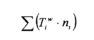
- At torque levels above a calibrated lowest torque Tlow, provided a gear is selected either manually or automatically so that torque is transmitted via the preselected component, e. g. the
sun gear 13, transmission input torque Ti and input speed are sampled at regular intervals, e. g. each 25 ms. Input speed is then recalculated into number of rotations n1 by multiplying with sample time. As an alternative to sampling at regular intervals the number of revolutions n1 at torque levels above Tlow can be counted and accumulated continuously. The accumulated measured duty cycle is memorized in the control unit each time the car ignition is turned off. - The Wöhler number of revolutions Ni is read out from the lookup table indexed by input torque. The
control unit 6 calculates accumulated damage according
to:DCtot being a predetermined level of damage. Ni and ni can be normalised to reach a better calculation accuracy when adding small numbers ni / Ni together.
- When the relation DC/ DCtot exceeds 1 (or unity) the
control unit 6 produces an output warning signal. This signal can be used as an input signal to anindicator 20 on the dashboard of the vehicle, as indicated in Fig. 1, so as to direcly alert the driver that the transmission needs service. As an alternative no indication of the condition of the transmission is provided in the vehicle. Instead the condition of the transmission is checked, e. g. in connection with regular services of the vehicle, by plugging in a test instrument 21 into thecontrol unit 6. - Within the scope of the invention the load situation of all torque transmitting gear sets of a transmission, i. e. in this case also the reaction planetary gear set 11 and the final
drive gear set 12, can be monitored and the estimated wear accumulated, in which case Wöhler diagrams for thesun gear 16 of thegear set 11 and the sun gear 17 of thegear set 12 are established and mapped in table form in thecontrol unit 6 as described above. The accumulated damage of each sun gear is calculated as described above. It is for practical reasons that the measured duty cycles for the sun gears are selected. These are then correlated to the statistic lenght of life of the respective planetary gear set. - The invention has been described above with reference to an automatic transmission but it can of course also be implemented in a vehicle having a manual gearbox and an engine control unit.
Claims (17)
- A method of detecting wear of at least one preselected torque transmitting component in a vehicle transmission comprising an electronic control unit wherein signals representing at least selected gear ratio, transmission input shaft torque and input shaft rotational speed are available in the control unit, characterized byaccumulating a measured duty cycle representative of revolutions and related torque transmitted by said component when running,calculating wear of said component by comparing the accumulated measured duty cycle with a predetermined total duty cycle which represents a predetermined level of wear of said component.
- A method according to claim 1, characterized by basing the predetermined total duty cycle on a Whöler diagram obtained from tests of said preselected torque transmitting component.
- A method according to claim 1 or 2, characterized by accumulating a measured duty cycle only when the preselected torque transmitting component is engaged in transmitting torque.
- A method according to claim 1 or 2, characterized by only accumulating a measured duty cycle at torque levels above a predetermined torque level.
- A method according to one of claims 1-4, characterized by producing an output signal representing the accumulated duty cycle divided by said predetermined total duty cycle.
- A method according to claim 5, characterized by using said output signal as an input signal to indicator means readable inside a vehicle to indicate wear of a transmission mounted in the vehicle.
- A method according to claim 5, characterized by using said output signal as an input signal to indicator means readable outside a vehicle.
- A method according to one of claims 1-7 to detect wear of at least one preselected torque transmitting component in an automatic vehicle transmission having a planetary gearing, characterized in that the sun gear of a planetary gear set is said preselected torque transmitting component
- A method according to claim 8, characterized in that the sun gear of a planetary gear set transmitting torque with the highest gear ratio is said preselected torque transmitting component.
- A method according to one of claims 1-9, characterized in that wear of more than one torque transmitting component is detected.
- A motor vehicle transmission (3) including an electronic control unit (6), signals at least representing selected gear ratio, transmission input shaft torque and input shaft rotational speed being available in the electronic control unit, characterized in that the electronic control unit (6) is arranged to calculate wear of a preselected torque transmitting component of the transmission by accumulating a measured duty cycle (DC) representative of revolutions and related torque transmitted by said component when running and by comparing the accumulated measured duty cycle with a predetermined total duty cycle (DCtot) which represents a predetermined level of wear of said component.
- A transmission according to claim 11, characterized in that in the electronic control unit (6) is stored in table form a Whöler diagram obtained from tests of said torque transmitting component, said predetermined total duty cycle being based on said diagram.
- A transmission according to claim 11 or 12, characterized in that the electronic control unit (6) is arranged to accumulate a measured duty cycle (DC) only when the preselected torque transmitting component is engaged in transmitting torque.
- A transmission according to claim 11-12, characterized in that the electronic control unit (6) is arranged to only accumulate a measured duty cycle (DC) at torque levels above a predetermined torque level (Tlow).
- A transmission according to one of claims 11-14, characterized in that the electronic control unit (6) is arranged to detect wear of more than one torque transmitting component.
- A transmission according to one of claims 11-15 and having a planetary gearing (10,11,12), characterized in that the sun gear (13,16,17) of at least one planetary gear set of said planetary gearing is said preselected torque transmitting component.
- A transmission according to claim 16, characterized in that the sun gear (13) of a planetary gear set (10) transmitting torque with the highest gear ratio is said preselected torque transmitting component
Priority Applications (2)
| Application Number | Priority Date | Filing Date | Title |
|---|---|---|---|
| DE2002614383 DE60214383T2 (en) | 2002-10-07 | 2002-10-07 | Wear detection method in a vehicle transmission and transmission control to determine its wear |
| EP20020445125 EP1408259B1 (en) | 2002-10-07 | 2002-10-07 | A method of detecting wear in a motor vehicle transmission and a transmission provided with means to detect such wear |
Applications Claiming Priority (1)
| Application Number | Priority Date | Filing Date | Title |
|---|---|---|---|
| EP20020445125 EP1408259B1 (en) | 2002-10-07 | 2002-10-07 | A method of detecting wear in a motor vehicle transmission and a transmission provided with means to detect such wear |
Publications (2)
| Publication Number | Publication Date |
|---|---|
| EP1408259A1 true EP1408259A1 (en) | 2004-04-14 |
| EP1408259B1 EP1408259B1 (en) | 2006-08-30 |
Family
ID=32011078
Family Applications (1)
| Application Number | Title | Priority Date | Filing Date |
|---|---|---|---|
| EP20020445125 Expired - Lifetime EP1408259B1 (en) | 2002-10-07 | 2002-10-07 | A method of detecting wear in a motor vehicle transmission and a transmission provided with means to detect such wear |
Country Status (2)
| Country | Link |
|---|---|
| EP (1) | EP1408259B1 (en) |
| DE (1) | DE60214383T2 (en) |
Cited By (7)
| Publication number | Priority date | Publication date | Assignee | Title |
|---|---|---|---|---|
| DE102005008712A1 (en) * | 2005-02-25 | 2006-08-31 | Zf Friedrichshafen Ag | Automatic transmission unit and method for its use, comprising check of system and enabling of additional function after positive feedback |
| WO2008125218A1 (en) * | 2007-04-12 | 2008-10-23 | Wittenstein Ag | Method for optimally operating gearboxes |
| WO2009027255A3 (en) * | 2007-08-24 | 2009-11-05 | Siemens Aktiengesellschaft | A method and system that are used to determine the service life endpoint and evaluate the current historical service life |
| WO2011069495A1 (en) * | 2009-12-10 | 2011-06-16 | Otto Bock Healthcare Gmbh | Mechanically loaded component, in particular orthopaedic aid |
| CN102537285A (en) * | 2012-01-04 | 2012-07-04 | 吉林市航盛宏宇电子有限公司 | Wear monitoring sensor for transmission case of automobile |
| WO2022084058A1 (en) * | 2020-10-21 | 2022-04-28 | Audi Ag | Method for operating a vehicle transmission for a motor vehicle, and corresponding vehicle transmission |
| CN118855967A (en) * | 2024-09-26 | 2024-10-29 | 江苏凯斯盾科技有限公司 | Transmission mechanism of a pedal motor |
Families Citing this family (1)
| Publication number | Priority date | Publication date | Assignee | Title |
|---|---|---|---|---|
| DE102024128277A1 (en) * | 2024-09-30 | 2026-04-02 | Renk Gmbh | Transmissions with transmission control and associated methods |
Citations (6)
| Publication number | Priority date | Publication date | Assignee | Title |
|---|---|---|---|---|
| EP0436974A1 (en) * | 1990-01-11 | 1991-07-17 | Van Doorne's Transmissie B.V. | Method for controlling the tension in a driving belt of a continuously variable transmission |
| US6175793B1 (en) * | 1996-08-07 | 2001-01-16 | Trw Lucas Varity Electric Steering Ltd. | Gearboxes |
| EP1093040A1 (en) * | 1999-10-14 | 2001-04-18 | Voith Turbo GmbH & Co. KG | Diagnostic system and method for determining malfunctions |
| US6225892B1 (en) * | 1999-04-15 | 2001-05-01 | Meritor Heavy Vehicle Systems, Llc | Gear fatigue monitor |
| EP1219867A1 (en) * | 2000-12-27 | 2002-07-03 | Voith Turbo GmbH & Co. KG | Electronic control unit for gearbox |
| EP1225371A2 (en) * | 2001-01-15 | 2002-07-24 | Honda Giken Kogyo Kabushiki Kaisha | Belt replacement timing annunciator for belt-type automatic transmissions |
-
2002
- 2002-10-07 EP EP20020445125 patent/EP1408259B1/en not_active Expired - Lifetime
- 2002-10-07 DE DE2002614383 patent/DE60214383T2/en not_active Expired - Lifetime
Patent Citations (6)
| Publication number | Priority date | Publication date | Assignee | Title |
|---|---|---|---|---|
| EP0436974A1 (en) * | 1990-01-11 | 1991-07-17 | Van Doorne's Transmissie B.V. | Method for controlling the tension in a driving belt of a continuously variable transmission |
| US6175793B1 (en) * | 1996-08-07 | 2001-01-16 | Trw Lucas Varity Electric Steering Ltd. | Gearboxes |
| US6225892B1 (en) * | 1999-04-15 | 2001-05-01 | Meritor Heavy Vehicle Systems, Llc | Gear fatigue monitor |
| EP1093040A1 (en) * | 1999-10-14 | 2001-04-18 | Voith Turbo GmbH & Co. KG | Diagnostic system and method for determining malfunctions |
| EP1219867A1 (en) * | 2000-12-27 | 2002-07-03 | Voith Turbo GmbH & Co. KG | Electronic control unit for gearbox |
| EP1225371A2 (en) * | 2001-01-15 | 2002-07-24 | Honda Giken Kogyo Kabushiki Kaisha | Belt replacement timing annunciator for belt-type automatic transmissions |
Cited By (9)
| Publication number | Priority date | Publication date | Assignee | Title |
|---|---|---|---|---|
| DE102005008712A1 (en) * | 2005-02-25 | 2006-08-31 | Zf Friedrichshafen Ag | Automatic transmission unit and method for its use, comprising check of system and enabling of additional function after positive feedback |
| WO2008125218A1 (en) * | 2007-04-12 | 2008-10-23 | Wittenstein Ag | Method for optimally operating gearboxes |
| US8276450B2 (en) | 2007-04-12 | 2012-10-02 | Wittenstein Ag | Method for optimally operating transmissions |
| WO2009027255A3 (en) * | 2007-08-24 | 2009-11-05 | Siemens Aktiengesellschaft | A method and system that are used to determine the service life endpoint and evaluate the current historical service life |
| CN101373495B (en) * | 2007-08-24 | 2010-09-29 | 西门子公司 | Method and system for determining the end of useful life and estimating current historical useful life |
| WO2011069495A1 (en) * | 2009-12-10 | 2011-06-16 | Otto Bock Healthcare Gmbh | Mechanically loaded component, in particular orthopaedic aid |
| CN102537285A (en) * | 2012-01-04 | 2012-07-04 | 吉林市航盛宏宇电子有限公司 | Wear monitoring sensor for transmission case of automobile |
| WO2022084058A1 (en) * | 2020-10-21 | 2022-04-28 | Audi Ag | Method for operating a vehicle transmission for a motor vehicle, and corresponding vehicle transmission |
| CN118855967A (en) * | 2024-09-26 | 2024-10-29 | 江苏凯斯盾科技有限公司 | Transmission mechanism of a pedal motor |
Also Published As
| Publication number | Publication date |
|---|---|
| DE60214383D1 (en) | 2006-10-12 |
| DE60214383T2 (en) | 2006-12-21 |
| EP1408259B1 (en) | 2006-08-30 |
Similar Documents
| Publication | Publication Date | Title |
|---|---|---|
| US7966115B2 (en) | System and method for controlling transmission shift points based on vehicle weight | |
| US8050814B2 (en) | Apparatus and method for determining remaining transmission oil life | |
| US20080167161A1 (en) | Automatic braking system | |
| KR100243892B1 (en) | Method/system for determination of gross combined weight of vehicles equipped with electronic data links | |
| US20110043348A1 (en) | Shift Prompt System | |
| US10738882B2 (en) | Manual shifting control system and method for multi-speed automatic transmission | |
| US8442732B1 (en) | Method and system for determining a driveline ratio for a powertrain having an auxiliary transmission | |
| CN102224362B (en) | Gear feedback system | |
| EP1908621A1 (en) | Automated inter-axle differential lock sensor configuration and calibration method | |
| EP1408259B1 (en) | A method of detecting wear in a motor vehicle transmission and a transmission provided with means to detect such wear | |
| JP3668908B2 (en) | Method and apparatus for determining a value of a control parameter representing total vehicle weight | |
| US20130166171A1 (en) | System and Method for Controlling an Engine Speed Limit of a Work Vehicle During a Transmission Ratio Change | |
| US6663534B2 (en) | Process for preventing oscillating gearshifting in automatic motor vehicle transmissions by suitable reduction of engine torque | |
| EP1944529A2 (en) | Gear determination apparatus, gear determination method, gear-shift instruction apparatus and gear-shift instruction method | |
| US8682543B2 (en) | Transmission control method | |
| US9791038B2 (en) | Control method of transmission for vehicle and control system for the same | |
| CN102954204A (en) | Driving resistance-dependent shifting delay | |
| US10040456B2 (en) | System and method for hill climbing gear selection | |
| US6205389B1 (en) | Method/system for resetting the value of a control parameter indicative of gross combine weight of vehicles to a default value thereof | |
| EP2478262B1 (en) | Method for determination of numbers of gear steps | |
| EP2478263B1 (en) | Method for determination of numbers of gear steps | |
| US6230554B1 (en) | System and method for determining a performance characteristic of a vehicle component based upon temperature, load, road grade and time | |
| MANUAL | 9-Speed | |
| CN118293211A (en) | Method and device for acquiring gear shifting rule of vehicle, electronic equipment and terminal equipment | |
| CN114063607B (en) | Automotive AMT clutch in-loop test bench and test method thereof |
Legal Events
| Date | Code | Title | Description |
|---|---|---|---|
| PUAI | Public reference made under article 153(3) epc to a published international application that has entered the european phase |
Free format text: ORIGINAL CODE: 0009012 |
|
| AK | Designated contracting states |
Kind code of ref document: A1 Designated state(s): AT BE BG CH CY CZ DE DK EE ES FI FR GB GR IE IT LI LU MC NL PT SE SK TR |
|
| AX | Request for extension of the european patent |
Extension state: AL LT LV MK RO SI |
|
| 17P | Request for examination filed |
Effective date: 20041006 |
|
| AKX | Designation fees paid |
Designated state(s): DE GB SE |
|
| GRAP | Despatch of communication of intention to grant a patent |
Free format text: ORIGINAL CODE: EPIDOSNIGR1 |
|
| GRAS | Grant fee paid |
Free format text: ORIGINAL CODE: EPIDOSNIGR3 |
|
| GRAA | (expected) grant |
Free format text: ORIGINAL CODE: 0009210 |
|
| RAP1 | Party data changed (applicant data changed or rights of an application transferred) |
Owner name: FORD GLOBAL TECHNOLOGIES, LLC |
|
| AK | Designated contracting states |
Kind code of ref document: B1 Designated state(s): DE GB SE |
|
| REG | Reference to a national code |
Ref country code: GB Ref legal event code: FG4D |
|
| REF | Corresponds to: |
Ref document number: 60214383 Country of ref document: DE Date of ref document: 20061012 Kind code of ref document: P |
|
| REG | Reference to a national code |
Ref country code: SE Ref legal event code: TRGR |
|
| PLBE | No opposition filed within time limit |
Free format text: ORIGINAL CODE: 0009261 |
|
| STAA | Information on the status of an ep patent application or granted ep patent |
Free format text: STATUS: NO OPPOSITION FILED WITHIN TIME LIMIT |
|
| 26N | No opposition filed |
Effective date: 20070531 |
|
| REG | Reference to a national code |
Ref country code: GB Ref legal event code: 732E Free format text: REGISTERED BETWEEN 20111020 AND 20111025 |
|
| REG | Reference to a national code |
Ref country code: DE Ref legal event code: R082 Ref document number: 60214383 Country of ref document: DE Representative=s name: HOFFMANN - EITLE, DE |
|
| REG | Reference to a national code |
Ref country code: DE Ref legal event code: R082 Ref document number: 60214383 Country of ref document: DE Representative=s name: HOFFMANN - EITLE, DE Effective date: 20120207 Ref country code: DE Ref legal event code: R081 Ref document number: 60214383 Country of ref document: DE Owner name: VOLVO CAR CORPORATION, SE Free format text: FORMER OWNER: FORD GLOBAL TECHNOLOGIES, LLC, DEARBORN, MICH., US Effective date: 20120207 Ref country code: DE Ref legal event code: R082 Ref document number: 60214383 Country of ref document: DE Representative=s name: HOFFMANN - EITLE PATENT- UND RECHTSANWAELTE PA, DE Effective date: 20120207 |
|
| PGFP | Annual fee paid to national office [announced via postgrant information from national office to epo] |
Ref country code: GB Payment date: 20141015 Year of fee payment: 13 Ref country code: SE Payment date: 20141027 Year of fee payment: 13 Ref country code: DE Payment date: 20141015 Year of fee payment: 13 |
|
| REG | Reference to a national code |
Ref country code: DE Ref legal event code: R119 Ref document number: 60214383 Country of ref document: DE |
|
| REG | Reference to a national code |
Ref country code: SE Ref legal event code: EUG |
|
| GBPC | Gb: european patent ceased through non-payment of renewal fee |
Effective date: 20151007 |
|
| PG25 | Lapsed in a contracting state [announced via postgrant information from national office to epo] |
Ref country code: GB Free format text: LAPSE BECAUSE OF NON-PAYMENT OF DUE FEES Effective date: 20151007 Ref country code: DE Free format text: LAPSE BECAUSE OF NON-PAYMENT OF DUE FEES Effective date: 20160503 |
|
| PG25 | Lapsed in a contracting state [announced via postgrant information from national office to epo] |
Ref country code: SE Free format text: LAPSE BECAUSE OF NON-PAYMENT OF DUE FEES Effective date: 20151008 |