EP1408072A1 - Method of making a material - Google Patents
Method of making a material Download PDFInfo
- Publication number
- EP1408072A1 EP1408072A1 EP20030078204 EP03078204A EP1408072A1 EP 1408072 A1 EP1408072 A1 EP 1408072A1 EP 20030078204 EP20030078204 EP 20030078204 EP 03078204 A EP03078204 A EP 03078204A EP 1408072 A1 EP1408072 A1 EP 1408072A1
- Authority
- EP
- European Patent Office
- Prior art keywords
- surfactant
- polymer
- surface tension
- solution
- bubbles
- Prior art date
- Legal status (The legal status is an assumption and is not a legal conclusion. Google has not performed a legal analysis and makes no representation as to the accuracy of the status listed.)
- Withdrawn
Links
- 239000000463 material Substances 0.000 title claims abstract description 49
- 238000004519 manufacturing process Methods 0.000 title claims abstract description 15
- 239000004094 surface-active agent Substances 0.000 claims abstract description 90
- 229920000642 polymer Polymers 0.000 claims abstract description 36
- 238000000576 coating method Methods 0.000 claims abstract description 25
- 239000011248 coating agent Substances 0.000 claims abstract description 22
- 239000004604 Blowing Agent Substances 0.000 claims abstract description 16
- 238000005187 foaming Methods 0.000 claims abstract description 4
- 238000000034 method Methods 0.000 claims description 32
- 230000003068 static effect Effects 0.000 claims description 17
- 239000004372 Polyvinyl alcohol Substances 0.000 claims description 8
- 229920002451 polyvinyl alcohol Polymers 0.000 claims description 8
- 229920001477 hydrophilic polymer Polymers 0.000 claims description 7
- 238000004220 aggregation Methods 0.000 claims description 6
- 230000002776 aggregation Effects 0.000 claims description 6
- 108010010803 Gelatin Proteins 0.000 claims description 2
- 229920003171 Poly (ethylene oxide) Polymers 0.000 claims description 2
- NBVXSUQYWXRMNV-UHFFFAOYSA-N fluoromethane Chemical group FC NBVXSUQYWXRMNV-UHFFFAOYSA-N 0.000 claims description 2
- 229920000159 gelatin Polymers 0.000 claims description 2
- 239000008273 gelatin Substances 0.000 claims description 2
- 235000019322 gelatine Nutrition 0.000 claims description 2
- 235000011852 gelatine desserts Nutrition 0.000 claims description 2
- 229920000036 polyvinylpyrrolidone Polymers 0.000 claims description 2
- 239000001267 polyvinylpyrrolidone Substances 0.000 claims description 2
- 235000013855 polyvinylpyrrolidone Nutrition 0.000 claims description 2
- 239000000243 solution Substances 0.000 description 23
- 239000006260 foam Substances 0.000 description 21
- 239000007789 gas Substances 0.000 description 18
- NLXLAEXVIDQMFP-UHFFFAOYSA-N Ammonia chloride Chemical compound [NH4+].[Cl-] NLXLAEXVIDQMFP-UHFFFAOYSA-N 0.000 description 8
- LPXPTNMVRIOKMN-UHFFFAOYSA-M sodium nitrite Chemical group [Na+].[O-]N=O LPXPTNMVRIOKMN-UHFFFAOYSA-M 0.000 description 8
- 239000007788 liquid Substances 0.000 description 6
- 230000000694 effects Effects 0.000 description 5
- 235000019270 ammonium chloride Nutrition 0.000 description 4
- 239000007864 aqueous solution Substances 0.000 description 4
- 230000000704 physical effect Effects 0.000 description 4
- 235000010288 sodium nitrite Nutrition 0.000 description 4
- 238000000354 decomposition reaction Methods 0.000 description 3
- 238000001035 drying Methods 0.000 description 3
- 238000010348 incorporation Methods 0.000 description 3
- 238000005259 measurement Methods 0.000 description 3
- 238000001000 micrograph Methods 0.000 description 3
- 239000004005 microsphere Substances 0.000 description 3
- 239000000203 mixture Substances 0.000 description 3
- 238000012545 processing Methods 0.000 description 3
- 238000001878 scanning electron micrograph Methods 0.000 description 3
- IJGRMHOSHXDMSA-UHFFFAOYSA-N Atomic nitrogen Chemical compound N#N IJGRMHOSHXDMSA-UHFFFAOYSA-N 0.000 description 2
- -1 Polyethylene Polymers 0.000 description 2
- 230000010261 cell growth Effects 0.000 description 2
- 239000002666 chemical blowing agent Substances 0.000 description 2
- 238000006243 chemical reaction Methods 0.000 description 2
- 238000007598 dipping method Methods 0.000 description 2
- 238000001125 extrusion Methods 0.000 description 2
- 238000010438 heat treatment Methods 0.000 description 2
- 230000002209 hydrophobic effect Effects 0.000 description 2
- 239000000178 monomer Substances 0.000 description 2
- 229920000139 polyethylene terephthalate Polymers 0.000 description 2
- 239000005020 polyethylene terephthalate Substances 0.000 description 2
- 229920005989 resin Polymers 0.000 description 2
- 239000011347 resin Substances 0.000 description 2
- 238000005979 thermal decomposition reaction Methods 0.000 description 2
- 238000009736 wetting Methods 0.000 description 2
- QTBSBXVTEAMEQO-UHFFFAOYSA-M Acetate Chemical compound CC([O-])=O QTBSBXVTEAMEQO-UHFFFAOYSA-M 0.000 description 1
- NVXKZDHMFXXPAS-UHFFFAOYSA-N CC(C)(CC(COC(C)(C)c1ccc(C)cc1)O)C(C)(C)OCC(CO)C(C)(C)O Chemical compound CC(C)(CC(COC(C)(C)c1ccc(C)cc1)O)C(C)(C)OCC(CO)C(C)(C)O NVXKZDHMFXXPAS-UHFFFAOYSA-N 0.000 description 1
- 0 CCCSC(C)(C)CC(C(C)(C)*)C(NC*O)=O Chemical compound CCCSC(C)(C)CC(C(C)(C)*)C(NC*O)=O 0.000 description 1
- 239000004698 Polyethylene Substances 0.000 description 1
- 239000002253 acid Substances 0.000 description 1
- 230000004913 activation Effects 0.000 description 1
- 238000007754 air knife coating Methods 0.000 description 1
- 239000006265 aqueous foam Substances 0.000 description 1
- 239000011324 bead Substances 0.000 description 1
- 230000015572 biosynthetic process Effects 0.000 description 1
- 238000007664 blowing Methods 0.000 description 1
- 238000009835 boiling Methods 0.000 description 1
- 239000008199 coating composition Substances 0.000 description 1
- 238000000748 compression moulding Methods 0.000 description 1
- 238000007796 conventional method Methods 0.000 description 1
- 238000005336 cracking Methods 0.000 description 1
- 239000003431 cross linking reagent Substances 0.000 description 1
- 238000007766 curtain coating Methods 0.000 description 1
- 238000009792 diffusion process Methods 0.000 description 1
- 239000003822 epoxy resin Substances 0.000 description 1
- LNEPOXFFQSENCJ-UHFFFAOYSA-N haloperidol Chemical compound C1CC(O)(C=2C=CC(Cl)=CC=2)CCN1CCCC(=O)C1=CC=C(F)C=C1 LNEPOXFFQSENCJ-UHFFFAOYSA-N 0.000 description 1
- 238000003384 imaging method Methods 0.000 description 1
- 238000002347 injection Methods 0.000 description 1
- 239000007924 injection Substances 0.000 description 1
- 239000000976 ink Substances 0.000 description 1
- 239000000155 melt Substances 0.000 description 1
- 229910052757 nitrogen Inorganic materials 0.000 description 1
- 230000006911 nucleation Effects 0.000 description 1
- 238000010899 nucleation Methods 0.000 description 1
- 239000011368 organic material Substances 0.000 description 1
- 239000000049 pigment Substances 0.000 description 1
- 229920000647 polyepoxide Polymers 0.000 description 1
- 229920000573 polyethylene Polymers 0.000 description 1
- 229920002635 polyurethane Polymers 0.000 description 1
- 239000004814 polyurethane Substances 0.000 description 1
- 239000004800 polyvinyl chloride Substances 0.000 description 1
- 229920000915 polyvinyl chloride Polymers 0.000 description 1
- 239000011148 porous material Substances 0.000 description 1
- 238000007639 printing Methods 0.000 description 1
- 238000003672 processing method Methods 0.000 description 1
- 238000010926 purge Methods 0.000 description 1
- 238000010107 reaction injection moulding Methods 0.000 description 1
- 239000002904 solvent Substances 0.000 description 1
- 229920003002 synthetic resin Polymers 0.000 description 1
- 239000000057 synthetic resin Substances 0.000 description 1
- 238000012360 testing method Methods 0.000 description 1
- 239000012815 thermoplastic material Substances 0.000 description 1
- XLYOFNOQVPJJNP-UHFFFAOYSA-N water Substances O XLYOFNOQVPJJNP-UHFFFAOYSA-N 0.000 description 1
Images


Classifications
-
- B—PERFORMING OPERATIONS; TRANSPORTING
- B41—PRINTING; LINING MACHINES; TYPEWRITERS; STAMPS
- B41M—PRINTING, DUPLICATING, MARKING, OR COPYING PROCESSES; COLOUR PRINTING
- B41M5/00—Duplicating or marking methods; Sheet materials for use therein
- B41M5/50—Recording sheets characterised by the coating used to improve ink, dye or pigment receptivity, e.g. for ink-jet or thermal dye transfer recording
- B41M5/52—Macromolecular coatings
- B41M5/5254—Macromolecular coatings characterised by the use of polymers obtained by reactions only involving carbon-to-carbon unsaturated bonds, e.g. vinyl polymers
-
- B—PERFORMING OPERATIONS; TRANSPORTING
- B41—PRINTING; LINING MACHINES; TYPEWRITERS; STAMPS
- B41M—PRINTING, DUPLICATING, MARKING, OR COPYING PROCESSES; COLOUR PRINTING
- B41M5/00—Duplicating or marking methods; Sheet materials for use therein
- B41M5/50—Recording sheets characterised by the coating used to improve ink, dye or pigment receptivity, e.g. for ink-jet or thermal dye transfer recording
- B41M5/52—Macromolecular coatings
-
- B—PERFORMING OPERATIONS; TRANSPORTING
- B41—PRINTING; LINING MACHINES; TYPEWRITERS; STAMPS
- B41M—PRINTING, DUPLICATING, MARKING, OR COPYING PROCESSES; COLOUR PRINTING
- B41M5/00—Duplicating or marking methods; Sheet materials for use therein
- B41M5/50—Recording sheets characterised by the coating used to improve ink, dye or pigment receptivity, e.g. for ink-jet or thermal dye transfer recording
- B41M5/52—Macromolecular coatings
- B41M5/5236—Macromolecular coatings characterised by the use of natural gums, of proteins, e.g. gelatins, or of macromolecular carbohydrates, e.g. cellulose
-
- B—PERFORMING OPERATIONS; TRANSPORTING
- B41—PRINTING; LINING MACHINES; TYPEWRITERS; STAMPS
- B41M—PRINTING, DUPLICATING, MARKING, OR COPYING PROCESSES; COLOUR PRINTING
- B41M5/00—Duplicating or marking methods; Sheet materials for use therein
- B41M5/50—Recording sheets characterised by the coating used to improve ink, dye or pigment receptivity, e.g. for ink-jet or thermal dye transfer recording
- B41M5/52—Macromolecular coatings
- B41M5/5227—Macromolecular coatings characterised by organic non-macromolecular additives, e.g. UV-absorbers, plasticisers, surfactants
-
- B—PERFORMING OPERATIONS; TRANSPORTING
- B41—PRINTING; LINING MACHINES; TYPEWRITERS; STAMPS
- B41M—PRINTING, DUPLICATING, MARKING, OR COPYING PROCESSES; COLOUR PRINTING
- B41M5/00—Duplicating or marking methods; Sheet materials for use therein
- B41M5/50—Recording sheets characterised by the coating used to improve ink, dye or pigment receptivity, e.g. for ink-jet or thermal dye transfer recording
- B41M5/52—Macromolecular coatings
- B41M5/529—Macromolecular coatings characterised by the use of fluorine- or silicon-containing organic compounds
Definitions
- the present invention relates to a method of making a material and in particular to a method of making a foamed material i.e. a material including a foam such as a material suitable for use as an inkjet receiving medium.
- polymer foams are manufactured using mostly hydrophobic thermoplastic materials such as Polyurethane, PVC and Polyethylene, which require high processing temperatures.
- a gas-filled polymer Prior to forming the foam a gas-filled polymer must be formed.
- thermal decomposition of chemical blowing agents include thermal decomposition of chemical blowing agents, mechanical whipping of gases into a polymer melt, use of low boiling point liquids, expansion of a gas dissolved in a polymer upon reduction of pressure in the system and the incorporation of microspheres into a polymer mass.
- Thermal decomposition of chemical blowing agents can be achieved by application of heat or as a result of the exothermic heat of reaction during polymerisation.
- the decomposition generates a gas such as N 2 or CO 2 , which forms a gas-filled polymer.
- a gas such as N 2 or CO 2
- Incorporation of microspheres into a polymer mass relies on the incorporation of microspheres of a first gas-filled polymer into a polymer mass followed by heating of the mixture to cause expansion of the first gas-filled polymer to form a second gas-filled polymer.
- the foam is then formed using one of three common manufacturing processes: compression moulding, reaction injection moulding or extrusion of the foam.
- the temperatures involved in these processes can be very high, e.g. in excess of 150°C, as the polymers used are in their molten state.
- the most common processing method used in creating polymer foam is extrusion. This is a three-stage operation consisting of forming a polymer solution with gas dissolved in it to create a single-phase solution.
- the gas may be dissolved by injection of N 2 or CO 2 , or by the use of blowing agent. Nucleation sites are then formed, as a result of a rapid pressure drop to create large numbers of uniform sites. Cell growth then takes place by means of diffusion of the gas to form bubbles. Processing conditions provide pressure and temperature changes necessary to control cell growth.
- a polymer foam can be created in two ways. In a first way voids are produced by generating gas in an aqueous coating solution of a hydrophilic polymer. In a second way an aqueous solution of hydrophilic polymer is coated onto a support, voids being created in the solution after the coating process during the setting and drying of the foam.
- a coating solution comprising an aqueous solution of a polymer and blowing agent, the solution being treated so that micro-bubbles are formed therein.
- the coating solution being a liquid composition containing micro-bubbles, is then coated onto a support.
- the micro bubbles may be formed in the coating solution by heating the solution to promote the decomposition of the blowing agent to form a gas, or by the addition of an acid to react with the blowing agent to again form a gas within the solution.
- a solution comprising a polymer and a blowing agent is coated onto a support.
- the coated support is then heated to a suitable temperature to cause activation of the blowing agent during the setting and drying of the coating.
- the size of the bubbles formed in the solution and consequently in the foamed material can affect the physical properties of the foam.
- the size of the bubbles effects the absorbency of the foamed material. This is important when the material is used as an inkjet-recording medium.
- United States Patent application number US 2002/0057323 in the names of Yasuo Kurachi, Eiichi Ueda, Takayuki Sasaki and Akihisa Nakajima entitled "Inkjet-recording material” relates to a glossy voided inkjet receiver, which combines good drytime and water resistance with minimal cracking. It discloses a 2-layer product where at least 30% of the voids in the material are formed by using a foaming reaction in a layer comprised of organic materials such as synthetic resin monomers and epoxy resins.
- a method of making a material is required that enables the size of the bubbles formed in the material to be controlled.
- the size of the bubbles formed in the solution used in the making of a foamed material and consequently in the foamed material itself can affect the physical properties of the material.
- the size of the bubbles effects the absorbency of the foamed material.
- inkjet-recording medium This is important when the material is used as an inkjet-recording medium.
- differing bubble sizes may be preferred. For example when designing a medium for use with pigmented inks, larger bubbles may be required as pigments tend to block small pores.
- the bubble size could also be chosen to ensure that the created material has a required level of gloss, since the smaller the bubbles, the glossier a surface of a material tends to be. Accordingly a method of making a material is required that enables the size of the bubbles formed in the material to be controlled.
- a method of making a material comprising the steps of coating a support with a solution comprising a polymer, a blowing agent and a surfactant; and, either prior to or after the step of coating said support, interacting with said solution to cause said blowing agent to generate bubbles within the solution, thus causes foaming of the polymer.
- the surfactant is selected in dependence on whether or not it satisfies one or more predetermined criteria, to control the size of the bubbles.
- a material such as an inkjet-recording medium, formed using the method of the first aspect of the present invention.
- the present invention provides a method by which the size of the voids in the foamed material can be modified through the selection and use of a surfactant in dependence on whether or not the surfactant satisfies one or more predetermined criteria.
- a surfactant in dependence on whether or not the surfactant satisfies one or more predetermined criteria.
- the invention provides a simple and robust method by which control of bubble size may be achieved which is desirable for controlling the average size of bubbles in a polymer foam.
- the average bubble size affects the physical properties of the foam and so depending on the application that the material is being used for, differing bubble sizes may be preferred.
- Another aspect of the present invention provides a material made using the method of the present invention.
- the material may be made having a predetermined bubble size in the foam, such that physical properties of the material that depend on bubble size may be selected.
- the present invention provides a material and a method of making the material, in which the method includes the step of selecting a surfactant to add to a coating solution used in the manufacture of the material.
- the coating solution is typically a solution (e.g. an aqueous solution) of a polymer such as a hydrophilic polymer.
- hydrophilic polymers include amongst others polyvinyl alcohol, polyethylene oxide, polyvinylpyrrolidone and gelatin.
- a suitable support such as resin-coated paper, film base, acetate, polyethylene terephthalate PET, printing plate is then coated with the coating solution using a conventional coating method. Any suitable coating method may be used including include amongst others, curtain coating, bead coating or air knife coating.
- the polymer foam is formed by the addition of a blowing agent to an aqueous solution of a hydrophilic polymer, followed by the application of heat to the solution to cause decomposition of the blowing agent and the consequent generation of gas bubbles.
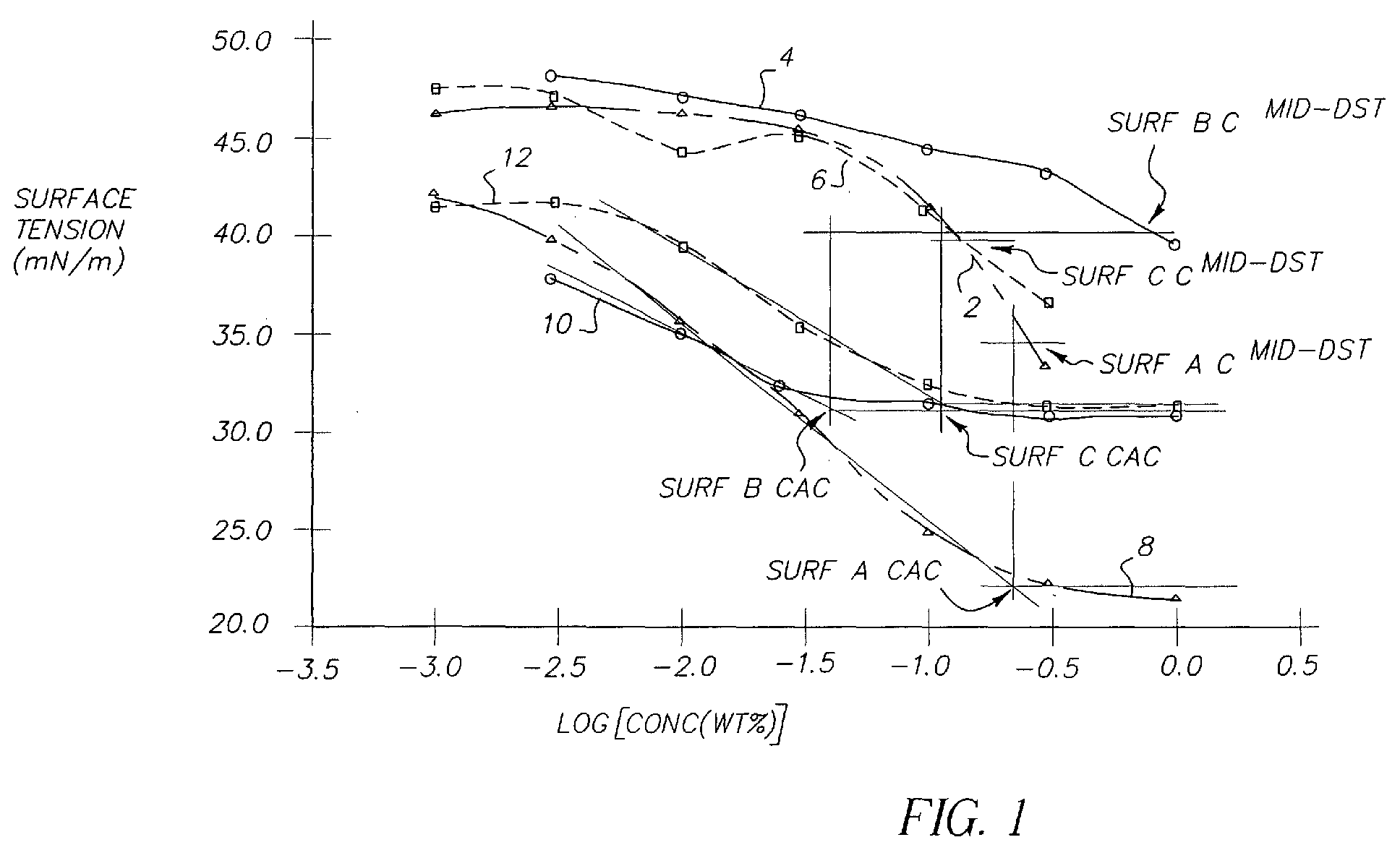
- Figure 1 shows a graph of variation in log(concentration of a surfactant) against both dynamic and static surface tension for three different surfactants Surf A, Surf B, and Surf C.
- Lines 2, 4 and 6 are the relationships between the variation in dynamic surface tension with changing logarithm of the concentration of surfactant for each of surfactants Surf A, Surf B and Surf C respectively.
- Lines 8, 10 and 12 are the relationships between the variation in static surface tension with changing logarithm of the concentration of surfactant for each of surfactants Surf A, Surf B and Surf C respectively.
- the logarithm corresponding to the critical aggregation concentration CAC of each surfactant is identified as follows. A straight line fit is applied to the region of maximum slope of the static surface tension (SST) curves 8,10 and 12. Another straight line fit is applied to the region of the SST curve where the surface tension has levelled out at or close to a minimum value. The point at which these two lines intersect represents a logarithm value of a corresponding concentration, the concentration being known as the critical aggregation concentration, or CAC.
- Figure 1 shows a graph of variation in log(concentration of a surfactant) against both dynamic and static surface tension for three different surfactants. Accordingly, in this example, the CAC is represented by a log value.
- log C mid-DST log C mid-DST
- surfactant B For surfactant B, it can be seen that the logarithm of its CAC is much lower than the logarithm of the concentration corresponding to its C mid-DST and that its static surface tension levels out at much higher values than surfactant A.
- the average bubble size produced by surfactant B is significantly larger than that achieved with surfactant A.
- the logarithm of the CAC of surfactant C is almost co-incident with the logarithm of the concentration corresponding to its C mid-DST , its static surface tension levels out at a relatively high value like surfactant B, and like surfactant B results in much larger bubbles.
- the logarithm of the CAC of a surfactant used needs to be close in value to the logarithm of the concentration corresponding to C mid-DST for that surfactant and that a low static surface tension of the surfactant is also required.
- the graph in Figure 1 was shown with a linear scale as opposed to a log scale, the condition would be that the CAC must be close in value to C mid-DST .
- the logarithm of its CAC needs to be within 0.5 log units, preferably within 0.25 log units of the logarithm of the concentration corresponding to the C mid-DST .
- a low static surface tension means a value less than 28mN/m, preferably less than 24mN/m. If only one of these criteria is achieved, much larger bubbles are produced.
- the CAC of the surfactant must be of similar concentration to that associated with the midpoint of its dynamic surface tension curve C mid-DST , which may be measured by a specified overflowing cylinder method; and secondly, the surfactant must also have a low static surface tension. If either the difference between the CAC and C mid-DST is too great i.e. greater than 0.5 log units, or the static surface tension is too high i.e. greater than 28mN/m, larger bubbles are formed.
- the use of one or more surfactants to control the size of bubbles or voids in an ink-jet receiver may be controlled by selecting the surfactant or mixture of surfactants such that a desired bubble size is achieved. Without being bound by theory, it is believed that making use of certain properties of surfactants can allow bubble size to be controlled. In particular, it is believed that the CAC, SST and DST (as defmed above) of the surfactants, and the inter-relationship between them can form the basis from which a surfactant may be chosen to enable a desired bubble size.
- the surfactant may be chosen to control bubble size according to certain properties of the surfactant, and, in particular, the CAC, SSC and DST and their inter-relationship as discussed above. More preferably, the surfactant is chosen such that it meets certain predetermined criteria relating to the properties of the surfactant such that the desired size of bubbles is formed in the ink-jet receiver.
- the surfactant may be any suitable surfactant that meets the criteria discussed above, it is preferable that the surfactant is selected from Surfactant A, Surfactant B and Surfactant C, where these surfactants are as defined below, according to the desired bubble size.
- the blowing agent is selected from sodium nitrite and ammonium chloride
- a resin-coated paper support was coated on one side with three layers. Each layer comprised of polyvinyl alcohol (PVA), blowing agents (a total of 50% by weight compared to the PVA laydown) and some surfactant.
- PVA polyvinyl alcohol
- blowing agents a total of 50% by weight compared to the PVA laydown
- surfactant some surfactant.
- the layer nearest the support consisted of 6.1 g/m 2 of PVA, 1.72 g/m 2 of sodium nitrite, 1.33 g/m 2 of ammonium chloride and 0.106 g/m 2 of surfactant.
- the middle layer consisted of 6.7 g/m 2 of PVA, 1.89 g/m 2 of sodium nitrite, 1.46 g/m 2 of ammonium chloride and 0.212 g/m 2 of surfactant.
- the top layer consisted of 7.3 g/m 2 of PVA, 2.06 g/m 2 of sodium nitrite, 1.59 g/m 2 of ammonium chloride and 0.318 g/m 2 of surfactant.
- the three layers were then coated simultaneously on a bead-coating machine using a standard slide hopper.
- the dryers inside the coating track were set to 90°C through which the coating of this invention and the control were passed.
- Rf is a range of fluorocarbon chain lengths based on the general structure C n F 2n+1 , where typically n possesses the following series of values, 6, 8, 10, 12, and 14.
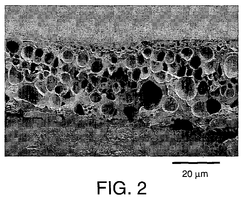
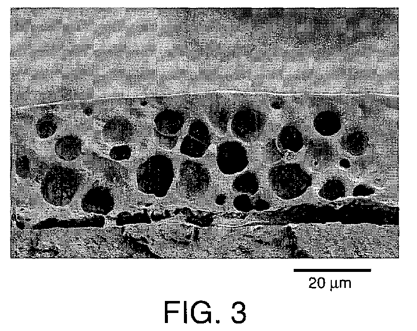
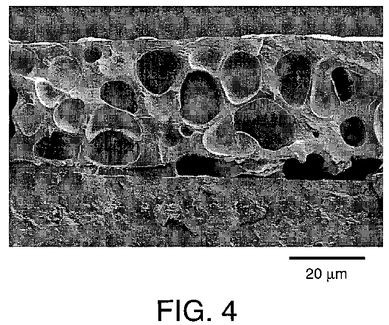
- the scanning electron micrographs shown in Figures 2 to 4 are sections through the resultant materials formed using surfactants Surf A, Surf B and Surf C respectively.
- the micrographs indicate that Surf A (Fig 2) produces bubbles that are considerably smaller than those produced by Surf B (Fig 3) and Surf C (Fig 4).
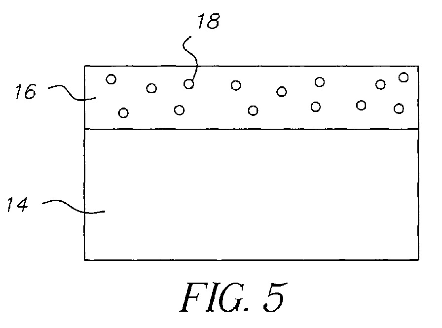
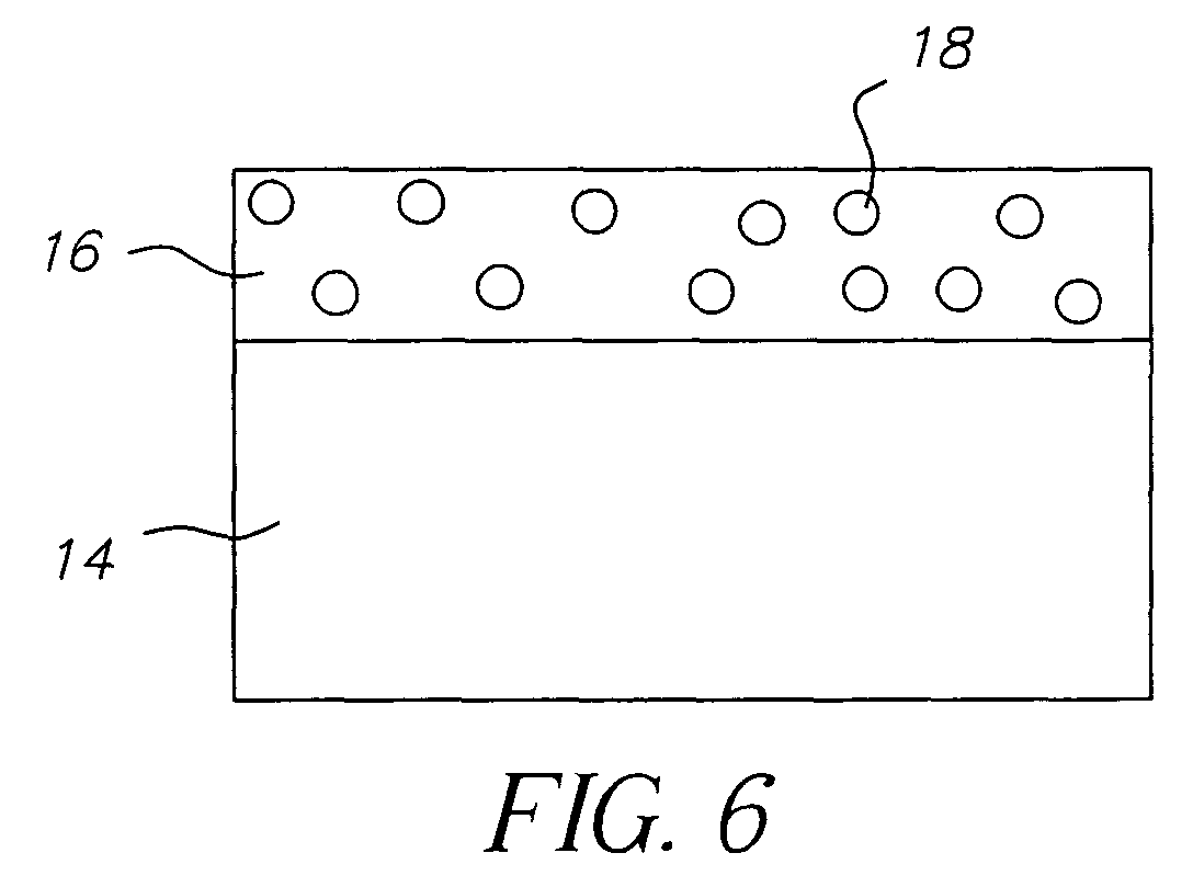
- the scanning electron micrographs are drawn schematically in Figures 5 to 7, corresponding respectively to Figures 2 to 4.
- a support 14 is covered with a layer 16 of foamed polymer. It can be seen that the bubbles 18 are larger in the material formed using Surf B than those in the material formed using Surf A. Similarly, the bubbles in the material formed using Surf C are larger than those in the material formed using Surf A.
- Table 1 shows the average bubble size that is achieved when using each of the surfactants.
- Surfactant Average Bubble Size ( ⁇ m) A 5.35 B 11.88 C 14.53
- the bubble size was measured by placing a randomly chosen area of each coating under the light microscope and a micrograph was then taken using image analysis software (Soft Imaging System, SiS). Prior to taking the micrograph, the software was set to the chosen magnification that had previously been accredited using accredited stage micrometer A818. The diameter of ten randomly chosen bubbles was then measured and the average size calculated.
- image analysis software Soft Imaging System, SiS.
- any suitable method may be used to measure dynamic and static surface tension of liquids.
- the surface tensions of a range of concentrations of the test surfactant are measured in the trial coating composition under a standard set of conditions at 40°C.
- the concentration of the surfactant was usually varied from 0.001 to 1 wt% in log concentration intervals of ⁇ 0.5. Higher or intermediate concentrations were sometimes measured as necessary to improve estimates of critical aggregation concentration or the midpoint of the dynamic surface tension curve.
- Both the static surface tension SST and dynamic surface tension DST measurements were made using the Wilhelmy blade method as described by Padday, J F, 2 nd Int. Congress of Surface Activity, Butterworths, 1957, 1, 1.
- the DST measurements were made with an overflowing circular cylinder, having a diameter of 37.5 mm and a liquid overflow rate of ⁇ 9 ml/sec.
- the data were obtained by raising the surface of the flowing liquid until it just touched the Wilhelmy blade, momentarily dipping the blade by electromechanical means to induce wetting, and taking a final reading 60 seconds later.
- Other suitable methods of measuring dynamic surface tension would be any technique that offers similar dynamic time scales (surface age) i.e. of the order of 0.05 to 0.25 seconds. Examples include the maximum bubble pressure method and the falling curtain method.
- SST measurements were not true equilibrium values, but values taken after a defined period. SST values were obtained by, stopping the flow in the dynamic cell, waiting 30 seconds, raising the surface of the liquid until it just touches the Wilhelmy blade, momentarily dipping the blade by electromechanical means to induce wetting, and taking a final reading 60 seconds later, i.e. 90 seconds after stopping the flow.
Landscapes
- Health & Medical Sciences (AREA)
- Life Sciences & Earth Sciences (AREA)
- General Health & Medical Sciences (AREA)
- Molecular Biology (AREA)
- Chemical & Material Sciences (AREA)
- Chemical Kinetics & Catalysis (AREA)
- Ink Jet Recording Methods And Recording Media Thereof (AREA)
- Application Of Or Painting With Fluid Materials (AREA)
- Manufacture Of Porous Articles, And Recovery And Treatment Of Waste Products (AREA)
- Ink Jet (AREA)
Abstract
The invention provides a method of making a material comprising the steps of:
coating a support with a solution comprising a polymer, a blowing agent and a
surfactant. Either prior to or after the step of coating the support, the solution is
interacted with to cause the blowing agent to generate bubbles within the solution
causing foaming of the polymer. The surfactant is selected in dependence on
whether or not it satisfies one or more predetermined criteria, to control the size of
the bubbles.
Description
- The present invention relates to a method of making a material and in particular to a method of making a foamed material i.e. a material including a foam such as a material suitable for use as an inkjet receiving medium.
- Traditionally polymer foams are manufactured using mostly hydrophobic thermoplastic materials such as Polyurethane, PVC and Polyethylene, which require high processing temperatures. Prior to forming the foam a gas-filled polymer must be formed. There are a number of typical methods of forming a gas-filled polymer which include thermal decomposition of chemical blowing agents, mechanical whipping of gases into a polymer melt, use of low boiling point liquids, expansion of a gas dissolved in a polymer upon reduction of pressure in the system and the incorporation of microspheres into a polymer mass. Thermal decomposition of chemical blowing agents can be achieved by application of heat or as a result of the exothermic heat of reaction during polymerisation. The decomposition generates a gas such as N2 or CO2, which forms a gas-filled polymer. Incorporation of microspheres into a polymer mass relies on the incorporation of microspheres of a first gas-filled polymer into a polymer mass followed by heating of the mixture to cause expansion of the first gas-filled polymer to form a second gas-filled polymer.
- After obtaining the gas-filled polymer by the any of the methods described above, the foam is then formed using one of three common manufacturing processes: compression moulding, reaction injection moulding or extrusion of the foam. The temperatures involved in these processes can be very high, e.g. in excess of 150°C, as the polymers used are in their molten state.
- The most common processing method used in creating polymer foam is extrusion. This is a three-stage operation consisting of forming a polymer solution with gas dissolved in it to create a single-phase solution. The gas may be dissolved by injection of N2 or CO2, or by the use of blowing agent. Nucleation sites are then formed, as a result of a rapid pressure drop to create large numbers of uniform sites. Cell growth then takes place by means of diffusion of the gas to form bubbles. Processing conditions provide pressure and temperature changes necessary to control cell growth.
- Our co-pending UK patent application number 0218507.2 entitled A Method of Making a Material describes a method of making polymer foams using very low processing temperatures in comparison to conventional methods. In the method a polymer foam can be created in two ways. In a first way voids are produced by generating gas in an aqueous coating solution of a hydrophilic polymer. In a second way an aqueous solution of hydrophilic polymer is coated onto a support, voids being created in the solution after the coating process during the setting and drying of the foam.
- To create voids by generating gas in the coating solution, a coating solution is prepared comprising an aqueous solution of a polymer and blowing agent, the solution being treated so that micro-bubbles are formed therein. The coating solution, being a liquid composition containing micro-bubbles, is then coated onto a support. The micro bubbles may be formed in the coating solution by heating the solution to promote the decomposition of the blowing agent to form a gas, or by the addition of an acid to react with the blowing agent to again form a gas within the solution.
- To generate voids post coating during the setting and drying process, a solution comprising a polymer and a blowing agent is coated onto a support. The coated support is then heated to a suitable temperature to cause activation of the blowing agent during the setting and drying of the coating.
- The size of the bubbles formed in the solution and consequently in the foamed material can affect the physical properties of the foam. For example, the size of the bubbles effects the absorbency of the foamed material. This is important when the material is used as an inkjet-recording medium.
- United States Patent application number US 2002/0057323 in the names of Yasuo Kurachi, Eiichi Ueda, Takayuki Sasaki and Akihisa Nakajima entitled "Inkjet-recording material" relates to a glossy voided inkjet receiver, which combines good drytime and water resistance with minimal cracking. It discloses a 2-layer product where at least 30% of the voids in the material are formed by using a foaming reaction in a layer comprised of organic materials such as synthetic resin monomers and epoxy resins.
- The article entitled "Formation of polymeric foams from aqueous foams stabilised using a polymerisable surfactant" by Palani Raj WR, Sasthav M, Cheung HM, of Akron University, published in the Journal of Applied Polymer Science; 49,
No 8, 20th Aug 1993, P. 1453-70 describes the creation of stable polymeric foams by purging an aqueous system (made up of a hydrophobic monomer, a polymerisable surfactant and a crosslinking agent) with nitrogen. - A method of making a material is required that enables the size of the bubbles formed in the material to be controlled. As explained above, the size of the bubbles formed in the solution used in the making of a foamed material and consequently in the foamed material itself can affect the physical properties of the material. For example, the size of the bubbles effects the absorbency of the foamed material.
- This is important when the material is used as an inkjet-recording medium. Depending on the application that the inkjet-recording medium is being designed for, differing bubble sizes may be preferred. For example when designing a medium for use with pigmented inks, larger bubbles may be required as pigments tend to block small pores.
- The bubble size could also be chosen to ensure that the created material has a required level of gloss, since the smaller the bubbles, the glossier a surface of a material tends to be. Accordingly a method of making a material is required that enables the size of the bubbles formed in the material to be controlled.
- According to a first aspect of the present invention, there is provided a method of making a material comprising the steps of coating a support with a solution comprising a polymer, a blowing agent and a surfactant; and, either prior to or after the step of coating said support, interacting with said solution to cause said blowing agent to generate bubbles within the solution, thus causes foaming of the polymer. The surfactant is selected in dependence on whether or not it satisfies one or more predetermined criteria, to control the size of the bubbles.
- According to a second aspect of the present invention, there is provided a material, such as an inkjet-recording medium, formed using the method of the first aspect of the present invention.
- The present invention provides a method by which the size of the voids in the foamed material can be modified through the selection and use of a surfactant in dependence on whether or not the surfactant satisfies one or more predetermined criteria. In particular, it has been found that by choosing an appropriate surfactant, the size of the bubbles in a polymer foam can be adjusted.
- In other words, the invention provides a simple and robust method by which control of bubble size may be achieved which is desirable for controlling the average size of bubbles in a polymer foam. As explained above, the average bubble size affects the physical properties of the foam and so depending on the application that the material is being used for, differing bubble sizes may be preferred.
- Another aspect of the present invention provides a material made using the method of the present invention. The material may be made having a predetermined bubble size in the foam, such that physical properties of the material that depend on bubble size may be selected.
- Examples of the present invention will now be described with reference to the accompanying drawings, in which:
- Figure 1 shows a graph of variation in log(concentration of a surfactant) against surface tension for a number of different surfactants;
- Figures 2 to 4 show scanning electron micrographs of sections through materials according to the present invention; and,
- Figures 5 to 7 show schematic representations of sections through three different materials made according to the method of the present invention.
-
- The present invention provides a material and a method of making the material, in which the method includes the step of selecting a surfactant to add to a coating solution used in the manufacture of the material. The coating solution is typically a solution (e.g. an aqueous solution) of a polymer such as a hydrophilic polymer. Examples of hydrophilic polymers include amongst others polyvinyl alcohol, polyethylene oxide, polyvinylpyrrolidone and gelatin. A suitable support such as resin-coated paper, film base, acetate, polyethylene terephthalate PET, printing plate is then coated with the coating solution using a conventional coating method. Any suitable coating method may be used including include amongst others, curtain coating, bead coating or air knife coating. By choosing an appropriate surfactant, it has been found that the size of the bubbles in a polymer foam can be controlled. Accordingly, by selecting an alternative surfactant, the size of the bubbles in the polymer foam can be selectively adjusted.
- In a method according to the present invention of manufacturing a foamed material including a polymer foam, the polymer foam is formed by the addition of a blowing agent to an aqueous solution of a hydrophilic polymer, followed by the application of heat to the solution to cause decomposition of the blowing agent and the consequent generation of gas bubbles. Such a method is described in detail in our co-pending UK Patent application number 0218507.2 entitled "A Method of Making a Material", the entire contents of which are incorporated herein by reference.
- According to the present invention selection of a surfactant for addition to the solution enables control of the size of bubbles formed in the material. Figure 1 shows a graph of variation in log(concentration of a surfactant) against both dynamic and static surface tension for three different surfactants Surf A, Surf B, and Surf C. Lines 2, 4 and 6 are the relationships between the variation in dynamic surface tension with changing logarithm of the concentration of surfactant for each of surfactants Surf A, Surf B and Surf C respectively.
Lines - For each of the surfactants, two different parameters are determined based on the relationships shown by lines 2 to 12. Firstly, the logarithm corresponding to the critical aggregation concentration CAC of each surfactant is identified as follows. A straight line fit is applied to the region of maximum slope of the static surface tension (SST) curves 8,10 and 12. Another straight line fit is applied to the region of the SST curve where the surface tension has levelled out at or close to a minimum value. The point at which these two lines intersect represents a logarithm value of a corresponding concentration, the concentration being known as the critical aggregation concentration, or CAC. As explained above, Figure 1 shows a graph of variation in log(concentration of a surfactant) against both dynamic and static surface tension for three different surfactants. Accordingly, in this example, the CAC is represented by a log value.
- Secondly, the log of the concentration corresponding to the midpoint of the dynamic surface tension (DST) curve, log Cmid-DST, is interpolated from the point on the DST curve 2, 4 and 6 where the surface tension is midway between that of the solvent i.e. the maximum dynamic surface tension and the value at the CAC i.e. minimum static surface tension.
- It can be seen from the Figure that the logarithm of the CAC of surfactant A is almost co-incident with the logarithm of the concentration corresponding to its Cmid-DST. Surfactant A also gives a low static surface tension at the concentrations that these surfactants are commonly used at, i.e. log[conc(wt%)] = -0.5. From table 1 below, it can also be seen that this surfactant produces the smallest bubbles.
- For surfactant B, it can be seen that the logarithm of its CAC is much lower than the logarithm of the concentration corresponding to its Cmid-DST and that its static surface tension levels out at much higher values than surfactant A. The average bubble size produced by surfactant B is significantly larger than that achieved with surfactant A. Although like surfactant A, the logarithm of the CAC of surfactant C is almost co-incident with the logarithm of the concentration corresponding to its Cmid-DST, its static surface tension levels out at a relatively high value like surfactant B, and like surfactant B results in much larger bubbles.
- From this data, it is demonstrated that to achieve smaller bubbles the logarithm of the CAC of a surfactant used, needs to be close in value to the logarithm of the concentration corresponding to Cmid-DST for that surfactant and that a low static surface tension of the surfactant is also required. If the graph in Figure 1 was shown with a linear scale as opposed to a log scale, the condition would be that the CAC must be close in value to Cmid-DST. Typically, for a surfactant that satisfies this criterion, the logarithm of its CAC needs to be within 0.5 log units, preferably within 0.25 log units of the logarithm of the concentration corresponding to the Cmid-DST. A low static surface tension means a value less than 28mN/m, preferably less than 24mN/m. If only one of these criteria is achieved, much larger bubbles are produced.
- In other words, for small bubbles to be formed in the foam and material two criteria have to be met: First, the CAC of the surfactant must be of similar concentration to that associated with the midpoint of its dynamic surface tension curve Cmid-DST, which may be measured by a specified overflowing cylinder method; and secondly, the surfactant must also have a low static surface tension. If either the difference between the CAC and Cmid-DST is too great i.e. greater than 0.5 log units, or the static surface tension is too high i.e. greater than 28mN/m, larger bubbles are formed.
- In a further aspect of the invention, there is provided the use of one or more surfactants to control the size of bubbles or voids in an ink-jet receiver. The bubble size may be controlled by selecting the surfactant or mixture of surfactants such that a desired bubble size is achieved. Without being bound by theory, it is believed that making use of certain properties of surfactants can allow bubble size to be controlled. In particular, it is believed that the CAC, SST and DST (as defmed above) of the surfactants, and the inter-relationship between them can form the basis from which a surfactant may be chosen to enable a desired bubble size. Preferably, therefore, the surfactant may be chosen to control bubble size according to certain properties of the surfactant, and, in particular, the CAC, SSC and DST and their inter-relationship as discussed above. More preferably, the surfactant is chosen such that it meets certain predetermined criteria relating to the properties of the surfactant such that the desired size of bubbles is formed in the ink-jet receiver.
- Whilst the surfactant may be any suitable surfactant that meets the criteria discussed above, it is preferable that the surfactant is selected from Surfactant A, Surfactant B and Surfactant C, where these surfactants are as defined below, according to the desired bubble size.
- Preferably the blowing agent is selected from sodium nitrite and ammonium chloride
- To demonstrate the invention, materials were prepared as follows:
- A resin-coated paper support was coated on one side with three layers. Each layer comprised of polyvinyl alcohol (PVA), blowing agents (a total of 50% by weight compared to the PVA laydown) and some surfactant.
- The layer nearest the support consisted of 6.1 g/m2 of PVA, 1.72 g/m2 of sodium nitrite, 1.33 g/m2 of ammonium chloride and 0.106 g/m2 of surfactant. The middle layer consisted of 6.7 g/m2 of PVA, 1.89 g/m2 of sodium nitrite, 1.46 g/m2 of ammonium chloride and 0.212 g/m2 of surfactant. The top layer consisted of 7.3 g/m2 of PVA, 2.06 g/m2 of sodium nitrite, 1.59 g/m2 of ammonium chloride and 0.318 g/m2 of surfactant. The three layers were then coated simultaneously on a bead-coating machine using a standard slide hopper.
- To initiate the blowing process, the dryers inside the coating track were set to 90°C through which the coating of this invention and the control were passed.
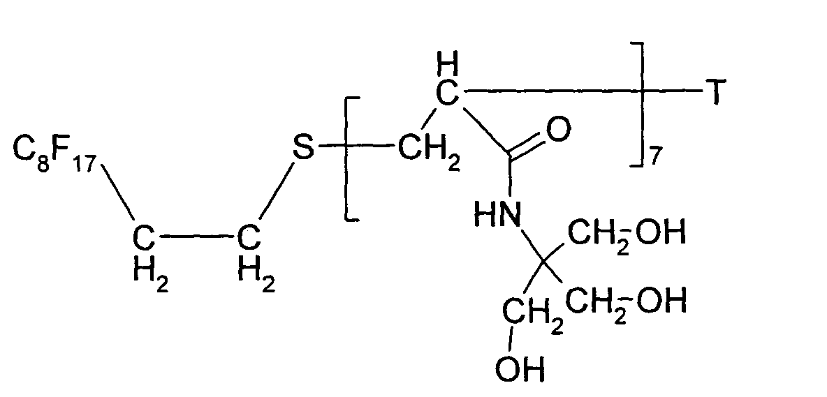
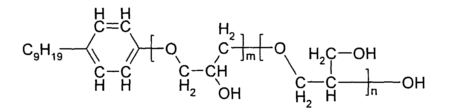
- Three different surfactants were used to demonstrate the effect that surfactants can have on bubble size. The structures of the three surfactants, A, B and C are shown below:
- Rf is a range of fluorocarbon chain lengths based on the general structure CnF2n+1, where typically n possesses the following series of values, 6, 8, 10, 12, and 14.

- where the terminal group "T" is H.
- where m + n = 10 on average
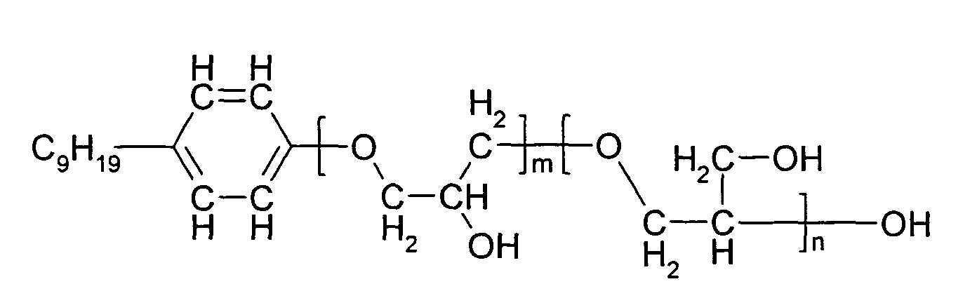
- The scanning electron micrographs shown in Figures 2 to 4 are sections through the resultant materials formed using surfactants Surf A, Surf B and Surf C respectively. The micrographs indicate that Surf A (Fig 2) produces bubbles that are considerably smaller than those produced by Surf B (Fig 3) and Surf C (Fig 4). The scanning electron micrographs are drawn schematically in Figures 5 to 7, corresponding respectively to Figures 2 to 4. In each of Figures 5 to 7 a
support 14 is covered with alayer 16 of foamed polymer. It can be seen that thebubbles 18 are larger in the material formed using Surf B than those in the material formed using Surf A. Similarly, the bubbles in the material formed using Surf C are larger than those in the material formed using Surf A. - Table 1 shows the average bubble size that is achieved when using each of the surfactants.
Surfactant Average Bubble Size (µm) A 5.35 B 11.88 C 14.53 - The bubble size was measured by placing a randomly chosen area of each coating under the light microscope and a micrograph was then taken using image analysis software (Soft Imaging System, SiS). Prior to taking the micrograph, the software was set to the chosen magnification that had previously been accredited using accredited stage micrometer A818. The diameter of ten randomly chosen bubbles was then measured and the average size calculated.
- By measuring the static and dynamic surface tensions of melts containing each surfactant at various concentrations and plotting the results as a function of log(concentration), the logarithms of the critical aggregation concentration and the midpoint of the dynamic surface tension curve can be identified.
- Any suitable method may be used to measure dynamic and static surface tension of liquids. In the present examples, the surface tensions of a range of concentrations of the test surfactant are measured in the trial coating composition under a standard set of conditions at 40°C. The concentration of the surfactant was usually varied from 0.001 to 1 wt% in log concentration intervals of ∼0.5. Higher or intermediate concentrations were sometimes measured as necessary to improve estimates of critical aggregation concentration or the midpoint of the dynamic surface tension curve.
- Both the static surface tension SST and dynamic surface tension DST measurements were made using the Wilhelmy blade method as described by Padday, J F, 2nd Int. Congress of Surface Activity, Butterworths, 1957, 1, 1. The DST measurements were made with an overflowing circular cylinder, having a diameter of 37.5 mm and a liquid overflow rate of ∼9 ml/sec. The data were obtained by raising the surface of the flowing liquid until it just touched the Wilhelmy blade, momentarily dipping the blade by electromechanical means to induce wetting, and taking a final reading 60 seconds later. Other suitable methods of measuring dynamic surface tension would be any technique that offers similar dynamic time scales (surface age) i.e. of the order of 0.05 to 0.25 seconds. Examples include the maximum bubble pressure method and the falling curtain method.
- The SST measurements were not true equilibrium values, but values taken after a defined period. SST values were obtained by, stopping the flow in the dynamic cell, waiting 30 seconds, raising the surface of the liquid until it just touches the Wilhelmy blade, momentarily dipping the blade by electromechanical means to induce wetting, and taking a final reading 60 seconds later, i.e. 90 seconds after stopping the flow.
Claims (14)
- A method of making a material comprising the steps of:coating a support with a solution comprising a polymer, a blowing agent and a surfactant; and,either prior to or after the step of coating said support, interacting with said solution to cause said blowing agent to generate bubbles within the solution causing foaming of the polymer, the surfactant being selected in dependence on whether or not it satisfies one or more predetermined criteria, to control the size of the bubbles.
- A method according to claim 1, in which the one or more criteria include whether or not the critical aggregation concentration of the surfactant is substantially the same as the concentration associated with the midpoint of the dynamic surface tension curve of the surfactant; and,
whether or not the surfactant has a low static surface tension. - A method according to claim 2, in which when both criteria are satisfied, the average bubble size is less than if one or both of the criteria are not satisfied.
- A method according to claim 2, in which one of the criteria is whether or not the surfactant has a static surface tension less than about 28mN/m, preferably less than about 24mN/m.
- A method according to claim 2, in which one of the criteria is whether or not the logarithm of the critical aggregation concentration of the surfactant is within about 0.5 log units, preferably 0.25 log units of the concentration associated with the midpoint of the dynamic surface tension curve of the surfactant
- A method according to claim 1, in which the surfactant iswherein m + n = 10 on average.
- A method according to claim 1, in which the surfactant iswhere the terminal group "T" is H.

- A method according to claim 1, in which the surfactant iswhere Rf is a range of fluorocarbon chain lengths based on the general structure CnF2n+1, where typically n possesses the following series of values, 6, 8, 10, 12, and 14.

- A method according to claim 1, in which the proportion by weight of surfactant to coating solution is from about 0.01% to about 2.0%, preferably from about 0.01 % to about 1.0%.
- A method according to claim 1, in which the surfactant used is a flouro-surfactant.
- A method according to claim 1, in which the polymer is a hydrophilic polymer.
- A method according to claim 11, in which the hydrophilic polymer is selected from the group consisting of polyvinyl alcohol, polyethylene oxide, polyvinylpyrrolidone and gelatin.
- A material formed using the method of claim 1.
- A material according to claim 13, in which the material is an inkjet-recording medium.
Applications Claiming Priority (2)
| Application Number | Priority Date | Filing Date | Title |
|---|---|---|---|
| GB0223835 | 2002-10-12 | ||
| GBGB0223835.0A GB0223835D0 (en) | 2002-10-12 | 2002-10-12 | Method of making a material |
Publications (1)
| Publication Number | Publication Date |
|---|---|
| EP1408072A1 true EP1408072A1 (en) | 2004-04-14 |
Family
ID=9945862
Family Applications (1)
| Application Number | Title | Priority Date | Filing Date |
|---|---|---|---|
| EP20030078204 Withdrawn EP1408072A1 (en) | 2002-10-12 | 2003-10-10 | Method of making a material |
Country Status (4)
| Country | Link |
|---|---|
| US (1) | US6939577B2 (en) |
| EP (1) | EP1408072A1 (en) |
| JP (1) | JP2004137498A (en) |
| GB (1) | GB0223835D0 (en) |
Cited By (2)
| Publication number | Priority date | Publication date | Assignee | Title |
|---|---|---|---|---|
| WO2005075209A1 (en) * | 2004-02-05 | 2005-08-18 | Eastman Kodak Company | Method of making an ink-jet receiver |
| GB2444323A (en) * | 2006-11-30 | 2008-06-04 | Ethicon Inc | Cellular protein sheet material |
Families Citing this family (3)
| Publication number | Priority date | Publication date | Assignee | Title |
|---|---|---|---|---|
| GB0218505D0 (en) * | 2002-08-09 | 2002-09-18 | Eastman Kodak Co | Inkjet recording medium |
| GB0402573D0 (en) * | 2004-02-05 | 2004-03-10 | Eastman Kodak Co | Method of ink-jet printing |
| JP2009084429A (en) * | 2007-09-28 | 2009-04-23 | Fujifilm Corp | Film and manufacturing method thereof |
Citations (5)
| Publication number | Priority date | Publication date | Assignee | Title |
|---|---|---|---|---|
| GB1591292A (en) * | 1976-12-30 | 1981-06-17 | Ciba Geigy Ag | Method of improving fluorinated surfactants |
| EP0474494A2 (en) * | 1990-09-07 | 1992-03-11 | Dai Nippon Printing Co., Ltd. | Thermal transfer image receiving sheet and production process therefor |
| EP0756763A1 (en) * | 1994-04-18 | 1997-02-05 | Finlayson, Dorothy Elizabeth | Antenna arrangement |
| EP0816113A1 (en) * | 1996-06-28 | 1998-01-07 | Dai Nippon Printing Co., Ltd. | Thermal transfer recording method |
| EP0924562A1 (en) * | 1997-12-16 | 1999-06-23 | Eastman Kodak Company | Electrically-conductive overcoat for photographic elements |
Family Cites Families (11)
| Publication number | Priority date | Publication date | Assignee | Title |
|---|---|---|---|---|
| US4089804A (en) * | 1976-12-30 | 1978-05-16 | Ciba-Geigy Corporation | Method of improving fluorinated surfactants |
| US4420434A (en) * | 1981-01-09 | 1983-12-13 | Ciba-Geigy Corporation | Perfluoralkyl anion/perfluoroalkyl cation ion pair complexes |
| CN1197449A (en) * | 1995-08-04 | 1998-10-28 | 韦特科公司 | Reducing estrogenicity of alkoxylated compounds and products thereof |
| JPH09249762A (en) * | 1996-03-14 | 1997-09-22 | Showa Highpolymer Co Ltd | Production of phenol resin foam |
| JPH1110762A (en) * | 1997-06-25 | 1999-01-19 | Oji Paper Co Ltd | Laminated porous sheet and method for producing the same |
| JPH11198525A (en) * | 1997-10-21 | 1999-07-27 | Oji Paper Co Ltd | Sheet for solid ink jet printer and method of manufacturing the same |
| JP2001039024A (en) * | 1999-08-03 | 2001-02-13 | Seiko Epson Corp | Recording medium and method of manufacturing recording medium |
| JP2001079974A (en) * | 1999-09-17 | 2001-03-27 | Olympus Optical Co Ltd | Ink jet printing medium for embossing processed interim material |
| JP3372919B2 (en) * | 1999-12-27 | 2003-02-04 | 山口県 | Seed mat and method for producing the same |
| US20020057323A1 (en) | 2000-06-29 | 2002-05-16 | Yasuo Kurachi | Ink jet recording material |
| JP2002274835A (en) * | 2001-03-21 | 2002-09-25 | Keio Gijuku | Porous silica foam and method for producing the same |
-
2002
- 2002-10-12 GB GBGB0223835.0A patent/GB0223835D0/en not_active Ceased
-
2003
- 2003-10-09 US US10/682,288 patent/US6939577B2/en not_active Expired - Fee Related
- 2003-10-10 EP EP20030078204 patent/EP1408072A1/en not_active Withdrawn
- 2003-10-10 JP JP2003352555A patent/JP2004137498A/en active Pending
Patent Citations (5)
| Publication number | Priority date | Publication date | Assignee | Title |
|---|---|---|---|---|
| GB1591292A (en) * | 1976-12-30 | 1981-06-17 | Ciba Geigy Ag | Method of improving fluorinated surfactants |
| EP0474494A2 (en) * | 1990-09-07 | 1992-03-11 | Dai Nippon Printing Co., Ltd. | Thermal transfer image receiving sheet and production process therefor |
| EP0756763A1 (en) * | 1994-04-18 | 1997-02-05 | Finlayson, Dorothy Elizabeth | Antenna arrangement |
| EP0816113A1 (en) * | 1996-06-28 | 1998-01-07 | Dai Nippon Printing Co., Ltd. | Thermal transfer recording method |
| EP0924562A1 (en) * | 1997-12-16 | 1999-06-23 | Eastman Kodak Company | Electrically-conductive overcoat for photographic elements |
Cited By (3)
| Publication number | Priority date | Publication date | Assignee | Title |
|---|---|---|---|---|
| WO2005075209A1 (en) * | 2004-02-05 | 2005-08-18 | Eastman Kodak Company | Method of making an ink-jet receiver |
| GB2444323A (en) * | 2006-11-30 | 2008-06-04 | Ethicon Inc | Cellular protein sheet material |
| GB2444323B (en) * | 2006-11-30 | 2011-04-06 | Ethicon Inc | Protein sheet material |
Also Published As
| Publication number | Publication date |
|---|---|
| US6939577B2 (en) | 2005-09-06 |
| US20040071901A1 (en) | 2004-04-15 |
| GB0223835D0 (en) | 2002-11-20 |
| JP2004137498A (en) | 2004-05-13 |
Similar Documents
| Publication | Publication Date | Title |
|---|---|---|
| US7582335B2 (en) | Foamed material and a method of making a foamed material | |
| KR101392003B1 (en) | Hollow body made of plastic having a barrier layer on its inner surface and a method for manufacturing the same | |
| DE69109860T2 (en) | LIGHTWEIGHT POLYPROPYLENE FILM AND METHOD FOR THE PRODUCTION THEREOF. | |
| US5618853A (en) | Molded structure comprising a thermoplastic, process for its production and its use | |
| KR101168192B1 (en) | Expanded polypropylene resin beads, method of producing foam molding of expanded polypropylene resin beads and foam molding obtained by the method | |
| JPH03109445A (en) | Synthetic resin extruded foam and its production and 'tatami' floor | |
| US6527993B1 (en) | Method for producing foamed-in-mold product of aromatic polyester based resin | |
| US12011871B2 (en) | Processes for formation of porous biologically compatible scaffold structures | |
| Huang et al. | Polycarbonate hollow fiber membranes by melt extrusion | |
| Paul Handa et al. | Some thermodynamic and kinetic properties of the system PETG‐CO2, and morphological characteristics of the CO2‐blown PETG foams | |
| EP1160274B1 (en) | Pre-expanded particles of crystalline aromatic polyester-based resin, and in-mold expanded product and expanded laminate using the same | |
| EP1408072A1 (en) | Method of making a material | |
| EP0881091B1 (en) | Recording material | |
| Xu et al. | Fundamental study of CBA-blown bubble growth and collapse under atmospheric pressure | |
| TWI868075B (en) | 3d printing system for preparing a three-dimensional object with an autoclave and method for preparing the three-dimensional object in accordance with the 3d printing system | |
| Colton et al. | The nucleation of microcellular thermoplastic foam: Process model and experimental results | |
| KR100955324B1 (en) | Foam of Polyethylene Terephthalate Copolymer and Manufacturing Method Thereof | |
| US7074465B2 (en) | Inkjet recording element comprising polyester ionomer and a method of use | |
| JP2003026137A (en) | Plastic container | |
| Bormashenko et al. | Free‐standing, thermostable, micrometer‐scale honeycomb polymer films and their properties | |
| JP2009221327A (en) | Decomposing foamable compound, foamable composition, foamed article and process for producing foamed article | |
| JP4460098B2 (en) | Polyolefin resin foam sheet and method for producing the same | |
| WO2005075209A1 (en) | Method of making an ink-jet receiver | |
| US7211294B2 (en) | Method of making a material | |
| EP3953037B1 (en) | Liquid guiding boundaries for porous substrates providing increased biodegradability |
Legal Events
| Date | Code | Title | Description |
|---|---|---|---|
| PUAI | Public reference made under article 153(3) epc to a published international application that has entered the european phase |
Free format text: ORIGINAL CODE: 0009012 |
|
| AK | Designated contracting states |
Kind code of ref document: A1 Designated state(s): AT BE BG CH CY CZ DE DK EE ES FI FR GB GR HU IE IT LI LU MC NL PT RO SE SI SK TR |
|
| AX | Request for extension of the european patent |
Extension state: AL LT LV MK |
|
| 17P | Request for examination filed |
Effective date: 20040913 |
|
| AKX | Designation fees paid |
Designated state(s): DE FR GB |
|
| 17Q | First examination report despatched |
Effective date: 20110203 |
|
| STAA | Information on the status of an ep patent application or granted ep patent |
Free format text: STATUS: THE APPLICATION IS DEEMED TO BE WITHDRAWN |
|
| 18D | Application deemed to be withdrawn |
Effective date: 20110614 |