EP1407987A1 - Improved device for conveying objects - Google Patents
Improved device for conveying objects Download PDFInfo
- Publication number
- EP1407987A1 EP1407987A1 EP20030078196 EP03078196A EP1407987A1 EP 1407987 A1 EP1407987 A1 EP 1407987A1 EP 20030078196 EP20030078196 EP 20030078196 EP 03078196 A EP03078196 A EP 03078196A EP 1407987 A1 EP1407987 A1 EP 1407987A1
- Authority
- EP
- European Patent Office
- Prior art keywords
- carrier
- improved device
- shaft
- carriers
- concerned
- Prior art date
- Legal status (The legal status is an assumption and is not a legal conclusion. Google has not performed a legal analysis and makes no representation as to the accuracy of the status listed.)
- Withdrawn
Links
- 239000000969 carrier Substances 0.000 claims abstract description 35
- 239000004809 Teflon Substances 0.000 description 1
- 229920006362 Teflon® Polymers 0.000 description 1
- 239000000463 material Substances 0.000 description 1
Images



Classifications
-
- A—HUMAN NECESSITIES
- A01—AGRICULTURE; FORESTRY; ANIMAL HUSBANDRY; HUNTING; TRAPPING; FISHING
- A01G—HORTICULTURE; CULTIVATION OF VEGETABLES, FLOWERS, RICE, FRUIT, VINES, HOPS OR SEAWEED; FORESTRY; WATERING
- A01G9/00—Cultivation in receptacles, forcing-frames or greenhouses; Edging for beds, lawn or the like
- A01G9/08—Devices for filling-up flower-pots or pots for seedlings; Devices for setting plants or seeds in pots
- A01G9/088—Handling or transferring pots
-
- B—PERFORMING OPERATIONS; TRANSPORTING
- B65—CONVEYING; PACKING; STORING; HANDLING THIN OR FILAMENTARY MATERIAL
- B65G—TRANSPORT OR STORAGE DEVICES, e.g. CONVEYORS FOR LOADING OR TIPPING, SHOP CONVEYOR SYSTEMS OR PNEUMATIC TUBE CONVEYORS
- B65G25/00—Conveyors comprising a cyclically-moving, e.g. reciprocating, carrier or impeller which is disengaged from the load during the return part of its movement
- B65G25/04—Conveyors comprising a cyclically-moving, e.g. reciprocating, carrier or impeller which is disengaged from the load during the return part of its movement the carrier or impeller having identical forward and return paths of movement, e.g. reciprocating conveyors
- B65G25/08—Conveyors comprising a cyclically-moving, e.g. reciprocating, carrier or impeller which is disengaged from the load during the return part of its movement the carrier or impeller having identical forward and return paths of movement, e.g. reciprocating conveyors having impellers, e.g. pushers
- B65G25/10—Conveyors comprising a cyclically-moving, e.g. reciprocating, carrier or impeller which is disengaged from the load during the return part of its movement the carrier or impeller having identical forward and return paths of movement, e.g. reciprocating conveyors having impellers, e.g. pushers with impeller pivotally mounted on a reciprocating bar
Definitions
- the present invention concerns an improved device for conveying objects, such as boxes, tins, dishes or the like.
- the invention in particular concerns a device of the type which mainly consists of one or several guides upon which the objects to be conveyed are provided such that they can be moved; one or several U-shaped struts directed according to the conveying direction extending under the objects to be conveyed and which can be moved to and fro in their longitudinal direction; and finally carriers provided at a distance from each other between the flanges of the aforesaid struts and which are provided with a shaft which is bearing-mounted with its far ends on either side of the carrier in two opposite passages in the flanges of the strut concerned, whereby the part of the carrier on one side of the aforesaid shaft is heavier than the part on the other side of the shaft, and whereby this heavier part, when the carrier is in rest position, rests on the bottom of the U-shaped strut concerned, while the lighter part protrudes from the strut with its free end in this position.
- An advantage of such a relatively large number of passages is that the carriers, as a function of the requirements, for example as a function of the dimensions of the objects to be moved or as a function of the desired in-between distance between the objects to be moved, can be provided in the struts with a larger or smaller in-between distance.
- the aforesaid carriers are provided in the struts by means of through-feed shafts which run through two opposite passages at every so many passages and which are kept in place by means of nuts and washers provided on a threaded part at the far ends of these through-feed shafts.
- a first disadvantage of such known devices is that applying the carriers is very time-consuming.
- Another disadvantage is that tools are required to apply and/or move the carriers.
- Yet another disadvantage is that it is not excluded for the nuts, washers and through-feed shafts to fall on the floor and get lost when being dismounted in order to adjust the device.
- the present invention aims to remedy these and other disadvantages.
- the invention concerns an improved device of the aforesaid type, whereby the aforesaid passages are connected to the free edges of the flanges concerned of the U-shaped strut by means of grooves, and whereby the free ends of the aforesaid shaft of every carrier have a diameter which is somewhat smaller than the diameter of an aforesaid passage.
- An advantage of such a device according to the invention is that the place of the carriers in the U-shaped strut can be adjusted in a very simple and fast manner by simply taking the carriers with the far ends of their shafts out of the struts via the aforesaid grooves and by putting them back in the opposite sense in another place in the strut concerned.
- Another advantage is that, in order to move the carriers, no extra tools are required and that no parts such as nuts and washers have to be dismounted, so that there is not any danger for such loose parts to get lost while adjusting the device.
- Such a transport device can be used for conveying all sorts of objects, but it is particularly suitable for conveying pot plants which are placed with several pots next to one another in dishes in nurseries or the like which are systematically moved from the starting point of the conveyor line to the end of the conveyor line as the plants grow.
- Figures 1 to 12 represent an improved device according to the invention for conveying objects, for example dishes 1 in which pot plants 2 are placed next to each other.
- This device mainly consists of a frame 3 upon which are provided two parallel guides 4 extending in the conveying direction, represented by arrow T, and which in this case are formed of two tubular beams onto which is fixed a slide strip, made of Teflon or the like, on the top side.
- U-shaped struts 5 are connected to each other by means of cross connections 10 and they are coupled to common drive means 11 known as such, which allow the struts 5 to move to and fro in their longitudinal direction.
- Each of the passages 12 is connected to the free edge 8 of the flange 9 concerned according to the invention by means of a continuous groove 13 having a width A which is smaller than the diameter B of the passages 12.
- carriers 14 are provided between the flanges 9 of the struts 5 which in this case have a predominantly wedge-shaped body with a top end 15 and a lower end 16 directed to the beginning 17 of the device.
- the carriers 14 are each provided with a horizontal shaft which is in this case formed in one piece with the body of the carrier 14 concerned and which is formed of protruding journals 18 which are bearing-mounted in two passages 12 situated opposite to each other in the flanges 9 of the U-shaped strut 5 concerned.
- the aforesaid journals 18 have a diameter which is somewhat smaller than the diameter of a passage 12 and which are provided with two parallel sides 19 situated opposite to each other whereby the distance C of these sides 19 is equal to or somewhat smaller than the width A of the grooves 13.
- the shape and dimensions of the carriers 14 are such that the part of the carriers 14 on one side of the shaft, namely on the far end 16, is heavier than the part on the other side of the shaft, such that each carrier 14, as represented in figure 4, automatically assumes an inclined position when in rest, whereby the heavier far end 16 rests on the back 6 of the strut 5 concerned, while the far end 15 protrudes above the strut 5 and above the guides 4, whereby the sides 19 of the journals 18 are parallel to the back 6 of the struts 5 in this position, are perpendicular to the longitudinal direction of the grooves 13 respectively.
- the working of the device 1 is very simple and is represented step by step by means of figures 7 to 10.
- a dish 1 with pot plants 2 to be conveyed is loaded at the starting point 17 of the device, diagonally to the guides 4, as represented in figures 1 and 7.
- the carriers 14, as represented in figures 8 and 9, can move freely under a dish 1, whereby the carriers 14 can tilt counter clockwise in an unhindered manner in this case, as the journals 18 rotate in the corresponding passages 12.
- the dish 1 is thus moved step by step from the starting point 17 of the device to the far end of this device.
- Figures 11 and 12 show that a carrier 14 according to the invention can be very easily taken out of the struts 5 without any tools, can be provided in it again respectively.
- the carriers 14 are tilted to this end until the levelled sides 19 of the journals 18 of the shaft of the carrier 14 concerned are situated in the extension of the grooves 13, after which the carrier 14 can be lifted out of the passages 12 and grooves 13 in the vertical direction.
- the sides 19 of the journals 18 are preferably oriented such that they are parallel to the longitudinal direction of the grooves 13 when the carrier 14 concerned has tilted such that it lies against the back 6 of the strut 5 concerned with its far end 15, whereby the carrier 14 can be removed from the strut 5 in the aforesaid simple manner.
- the position of the carrier 14 which corresponds to figures 11 and 12 is a position which does not occur when the device is used in a normal manner, such that, since the carrier 14 can only be taken out of the strut in this position, it is prevented from being accidentally pushed out of the strut 5 during use.
- a carrier 14 can also be placed back in a strut 5 very quickly and without any tools in the opposite sense, for example at another location, in order to account for the different shapes and dimensions of a new series of dishes 1 to be conveyed or for another required distance between the dishes 1 or, in the opposite position, to convey the dishes 1 in a direction opposite to the one described above.
- the shaft of the carriers 14 must not necessarily be made in one piece and out of the same material as the body of the carriers 14, but that this shaft can for example also be realised by providing a separate shaft in the body of the carrier 14 such that it cannot rotate or by means of two separate coaxial journals 18 to be fixed in any way whatsoever on either side of the carrier 14.
Landscapes
- Life Sciences & Earth Sciences (AREA)
- Environmental Sciences (AREA)
- Non-Mechanical Conveyors (AREA)
- Specific Conveyance Elements (AREA)
Abstract
Description
- The present invention concerns an improved device for conveying objects, such as boxes, tins, dishes or the like.
- The invention in particular concerns a device of the type which mainly consists of one or several guides upon which the objects to be conveyed are provided such that they can be moved; one or several U-shaped struts directed according to the conveying direction extending under the objects to be conveyed and which can be moved to and fro in their longitudinal direction; and finally carriers provided at a distance from each other between the flanges of the aforesaid struts and which are provided with a shaft which is bearing-mounted with its far ends on either side of the carrier in two opposite passages in the flanges of the strut concerned, whereby the part of the carrier on one side of the aforesaid shaft is heavier than the part on the other side of the shaft, and whereby this heavier part, when the carrier is in rest position, rests on the bottom of the U-shaped strut concerned, while the lighter part protrudes from the strut with its free end in this position.
- It is known that with such known embodiments, when the U-shaped struts make a to movement in the conveying direction, the objects to be moved are carried along in the conveying direction by the carriers, while in the fro movement, in the opposite direction of the conveyance, the carriers can pass freely under the objects to be moved without thereby moving the objects, such that as a result of consecutive to and fro movements, the objects to be conveyed will be gradually moved to the far end of the device.
- It is known that the aforesaid flanges of the U-shaped struts in which the carriers are provided are usually equipped with a relatively large number of passages which are provided opposite to each other in pairs and which are situated at short, equal distances between them.
- An advantage of such a relatively large number of passages is that the carriers, as a function of the requirements, for example as a function of the dimensions of the objects to be moved or as a function of the desired in-between distance between the objects to be moved, can be provided in the struts with a larger or smaller in-between distance.
- It is also known that the aforesaid carriers are provided in the struts by means of through-feed shafts which run through two opposite passages at every so many passages and which are kept in place by means of nuts and washers provided on a threaded part at the far ends of these through-feed shafts.
- A first disadvantage of such known devices is that applying the carriers is very time-consuming.
- Another disadvantage of such known devices is that moving the carriers in the U-shaped struts is very time-consuming as well, since the aforesaid nuts and through-feed shafts have to be dismounted first and since, subsequently, after the carriers have been moved, they also have to be put back and be fixed.
- Another disadvantage is that tools are required to apply and/or move the carriers.
- Yet another disadvantage is that it is not excluded for the nuts, washers and through-feed shafts to fall on the floor and get lost when being dismounted in order to adjust the device.
- An additional disadvantage is that the nuts of the through-feed shafts can become detached due to vibrations of the to and fro movements, as a result of which the through-feed shafts may fall out of the carriers and the carriers concerned are consequently put out of order, so that objects can get stuck in this place and the conveyance of the objects can become obstructed.
- The present invention aims to remedy these and other disadvantages.
- To this end, the invention concerns an improved device of the aforesaid type, whereby the aforesaid passages are connected to the free edges of the flanges concerned of the U-shaped strut by means of grooves, and whereby the free ends of the aforesaid shaft of every carrier have a diameter which is somewhat smaller than the diameter of an aforesaid passage.
- An advantage of such a device according to the invention is that the place of the carriers in the U-shaped strut can be adjusted in a very simple and fast manner by simply taking the carriers with the far ends of their shafts out of the struts via the aforesaid grooves and by putting them back in the opposite sense in another place in the strut concerned.
- Another advantage is that, in order to move the carriers, no extra tools are required and that no parts such as nuts and washers have to be dismounted, so that there is not any danger for such loose parts to get lost while adjusting the device.
- Also when one wishes to reverse the carriers in order to move the objects in the opposite sense, this can be done in the same fast manner without using any tools.
- Such a transport device according to the invention can be used for conveying all sorts of objects, but it is particularly suitable for conveying pot plants which are placed with several pots next to one another in dishes in nurseries or the like which are systematically moved from the starting point of the conveyor line to the end of the conveyor line as the plants grow.
- Given the large variety of dishes which are used in such nurseries and the required in-between distances between these dishes, it is indeed important that the carriers in this application can be positioned quickly and smoothly.
- In order to better explain the characteristics of the invention, the following preferred embodiment of an improved device according to the invention for conveying objects is described as an example only without being limitative in any way, with reference to the accompanying drawings, in which:
- figure 1 schematically represents an improved device according to the invention for conveying objects, in particular dishes with plants, in perspective;
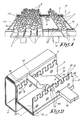
- figure 2 represents the part indicated by F2 in figure 1 to a larger scale;
- figure 3 is an exploded view of the part represented in figure 2;
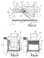
- figure 4 represents a section according to line IV-IV in figure 2;
- figure 5 represents a section according to line V-V in figure 4;
- figure 6 represents a section according to line VI-VI in figure 4;
- figures 7 to 10 represent views as in figure 4, but for various successive positions during the use of the improved device for conveying objects;
- figures 11 and 12 represent views as in figure 4, but for two other positions.
-
- Figures 1 to 12 represent an improved device according to the invention for conveying objects, for
example dishes 1 in whichpot plants 2 are placed next to each other. - This device mainly consists of a frame 3 upon which are provided two
parallel guides 4 extending in the conveying direction, represented by arrow T, and which in this case are formed of two tubular beams onto which is fixed a slide strip, made of Teflon or the like, on the top side. - Between the
aforesaid guides 4 are provided, parallel thereto, twoU-shaped struts 5 which are provided with theirback 6 in aguide 7 in the given example, such that they can slide, for example in the shape of a groove or the like fixed to the frame 3 or to anaforesaid guide 4, in such a manner that thefree edges 8 of theflanges 9 of theU-shaped struts 5 are situated lower than the top side of theguides 4. - The
aforesaid U-shaped struts 5 are connected to each other by means ofcross connections 10 and they are coupled to common drive means 11 known as such, which allow thestruts 5 to move to and fro in their longitudinal direction. - In the
flanges 9 of thestruts 5, at a fixed distance from thefree edges 8, are provided identicalcircular passages 12 situated in pairs opposite to each other and which are situated at regular distances from each other. - Each of the
passages 12 is connected to thefree edge 8 of theflange 9 concerned according to the invention by means of acontinuous groove 13 having a width A which is smaller than the diameter B of thepassages 12. - Between the
flanges 9 of thestruts 5 are providedcarriers 14 at regular distances from each other which in this case have a predominantly wedge-shaped body with atop end 15 and alower end 16 directed to thebeginning 17 of the device. - The
carriers 14 are each provided with a horizontal shaft which is in this case formed in one piece with the body of thecarrier 14 concerned and which is formed of protrudingjournals 18 which are bearing-mounted in twopassages 12 situated opposite to each other in theflanges 9 of theU-shaped strut 5 concerned. - In the given example, the
aforesaid journals 18 have a diameter which is somewhat smaller than the diameter of apassage 12 and which are provided with twoparallel sides 19 situated opposite to each other whereby the distance C of thesesides 19 is equal to or somewhat smaller than the width A of thegrooves 13. - The shape and dimensions of the
carriers 14 are such that the part of thecarriers 14 on one side of the shaft, namely on thefar end 16, is heavier than the part on the other side of the shaft, such that eachcarrier 14, as represented in figure 4, automatically assumes an inclined position when in rest, whereby the heavierfar end 16 rests on theback 6 of thestrut 5 concerned, while the farend 15 protrudes above thestrut 5 and above theguides 4, whereby thesides 19 of thejournals 18 are parallel to theback 6 of thestruts 5 in this position, are perpendicular to the longitudinal direction of thegrooves 13 respectively. - The working of the
device 1 is very simple and is represented step by step by means of figures 7 to 10. - A
dish 1 withpot plants 2 to be conveyed is loaded at thestarting point 17 of the device, diagonally to theguides 4, as represented in figures 1 and 7. - When the drive means 11 are excited, the
U-shaped struts 5, together with thecarriers 14 provided therein, are moved to and fro in their longitudinal direction. - When there is a movement in the sense of arrow W in figure 7, in particular in the opposite sense of the conveying direction T, the
carriers 14, as represented in figures 8 and 9, can move freely under adish 1, whereby thecarriers 14 can tilt counter clockwise in an unhindered manner in this case, as thejournals 18 rotate in thecorresponding passages 12. - Once the
carriers 14 have gone past thedish 1, they automatically turn back to their rest position, as represented in figure 10, whereby the far ends 15 protrude above theguides 4 again. - In the case of a movement according to the conveying direction T, as represented in figure 10, the far
end 15 of thecarriers 14 makes contact with theside wall 20 of adish 1 turned towards the starting point of the device, and thedish 1, as thecarriers 14 cannot tilt clockwise as of their rest position, will be carried along in the conveying direction T by thecarriers 14 until the movement of thestruts 5 is reversed again and the carriers can again freely move under thedish 1. - Thanks to successive to and fro movements of the
struts 5, thedish 1 is thus moved step by step from thestarting point 17 of the device to the far end of this device. - Figures 11 and 12 show that a
carrier 14 according to the invention can be very easily taken out of thestruts 5 without any tools, can be provided in it again respectively. - The
carriers 14 are tilted to this end until the levelledsides 19 of thejournals 18 of the shaft of thecarrier 14 concerned are situated in the extension of thegrooves 13, after which thecarrier 14 can be lifted out of thepassages 12 andgrooves 13 in the vertical direction. - The
sides 19 of thejournals 18 are preferably oriented such that they are parallel to the longitudinal direction of thegrooves 13 when thecarrier 14 concerned has tilted such that it lies against theback 6 of thestrut 5 concerned with itsfar end 15, whereby thecarrier 14 can be removed from thestrut 5 in the aforesaid simple manner. It is clear that the position of thecarrier 14 which corresponds to figures 11 and 12 is a position which does not occur when the device is used in a normal manner, such that, since thecarrier 14 can only be taken out of the strut in this position, it is prevented from being accidentally pushed out of thestrut 5 during use. - From what precedes follows that a
carrier 14 can also be placed back in astrut 5 very quickly and without any tools in the opposite sense, for example at another location, in order to account for the different shapes and dimensions of a new series ofdishes 1 to be conveyed or for another required distance between thedishes 1 or, in the opposite position, to convey thedishes 1 in a direction opposite to the one described above. - It is clear that the shaft of the
carriers 14 must not necessarily be made in one piece and out of the same material as the body of thecarriers 14, but that this shaft can for example also be realised by providing a separate shaft in the body of thecarrier 14 such that it cannot rotate or by means of two separatecoaxial journals 18 to be fixed in any way whatsoever on either side of thecarrier 14. - The invention is by no means limited to the above-described embodiments given as an example and represented in the accompanying drawings; on the contrary, such an improved device for conveying objects according to the invention can be made in all sorts of shapes and dimensions while still remaining within the scope of the invention.
Claims (8)
- Improved device for conveying objects which mainly consists of one or several guides (4) upon which the objects to be conveyed are provided such that they can be moved; one or several U-shaped struts (5) directed according to the conveying direction (T) extending under the objects to be conveyed and which can be moved to and fro in their longitudinal direction; and finally carriers (14) provided at a distance from each other between the flanges (9) of the aforesaid struts (5) and which are provided with a shaft which is bearing-mounted with its far ends (18) on either side of the carrier (14) in two opposite passages (12) in the flanges (9) of the strut (5) concerned, whereby the part of the carrier (14) on one side of the aforesaid shaft is heavier than the part on the other side of the shaft, and whereby this heavier part, when the carrier (14) is in rest position, rests on the back (6) of the U-shaped strut (5) concerned, while the lighter part protrudes with its free end (15) from the strut (5) in this position, characterised in that the above-mentioned passages (12) are connected to the free edges (8) of the flanges (9) concerned of the U-shaped strut (5) by means of grooves (13), and in that the journals (18) of the above-mentioned shaft of every carrier (14) has a diameter which is somewhat smaller than the diameter of an aforesaid passage (12).
- Improved device according to claim 1, characterised in that the grooves (13) are perpendicular to the free edge (8) of the flange (9) concerned of the U-shaped strut (5).
- Improved device according to claim 1 or 2, characterised in that the passages (12) are circular.
- Improved device according to claim 3, characterised in that the grooves (13) have a width (A) which is smaller than the diameter (B) of the passages (12) .
- Improved device according to claim 4, characterised in that the journals (18) of the above-mentioned shafts of the carriers (14) have two parallel sides (19) situated at a distance (C) from each other which is somewhat smaller than the width (A) of the grooves (13) .
- Improved device according to claim 5, characterised in that the above-mentioned sides (19) of the journals (18) of a shaft of a carrier (14) are parallel to the back (6) of the strut (5) when the carrier (14) is in rest position.
- Improved device according to claim 5, characterised in that the above-mentioned sides (19) of the journals (18) of a shaft of a carrier (14) are parallel to the longitudinal direction of the grooves (13) when the carrier (14) has been tilted such that it rests with one far end (15) on the back (6) of the U-shaped strut (5) concerned.
- Improved device according to any of the preceding claims, characterised in that the shaft of a carrier (14) is made in one piece with or as separate of the body of the carrier (14), such that it cannot rotate.
Applications Claiming Priority (2)
| Application Number | Priority Date | Filing Date | Title |
|---|---|---|---|
| BE2002/0585A BE1015138A4 (en) | 2002-10-11 | 2002-10-11 | Improved device for transport of voorpwerpen. |
| BE200200585 | 2002-10-11 |
Publications (1)
| Publication Number | Publication Date |
|---|---|
| EP1407987A1 true EP1407987A1 (en) | 2004-04-14 |
Family
ID=32000005
Family Applications (1)
| Application Number | Title | Priority Date | Filing Date |
|---|---|---|---|
| EP20030078196 Withdrawn EP1407987A1 (en) | 2002-10-11 | 2003-10-09 | Improved device for conveying objects |
Country Status (2)
| Country | Link |
|---|---|
| EP (1) | EP1407987A1 (en) |
| BE (1) | BE1015138A4 (en) |
Cited By (16)
| Publication number | Priority date | Publication date | Assignee | Title |
|---|---|---|---|---|
| WO2010138027A1 (en) | 2009-05-27 | 2010-12-02 | Plantagon International Ab | Conveying system, tower structure with conveying system, and method for conveying containers with a conveying system |
| CN106219168A (en) * | 2016-08-30 | 2016-12-14 | 山东钢铁股份有限公司 | A kind of reciprocating poking device |
| USD821194S1 (en) | 2017-03-10 | 2018-06-26 | Johannes Cornelious VAN WINGERDEN | Produce bowl |
| US10004187B1 (en) | 2017-07-26 | 2018-06-26 | Johannes Cornelious VAN WINGERDEN | Hydroponic growing system |
| US10051799B1 (en) | 2017-07-26 | 2018-08-21 | Johannes Cornelious VAN WINGERDEN | Gutter for a hydroponic growing system |
| US10080335B1 (en) | 2017-10-02 | 2018-09-25 | Johannes Cornelious VAN WINGERDEN | Apparatus, system and method for a grow ring for produce |
| USD830664S1 (en) | 2017-03-30 | 2018-10-09 | Johannes Cornelious VAN WINGERDEN | Engagement device for a hydroponic growing system |
| USD831178S1 (en) | 2017-05-12 | 2018-10-16 | Johannes Cornelious VAN WINGERDEN | Gutter |
| US20190029199A1 (en) * | 2017-07-26 | 2019-01-31 | Johannes Cornelious VAN WINGERDEN | Hydroponic growing system |
| USD839783S1 (en) | 2017-04-27 | 2019-02-05 | Johannes Cornelious VAN WINGERDEN | Growing trough |
| US10201134B1 (en) | 2017-07-26 | 2019-02-12 | Johannes Cornelious VAN WINGERDEN | Hydroponic growing system |
| US10368507B2 (en) | 2017-07-26 | 2019-08-06 | Johannes Cornelious VAN WINGERDEN | Hydroponic growing system |
| US20230225258A1 (en) * | 2020-06-24 | 2023-07-20 | Mjnn Llc | Indexing plants in two-dimensional and three-dimensional space in a controlled growing environment |
| US12171175B2 (en) | 2018-12-21 | 2024-12-24 | Mjnn Llc | Indexing plants in two-dimensional and three-dimensional space in a controlled growing environment |
| FI131244B1 (en) * | 2022-12-02 | 2025-01-07 | Sba Interior Oy | A feeding device and a farming arrangement |
| US12356898B2 (en) * | 2021-01-08 | 2025-07-15 | Gyeongnyeong LEE | Plant cultivation system |
Citations (6)
| Publication number | Priority date | Publication date | Assignee | Title |
|---|---|---|---|---|
| DE271699C (en) * | ||||
| US3090481A (en) * | 1959-08-17 | 1963-05-21 | Hans Sickinger | Conveying mechanism and feed member therefor |
| US3826349A (en) * | 1970-05-06 | 1974-07-30 | C Stevenson | Live storage conveyor system |
| US4476973A (en) * | 1982-04-01 | 1984-10-16 | Pack-All, Inc. | Automatic reciprocal feed mechanism |
| DE3502558A1 (en) * | 1985-01-25 | 1986-07-31 | Otto Dipl.-Ing. 4700 Hamm Schulze-Berge | Roller conveyor |
| JP2002120925A (en) * | 2000-10-16 | 2002-04-23 | Mitsubishi Heavy Ind Ltd | Article moving device |
-
2002
- 2002-10-11 BE BE2002/0585A patent/BE1015138A4/en not_active IP Right Cessation
-
2003
- 2003-10-09 EP EP20030078196 patent/EP1407987A1/en not_active Withdrawn
Patent Citations (6)
| Publication number | Priority date | Publication date | Assignee | Title |
|---|---|---|---|---|
| DE271699C (en) * | ||||
| US3090481A (en) * | 1959-08-17 | 1963-05-21 | Hans Sickinger | Conveying mechanism and feed member therefor |
| US3826349A (en) * | 1970-05-06 | 1974-07-30 | C Stevenson | Live storage conveyor system |
| US4476973A (en) * | 1982-04-01 | 1984-10-16 | Pack-All, Inc. | Automatic reciprocal feed mechanism |
| DE3502558A1 (en) * | 1985-01-25 | 1986-07-31 | Otto Dipl.-Ing. 4700 Hamm Schulze-Berge | Roller conveyor |
| JP2002120925A (en) * | 2000-10-16 | 2002-04-23 | Mitsubishi Heavy Ind Ltd | Article moving device |
Cited By (21)
| Publication number | Priority date | Publication date | Assignee | Title |
|---|---|---|---|---|
| CN102448856A (en) * | 2009-05-27 | 2012-05-09 | 布兰塔根国际公司 | Tower structure, and method for conveying containers with a conveying system |
| US9004268B2 (en) | 2009-05-27 | 2015-04-14 | Plantagon International Ab | Conveying system, tower structure with conveying system, and method for conveying containers with a conveying system |
| WO2010138027A1 (en) | 2009-05-27 | 2010-12-02 | Plantagon International Ab | Conveying system, tower structure with conveying system, and method for conveying containers with a conveying system |
| CN106219168A (en) * | 2016-08-30 | 2016-12-14 | 山东钢铁股份有限公司 | A kind of reciprocating poking device |
| USD821194S1 (en) | 2017-03-10 | 2018-06-26 | Johannes Cornelious VAN WINGERDEN | Produce bowl |
| USD845758S1 (en) | 2017-03-10 | 2019-04-16 | Johannes Cornelious VAN WINGERDEN | Produce bowl |
| USD830664S1 (en) | 2017-03-30 | 2018-10-09 | Johannes Cornelious VAN WINGERDEN | Engagement device for a hydroponic growing system |
| USD839783S1 (en) | 2017-04-27 | 2019-02-05 | Johannes Cornelious VAN WINGERDEN | Growing trough |
| USD831178S1 (en) | 2017-05-12 | 2018-10-16 | Johannes Cornelious VAN WINGERDEN | Gutter |
| US20190029199A1 (en) * | 2017-07-26 | 2019-01-31 | Johannes Cornelious VAN WINGERDEN | Hydroponic growing system |
| US10051799B1 (en) | 2017-07-26 | 2018-08-21 | Johannes Cornelious VAN WINGERDEN | Gutter for a hydroponic growing system |
| US10201134B1 (en) | 2017-07-26 | 2019-02-12 | Johannes Cornelious VAN WINGERDEN | Hydroponic growing system |
| US10004187B1 (en) | 2017-07-26 | 2018-06-26 | Johannes Cornelious VAN WINGERDEN | Hydroponic growing system |
| US10368507B2 (en) | 2017-07-26 | 2019-08-06 | Johannes Cornelious VAN WINGERDEN | Hydroponic growing system |
| US10485192B2 (en) * | 2017-07-26 | 2019-11-26 | Johannes Cornelious VAN WINGERDEN | Hydroponic growing system |
| US10080335B1 (en) | 2017-10-02 | 2018-09-25 | Johannes Cornelious VAN WINGERDEN | Apparatus, system and method for a grow ring for produce |
| US12171175B2 (en) | 2018-12-21 | 2024-12-24 | Mjnn Llc | Indexing plants in two-dimensional and three-dimensional space in a controlled growing environment |
| US20230225258A1 (en) * | 2020-06-24 | 2023-07-20 | Mjnn Llc | Indexing plants in two-dimensional and three-dimensional space in a controlled growing environment |
| US12268137B2 (en) * | 2020-06-24 | 2025-04-08 | Mjnn Llc | Indexing plants in two-dimensional and three-dimensional space in a controlled growing environment |
| US12356898B2 (en) * | 2021-01-08 | 2025-07-15 | Gyeongnyeong LEE | Plant cultivation system |
| FI131244B1 (en) * | 2022-12-02 | 2025-01-07 | Sba Interior Oy | A feeding device and a farming arrangement |
Also Published As
| Publication number | Publication date |
|---|---|
| BE1015138A4 (en) | 2004-10-05 |
Similar Documents
| Publication | Publication Date | Title |
|---|---|---|
| US5004097A (en) | Replaceable snap-on modular overlay for rod and link turn-curve conveyor belts | |
| BE1015138A4 (en) | Improved device for transport of voorpwerpen. | |
| DE102011018983A1 (en) | Picking system for use with picking area for manual picking of articles from source containers in target container, has multiple tray conveyors that are provided for target container and source container | |
| EP1432627B1 (en) | Commissioning device | |
| DE69116169T2 (en) | HYGIENIC CONVEYOR WITH FLEXIBLE BELT | |
| US3179138A (en) | Mushroom trimmer | |
| WO1999018014A3 (en) | Automatic commissioning machine for automatically commissioning items located on shelves | |
| EP2899000A1 (en) | Cutting device for cutting vegetables, in particular cutting off ends of elongated vegetables | |
| DE19714455A1 (en) | Method and device for automatic order picking | |
| EP0323965A1 (en) | CONVEYOR. | |
| EP1167248A1 (en) | Conveyor | |
| US6883659B2 (en) | Conveyor transfer assembly | |
| JPH0343161B2 (en) | ||
| EP2163491B1 (en) | Warehouse robot | |
| DE102004059809B4 (en) | Method and device for loading and unloading of stored goods from shelves of a storage rack | |
| US4143753A (en) | Conveying arrangement | |
| DE3206083A1 (en) | Vertical conveyor serving for transporting articles from one plane to another plane | |
| EP0009476B1 (en) | Device for stacking plate-shaped articles | |
| JP5009578B2 (en) | Sorting device | |
| DE2744879C3 (en) | Device for tablet synchronization in a crockery clearing system | |
| DE2532410A1 (en) | Food tray stacking mechanism - works vertically with paternoster type conveyor in conjunction with horizontal feed conveyor | |
| EP1488687B1 (en) | Plant pot support | |
| DE102015113400A1 (en) | Food conveying and dispensing device | |
| DE19623002A1 (en) | Garments conveying circuit for classification | |
| WO2007008089A1 (en) | Continuous processing apparatus |
Legal Events
| Date | Code | Title | Description |
|---|---|---|---|
| PUAI | Public reference made under article 153(3) epc to a published international application that has entered the european phase |
Free format text: ORIGINAL CODE: 0009012 |
|
| AK | Designated contracting states |
Kind code of ref document: A1 Designated state(s): AT BE BG CH CY CZ DE DK EE ES FI FR GB GR HU IE IT LI LU MC NL PT RO SE SI SK TR |
|
| AX | Request for extension of the european patent |
Extension state: AL LT LV MK |
|
| 17P | Request for examination filed |
Effective date: 20040427 |
|
| AKX | Designation fees paid |
Designated state(s): AT BE BG CH CY CZ DE DK EE ES FI FR GB GR HU IE IT LI LU MC NL PT RO SE SI SK TR |
|
| 17Q | First examination report despatched |
Effective date: 20050307 |
|
| GRAP | Despatch of communication of intention to grant a patent |
Free format text: ORIGINAL CODE: EPIDOSNIGR1 |
|
| STAA | Information on the status of an ep patent application or granted ep patent |
Free format text: STATUS: THE APPLICATION IS DEEMED TO BE WITHDRAWN |
|
| 18D | Application deemed to be withdrawn |
Effective date: 20051109 |