EP1407801A2 - Elektromedizinisches Implantat zur interkardialen Herztherapie - Google Patents
Elektromedizinisches Implantat zur interkardialen Herztherapie Download PDFInfo
- Publication number
- EP1407801A2 EP1407801A2 EP03090334A EP03090334A EP1407801A2 EP 1407801 A2 EP1407801 A2 EP 1407801A2 EP 03090334 A EP03090334 A EP 03090334A EP 03090334 A EP03090334 A EP 03090334A EP 1407801 A2 EP1407801 A2 EP 1407801A2
- Authority
- EP
- European Patent Office
- Prior art keywords
- battery
- circuit
- housing
- implant
- implant according
- Prior art date
- Legal status (The legal status is an assumption and is not a legal conclusion. Google has not performed a legal analysis and makes no representation as to the accuracy of the status listed.)
- Granted
Links
- 239000007943 implant Substances 0.000 title claims abstract description 92
- 238000002560 therapeutic procedure Methods 0.000 title 1
- 230000008961 swelling Effects 0.000 claims description 6
- 239000003792 electrolyte Substances 0.000 claims description 5
- 229940030602 cardiac therapy drug Drugs 0.000 claims description 4
- RTAQQCXQSZGOHL-UHFFFAOYSA-N Titanium Chemical compound [Ti] RTAQQCXQSZGOHL-UHFFFAOYSA-N 0.000 claims description 2
- 239000010936 titanium Substances 0.000 claims description 2
- 229910052719 titanium Inorganic materials 0.000 claims description 2
- 239000000560 biocompatible material Substances 0.000 claims 1
- 238000004519 manufacturing process Methods 0.000 description 11
- 238000000034 method Methods 0.000 description 9
- 230000008569 process Effects 0.000 description 7
- 238000009434 installation Methods 0.000 description 4
- 239000003990 capacitor Substances 0.000 description 3
- 230000008859 change Effects 0.000 description 3
- 238000013461 design Methods 0.000 description 3
- WHXSMMKQMYFTQS-UHFFFAOYSA-N Lithium Chemical compound [Li] WHXSMMKQMYFTQS-UHFFFAOYSA-N 0.000 description 2
- 238000010276 construction Methods 0.000 description 2
- 238000003487 electrochemical reaction Methods 0.000 description 2
- 238000005516 engineering process Methods 0.000 description 2
- 230000006870 function Effects 0.000 description 2
- AMWRITDGCCNYAT-UHFFFAOYSA-L hydroxy(oxo)manganese;manganese Chemical compound [Mn].O[Mn]=O.O[Mn]=O AMWRITDGCCNYAT-UHFFFAOYSA-L 0.000 description 2
- 238000007654 immersion Methods 0.000 description 2
- 229910001947 lithium oxide Inorganic materials 0.000 description 2
- NUJOXMJBOLGQSY-UHFFFAOYSA-N manganese dioxide Chemical compound O=[Mn]=O NUJOXMJBOLGQSY-UHFFFAOYSA-N 0.000 description 2
- 239000000463 material Substances 0.000 description 2
- 229920005989 resin Polymers 0.000 description 2
- 239000011347 resin Substances 0.000 description 2
- 239000000758 substrate Substances 0.000 description 2
- RYGMFSIKBFXOCR-UHFFFAOYSA-N Copper Chemical group [Cu] RYGMFSIKBFXOCR-UHFFFAOYSA-N 0.000 description 1
- 241000587161 Gomphocarpus Species 0.000 description 1
- 230000004913 activation Effects 0.000 description 1
- 238000004026 adhesive bonding Methods 0.000 description 1
- 238000013459 approach Methods 0.000 description 1
- 206010003119 arrhythmia Diseases 0.000 description 1
- 230000001746 atrial effect Effects 0.000 description 1
- 230000008901 benefit Effects 0.000 description 1
- 230000000747 cardiac effect Effects 0.000 description 1
- 239000000969 carrier Substances 0.000 description 1
- 238000006243 chemical reaction Methods 0.000 description 1
- 238000011161 development Methods 0.000 description 1
- 238000010586 diagram Methods 0.000 description 1
- 238000012983 electrochemical energy storage Methods 0.000 description 1
- 239000011888 foil Substances 0.000 description 1
- 238000002513 implantation Methods 0.000 description 1
- 238000009413 insulation Methods 0.000 description 1
- 238000005304 joining Methods 0.000 description 1
- 239000004922 lacquer Substances 0.000 description 1
- 230000007246 mechanism Effects 0.000 description 1
- 229910052751 metal Inorganic materials 0.000 description 1
- 239000002184 metal Substances 0.000 description 1
- 210000004165 myocardium Anatomy 0.000 description 1
- 239000011241 protective layer Substances 0.000 description 1
- 229910000679 solder Inorganic materials 0.000 description 1
- 238000005476 soldering Methods 0.000 description 1
- 238000010561 standard procedure Methods 0.000 description 1
- 230000000638 stimulation Effects 0.000 description 1
- 230000035882 stress Effects 0.000 description 1
- 230000001225 therapeutic effect Effects 0.000 description 1
- 230000008646 thermal stress Effects 0.000 description 1
- 238000012549 training Methods 0.000 description 1
- 238000012546 transfer Methods 0.000 description 1
- 239000002966 varnish Substances 0.000 description 1
- 230000002861 ventricular Effects 0.000 description 1
Images





Classifications
-
- A—HUMAN NECESSITIES
- A61—MEDICAL OR VETERINARY SCIENCE; HYGIENE
- A61N—ELECTROTHERAPY; MAGNETOTHERAPY; RADIATION THERAPY; ULTRASOUND THERAPY
- A61N1/00—Electrotherapy; Circuits therefor
- A61N1/18—Applying electric currents by contact electrodes
- A61N1/32—Applying electric currents by contact electrodes alternating or intermittent currents
- A61N1/36—Applying electric currents by contact electrodes alternating or intermittent currents for stimulation
- A61N1/372—Arrangements in connection with the implantation of stimulators
- A61N1/378—Electrical supply
-
- A—HUMAN NECESSITIES
- A61—MEDICAL OR VETERINARY SCIENCE; HYGIENE
- A61N—ELECTROTHERAPY; MAGNETOTHERAPY; RADIATION THERAPY; ULTRASOUND THERAPY
- A61N1/00—Electrotherapy; Circuits therefor
- A61N1/18—Applying electric currents by contact electrodes
- A61N1/32—Applying electric currents by contact electrodes alternating or intermittent currents
- A61N1/36—Applying electric currents by contact electrodes alternating or intermittent currents for stimulation
- A61N1/372—Arrangements in connection with the implantation of stimulators
- A61N1/375—Constructional arrangements, e.g. casings
- A61N1/3758—Packaging of the components within the casing
Definitions
- the invention relates to an electro-medical implant for intracardiac Cardiac therapy with the features mentioned in the preamble of claim 1.
- Electrodes that deliver a pacemaker pulse to the atrial or ventricular myocardium is forwarded.
- the implant housing on the other hand, are functional Components such as a battery, a circuit, telemetric means and the like arranged.
- the electromedical implant should have the longest possible lifespan and have a good tolerance. These two aspects can possibly be opposite. On the one hand, the implant should be as small as possible Have size to avoid after implantation by the patient to be perceived as disturbing or even undesirable physiological Cause reactions. On the other hand, the battery needs for a long life have the highest possible capacity, which in practice leads to that the battery mostly significantly more than 80% of the interior of the housing fills. There is therefore always a need for the available ones Make optimal use of installation space.
- a cardiac pacemaker is known from WO 99/06107 Circuit a memory unit from stacked memory chips includes. This should provide the space required for an electrical connection be kept as small as possible between the individual memory chips. As in the abovementioned documents, the stack arrangement is restricted on selected substructures of the functional components of the implant.
- the object of the present invention is the existing in the housing Make better use of the installation space and the structure of the implant from the point of view a manufacturing process that is as simple and automatable as possible to optimize.
- This task is transformed into an intracardiac by the electro-medical implant Cardiac therapy solved with the features mentioned in claim 1.
- the battery has a flat side, an underside and a circumferential one Has narrow side and the battery with its bottom on an inner Base area of the implant housing and the circuit adjacent to one Flat side of the battery is arranged (sandwich structure), on the one hand realize the production in a uniaxial process and on the other hand achieve an improved use of installation space. It follows with constant ratio between battery and circuit volume Gain in the area that can be populated compared to a conventional arrangement.
- the circuit comprises a component carrier with assembly kit, on the top of which the individual electronic components of the circuit are mounted. A bottom of the component carrier and thus the circuit is adjacent to the flat side arranged the battery.
- the circuit is advantageously on the flat side the battery permanently mounted, for example with the help of known ones Bonding techniques.
- the are accordingly conventional component carriers realized flat circuits directly on the Battery fixed, while maintaining the mounting direction of the battery and circuit becomes. It goes without saying that an electrical connection to the Power supply between battery and circuit only small dimensions have needs and unlike conventional electrical Connections do not have a connection technology with additional connection elements must be created, but also in direct plug-in construction can be done. It is therefore a short, discrete connection without a discrete one Elements possible.
- the underside of the component carrier and thus the circuit adjacent to an inside of the implant housing arranged.
- the electronic components of the circuit then point towards the battery.
- the inside of the half-shell is structured accordingly, the half-shell can simultaneously serve as a component carrier act for the electronic components.
- the Structures to compensate for the discharge-related swelling of the battery to be dispensed with In the manufacture of the implant is in a joint Manufacturing step introduced the circuit in the implant and closed the case.
- a mounting element which Circuit records.
- the relative orientation of the assembly set of the Circuit to the battery can be adapted to the respective requirements.
- the electronic components can therefore either in the direction of the battery or point towards the housing.
- the mounting element can be without mechanical connection to the battery or only at its periphery in the implant be introduced so that the volume change due to the discharge occurring mechanical stresses not on the circuit can be derived.
- the battery does not completely fills the inner base of the implant housing.
- the remaining Free spaces are used in such a way that electronic components are installed Components with a high overall height protrude into these free spaces. the aim is to ensure the best possible use of space with a low overall height without sacrificing functionality.
- the Use of electrochemical energy storage systems based on lithium and manganese dioxide have proven to be particularly advantageous.
- Even the assembly set the circuit preferably has the lowest possible overall height on.
- a further preferred embodiment of the invention provides that the neighboring ones Flat sides of the battery and circuit are coordinated Own height profile.
- the goal is to match the total height of the two to minimize stacked components. So the battery has in areas in which electronic components of the circuit with greater overall height a lower overall height than in the other areas.
- the implant housing consists of two half shells and one of the half shells at the same time Is part of the battery housing. This can be used on a housing half-shell to be dispensed with.
- both Half shells also the battery case.
- the circuit and all other functional components of the implant be hermetically sealed against the electrolyte of the battery.
- FIGS. 1a to 1d are a greatly simplified side and top view the contours of two alternative embodiments of a battery 10 shown.
- the battery 10 has an oval basic shape in this example. at same footprint, d. H. same length and width extension the two batteries 10 only in their height profile.
- the in the Figures 1 a and 1b battery 10 has a constant height circumferential narrow side 10.1 as well as a flat side 10.2 and an underside 10.3 with a flat contour so that there is a homogeneous height profile.
- the battery 10 shown in FIGS. 1c and 1d has a height profile, in which a first section 12 of the narrow side 10.1 and the flat side 10.2 has a lower height than a second section 14. Under which Circumstances of the use of one or the other alternative embodiment the battery 10 is useful, will be explained below.
- the battery itself is in particular an electrochemical cell based on Lithium / manganese oxide elements.
- Such batteries 10 are characterized their particularly high energy density as well as their flexible design, so that they are suitable as a flat module or sandwich module.
- Fig. 2a and 2b is the relative position of two batteries 10 with different ones Basic shapes shown in a half-shell 16 of an implant housing 18.
- the battery 10 does not take an entire inner one at a time Base 18.1 of the half-shell 16 in claim. Rather remain different large spaces 20 on their use also below is discussed in more detail.
- the circuit 22 includes all electronic components necessary for the functional logic of the implant 24, which is arranged as a component set on a component carrier 26 with a circuit board are.
- the electronic components 24 are preferably SMT units, which in a manner known per se from the point of view of a construction height as low as possible.
- An electrical connection between the battery 10 and the circuit 22 can by the here indicated Implementation 28 can be created.
- the circuit 22 is now with its bottom 22.1 placed on the flat side 10.2 of the battery 10 that a electrical contact occurs and the circuit 22 adjacent to Flat side 10.2 of the battery 10 - optionally fixed by gluing - arranged is.
- the implant housing 18 is then closed by a second half shell 30 is placed on the first half shell 16.
- the for this purpose, two half-shells 16, 30 are preferred as snap shells with interlocking ones Edges formed.
- the circuit 22 with its underside 22.1 adjacent to an inside 30.1 of the second half-shell 30 arranged ( Figure 4).
- the assembly set of the circuit 22 then shows in Direction of the battery 10.
- An electrical connection is in turn via the Implementation 28 when assembling the two half-shells 16, 30 of the Implant housing 18 created.
- the inside of 30.1 second half shell 30 can be structured in a suitable manner to the electronic Components 24 of the circuit 22 to carry. For example, a Component carrier introduced directly into the inside 30.1 of the half-shell 30 become.
- a total thickness of the battery 10 in all of the Areas opposite circuit 22 are preferably ⁇ 3.9 mm
- a Component height of all electronic components 24 ⁇ 2mm and the component carrier 26 has a thickness of ⁇ 0.25 mm.
- the battery extends 10 and circuit 22 preferably over> 85%, in particular over > 90%, particularly preferably over> 95% of the total housing volume.
- the circuit 22 preferably extends over> 80%, in particular over > 90%, particularly preferably over> 95% of the flat side of the battery 10.
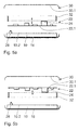
- FIG. 5a and 5b show circuit 22 and battery 10 in principle the same Stack arrangement, as in Figures 3 and 4.
- the circuit 22 is, however not directly on the battery 10 or the half-shell 30, but by a mounting element 32 added.
- the mounting element 32 has this suitable structures in which the component carrier 26 are clamped can.
- the concrete design of the structures must match the respective structural Be adapted to the circumstances. Such measures are known to the person skilled in the art well known, so that this will not be discussed in more detail.
- the mounting element 32 is adjacent arranged to the battery 10, the component side optionally in Direction of the half-shell 30 (FIG. 5a) or in the direction of the battery 10 (FIG. 5b) has.
- Such a mounting element 32 has the advantage that tensions, that can occur in the area of the battery 10 as a result of volume changes not be transferred directly to the circuit 22 and there to a mechanical damage.
- Connection technologies adapted to uniaxial assembly operations.
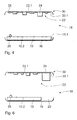
- Implant housing 18 occupies and thus spaces 20 remain, so can the alternative arrangement of the components of the implant outlined in FIG. 6 will be realized. According to this arrangement, electronic components 24 placed on the circuit 22 with a particularly high overall height such that they protrude into the free spaces 20 after the two components have been assembled.
- Fig. 7a and 7b are two other alternative design options for such a uniaxial arrangement of the components. Both alternatives are based on a battery 10 with a height profile, as they are has already been described in Fig. 1 b. 7a is the contour of the circuit 22 including the component carrier 26 to the height profile of the battery 10 customized. In the area 12 of the battery 10 with the smallest height extension are the electronic components 24 with the greatest overall height located (Fig. 7a). Alternatively, a circuit 22 with a flat component carrier 26 arranged adjacent to the half-shell 30, namely such that the highest electronic components 24 after assembly above the area 12 of the battery 10 are arranged with the smallest overall height.
- Figures 8a to 8f show a total of six alternative embodiments a bushing 28 which is used to establish the electrical connection between Battery 10 and circuit 22 can be used.
- the implementations 28 can be used as components during an SMT assembly process the circuit 22 are soldered. At which points ultimately one Soldering takes place or what orientation individual elements of the implementation 28 relative to the position of the components to be connected, must in individual cases be decided. Basically, however, is due to the uniaxial Structure of the functional components a significant simplification of the electrical Circuit diagram possible because only small distances are bridged Need to become. This leads to material savings and space savings.
- the bushings 28 listed by way of example are available with the circuit 22 via nail heads (Fig. 8a), adapters ( Figures 8b and 8c), curved pins (Fig.
- connection methods can be used waived to create the electrical connection become.
- electrical plug-in elements can be provided during assembly of the implant.
- plug-in elements are adequate for a person skilled in the art are known and from case to case the respective functional and structural Needs to be adjusted.
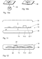
- Connecting elements 36 can be provided, as shown in Figures 10a and 10b are shown before and after the assembly of the components.
- the connection elements 36 contain a male and female contour, which in Stacking the components together and the components keep at a defined distance.
- you can click here A variety of alternative embodiments of the connection elements 36, such as are sufficiently known from the prior art.
- the essential criterion of the connection elements 36 is only that they allow a relative movement of the two components to each other. Out The snap connection shown is particularly useful for automation reasons on.
- FIG. 11 schematically shows a further alternative arrangement with a uniaxial component structure shown. Basically corresponds to they of the arrangement of circuit 22 and already presented in FIG. 3 Battery 10.
- a battery housing 38 is used for training at the same time the lower half-shell of the implant housing 18 is used.
- the battery housing 38 is made of a biocompatible at least in this area Material, especially titanium, made.
- one manufacturing step is omitted in the manufacturing process, namely that Place the battery 10 in one of the half shells of the implant housing 18.
- a subsequent filling of the battery 10 with electrolyte or another activation via an additional filling opening for use come, whereby the time of the energy-consuming start of the function of the implant can be determined.
- FIG. 12 shows a schematic Sectional view of an electromedical implant in which the implant housing 18 is completely replaced by the battery housing 38. All functional components - in this case the circuit 22 shown their electronic components 24 - are housed within the battery 10 and to protect them hermetically against the electrolyte of the Battery 10 are sealed.
- the circuit 22 can be sealed, for example in the immersion process with inert resins / immersion lacquers.
- the Dried resins / dip varnishes form a protective layer that the electrolyte cannot penetrate or attack. It can be used on two housing shells to be dispensed with.
- FIG. 13 is again intended to exemplify the uniaxial assembly of the functional Clarify components during the manufacture of an implant (indicated by the arrow).
- the arrangement and assembly sequence can vary.
- the implants manufactured in the manner described above should have their dimensions correspond to those of known implants. So you have one Overall height of approx. 5 to 7 mm.
- the metal shell of the implant housing takes from this 18 including applied foils for insulation and free space for the fixation of the components about 0.6 - 0.9 mm in claim.
- the battery 10 has a height profile (FIGS. 7a and 7b)
- the thickness of the battery usually varies between 1.5 to 4.5 mm, the remaining space for the circuit 22 is used.
Landscapes
- Health & Medical Sciences (AREA)
- Engineering & Computer Science (AREA)
- Biomedical Technology (AREA)
- Nuclear Medicine, Radiotherapy & Molecular Imaging (AREA)
- Radiology & Medical Imaging (AREA)
- Life Sciences & Earth Sciences (AREA)
- Animal Behavior & Ethology (AREA)
- General Health & Medical Sciences (AREA)
- Public Health (AREA)
- Veterinary Medicine (AREA)
- Connection Of Batteries Or Terminals (AREA)
- Electrotherapy Devices (AREA)
Abstract
Description
- Fig. 1a bis 1d
- eine schematische Drauf- und Seitenansichten auf Batterien für ein elektromedizinisches Implantat;
- Fig. 2a und 2b
- zwei schematische Draufsichten auf eine Halbschale eines Implantatsgehäuses mit einer auf der inneren Grundfläche angeordneten Batterie;
- Fig.3
- eine Schnittansicht auf eine Schaltungsanordnung im Implantat nach einer ersten Variante;
- Fig.4
- eine Schnittansicht auf eine Schaltungsanordnung im Implantat nach einer zweiten Variante;
- Fig. 5a und 5b
- zwei Schnittansichten auf alternative Anordnungen der Schaltung mit einem Montageelement;
- Fig. 6
- eine Schnittansicht auf eine weitere, alternative Schaltungsanordnung im Implantat mit einem Freiraum im Bereich des Implantatsgehäuses;
- Fig. 7a und 7b
- zwei Schnittansichten auf alternative Anordnungen mit einem zwischen Batterie und Schaltung abgestimmten Höhenprofil;
- Fig. 8a bis 8f
- eine perspektivische Detaildarstellung sechs, alternativer Durchführungen für die Erstellung einer elektrischen Verbindung;
- Fig. 9a und 9b
- eine Teilschnittansicht und eine vergrößerte Detailansicht durch die Batterie, Schaltung und einer Struktur zur Kompensation entladungsbedingter Volumenänderungen;
- Fig. 10a und 10b
- eine perspektivische Seitenansicht auf zwei Anbindungselemente zur Kompensation entladungsbedingter Volumenänderungen in geöffneter und geschlossener Form;
- Fig. 11
- eine Schnittansicht auf eine Anordnung, in der das Batteriegehäuse eine Halbschale des Implantatsgehäuses ersetzt;
- Fig. 12
- eine Schnittansicht auf ein Implantatsgehäuse, in der das Batteriegehäuse beide Halbschalen des Implantatsgehäuses ersetzt;
- Fig. 13
- eine Illustration des einachsigen Herstellungsverfahrens eines elektromedizinischen Implantats.
- 10
- Batterie
- 10.1
- Schmalseite der Batterie 10
- 10.2
- Flachseite der Batterie 10
- 10.3
- Unterseite der Batterie 10
- 12
- Abschnitt niedriger Bauhöhe
- 14
- Abschnitt größerer Bauhöhe
- 16
- untere Halbschale
- 18
- Implantatsgehäuse
- 18.1
- innere Grundfläche
- 20
- Freiraum
- 22
- Schaltung
- 22.1
- Unterseite der Schaltung 22
- 24
- elektronische Bauteile
- 26
- Bauteileträger
- 28
- Durchführung
- 30
- obere Halbschale
- 30.1
- Innenseite der oberen Halbschale 30
- 32
- Montageelement
- 34
- Strukturen zur Kompensation entladungsbedingten Anschwellens
- 36
- Anbindungselement
- 38
- Batteriegehäuse
Claims (20)
- Elektromedizinisches Implantat zur intrakardialen Herztherapie mit einem Implantatsgehäuse in dem funktionelle Komponenten des Implantats, nämlich eine Schaltung, eine Batterie und dergleichen, untergebracht sind, dadurch gekennzeichnet, dass die Batterie (10) eine Flachseite (10.2), eine Unterseite (10.3) und eine umlaufende Schmalseite (10.1) aufweist und die Batterie (10) mit ihrer Unterseite (10.3) auf eine innere Grundfläche (18.1) des Implantatsgehäuses (18) und die Schaltung (22) benachbart zu einer Flachseite (10.2) der Batterie (10) angeordnet ist.
- Elektromedizinisches Implantat nach Anspruch 1, dadurch gekennzeichnet, dass die Schaltung (22) einen Bauteileträger (26) mit Bestückungssatz (elektronische Bauteile (24)) umfasst und eine Unterseite (22.1) von Bauteileträger (26) und Schaltung (22) benachbart zur Flachseite (10.2) der Batterie (10) angeordnet ist.
- Elektromedizinisches Implantat nach Anspruch 2, dadurch gekennzeichnet, dass die Schaltung (22) an der Flachseite (10.2) der Batterie (10) fixiert ist.
- Elektromedizinisches Implantat nach Anspruch 3, dadurch gekennzeichnet, dass zwischen der Flachseite (10.2) der Batterie (10) und der Unterseite (22.1) der Schaltung (22) Strukturen (34) vorhanden sind, die ein entladungsbedingtes Anschwellen der Batterie (10) kompensieren.
- Elektromedizinisches Implantat nach Anspruch 4, dadurch gekennzeichnet, dass die Strukturen (34) Freiräume zwischen der Batterie (10) und der Schaltung (22) umfassen.
- Elektromedizinisches Implantat nach Anspruch 4, dadurch gekennzeichnet, dass die Strukturen (34) Anbindungselemente (36) zwischen der Batterie (10) und der Schaltung (22) umfassen, die eine Relativbewegung der Schaltung (22) zur Batterie (10) zulassen.
- Elektromedizinisches Implantat nach Anspruch 1, dadurch gekennzeichnet, dass die Schaltung (22) einen Bauteileträger (26) mit Bestückungssatz (elektronische Bauteile (24)) umfasst und die Unterseite (22.1) von Bauteileträger (26) und Schaltung (22) benachbart zu einer Innenseite (30.1) einer oberen Halbschale (30) des Implantatsgehäuses (18) angeordnet ist.
- Elektromedizinisches Implantat nach Anspruch 7, dadurch gekennzeichnet, dass das die Batterie (10) nicht die gesamte innere Grundfläche (18.1) des Implantatsgehäuses (18) ausfüllt, sondern kleine Freiräume (20) vorgesehen sind und die Schaltung (22) und die Batterie (10) so zueinander angeordnet sind, dass elektronische Bauteile (24) mit hoher Bauhöhe nach dem Montieren der Komponenten in diese Freiräume (20) ragen.
- Elektromedizinisches Implantat nach Anspruch 1, dadurch gekennzeichnet, dass die Flachseite (10.2) der Batterie (10) und die Schaltung (22) ein aufeinander abgestimmtes Höhenprofil aufweisen.
- Elektromedizinisches Implantat nach Anspruch 9, dadurch gekennzeichnet, dass die Schaltung (22) in ihrer Kontur dem Höhenprofil der Batterie (10) folgt und die elektronischen Bauteile (24) der Schaltung (22) so angeordnet sind, dass eine Gesamthöhe der beiden aufeinandergestapelten Komponenten minimiert ist.
- Elektromedizinisches Implantat nach Anspruch 1, 2, 7 oder 9, dadurch gekennzeichnet, dass ein Montageelement (32) vorgesehen ist, das die Schaltung (22) aufnimmt.
- Elektromedizinisches Implantat nach einem oder mehreren der Ansprüche 1 bis 11, dadurch gekennzeichnet, dass das weitere oder alle im Implantatsgehäuse (18) untergebrachten funktionellen Komponenten von der inneren Grundfläche des Implantatsgehäuses (18) ausgehend aufeinander gestapelt sind.
- Elektromedizinisches Implantat nach einem oder mehreren der Ansprüche 2 bis 12, dadurch gekennzeichnet, dass der Bestückungssatz der Schaltung (22) eine möglichst geringe Bauhöhe aufweist.
- Elektromedizinisches Implantat nach einem oder mehreren der Ansprüche 1 bis 13, dadurch gekennzeichnet, dass das Implantatsgehäuse (18) aus zwei Halbschalen (16, 30) besteht und eine der Halbschale (16, 30) gleichzeitig eine Gehäuseschale (38) der Batterie (10) ist.
- Elektromedizinisches Implantat nach einem oder mehreren der Ansprüche 1 bis 13, dadurch gekennzeichnet, dass das Implantatsgehäuse (18) aus zwei Halbschalen (16, 30) besteht und beide Halbschalen (16, 30) des Implantatsgehäuses (18) gleichzeitig die Gehäuseschalen (38) der Batterie (10) bilden und die Schaltung (22) sowie alle weiteren funktionellen Komponenten des Implantats hermetisch gegenüber einem Elektrolyt der Batterie (10) versiegelt sind.
- Elektromedizinisches Implantat nach Anspruch 14 oder 15, dadurch gekennzeichnet, dass die Halbschalen (16, 30) des Implantatsgehäuses (18) als Schnappschalen ausgebildet sind.
- Elektromedizinisches Implantat nach Anspruch 14 oder 15, dadurch gekennzeichnet, dass die Gehäuseschale (38) der Batterie (10) aus einem biokompatiblen Material besteht.
- Elektromedizinisches Implantat nach Anspruch 17, dadurch gekennzeichnet, dass die Gehäuseschale (38) aus Titan ist.
- Elektromedizinisches Implantat nach einem der vorhergehenden Ansprüche, dadurch gekennzeichnet, dass sich die Schaltung (22) über > 80%, insbesondere > 90%, besonders bevorzugt > 95% der Flachseite (10.2) der Batterie (10) erstreckt.
- Elektromedizinisches Implantat nach einem der vorhergehenden Ansprüche, dadurch gekennzeichnet, dass Batterie (10) und Schaltung (22) > 85%, insbesondere > 90%, besonders bevorzugt > 95% des gesamten Gehäusevolumens einnehmen.
Applications Claiming Priority (2)
| Application Number | Priority Date | Filing Date | Title |
|---|---|---|---|
| DE10247674 | 2002-10-09 | ||
| DE10247674A DE10247674A1 (de) | 2002-10-09 | 2002-10-09 | Elektromedizinisches Implantat zur interkardialen Herztherapie |
Publications (3)
| Publication Number | Publication Date |
|---|---|
| EP1407801A2 true EP1407801A2 (de) | 2004-04-14 |
| EP1407801A3 EP1407801A3 (de) | 2004-05-26 |
| EP1407801B1 EP1407801B1 (de) | 2006-04-12 |
Family
ID=32010467
Family Applications (1)
| Application Number | Title | Priority Date | Filing Date |
|---|---|---|---|
| EP03090334A Expired - Lifetime EP1407801B1 (de) | 2002-10-09 | 2003-10-07 | Elektromedizinisches Implantat zur interkardialen Herztherapie |
Country Status (4)
| Country | Link |
|---|---|
| US (1) | US7194310B2 (de) |
| EP (1) | EP1407801B1 (de) |
| AT (1) | ATE322930T1 (de) |
| DE (2) | DE10247674A1 (de) |
Cited By (3)
| Publication number | Priority date | Publication date | Assignee | Title |
|---|---|---|---|---|
| WO2005110539A1 (en) * | 2004-04-30 | 2005-11-24 | Medtronic, Inc | Battery isolator for implantable medical device |
| EP1647302A1 (de) | 2004-10-12 | 2006-04-19 | BIOTRONIK CRM Patent AG | Elektromedizinisches Implantat |
| US7118828B2 (en) | 2002-03-11 | 2006-10-10 | Quallion Llc | Implantable battery |
Families Citing this family (6)
| Publication number | Priority date | Publication date | Assignee | Title |
|---|---|---|---|---|
| US20060247715A1 (en) * | 2005-04-29 | 2006-11-02 | Youker Nick A | Method and apparatus for an implantable pulse generator with a stacked battery and capacitor |
| US8874214B2 (en) * | 2006-08-28 | 2014-10-28 | Cardiac Pacemakers, Inc. | Implantable pulse generator with a stacked capacitor, battery, and electronics |
| US7979126B2 (en) * | 2006-10-18 | 2011-07-12 | Boston Scientific Neuromodulation Corporation | Orientation-independent implantable pulse generator |
| US8694101B2 (en) * | 2008-01-28 | 2014-04-08 | Biotronik Crm Patent Ag | Coupling element |
| US8718774B2 (en) * | 2009-04-23 | 2014-05-06 | Cardiac Pacemakers, Inc. | Housings for implantable medical devices and methods for forming housings |
| US9403024B2 (en) | 2013-09-05 | 2016-08-02 | Boston Scientific Neuromodulation Corporation | Construction for an implantable medical device employing an internal support structure |
Citations (3)
| Publication number | Priority date | Publication date | Assignee | Title |
|---|---|---|---|---|
| WO1999006107A1 (en) | 1997-07-30 | 1999-02-11 | Intermedics Inc. | Cardiac stimulator having stackable microelectronic components with self-addressing scheme |
| US6026325A (en) | 1998-06-18 | 2000-02-15 | Pacesetter, Inc. | Implantable medical device having an improved packaging system and method for making electrical connections |
| US6251124B1 (en) | 1998-05-06 | 2001-06-26 | Cardiac Pacemakers, Inc. | Cardiac rhythm management system having multi-capacitor module |
Family Cites Families (7)
| Publication number | Priority date | Publication date | Assignee | Title |
|---|---|---|---|---|
| US5144946A (en) * | 1991-08-05 | 1992-09-08 | Siemens Pacesetter, Inc. | Combined pacemaker substrate and electrical interconnect and method of assembly |
| US5370669A (en) * | 1993-11-17 | 1994-12-06 | Intermedics, Inc. | Implantable cardiac defibrillator with layered package |
| US5814090A (en) * | 1995-06-07 | 1998-09-29 | Angeion Corporation | Implantable medical device having heat-shrink conforming shield |
| US5674260A (en) * | 1996-02-23 | 1997-10-07 | Pacesetter, Inc. | Apparatus and method for mounting an activity sensor or other component within a pacemaker using a contoured hybrid lid |
| US6445948B1 (en) * | 1998-04-03 | 2002-09-03 | Medtronic, Inc. | Implantable medical device having a substantially flat battery |
| DE10041728A1 (de) * | 2000-08-25 | 2002-03-21 | Implex Hear Tech Ag | Implantierbare medizinische Vorrichtung mit einem hermetisch dichten Gehäuse |
| US6498951B1 (en) * | 2000-10-13 | 2002-12-24 | Medtronic, Inc. | Implantable medical device employing integral housing for a formable flat battery |
-
2002
- 2002-10-09 DE DE10247674A patent/DE10247674A1/de not_active Withdrawn
-
2003
- 2003-10-07 US US10/680,726 patent/US7194310B2/en not_active Expired - Lifetime
- 2003-10-07 DE DE50302942T patent/DE50302942D1/de not_active Expired - Lifetime
- 2003-10-07 AT AT03090334T patent/ATE322930T1/de not_active IP Right Cessation
- 2003-10-07 EP EP03090334A patent/EP1407801B1/de not_active Expired - Lifetime
Patent Citations (3)
| Publication number | Priority date | Publication date | Assignee | Title |
|---|---|---|---|---|
| WO1999006107A1 (en) | 1997-07-30 | 1999-02-11 | Intermedics Inc. | Cardiac stimulator having stackable microelectronic components with self-addressing scheme |
| US6251124B1 (en) | 1998-05-06 | 2001-06-26 | Cardiac Pacemakers, Inc. | Cardiac rhythm management system having multi-capacitor module |
| US6026325A (en) | 1998-06-18 | 2000-02-15 | Pacesetter, Inc. | Implantable medical device having an improved packaging system and method for making electrical connections |
Cited By (6)
| Publication number | Priority date | Publication date | Assignee | Title |
|---|---|---|---|---|
| US7118828B2 (en) | 2002-03-11 | 2006-10-10 | Quallion Llc | Implantable battery |
| WO2005110539A1 (en) * | 2004-04-30 | 2005-11-24 | Medtronic, Inc | Battery isolator for implantable medical device |
| US8041427B2 (en) | 2004-04-30 | 2011-10-18 | Medtronic, Inc. | Battery isolator for implantable medical device |
| EP1647302A1 (de) | 2004-10-12 | 2006-04-19 | BIOTRONIK CRM Patent AG | Elektromedizinisches Implantat |
| EP1944061A2 (de) | 2004-10-12 | 2008-07-16 | BIOTRONIK CRM Patent AG | Elektromedizinisches Implantat |
| EP1944061A3 (de) * | 2004-10-12 | 2008-10-29 | BIOTRONIK CRM Patent AG | Elektromedizinisches Implantat |
Also Published As
| Publication number | Publication date |
|---|---|
| EP1407801B1 (de) | 2006-04-12 |
| ATE322930T1 (de) | 2006-04-15 |
| DE50302942D1 (de) | 2006-05-24 |
| DE10247674A1 (de) | 2004-04-22 |
| EP1407801A3 (de) | 2004-05-26 |
| US20040230250A1 (en) | 2004-11-18 |
| US7194310B2 (en) | 2007-03-20 |
Similar Documents
| Publication | Publication Date | Title |
|---|---|---|
| DE60125213T2 (de) | Implantierbares medizinisches gerät mit einem integralen gehäuse für eine verformbare flache batterie | |
| DE69200526T3 (de) | Implantierbarer puls-generator. | |
| DE60128958T2 (de) | Verfahren zum verbinden von anoden und kathoden in einem flachen kondensator | |
| DE69931765T2 (de) | Verfahren zur herstellung eines flachen elektrolytkondensators zur verwendung in einem defibrillator | |
| US7647110B2 (en) | Modular implantable medical device and manufacturing method therefor | |
| DE69323374T2 (de) | Klappbare Kissenelektrode zur Herzentflimmerung mit einem Gebiet ohne Leitern, welches als ein Scharnier dient | |
| DE60128095T2 (de) | Implantierbare medische vorrichtung mit flachem elektrolytkondensator mit kathode/becher elektrische verbindungen | |
| DE60106451T2 (de) | Implantierbares medizinisches gerät mit einem flachen elektrolytkondensator mit angepassten anodeschichten | |
| DE102008021064A1 (de) | Anschlussgehäuse für ein elektromedizinisches Implantat | |
| DE60303594T2 (de) | Verfahren zum Herstellen von Anodenschichten flacher Elektrolytkondensatoren für implantierbare medizinische Vorrichtungen | |
| WO2004009178A1 (en) | Ultrasonically welded components in an implantable medical device | |
| DE4214429B4 (de) | Batterie und Verfahren zur Herstellung einer Batterie mit einer Mehrzahl von elektrochemischen Zellen | |
| EP1407801B1 (de) | Elektromedizinisches Implantat zur interkardialen Herztherapie | |
| EP1691432B1 (de) | Galvanische Zelle | |
| EP3829702B1 (de) | Implantat und verfahren zur montage eines implantats | |
| EP2140909A1 (de) | Medizinisches Implantat | |
| DE3152726T1 (de) | Implantierbare Herzelektrode zur Defibrillation | |
| DE69931902T2 (de) | Verfahren zur herstellung eines implantierbaren geräts mit flachem multischicht-elektrolytkondensator | |
| DE202007018766U1 (de) | Kontaktmodul für ein medizinisches Implantat | |
| CN113614997B (zh) | 用于医疗装置的电池组合件 | |
| DE102007011310B4 (de) | Medizinisches Implantat und Verfahren zur Herstellung desselben | |
| WO2020025364A1 (de) | Implantat und verfahren zum herstellen eines implantats | |
| EP3829705B1 (de) | Implantat | |
| EP4618169A1 (de) | Batterie mit einem elektrodenstapel sowie verfahren zur herstellung einer batterie mit einem elektrodenstapel | |
| WO2025012013A1 (de) | Elektrische durchführung und energiespeicher mit einer solchen durchführung |
Legal Events
| Date | Code | Title | Description |
|---|---|---|---|
| PUAI | Public reference made under article 153(3) epc to a published international application that has entered the european phase |
Free format text: ORIGINAL CODE: 0009012 |
|
| PUAL | Search report despatched |
Free format text: ORIGINAL CODE: 0009013 |
|
| AK | Designated contracting states |
Kind code of ref document: A2 Designated state(s): AT BE BG CH CY CZ DE DK EE ES FI FR GB GR HU IE IT LI LU MC NL PT RO SE SI SK TR |
|
| AX | Request for extension of the european patent |
Extension state: AL LT LV MK |
|
| AK | Designated contracting states |
Kind code of ref document: A3 Designated state(s): AT BE BG CH CY CZ DE DK EE ES FI FR GB GR HU IE IT LI LU MC NL PT RO SE SI SK TR |
|
| AX | Request for extension of the european patent |
Extension state: AL LT LV MK |
|
| 17P | Request for examination filed |
Effective date: 20041126 |
|
| AKX | Designation fees paid |
Designated state(s): AT BE BG CH CY CZ DE DK EE ES FI FR GB GR HU IE IT LI LU MC NL PT RO SE SI SK TR |
|
| 17Q | First examination report despatched |
Effective date: 20050405 |
|
| GRAP | Despatch of communication of intention to grant a patent |
Free format text: ORIGINAL CODE: EPIDOSNIGR1 |
|
| GRAS | Grant fee paid |
Free format text: ORIGINAL CODE: EPIDOSNIGR3 |
|
| GRAA | (expected) grant |
Free format text: ORIGINAL CODE: 0009210 |
|
| AK | Designated contracting states |
Kind code of ref document: B1 Designated state(s): AT BE BG CH CY CZ DE DK EE ES FI FR GB GR HU IE IT LI LU MC NL PT RO SE SI SK TR |
|
| PG25 | Lapsed in a contracting state [announced via postgrant information from national office to epo] |
Ref country code: IT Free format text: LAPSE BECAUSE OF FAILURE TO SUBMIT A TRANSLATION OF THE DESCRIPTION OR TO PAY THE FEE WITHIN THE PRESCRIBED TIME-LIMIT;WARNING: LAPSES OF ITALIAN PATENTS WITH EFFECTIVE DATE BEFORE 2007 MAY HAVE OCCURRED AT ANY TIME BEFORE 2007. THE CORRECT EFFECTIVE DATE MAY BE DIFFERENT FROM THE ONE RECORDED. Effective date: 20060412 Ref country code: FI Free format text: LAPSE BECAUSE OF FAILURE TO SUBMIT A TRANSLATION OF THE DESCRIPTION OR TO PAY THE FEE WITHIN THE PRESCRIBED TIME-LIMIT Effective date: 20060412 Ref country code: IE Free format text: LAPSE BECAUSE OF FAILURE TO SUBMIT A TRANSLATION OF THE DESCRIPTION OR TO PAY THE FEE WITHIN THE PRESCRIBED TIME-LIMIT Effective date: 20060412 Ref country code: SK Free format text: LAPSE BECAUSE OF FAILURE TO SUBMIT A TRANSLATION OF THE DESCRIPTION OR TO PAY THE FEE WITHIN THE PRESCRIBED TIME-LIMIT Effective date: 20060412 Ref country code: SI Free format text: LAPSE BECAUSE OF FAILURE TO SUBMIT A TRANSLATION OF THE DESCRIPTION OR TO PAY THE FEE WITHIN THE PRESCRIBED TIME-LIMIT Effective date: 20060412 Ref country code: CZ Free format text: LAPSE BECAUSE OF FAILURE TO SUBMIT A TRANSLATION OF THE DESCRIPTION OR TO PAY THE FEE WITHIN THE PRESCRIBED TIME-LIMIT Effective date: 20060412 Ref country code: RO Free format text: LAPSE BECAUSE OF FAILURE TO SUBMIT A TRANSLATION OF THE DESCRIPTION OR TO PAY THE FEE WITHIN THE PRESCRIBED TIME-LIMIT Effective date: 20060412 |
|
| REG | Reference to a national code |
Ref country code: GB Ref legal event code: FG4D Free format text: NOT ENGLISH |
|
| REG | Reference to a national code |
Ref country code: CH Ref legal event code: EP |
|
| REF | Corresponds to: |
Ref document number: 50302942 Country of ref document: DE Date of ref document: 20060524 Kind code of ref document: P |
|
| REG | Reference to a national code |
Ref country code: IE Ref legal event code: FG4D Free format text: LANGUAGE OF EP DOCUMENT: GERMAN |
|
| REG | Reference to a national code |
Ref country code: SE Ref legal event code: TRGR |
|
| GBT | Gb: translation of ep patent filed (gb section 77(6)(a)/1977) |
Effective date: 20060607 |
|
| PG25 | Lapsed in a contracting state [announced via postgrant information from national office to epo] |
Ref country code: DK Free format text: LAPSE BECAUSE OF FAILURE TO SUBMIT A TRANSLATION OF THE DESCRIPTION OR TO PAY THE FEE WITHIN THE PRESCRIBED TIME-LIMIT Effective date: 20060712 |
|
| PG25 | Lapsed in a contracting state [announced via postgrant information from national office to epo] |
Ref country code: ES Free format text: LAPSE BECAUSE OF FAILURE TO SUBMIT A TRANSLATION OF THE DESCRIPTION OR TO PAY THE FEE WITHIN THE PRESCRIBED TIME-LIMIT Effective date: 20060723 |
|
| PG25 | Lapsed in a contracting state [announced via postgrant information from national office to epo] |
Ref country code: PT Free format text: LAPSE BECAUSE OF FAILURE TO SUBMIT A TRANSLATION OF THE DESCRIPTION OR TO PAY THE FEE WITHIN THE PRESCRIBED TIME-LIMIT Effective date: 20060912 |
|
| PG25 | Lapsed in a contracting state [announced via postgrant information from national office to epo] |
Ref country code: MC Free format text: LAPSE BECAUSE OF NON-PAYMENT OF DUE FEES Effective date: 20061031 |
|
| REG | Reference to a national code |
Ref country code: IE Ref legal event code: FD4D |
|
| ET | Fr: translation filed | ||
| PLBE | No opposition filed within time limit |
Free format text: ORIGINAL CODE: 0009261 |
|
| STAA | Information on the status of an ep patent application or granted ep patent |
Free format text: STATUS: NO OPPOSITION FILED WITHIN TIME LIMIT |
|
| 26N | No opposition filed |
Effective date: 20070115 |
|
| BERE | Be: lapsed |
Owner name: BIOTRONIK G.M.B.H. & CO. KG Effective date: 20061031 |
|
| PG25 | Lapsed in a contracting state [announced via postgrant information from national office to epo] |
Ref country code: AT Free format text: LAPSE BECAUSE OF NON-PAYMENT OF DUE FEES Effective date: 20061007 |
|
| PG25 | Lapsed in a contracting state [announced via postgrant information from national office to epo] |
Ref country code: GR Free format text: LAPSE BECAUSE OF FAILURE TO SUBMIT A TRANSLATION OF THE DESCRIPTION OR TO PAY THE FEE WITHIN THE PRESCRIBED TIME-LIMIT Effective date: 20060713 |
|
| PG25 | Lapsed in a contracting state [announced via postgrant information from national office to epo] |
Ref country code: BG Free format text: LAPSE BECAUSE OF FAILURE TO SUBMIT A TRANSLATION OF THE DESCRIPTION OR TO PAY THE FEE WITHIN THE PRESCRIBED TIME-LIMIT Effective date: 20060712 Ref country code: EE Free format text: LAPSE BECAUSE OF FAILURE TO SUBMIT A TRANSLATION OF THE DESCRIPTION OR TO PAY THE FEE WITHIN THE PRESCRIBED TIME-LIMIT Effective date: 20060412 |
|
| PG25 | Lapsed in a contracting state [announced via postgrant information from national office to epo] |
Ref country code: TR Free format text: LAPSE BECAUSE OF FAILURE TO SUBMIT A TRANSLATION OF THE DESCRIPTION OR TO PAY THE FEE WITHIN THE PRESCRIBED TIME-LIMIT Effective date: 20060412 Ref country code: LU Free format text: LAPSE BECAUSE OF NON-PAYMENT OF DUE FEES Effective date: 20061007 Ref country code: HU Free format text: LAPSE BECAUSE OF FAILURE TO SUBMIT A TRANSLATION OF THE DESCRIPTION OR TO PAY THE FEE WITHIN THE PRESCRIBED TIME-LIMIT Effective date: 20061013 |
|
| PG25 | Lapsed in a contracting state [announced via postgrant information from national office to epo] |
Ref country code: CY Free format text: LAPSE BECAUSE OF FAILURE TO SUBMIT A TRANSLATION OF THE DESCRIPTION OR TO PAY THE FEE WITHIN THE PRESCRIBED TIME-LIMIT Effective date: 20060412 |
|
| PGFP | Annual fee paid to national office [announced via postgrant information from national office to epo] |
Ref country code: NL Payment date: 20081023 Year of fee payment: 6 |
|
| PGFP | Annual fee paid to national office [announced via postgrant information from national office to epo] |
Ref country code: IT Payment date: 20081027 Year of fee payment: 6 |
|
| PG25 | Lapsed in a contracting state [announced via postgrant information from national office to epo] |
Ref country code: BE Free format text: LAPSE BECAUSE OF FAILURE TO SUBMIT A TRANSLATION OF THE DESCRIPTION OR TO PAY THE FEE WITHIN THE PRESCRIBED TIME-LIMIT Effective date: 20061031 |
|
| REG | Reference to a national code |
Ref country code: NL Ref legal event code: V1 Effective date: 20100501 |
|
| PG25 | Lapsed in a contracting state [announced via postgrant information from national office to epo] |
Ref country code: NL Free format text: LAPSE BECAUSE OF NON-PAYMENT OF DUE FEES Effective date: 20100501 |
|
| PG25 | Lapsed in a contracting state [announced via postgrant information from national office to epo] |
Ref country code: IT Free format text: LAPSE BECAUSE OF NON-PAYMENT OF DUE FEES Effective date: 20091007 |
|
| REG | Reference to a national code |
Ref country code: DE Ref legal event code: R082 Ref document number: 50302942 Country of ref document: DE Representative=s name: RANDOLL, SOEREN, DIPL.-CHEM. UNIV. DR. RER. NA, DE Ref country code: DE Ref legal event code: R082 Ref document number: 50302942 Country of ref document: DE |
|
| REG | Reference to a national code |
Ref country code: DE Ref legal event code: R081 Ref document number: 50302942 Country of ref document: DE Owner name: BIOTRONIK SE & CO. KG, DE Free format text: FORMER OWNER: BIOTRONIK GMBH & CO. KG, 12359 BERLIN, DE Effective date: 20111219 |
|
| PGFP | Annual fee paid to national office [announced via postgrant information from national office to epo] |
Ref country code: FR Payment date: 20121113 Year of fee payment: 10 |
|
| PGFP | Annual fee paid to national office [announced via postgrant information from national office to epo] |
Ref country code: SE Payment date: 20121024 Year of fee payment: 10 Ref country code: GB Payment date: 20121023 Year of fee payment: 10 |
|
| REG | Reference to a national code |
Ref country code: SE Ref legal event code: EUG |
|
| GBPC | Gb: european patent ceased through non-payment of renewal fee |
Effective date: 20131007 |
|
| PG25 | Lapsed in a contracting state [announced via postgrant information from national office to epo] |
Ref country code: GB Free format text: LAPSE BECAUSE OF NON-PAYMENT OF DUE FEES Effective date: 20131007 |
|
| REG | Reference to a national code |
Ref country code: FR Ref legal event code: ST Effective date: 20140630 |
|
| PG25 | Lapsed in a contracting state [announced via postgrant information from national office to epo] |
Ref country code: FR Free format text: LAPSE BECAUSE OF NON-PAYMENT OF DUE FEES Effective date: 20131031 Ref country code: SE Free format text: LAPSE BECAUSE OF NON-PAYMENT OF DUE FEES Effective date: 20131008 |
|
| PGFP | Annual fee paid to national office [announced via postgrant information from national office to epo] |
Ref country code: DE Payment date: 20221025 Year of fee payment: 20 |
|
| PGFP | Annual fee paid to national office [announced via postgrant information from national office to epo] |
Ref country code: CH Payment date: 20221027 Year of fee payment: 20 |
|
| P01 | Opt-out of the competence of the unified patent court (upc) registered |
Effective date: 20230607 |
|
| REG | Reference to a national code |
Ref country code: DE Ref legal event code: R071 Ref document number: 50302942 Country of ref document: DE |
|
| REG | Reference to a national code |
Ref country code: CH Ref legal event code: PL |