EP1407701B1 - Mahlarm mit zu reinigungszwecken abnehmbarem ende - Google Patents
Mahlarm mit zu reinigungszwecken abnehmbarem ende Download PDFInfo
- Publication number
- EP1407701B1 EP1407701B1 EP02745433A EP02745433A EP1407701B1 EP 1407701 B1 EP1407701 B1 EP 1407701B1 EP 02745433 A EP02745433 A EP 02745433A EP 02745433 A EP02745433 A EP 02745433A EP 1407701 B1 EP1407701 B1 EP 1407701B1
- Authority
- EP
- European Patent Office
- Prior art keywords
- arm
- tool
- assembly
- respect
- mentioned
- Prior art date
- Legal status (The legal status is an assumption and is not a legal conclusion. Google has not performed a legal analysis and makes no representation as to the accuracy of the status listed.)
- Expired - Lifetime
Links
- 238000004140 cleaning Methods 0.000 title claims abstract description 11
- 230000002093 peripheral effect Effects 0.000 claims abstract description 7
- 230000005540 biological transmission Effects 0.000 claims description 8
- 230000014759 maintenance of location Effects 0.000 claims description 7
- 230000001681 protective effect Effects 0.000 abstract 1
- 238000000605 extraction Methods 0.000 description 4
- 235000013305 food Nutrition 0.000 description 4
- 230000000694 effects Effects 0.000 description 2
- 238000002360 preparation method Methods 0.000 description 2
- 230000008878 coupling Effects 0.000 description 1
- 238000010168 coupling process Methods 0.000 description 1
- 238000005859 coupling reaction Methods 0.000 description 1
- 230000008030 elimination Effects 0.000 description 1
- 238000003379 elimination reaction Methods 0.000 description 1
- 230000007717 exclusion Effects 0.000 description 1
- 230000002349 favourable effect Effects 0.000 description 1
- 230000002906 microbiologic effect Effects 0.000 description 1
- 244000005700 microbiome Species 0.000 description 1
- 230000035515 penetration Effects 0.000 description 1
- 235000021067 refined food Nutrition 0.000 description 1
- XLYOFNOQVPJJNP-UHFFFAOYSA-N water Substances O XLYOFNOQVPJJNP-UHFFFAOYSA-N 0.000 description 1
Images

Classifications
-
- A—HUMAN NECESSITIES
- A47—FURNITURE; DOMESTIC ARTICLES OR APPLIANCES; COFFEE MILLS; SPICE MILLS; SUCTION CLEANERS IN GENERAL
- A47J—KITCHEN EQUIPMENT; COFFEE MILLS; SPICE MILLS; APPARATUS FOR MAKING BEVERAGES
- A47J43/00—Implements for preparing or holding food, not provided for in other groups of this subclass
- A47J43/04—Machines for domestic use not covered elsewhere, e.g. for grinding, mixing, stirring, kneading, emulsifying, whipping or beating foodstuffs, e.g. power-driven
- A47J43/07—Parts or details, e.g. mixing tools, whipping tools
- A47J43/0705—Parts or details, e.g. mixing tools, whipping tools for machines with tools driven from the upper side
- A47J43/0711—Parts or details, e.g. mixing tools, whipping tools for machines with tools driven from the upper side mixing, whipping or cutting tools
Definitions
- the present invention refers to a mincer arm, of the ones which are connected in a removable way respect to an operation motor block, being applied for several functions, especially, but without limitative character, in the preparation of food.
- this kind of devices are used in a generalized way in the preparation of food, field in which some extreme hygienic conditions are required, so that the cleaning of the elements has a fundamental importance.
- the mentioned devices are carried out, generally with the tool holding arm in detachable disposition respect to the motor block, with which the arm cleaning, which is the part which enters in touch with the products on which the application operations act, results easier to be carried out, especially because with the independence of the arm there is no risk that water enters in the motor block where the electric elements are housed.
- the part with greater incidence in relation to the products on which the application operations act is the end of the arm where the actuating tool is incorporated and a protection situated around the same.
- the products on which is acted penetrate in all the openings, resulting it difficult to eliminate all the remains.
- Patent BE 628800 of the year 1963, includes a solution, which is already of the public domain, on an arm in which the tool is incorporated in an assembly block on the corresponding protection part, which is joined in a disassemblable way with the body of the arm by means of a ferrule.
- This solution allows to separate the block bearing the tool respect to the arm body, but to disengage the tool it is moreover necessary to disassemble the component set from the mentioned tool bearing block, which can only be carried out after having separated the block respect to the arm body, supposing all this a set of operations which are complicate and expensive.
- a mincer arm is proposed, of the kind which can be connected to a motor block for its use, in which a constructive and functional realization has been foreseen which allows the simple and fast disassembly of the element components and without the need to use tools.
- This arm object of the invention, includes a tubular body, through whose inside a shaft is included which holds at the end the actuating tool, incorporating the mentioned arm at the rear end a connection for the functional union with the operating motor block, while at the other end a peripheral protection of the actuating tool is incorporated, which in a characteristic way is made up of an independent piece situated in detachable connection.
- the mentioned peripheral protection part of the tool arm is fixed on a bushing inserted and solidarized respect to the tubular body, establishing the fastening between the protection part and the bushing, by means of thread, bayonet coupling, or any other conventional solution able to allow the disassembly by means of only an actuation with the hand on the mentioned protection part.
- the rotary transmission shaft incorporates at the end an extension piece connected by means of fitting with free extraction, remaining the end of the transmission shaft guided and centred by means of a bearing embedded in a support, while at the supporting extension piece of the tool passes through another support foreseen of watertight means, the mentioned supports are included fastened by the assembly of the protecting part of the tool.
- the constructive assembly of the arm end is this way very simple referring to its realization, determining an effective watertight disposition and fastening of the shaft, with the possibility of a very easy disassembly of the whole set, only actuating with the hand on the protecting part of the tool, thanks to the configuration to the mentioned part itself and this without the need to use tools.
- the set offers some perfect security conditions for the use of the arm, while if the mentioned protecting arm is not connected, the extension piece the tool has leaves its connection with the transmission shaft when the arm is put into using position, which avoids that the tool can be actuated if the mentioned protection part is not incorporated in the assembly.
- the mentioned arm, object of the invention certainly has some very advantageous features, acquiring own life and preferable character respect to the known arms with the same application.
- the object of the invention is a mincer arm of the ones used connected to an operation motor block, fundamentally for applications for food processing, without the exclusion of the possibility of its use for other purposes.
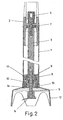
- the arm is made up of a tubular body (1) at one end of which a connection (2) is incorporated for the functional union respect to the actuation motor block, with disassembly possibility.
- a rotary shaft (3) is axially included, which at one end is foreseen of a gear (4) for the functional connection respect to the rotary actuation means included in the motor block, while at the other end of the mentioned shaft (3) an extension piece (5) is incorporated on which an actuation tool (6) is situated in the operations to be carried out, such as a cutting blade or any other kind of actuating tool by means of rotation.
- the assembly of the shaft (3) respect to the body (1) is established by means of a guiding bearing (7) incorporated on the rear end of the mentioned shaft (3) and which engages inside the connection (2), and by means of a support (8), through which the other end of the mentioned shaft (3) passes, at which support (8) a bearing (9) which establishes the guiding and the centering of the shaft (3) is embedded.
- the extension piece (5) passes in turn through another support (10), foreseen of watertight means, by means of which the centering and guiding of the mentioned extension piece (5) is established, which is connected by means of a solidary rotary engagement but with freedom of extraction with respect to the transmission shaft (3).
- a bushing (11) is engaged and solidarily fixed. This bushing determines a connection respect to which the assembly of an independent peripheral protection part (12) of the tool (6) is established.
- the assembly connection of the mentioned protection part (12), respect to the bushing (11), is established by means of any system which allows a fast and easy disconnection for the disassembly, such as a threaded fixing, of the kind with bayonet, or any other similar solution, so that, taking advantage of the configuration of the mentioned part (12) itself, it can be disconnected actuating on it with the hand, without the need of any tools.
- the tool (6) shall be incorporated at the end of the extension piece (5) after the connection of the part (12) in its assembly, as the mentioned tool (6) is greater than the hole of the mentioned part (12).
- the supports (8) and (10) are housed inside the bushing (11), respect to which they remain fastened in the assembly by retention by means of the protection part (12) of the tool (6), so that when the indicated part is disconnected (12), the mentioned supports (8) and (10) can be extracted.
- the disposition of the protection part (12) assures the assembly of the whole set, allowing by means of its disconnection the disassembly of the whole set without the need of tools, establishing the mentioned part (12) moreover a security which avoids the operation of the tool (6) when it is not incorporated and thus when the tool (6) is not protected peripherally, so as to avoid accidents, as if the mentioned part (12) is not incorporated in the assembly, the support (10) of the extension piece (5) is without retention, so that when the arm is put in working position, the mentioned extension piece, at which the tool (6) is incorporated, leaves the connection with the transmission shaft (3), resulting that the tool (6) is not actuated.
- the assembly according to the described disposition, to avoid the operation of the tool (6) when the protection part (12) is not incorporated, is a non limitative realization example, being it possible to adopt other dispositions with the same effect within the fundamental concept of the invention, which is the determination of the peripheral protection of the tool (6) by means of which an independent part (12) which can be disconnected without the need of tools, by simply actuating on it with the hand, for the disassembly of the arm set.
- extension piece (5) could be anchored with a fixed retention respect to the transmission shaft (3) and this one situated with pushing of a spring towards the extraction, which would produce the same effect of operation impossibility of the tool (6) when the protection part (12) is not incorporated, because the shaft (3) would be disconnected from the operation means of the motor block, thanks to the pushing towards the extraction.
- both unions (13) and (14) are included in the assembly, by means of which a watertightness is determined, which avoids the penetration of the processed products towards the inside. Nevertheless, when the part (12) is disconnected during the disassembly, the mentioned unions (13) and (14) remain free and can be disassembled, to carry out their cleaning and that of their seating in the assembly.
Landscapes
- Engineering & Computer Science (AREA)
- Mechanical Engineering (AREA)
- Food Science & Technology (AREA)
- Polishing Bodies And Polishing Tools (AREA)
- Crushing And Pulverization Processes (AREA)
- Manipulator (AREA)
- Crushing And Grinding (AREA)
- Food-Manufacturing Devices (AREA)
- Brushes (AREA)
- Knives (AREA)
- Light Guides In General And Applications Therefor (AREA)
Claims (3)
- Mahlarm mit zum Reinigen entfernbarem Ende, von der Art, die ein röhrenförmiges Ende (1) aufweist, das an einem Ende mit einer Kupplung (2) für eine lösbare Verbindung mit einem Motorblock versehen ist, axial eine Drehwelle (3) umfassend, die an ihrem Ende ein Werkzeug (6) aufweist, um das ein Umfangsschutz vorgesehen ist, der in einer lösbaren Verbindung in Bezug auf den Körper (1) angeschlossen ist, dadurch gekennzeichnet, dass der Umfangsschutz aus einem unabhängigen Teil (12) gebildet ist, der die Halterung von zwei Lagern (8) und (10) gewährleistet, die die Montage der Welle (3) und einer das Werkzeug (6) tragenden trennbaren Verlängerung (5) gewährleisten, so dass dann, wenn der Teil (12) relativ zu dem Körper (1) gelöst wird, die Welle (3) nicht mehr gehalten wird und am unteren Teil herausgenommen werden kann.
- Mahlarm mit zum Reinigen entfernbarem Ende nach Anspruch 1, dadurch gekennzeichnet, dass der Schutzteil (12) einstückig in Bezug auf den röhrenförmigen Körper (1) befestigt ist.
- Mahlarm mit zum Reinigen entfernbarem Ende nach den Ansprüchen 1 und 2, dadurch gekennzeichnet, dass der Schutzteil (12) bei der Montage eine Halterung der Betätigungskupplung des Werkzeugs (6) zusammen mit der Halterung der Getriebewelle (3) bei der Montage herstellt.
Applications Claiming Priority (3)
| Application Number | Priority Date | Filing Date | Title |
|---|---|---|---|
| ES200101544A ES2182707B2 (es) | 2001-07-03 | 2001-07-03 | Brazo triturador con el extremo desmontable para limpieza |
| ES200101544 | 2001-07-03 | ||
| PCT/ES2002/000317 WO2003003889A1 (es) | 2001-07-03 | 2002-06-28 | Brazo triturador con el extremo desmontable para limpieza |
Publications (2)
| Publication Number | Publication Date |
|---|---|
| EP1407701A1 EP1407701A1 (de) | 2004-04-14 |
| EP1407701B1 true EP1407701B1 (de) | 2005-01-26 |
Family
ID=8498270
Family Applications (1)
| Application Number | Title | Priority Date | Filing Date |
|---|---|---|---|
| EP02745433A Expired - Lifetime EP1407701B1 (de) | 2001-07-03 | 2002-06-28 | Mahlarm mit zu reinigungszwecken abnehmbarem ende |
Country Status (7)
| Country | Link |
|---|---|
| EP (1) | EP1407701B1 (de) |
| AT (1) | ATE287657T1 (de) |
| AU (1) | AU2002317177B2 (de) |
| DE (1) | DE60202772T2 (de) |
| ES (1) | ES2182707B2 (de) |
| PT (1) | PT1407701E (de) |
| WO (1) | WO2003003889A1 (de) |
Cited By (1)
| Publication number | Priority date | Publication date | Assignee | Title |
|---|---|---|---|---|
| US8033712B2 (en) | 2006-01-20 | 2011-10-11 | Hameur S.A. | Immersion mixer |
Families Citing this family (3)
| Publication number | Priority date | Publication date | Assignee | Title |
|---|---|---|---|---|
| FR2854562B1 (fr) * | 2003-05-09 | 2005-07-01 | Dito Sama | Outil de machine de traitement de produits alimentaire, notamment de type mixeur, et machine equipee d'un tel outil |
| CN101193581B (zh) | 2005-06-10 | 2010-11-10 | 皇家飞利浦电子股份有限公司 | 搅拌器装备和食物加工器 |
| GB2469639B (en) | 2009-04-21 | 2016-11-02 | Kenwood Ltd | Wand attachments for hand-held electric blenders |
Family Cites Families (4)
| Publication number | Priority date | Publication date | Assignee | Title |
|---|---|---|---|---|
| DE4301209C2 (de) * | 1993-01-19 | 1995-06-08 | Maweva Holding Ag Ltd Rickenba | Handrührgerät |
| FR2770121B1 (fr) * | 1997-10-29 | 2004-10-22 | Robot Coupe Sa | Mixer plongeant |
| FR2766080B1 (fr) * | 1997-07-16 | 1999-10-01 | Robot Coupe Sa | Mixer plongeant |
| FR2780264B1 (fr) * | 1998-06-29 | 2000-09-08 | Dito Sama | Outil de machine de traitement de produits notamment alimentaires |
-
2001
- 2001-07-03 ES ES200101544A patent/ES2182707B2/es not_active Expired - Fee Related
-
2002
- 2002-06-28 DE DE60202772T patent/DE60202772T2/de not_active Expired - Fee Related
- 2002-06-28 PT PT02745433T patent/PT1407701E/pt unknown
- 2002-06-28 AU AU2002317177A patent/AU2002317177B2/en not_active Ceased
- 2002-06-28 AT AT02745433T patent/ATE287657T1/de not_active IP Right Cessation
- 2002-06-28 EP EP02745433A patent/EP1407701B1/de not_active Expired - Lifetime
- 2002-06-28 WO PCT/ES2002/000317 patent/WO2003003889A1/es not_active Ceased
Cited By (1)
| Publication number | Priority date | Publication date | Assignee | Title |
|---|---|---|---|---|
| US8033712B2 (en) | 2006-01-20 | 2011-10-11 | Hameur S.A. | Immersion mixer |
Also Published As
| Publication number | Publication date |
|---|---|
| WO2003003889A1 (es) | 2003-01-16 |
| ES2182707R (es) | 2003-03-16 |
| EP1407701A1 (de) | 2004-04-14 |
| ES2182707A2 (es) | 2003-03-01 |
| ES2182707B2 (es) | 2004-02-01 |
| DE60202772D1 (de) | 2005-03-03 |
| ATE287657T1 (de) | 2005-02-15 |
| DE60202772T2 (de) | 2006-01-05 |
| PT1407701E (pt) | 2005-06-30 |
| AU2002317177B2 (en) | 2007-09-13 |
Similar Documents
| Publication | Publication Date | Title |
|---|---|---|
| US5567047A (en) | Tool coupling assembly for a handheld blender | |
| CN100536737C (zh) | 搅拌柄脚和配有这种搅拌柄脚的下潜型家用搅拌器 | |
| US20080217446A1 (en) | Safety actuator for a food processor having a visual indication | |
| US6412398B1 (en) | Temperature sensing utensil with detachable head | |
| AU3412099A (en) | Bell-shaped shield for use in a household appliance, especially a hand-held blender or mixer | |
| BR9901626A (pt) | Sistema de suporte de lâminas removìvel para liquidificador, processador de alimentos e semilares | |
| CA2593875C (en) | Drain cleaning apparatus | |
| CN109310963B (zh) | 可移除式肋状物、具两个或以上肋状物的食品混合腔、混合碗用搅拌工具 | |
| EP1407701B1 (de) | Mahlarm mit zu reinigungszwecken abnehmbarem ende | |
| WO2009010665A3 (fr) | Appareil de preparation culinaire muni d'un dispositif de securite | |
| EP3013200B1 (de) | Motoreinheit eines handmixers | |
| WO2002013674A3 (en) | Umbilical cord clamp and cutter | |
| US5533801A (en) | Electrically operated hand mixer including an attachment | |
| CN210230200U (zh) | 一种打碎机用快拆式刀俎 | |
| US11395563B2 (en) | Food preparation appliance with a detachable tool | |
| US7465392B1 (en) | Weeder for pond | |
| ES2279477T3 (es) | Cuchillo giratorio accionado por motor. | |
| EP2108490B1 (de) | Messer mit elektrischer Drehklinge | |
| ES2178909A1 (es) | Dispositivo triturador con conjunto cuchilla movil-cuchilla fija para una bomba de desague. | |
| CN111938468A (zh) | 搅拌杯组件及包括该搅拌杯组件的料理机 | |
| ES2764133T3 (es) | Accesorio de procesamiento con medio de sujeción y herramienta de procesamiento | |
| JP2006326119A (ja) | 加工装置 | |
| CN223541817U (zh) | 一种食物切碎机和料理子组件 | |
| US3012422A (en) | Retaining structure for shear element | |
| CN222898960U (zh) | 一种安全卡扣结构 |
Legal Events
| Date | Code | Title | Description |
|---|---|---|---|
| PUAI | Public reference made under article 153(3) epc to a published international application that has entered the european phase |
Free format text: ORIGINAL CODE: 0009012 |
|
| 17P | Request for examination filed |
Effective date: 20040202 |
|
| AK | Designated contracting states |
Kind code of ref document: A1 Designated state(s): AT BE CH CY DE DK ES FI FR GB GR IE IT LI LU MC NL PT SE TR |
|
| AX | Request for extension of the european patent |
Extension state: AL LT LV MK RO SI |
|
| GRAP | Despatch of communication of intention to grant a patent |
Free format text: ORIGINAL CODE: EPIDOSNIGR1 |
|
| GRAS | Grant fee paid |
Free format text: ORIGINAL CODE: EPIDOSNIGR3 |
|
| GRAA | (expected) grant |
Free format text: ORIGINAL CODE: 0009210 |
|
| AK | Designated contracting states |
Kind code of ref document: B1 Designated state(s): AT BE CH CY DE DK ES FI FR GB GR IE IT LI LU MC NL PT SE TR |
|
| PG25 | Lapsed in a contracting state [announced via postgrant information from national office to epo] |
Ref country code: FI Free format text: LAPSE BECAUSE OF FAILURE TO SUBMIT A TRANSLATION OF THE DESCRIPTION OR TO PAY THE FEE WITHIN THE PRESCRIBED TIME-LIMIT Effective date: 20050126 Ref country code: NL Free format text: LAPSE BECAUSE OF FAILURE TO SUBMIT A TRANSLATION OF THE DESCRIPTION OR TO PAY THE FEE WITHIN THE PRESCRIBED TIME-LIMIT Effective date: 20050126 Ref country code: AT Free format text: LAPSE BECAUSE OF FAILURE TO SUBMIT A TRANSLATION OF THE DESCRIPTION OR TO PAY THE FEE WITHIN THE PRESCRIBED TIME-LIMIT Effective date: 20050126 Ref country code: TR Free format text: LAPSE BECAUSE OF FAILURE TO SUBMIT A TRANSLATION OF THE DESCRIPTION OR TO PAY THE FEE WITHIN THE PRESCRIBED TIME-LIMIT Effective date: 20050126 |
|
| REG | Reference to a national code |
Ref country code: GB Ref legal event code: FG4D |
|
| REG | Reference to a national code |
Ref country code: CH Ref legal event code: EP |
|
| REG | Reference to a national code |
Ref country code: IE Ref legal event code: FG4D |
|
| REF | Corresponds to: |
Ref document number: 60202772 Country of ref document: DE Date of ref document: 20050303 Kind code of ref document: P |
|
| PG25 | Lapsed in a contracting state [announced via postgrant information from national office to epo] |
Ref country code: DK Free format text: LAPSE BECAUSE OF FAILURE TO SUBMIT A TRANSLATION OF THE DESCRIPTION OR TO PAY THE FEE WITHIN THE PRESCRIBED TIME-LIMIT Effective date: 20050426 Ref country code: SE Free format text: LAPSE BECAUSE OF FAILURE TO SUBMIT A TRANSLATION OF THE DESCRIPTION OR TO PAY THE FEE WITHIN THE PRESCRIBED TIME-LIMIT Effective date: 20050426 Ref country code: GR Free format text: LAPSE BECAUSE OF FAILURE TO SUBMIT A TRANSLATION OF THE DESCRIPTION OR TO PAY THE FEE WITHIN THE PRESCRIBED TIME-LIMIT Effective date: 20050426 |
|
| PG25 | Lapsed in a contracting state [announced via postgrant information from national office to epo] |
Ref country code: ES Free format text: LAPSE BECAUSE OF FAILURE TO SUBMIT A TRANSLATION OF THE DESCRIPTION OR TO PAY THE FEE WITHIN THE PRESCRIBED TIME-LIMIT Effective date: 20050507 |
|
| PG25 | Lapsed in a contracting state [announced via postgrant information from national office to epo] |
Ref country code: LU Free format text: LAPSE BECAUSE OF NON-PAYMENT OF DUE FEES Effective date: 20050628 Ref country code: IE Free format text: LAPSE BECAUSE OF NON-PAYMENT OF DUE FEES Effective date: 20050628 Ref country code: CY Free format text: LAPSE BECAUSE OF FAILURE TO SUBMIT A TRANSLATION OF THE DESCRIPTION OR TO PAY THE FEE WITHIN THE PRESCRIBED TIME-LIMIT Effective date: 20050628 |
|
| PG25 | Lapsed in a contracting state [announced via postgrant information from national office to epo] |
Ref country code: MC Free format text: LAPSE BECAUSE OF NON-PAYMENT OF DUE FEES Effective date: 20050630 |
|
| REG | Reference to a national code |
Ref country code: PT Ref legal event code: SC4A Free format text: AVAILABILITY OF NATIONAL TRANSLATION Effective date: 20050426 |
|
| NLV1 | Nl: lapsed or annulled due to failure to fulfill the requirements of art. 29p and 29m of the patents act | ||
| REG | Reference to a national code |
Ref country code: CH Ref legal event code: NV Representative=s name: E. BLUM & CO. PATENTANWAELTE |
|
| PLBE | No opposition filed within time limit |
Free format text: ORIGINAL CODE: 0009261 |
|
| STAA | Information on the status of an ep patent application or granted ep patent |
Free format text: STATUS: NO OPPOSITION FILED WITHIN TIME LIMIT |
|
| 26N | No opposition filed |
Effective date: 20051027 |
|
| ET | Fr: translation filed | ||
| REG | Reference to a national code |
Ref country code: IE Ref legal event code: MM4A |
|
| REG | Reference to a national code |
Ref country code: CH Ref legal event code: PFA Owner name: IRIMARTEK S.A. Free format text: IRIMARTEK S.A.#POLIGONO ALKAIAGA C/ ZIOBI 3-5#31789 LESAKA, NAVARRA (ES) -TRANSFER TO- IRIMARTEK S.A.#POLIGONO ALKAIAGA C/ ZIOBI 3-5#31789 LESAKA, NAVARRA (ES) |
|
| REG | Reference to a national code |
Ref country code: CH Ref legal event code: NV Representative=s name: ISLER AND PEDRAZZINI AG |
|
| PGFP | Annual fee paid to national office [announced via postgrant information from national office to epo] |
Ref country code: FR Payment date: 20090402 Year of fee payment: 8 Ref country code: PT Payment date: 20090402 Year of fee payment: 8 |
|
| PGFP | Annual fee paid to national office [announced via postgrant information from national office to epo] |
Ref country code: BE Payment date: 20090427 Year of fee payment: 8 |
|
| PGFP | Annual fee paid to national office [announced via postgrant information from national office to epo] |
Ref country code: CH Payment date: 20090708 Year of fee payment: 8 Ref country code: DE Payment date: 20090619 Year of fee payment: 8 |
|
| BERE | Be: lapsed |
Owner name: S.A. *IRIMARTEK Effective date: 20100630 |
|
| REG | Reference to a national code |
Ref country code: PT Ref legal event code: MM4A Free format text: LAPSE DUE TO NON-PAYMENT OF FEES Effective date: 20101228 |
|
| REG | Reference to a national code |
Ref country code: CH Ref legal event code: PL |
|
| PG25 | Lapsed in a contracting state [announced via postgrant information from national office to epo] |
Ref country code: PT Free format text: LAPSE BECAUSE OF NON-PAYMENT OF DUE FEES Effective date: 20101228 |
|
| REG | Reference to a national code |
Ref country code: FR Ref legal event code: ST Effective date: 20110228 |
|
| PG25 | Lapsed in a contracting state [announced via postgrant information from national office to epo] |
Ref country code: LI Free format text: LAPSE BECAUSE OF NON-PAYMENT OF DUE FEES Effective date: 20100630 Ref country code: DE Free format text: LAPSE BECAUSE OF NON-PAYMENT OF DUE FEES Effective date: 20110101 Ref country code: CH Free format text: LAPSE BECAUSE OF NON-PAYMENT OF DUE FEES Effective date: 20100630 |
|
| PG25 | Lapsed in a contracting state [announced via postgrant information from national office to epo] |
Ref country code: FR Free format text: LAPSE BECAUSE OF NON-PAYMENT OF DUE FEES Effective date: 20100630 |
|
| PG25 | Lapsed in a contracting state [announced via postgrant information from national office to epo] |
Ref country code: BE Free format text: LAPSE BECAUSE OF NON-PAYMENT OF DUE FEES Effective date: 20100630 |
|
| PGFP | Annual fee paid to national office [announced via postgrant information from national office to epo] |
Ref country code: GB Payment date: 20110601 Year of fee payment: 10 |
|
| PGFP | Annual fee paid to national office [announced via postgrant information from national office to epo] |
Ref country code: IT Payment date: 20110622 Year of fee payment: 10 |
|
| GBPC | Gb: european patent ceased through non-payment of renewal fee |
Effective date: 20120628 |
|
| PG25 | Lapsed in a contracting state [announced via postgrant information from national office to epo] |
Ref country code: IT Free format text: LAPSE BECAUSE OF NON-PAYMENT OF DUE FEES Effective date: 20120628 |
|
| PG25 | Lapsed in a contracting state [announced via postgrant information from national office to epo] |
Ref country code: GB Free format text: LAPSE BECAUSE OF NON-PAYMENT OF DUE FEES Effective date: 20120628 |